Experimental Evidence for Quantized Flux in ... - W2agz.com
Experimental Evidence for Quantized Flux in ... - W2agz.com
Experimental Evidence for Quantized Flux in ... - W2agz.com

Create successful ePaper yourself
Turn your PDF publications into a flip-book with our unique Google optimized e-Paper software.
VOLUME 7, NUMBER 2 PHYSICAL REVIEW LETTERS JUz, v 15, 1961<br />
EXPERIMENTAL EVIDENCE FOR QUANTIZED FLUX IN SUPERCONDUCTING CYLINDERS<br />
Bas<strong>com</strong> S. Deaver, Jr. , and William M. Fairbank<br />
Department of Physics, Stan<strong>for</strong>d University, Stan<strong>for</strong>d, Cali<strong>for</strong>nia<br />
(Received June 16, 1961)<br />
We have observed experimentally quantized<br />
values of magnetic flux trapped <strong>in</strong> hollow superconduct<strong>in</strong>g<br />
cyl<strong>in</strong>ders. That such an effect might<br />
occur was orig<strong>in</strong>ally suggested by London' and<br />
Onsager, ' the predicted unit be<strong>in</strong>g hc/e. The<br />
quantized unit we f<strong>in</strong>d experimentally is not hc/e,<br />
but hc/2e with<strong>in</strong> experimental error. s<br />
Although the unit of quantized flux is small<br />
(hc/2e =2.07x10 ~gauss cmm), it can be produced<br />
by a magnetic field easily measured and controlled<br />
<strong>in</strong> the laboratory if the area to which it<br />
is conf<strong>in</strong>ed is sufficiently small. For our samples,<br />
one flux unit corresponds to a magnetic<br />
field of the order of 0.1 gauss. Measurements<br />
were made on two hollow t<strong>in</strong> cyl<strong>in</strong>ders. Cyl<strong>in</strong>der<br />
No. 1 was 0.8 cm long, 2.33 x10 3 cm outside<br />
diameter and 1.33 x10 3 cm <strong>in</strong>side diameter.<br />
Cyl<strong>in</strong>der No. 2 was 0.9 cm long, 1.64 x10 3 cm<br />
outside diameter and 1,35x10 3 cm <strong>in</strong>side diameter.<br />
These were fabricated by electroplat<strong>in</strong>g<br />
t<strong>in</strong> on a one-centimeter portion of a No. 56<br />
copper wire. The sample, plus protrd. d<strong>in</strong>g wire,<br />
was jacketed <strong>for</strong> protection and strength with<br />
electroplated copper to an approximate outside<br />
diameter<br />
A field-free region (H = 0+ 0.001 gauss) is<br />
prepared us<strong>in</strong>g three orthogonal Helmholtz coils.<br />
The t<strong>in</strong> cyl<strong>in</strong>der is placed <strong>in</strong> this region and<br />
cooled through the superconduct<strong>in</strong>g transition<br />
<strong>in</strong> the presence of a known applied axial magnetic<br />
field. The net flux <strong>in</strong> the cyl<strong>in</strong>der is measured<br />
both with the field on and after the field is turned<br />
off. The measurement is made by mov<strong>in</strong>g the t<strong>in</strong><br />
cyl<strong>in</strong>der up and down one hundred times per second<br />
with an amplitude of one millimeter and observ<strong>in</strong>g<br />
the electrical pickup <strong>in</strong> two small coils,<br />
each of ten thousand turns, surround<strong>in</strong>g the ends<br />
of the cyl<strong>in</strong>der. The <strong>in</strong>strument is similar <strong>in</strong><br />
of 8x10 ' cm.<br />
concept to that described by Foner. 4 The <strong>in</strong>duced<br />
emf measures the difference <strong>in</strong> the flux conta<strong>in</strong>ed<br />
with<strong>in</strong> the area of the cyl<strong>in</strong>der and that which<br />
would have been <strong>in</strong> the same area if the cyl<strong>in</strong>der<br />
were absent (or <strong>in</strong> the normal state). The system<br />
is calibrated by cool<strong>in</strong>g the sample below the<br />
superconduct<strong>in</strong>g transition <strong>in</strong> zero field and observ<strong>in</strong>g<br />
the signal from the <strong>com</strong>pletely diamagnetic<br />
cyl<strong>in</strong>der when a known magnetic field is<br />
applied. From the value of the field and the measured<br />
cross-section area of the cyl<strong>in</strong>der, the absolute<br />
value of the flux <strong>for</strong> a given signal is calculated.<br />
The diameter of each cyl<strong>in</strong>der was measured<br />
with a microscope equipped with a micrometer<br />
eyepiece. X-ray photographs verified the dimensions<br />
of the t<strong>in</strong> cyl<strong>in</strong>der after the application<br />
of the copper jacket. For the purpose of calculat<strong>in</strong>g<br />
flux, the measured radii of the cyl<strong>in</strong>ders<br />
are reduced by 0.6 micron due to an expected<br />
loss of superconduct<strong>in</strong>g properties on the surface<br />
of the t<strong>in</strong> <strong>in</strong> contact with the copper. ' That<br />
this correction was approximately valid is <strong>in</strong>dicated<br />
by a 0.2'K decrease <strong>in</strong> the value<br />
of the<br />
transition temperature <strong>for</strong> the sample No. 2<br />
whose cyl<strong>in</strong>drical walls were 1.5 microns thick,<br />
leav<strong>in</strong>g, we believe, only 0.3 micron of superconduct<strong>in</strong>g<br />
material <strong>in</strong> the center after allowance<br />
<strong>for</strong> the effect of the center copper wire and the<br />
outside copper jacket. This is <strong>in</strong> agreement with<br />
the experimental results on electroplated t<strong>in</strong>. '<br />
With this adjustment, the area used <strong>for</strong> the<br />
diamagnetic calibration of cyl<strong>in</strong>der No. 1 is<br />
3.84 x10 cm, and the area of the hole is<br />
1.65x10 cm . For cyl<strong>in</strong>der No. 2 the correspond<strong>in</strong>g<br />
quantities are 1.81 x10 ' cm' and 1.70<br />
x10-e cm2.<br />
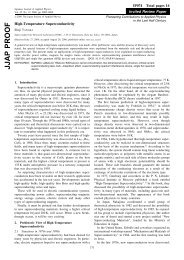
Data on sample No. 1 are shown <strong>in</strong> Fig. 1, and<br />
on sample No. 2 <strong>in</strong> Fig. 2. The diagonal l<strong>in</strong>e<br />
through the orig<strong>in</strong> represents the calibration.<br />
It is the signal correspond<strong>in</strong>g to zero flux <strong>in</strong> the<br />
cyl<strong>in</strong>der and hole <strong>in</strong> the presence of the applied<br />
field as described above. The experimental<br />
po<strong>in</strong>ts shown on the graph represent two types of<br />
data <strong>for</strong> each value of the applied field. The<br />
po<strong>in</strong>ts on the bottom half of each graph represent<br />
the signal <strong>in</strong> the presence of the applied field<br />
after cool<strong>in</strong>g through the transition <strong>in</strong> that field.<br />
The po<strong>in</strong>ts <strong>in</strong> the upper half represent the trapped<br />
flux after the field is subsequently reduced to<br />
zero. For each po<strong>in</strong>t <strong>in</strong> the lower curve there<br />
is a correspond<strong>in</strong>g po<strong>in</strong>t <strong>in</strong> the upper curve. The<br />
solid l<strong>in</strong>es represent calculated <strong>in</strong>tegral values<br />
of hc/2e.<br />
It can be seen that certa<strong>in</strong> features of the data<br />
are <strong>com</strong>mon to both samples. (1) Below a certa<strong>in</strong><br />
value of applied field, the total cross section<br />
of the cyl<strong>in</strong>der acts as a perfect diamagnet, exclud<strong>in</strong>g<br />
all the flux, and no flux is trapped when<br />
the applied field is turned off. (We believe this<br />
43
'<br />
VOLUME 7, NUMBER 2<br />
PHYSICAL REVIEW LETTERS Jvr.v 15, 1961<br />
4.0—<br />
5-0— 0 o o o<br />
0' 0<br />
0 60@ 0<br />
2.0—<br />
5 0<br />
l.o—<br />
-l.p<br />
—2.0<br />
-4.0<br />
-5.0<br />
o0<br />
0( MAO<br />
o<br />
8 g<br />
Q ~ + O $0~0<br />
000 tb<br />
8 o<br />
0.05 O.IO O.I5<br />
e&PPB $0<br />
0 aoocP ocP<br />
0 0<br />
0<br />
0.20<br />
tI;<br />
oo<br />
no<br />
0.25<br />
O<br />
OOO<br />
0<br />
0 0<br />
0 0<br />
o<br />
0 0<br />
0.50 0.55 0.40 0.45<br />
H- gauss<br />
FIG. 1. (Upper) Trapped flux<br />
<strong>in</strong> cyl<strong>in</strong>der No. 1 as a function<br />
of magnetic field <strong>in</strong> which the<br />
cyl<strong>in</strong>der was cooled below the<br />
superconduct<strong>in</strong>g transition. temperature.<br />
The open circles are<br />
<strong>in</strong>dividual data po<strong>in</strong>ts. The solid<br />
circles represent th, e average<br />
value of all data po<strong>in</strong>ts at a particular<br />
value of applied field <strong>in</strong>clud<strong>in</strong>g<br />
all the po<strong>in</strong>ts plotted<br />
and additional data which could<br />
not be plotted due to severe overlapp<strong>in</strong>g<br />
of po<strong>in</strong>ts. Approximately<br />
two hundred data po<strong>in</strong>ts are represented.<br />
The l<strong>in</strong>es are drawn<br />
at multiples of hc/2e. (Lower)<br />
Net flux <strong>in</strong> cyl<strong>in</strong>der No. 1 be<strong>for</strong>e<br />
turn<strong>in</strong>g off the applied field<br />
<strong>in</strong> which it was cooled as a function<br />
of the applied field. Open<br />
and solid circles have the same<br />
significance as above. The lower<br />
l<strong>in</strong>e is the diamagnetic calibration<br />
to which all runs have<br />
been normalized. The other l<strong>in</strong>es<br />
are translated vertically by successive<br />
steps of hc/2e.<br />
provides a way of obta<strong>in</strong><strong>in</strong>g a truly zero-magneticfield<br />
region. ) (2) When the applied field exceeds<br />
a certa<strong>in</strong> value, flux is trapped both with the field<br />
on, and after the applied field is turned off. The<br />
amount of this trapped flux with<strong>in</strong> the experimental<br />
accuracy of the data is hc/2e.<br />
The amount of trapped flux rema<strong>in</strong>s constant<br />
as the applied field is <strong>in</strong>creased until a value<br />
approximately three times that <strong>for</strong> the <strong>in</strong>itial<br />
trapp<strong>in</strong>g is reached, at which po<strong>in</strong>t the trapped<br />
flux <strong>in</strong>creases to about twice the orig<strong>in</strong>al amount.<br />
There appears to be evidence <strong>for</strong> additional<br />
changes at five and seven times the field <strong>for</strong> the<br />
first trapp<strong>in</strong>g.<br />
Fluctuations <strong>in</strong> the data are caused by variations<br />
<strong>in</strong> the zero of the magnetic field, changes<br />
<strong>in</strong> the ga<strong>in</strong>, vibration amplitude, drift, and random<br />
noise <strong>in</strong> the detection system. The approximately<br />
two hundred data po<strong>in</strong>ts <strong>for</strong> sample No. 1<br />
were taken over a three-week period dur<strong>in</strong>g<br />
which the drift and noise were gradually improved.<br />
The fluctuations of the data around the<br />
values 0 and hc/2e represent, we believe, expected<br />
scatter from drift and noise. This scatter<br />
has been greatly improved <strong>for</strong> sample No. 2.<br />
For both samples the data are consistent with<br />
values 0 and hc/2e <strong>for</strong> the trapped flux as described<br />
above.<br />
Near the transition to the second and third<br />
steps the fluctuations <strong>in</strong> the data are greater,<br />
and <strong>in</strong> addition po<strong>in</strong>ts lie between the steps.<br />
Some <strong>in</strong>creased scatter is expected s<strong>in</strong>ce the<br />
absolute fluctuations due to changes <strong>in</strong> ga<strong>in</strong> and<br />
vibration amplitude are proportional to the size<br />
of the signal. The po<strong>in</strong>ts between the steps do<br />
not necessarily <strong>in</strong>dicate trapp<strong>in</strong>g of non<strong>in</strong>tegral<br />
values of flux. S<strong>in</strong>ce the observed signal is the<br />
sum of the emf's from coils at the two ends of<br />
the sample, a flux l<strong>in</strong>e pass<strong>in</strong>g out of the cyl<strong>in</strong>der<br />
at some po<strong>in</strong>t other than the end may produce<br />
different signals <strong>in</strong> the two coils. The two<br />
ends of the cyl<strong>in</strong>der are not quite identical; so<br />
near the transition region it is probable that the<br />
two ends might trap a different number of units
VOLUME 7, NUMBER 2 P 8YSI CAL R K VI K%' LKTTKRS Jvx.v 15, 1961<br />
of flux, the extra unit be<strong>in</strong>g shoved out the side<br />
of the cyl<strong>in</strong>der. This is especially probable <strong>for</strong><br />
sample No. 1 s<strong>in</strong>ce the x-ray photograph showed<br />
a break <strong>in</strong> the t<strong>in</strong> coat<strong>in</strong>g near the middle of the<br />
cyl<strong>in</strong>der. Also, it is known that flux can create<br />
a normal region <strong>in</strong> a superconductor by shr<strong>in</strong>k<strong>in</strong>g<br />
<strong>in</strong> size until the critical field is exceeded.<br />
In this experiment we were unable to measure<br />
<strong>in</strong>dependently the signals from the two coils.<br />
However, <strong>in</strong> future experiments this will be done<br />
to remove this ambiguity. It is <strong>in</strong>terest<strong>in</strong>g to note<br />
that no <strong>in</strong>termediate po<strong>in</strong>ts are found outside the<br />
expected scatter of the data near the first step.<br />
One po<strong>in</strong>t <strong>for</strong> which no flux was trapped was<br />
found near the center of the first step with sample<br />
No. 1.<br />
In conclusion, we f<strong>in</strong>d:<br />
1. The flux trapped <strong>in</strong> a superconduct<strong>in</strong>g cyl<strong>in</strong>der<br />
both <strong>in</strong> the presence and absence of an applied<br />
magnetic field is not cont<strong>in</strong>uous but exhibits a<br />
step behavior, the first step occurr<strong>in</strong>g <strong>for</strong><br />
4 =bc/2e, with<strong>in</strong> experimental error <strong>in</strong> the data.<br />
Consider<strong>in</strong>g all sources of error, we estimate<br />
that the value of the trapped flux at the first<br />
step is hc/2e+ 20%. lf the correction to the<br />
size of the cyl<strong>in</strong>der due to the presence of the<br />
copper should prove <strong>in</strong>valid, an additional 11%<br />
error could arise <strong>for</strong> the large cyl<strong>in</strong>der and 17%<br />
<strong>for</strong> the small cyl<strong>in</strong>der.<br />
2. The data seem to <strong>in</strong>dicate additional steps<br />
at hc/e, Shc/2e, and 2hc/e. The po<strong>in</strong>ts appear<strong>in</strong>g<br />
between these levels will be <strong>in</strong>vestigated<br />
further.<br />
3. The ratio of the fields at which the steps<br />
occur are approximately 1, 3, 5, and 7. In the<br />
first cyl<strong>in</strong>der (<strong>for</strong> which the effective cross-sectional<br />
area of the cyl<strong>in</strong>der is 2.33 times the area<br />
of the hole), the first jump occurs when the flux<br />
pass<strong>in</strong>g through the total effective cross section<br />
of the cyl<strong>in</strong>der <strong>in</strong> the normal state is approximately<br />
hc/2e.<br />
For cyl<strong>in</strong>der No. 2 (<strong>in</strong> which the effective crosssectional<br />
area of the cyl<strong>in</strong>der is 1.1 times the<br />
area of the hole), the first jump occurs when the<br />
flux pass<strong>in</strong>g through the total effective cross section<br />
of the cyl<strong>in</strong>der <strong>in</strong> the normal state is approxi-<br />
2.0—<br />
0 0<br />
0<br />
0<br />
a<br />
FIG. 2. (Upper) Trapped flux<br />
<strong>in</strong> cyl<strong>in</strong>der No. 2 as a function<br />
of magnetic field <strong>in</strong> which the<br />
cyl<strong>in</strong>der was cooled below the<br />
superconduct<strong>in</strong>g transition temperature.<br />
The circles and triangles<br />
<strong>in</strong>dicate po<strong>in</strong>ts <strong>for</strong> oppositely<br />
directed applied fields.<br />
L<strong>in</strong>es are drawn at multiples of<br />
hc/2e. (Lower) Net flux <strong>in</strong> cyl<strong>in</strong>der<br />
No. 2 be<strong>for</strong>e turn<strong>in</strong>g off<br />
the applied field as a function<br />
of the applied field. The circles<br />
and triangles are po<strong>in</strong>ts <strong>for</strong> oppositely<br />
directed applied fields.<br />
The lower l<strong>in</strong>e is the diamagnetic<br />
calibration to which all runs have<br />
been normalized. The other<br />
l<strong>in</strong>es are translated vertically<br />
by successive steps of hc/2e.<br />
LO—<br />
I.O<br />
2.0<br />
5.0<br />
0 0.05<br />
I<br />
0.6<br />
0<br />
d<br />
-0 90 0<br />
I<br />
I<br />
CN5 0.4P<br />
H — gouss
VOLUME 7, NUMBER 2 PHYSICAL REVIEW LETTERS JULY 15, 1961<br />
mately 0.6hc/2e. In a follow<strong>in</strong>g Letter, Byers<br />
and Yange conclude that <strong>in</strong> a th<strong>in</strong> r<strong>in</strong>g the first<br />
jump should occur at 0.5hc/2e.<br />
4. S<strong>in</strong>ce the time constant of our measur<strong>in</strong>g<br />
circuit is 25 seconds, this experiment gives<br />
only a large upper limit <strong>for</strong> the time <strong>in</strong>volved<br />
<strong>in</strong> reach<strong>in</strong>g these quantized flux values. Mercereau<br />
and Vant-Hull~ have reported a negative<br />
experiment designed to observe quantized flux<br />
<strong>in</strong> a 1-mm r<strong>in</strong>g cooled 6000 times per second<br />
through the superconduct<strong>in</strong>g transition <strong>in</strong> a small<br />
magnetic field. It is possible that the difference<br />
<strong>in</strong> their results and the results of our experiment<br />
are due to a m<strong>in</strong>imum time necessary to establish<br />
equilibrium. We are plann<strong>in</strong>g to <strong>in</strong>vestigate<br />
this relaxation time.<br />
%'e have had the pleasure of discuss<strong>in</strong>g the<br />
results of this experiment with N. Byers, C. N.<br />
Yang, and L, Onsager, whose <strong>in</strong>terpretation of<br />
these results appear <strong>in</strong> the follow<strong>in</strong>g Letters.<br />
One of us (WMF) also wishes to acknowledge his<br />
<strong>in</strong>debtedness to F. London and M. J. Buck<strong>in</strong>gham<br />
who greatly <strong>in</strong>fluenced his concept of the superfluid<br />
state. We also wish to thank F. Bloch, L. L<br />
Schiff, and J. D. Bjorken <strong>for</strong> many stimulat<strong>in</strong>g<br />
discussions of the experiment. We wish to acknowledge<br />
the <strong>in</strong>valuable assistance of M. B.<br />
Goodw<strong>in</strong>.<br />
*Work supported <strong>in</strong> part by grants from the National<br />
Science Foundation, the Office of Ordnance Research<br />
(U. S. Army), and the L<strong>in</strong>de Company.<br />
~F. London, Superfluids (John Wiley @ Sons, New<br />
York, 1950), p. 152.<br />
2L. Onsager, Proceed<strong>in</strong>gs of the International Conference<br />
on Theoretical Physics, Kyoto and Tokyo,<br />
September, 1953 (Science Council of Japan, Tokyo,<br />
1954), pp. 935-6.<br />
3Such a possibility was mentioned by Lars Onsager<br />
to one of us (WMF) at the conference on superconductivity<br />
<strong>in</strong> Cambridge, England, 1959 (unpublished).<br />
S. Foner, Rev. Sci. Instr. 30, 548 (1959).<br />
E. Burton, H. Grayson-Smith, and J. Wilhelm,<br />
Phenomena at the Temperature of Liquid Helium<br />
(Re<strong>in</strong>hold Publish<strong>in</strong>g Corporation, New York, 1940),<br />
p. 120.<br />
~N. Byers and C. N. Yang, follow<strong>in</strong>g Letter [Phys.<br />
Rev. Letters 7, 46 (1961)].<br />
~J. E. Mercereau and L. L. Vant-Hull, Bull. Am.<br />
Phys. Soc. 6, 121 (1961}.<br />
L. Onsager, this issue [Phys. Rev. Letters 7, 50<br />
(1961)].<br />
THEORETICAL CONSIDERATIONS CONCERNING QUANTIZED MAGNETIC FLUX<br />
IN SUI'ERCONDUCTING CYLINDERS*<br />
N. Byers and C. N. Yang'<br />
Institute of Theoretical Physics, Department of Physics, Stan<strong>for</strong>d University, Stan<strong>for</strong>d, Cali<strong>for</strong>nia<br />
(Received June 16, 1961)<br />
In a recent experiment, the magnetic flux<br />
through a superconduct<strong>in</strong>g r<strong>in</strong>g has been found<br />
to be quantized <strong>in</strong> units of ch/2e. Quantization<br />
<strong>in</strong> twice this unit has been briefly discussed by<br />
London' and by Onsager. ' Onsager' has also<br />
considered the possibility of quantization <strong>in</strong><br />
units ch/2e due to pairs of electrons <strong>for</strong>m<strong>in</strong>g<br />
quasi-bosons.<br />
The previous discussions' leave unresolved<br />
the question whether quantization of the flux is<br />
a new physical pr<strong>in</strong>ciple or not. Furthermore,<br />
sometimes the discussions seem' to be based on<br />
the assumption that the wave function of the superconductor<br />
<strong>in</strong> the presence of the flux is proportional<br />
to that <strong>in</strong> its absence, an assumption<br />
which is not correct. We shall show <strong>in</strong> this Letter<br />
that (i) no new physical pr<strong>in</strong>ciple is <strong>in</strong>volved<br />
<strong>in</strong> the requirement of the quantization of magnetic<br />
flux through a superconduct<strong>in</strong>g r<strong>in</strong>g, (ii) the<br />
Meissner effect is closely related to the requirement<br />
that the flux through any area with a boundary<br />
ly<strong>in</strong>g entirely <strong>in</strong> superconductors is quantized,<br />
and (iii) the quantization of flux is an<br />
<strong>in</strong>dication of the pair<strong>in</strong>g of the electrons <strong>in</strong> the<br />
s uperconductor.<br />
Macroscopic discussion. Consider a, multiply<br />
connected superconduct<strong>in</strong>g body P with a tunnel<br />
0 (Fig. 1). We shall only discuss macroscopic<br />
FIG. 1. Multiply connected superconductor,