f g* g g' h f' f - bei Duepublico - Universität Duisburg-Essen
f g* g g' h f' f - bei Duepublico - Universität Duisburg-Essen
f g* g g' h f' f - bei Duepublico - Universität Duisburg-Essen

Create successful ePaper yourself
Turn your PDF publications into a flip-book with our unique Google optimized e-Paper software.
Reconfiguration of User Interface Models for<br />
Monitoring and Control of Human-Computer Systems<br />
Von der Fakultät für Ingenieurwissenschaften<br />
der <strong>Universität</strong> <strong>Duisburg</strong>-<strong>Essen</strong><br />
zur Erlangung des akademischen Grades eines<br />
Doktors der Ingenieurwissenschaften<br />
genehmigte Dissertation<br />
von<br />
Benjamin Weyers<br />
aus <strong>Essen</strong><br />
Referent: Univ.-Prof. Dr. rer. nat. Wolfram Luther, <strong>Universität</strong> <strong>Duisburg</strong>-<strong>Essen</strong><br />
Korreferent: Univ.-Prof. Dr.-Ing. Dirk Söffker, <strong>Universität</strong> <strong>Duisburg</strong>-<strong>Essen</strong><br />
Korreferent: Assoc. Prof. Dr. rer. nat. Nelson Baloian, Universidad de Chile<br />
Tag der mündlichen Prüfung: 19.12.2011
Für Ann-Kathrin
Danksagung<br />
Die vorliegende Ar<strong>bei</strong>t entstand während meiner Promotion als Stipendiat der Studienstiftung<br />
des deutschen Volkes am Lehrstuhl für Computergraphik und wissenschaftliches Rechnen an<br />
der <strong>Universität</strong> <strong>Duisburg</strong>-<strong>Essen</strong>.<br />
Mein aufrichtiger Dank gilt in erster Linie meinem Doktorvater Herrn Prof. Dr. Wolfram<br />
Luther, der diese Ar<strong>bei</strong>t angeregt und wissenschaftlich begleitet hat. Trotz vielerlei anderer<br />
Verpflichtungen hat er meine Ar<strong>bei</strong>t stets unterstützt und fand immer Zeit für Rat und Anregungen.<br />
Vor Allem bin ich ihm für seinen offenen Umgang und für die vielen fruchtbaren<br />
Diskussionen und Gespräche dankbar.<br />
Auch möchte ich mich an dieser Stelle <strong>bei</strong> meinen Korreferenten Herrn Prof. Dr. Nelson<br />
Baloian und Herrn Prof. Dr.-Ing. Dirk Söffker für die vielen Anregungen und wissenschaftlichen<br />
Kooperationen bedanken, die mich immer wieder aufs Neue motiviert und inspiriert haben.<br />
Die Ar<strong>bei</strong>tsatmosphäre am Lehrstuhl für Computergraphik und wissenschaftliches Rechnen<br />
werde ich immer in guter Erinnerung behalten. Ich danke daher allen Kollegen für das besonders<br />
gute und freundschaftliche Ar<strong>bei</strong>tsklima, sowie für die vielen fachlichen und nicht-fachlichen<br />
Gespräche. Insbesondere möchte ich Herrn Dr. Thomas Pilz und Herrn Dr. Roger Cuypers<br />
danken, die nicht nur Kollegen waren, sondern Freunde geworden sind. Auch möchte ich mich<br />
<strong>bei</strong> den zahlreichen Studenten bedanken, die ich im Rahmen ihrer Abschlussar<strong>bei</strong>ten betreuen<br />
durfte. Da<strong>bei</strong> möchte ich mich insbesondere <strong>bei</strong> Herrn Dipl.-Inform. Armin Strobl, Herrn Dipl.-<br />
Inform. Jan Stückrath, Frau Dipl.-Inform. Sema Kanat, Frau Dipl.-Inform. Dudu Canpolat,<br />
Herrn Dipl.-Inform. Cüneyt Altunok, Herrn Dipl.-Inform. Alexander Emeljanov, Frau Dipl.-<br />
Inform. Yu Liu, Herrn Dipl.-Inform. Nikolaj Borisov, Frau Hanna Berdys, B.Sc. und Herrn<br />
Patrick Berdys, B.Sc. bedanken.<br />
Ganz herzlich möchte ich mich <strong>bei</strong> meiner Familie und meinen Freunden für ihre Ermutigungen<br />
und den Halt bedanken, den sie mir immer wieder gegeben haben. Vor Allem möchte<br />
ich mich allerdings <strong>bei</strong> meinen Eltern, Annegret und Wolfgang, für ihre immer währende Unterstützung<br />
während meines Studiums und meiner Promotion bedanken, die im Wesentlichen<br />
zum Entstehen dieser Ar<strong>bei</strong>t <strong>bei</strong>getragen hat.<br />
Mein ganz besonderer Dank gebührt allerdings meiner Ehefrau Ann-Kathrin. Sie hat es nicht<br />
nur immer wieder geschafft mich in schweren Situationen aufzubauen, sondern war auch jederzeit<br />
für mich da. Sie hat mir in vielen Momenten den nötigen Rückhalt gegeben und stand<br />
stets hinter mir und meinen Entscheidungen. Sie fand immer die passenden Worte und öffnete<br />
mir den Blick für andere Sichtweisen. Ich danke Dir von ganzem Herzen.<br />
<strong>Duisburg</strong>, im Dezember 2011 Benjamin Weyers
Contents<br />
1. Introduction 1<br />
2. Human-Computer Interaction 7<br />
2.1. Introduction . . . . . . . . . . . . . . . . . . . . . . . . . . . . . . . . . . . . . . . 7<br />
2.2. Cognitive Psychology and Modeling . . . . . . . . . . . . . . . . . . . . . . . . . 10<br />
2.3. Human Error . . . . . . . . . . . . . . . . . . . . . . . . . . . . . . . . . . . . . . 13<br />
2.4. The Role of Automation . . . . . . . . . . . . . . . . . . . . . . . . . . . . . . . . 15<br />
2.5. Task and Dialog Modeling . . . . . . . . . . . . . . . . . . . . . . . . . . . . . . . 16<br />
2.6. Adaptive User Interfaces . . . . . . . . . . . . . . . . . . . . . . . . . . . . . . . . 18<br />
2.7. Reconfiguration . . . . . . . . . . . . . . . . . . . . . . . . . . . . . . . . . . . . . 20<br />
2.8. Multimodal and Multi-User Interfaces . . . . . . . . . . . . . . . . . . . . . . . . 21<br />
3. Formal Modeling of User Interfaces 25<br />
3.1. Nomenclature . . . . . . . . . . . . . . . . . . . . . . . . . . . . . . . . . . . . . . 25<br />
3.2. User Interface Modeling . . . . . . . . . . . . . . . . . . . . . . . . . . . . . . . . 33<br />
3.3. Formalization of Interaction Logic . . . . . . . . . . . . . . . . . . . . . . . . . . 35<br />
3.4. Transformation to Reference Nets . . . . . . . . . . . . . . . . . . . . . . . . . . . 46<br />
3.5. Extension of Interaction Logic Modeling . . . . . . . . . . . . . . . . . . . . . . . 87<br />
3.6. Formal Modeling of Physical Representation . . . . . . . . . . . . . . . . . . . . . 92<br />
3.7. Conclusion . . . . . . . . . . . . . . . . . . . . . . . . . . . . . . . . . . . . . . . 95<br />
4. Reconfiguration and Redesign 97<br />
4.1. Nomenclature . . . . . . . . . . . . . . . . . . . . . . . . . . . . . . . . . . . . . . 97<br />
4.2. Formal Reconfiguration . . . . . . . . . . . . . . . . . . . . . . . . . . . . . . . . 98<br />
4.3. Redesign . . . . . . . . . . . . . . . . . . . . . . . . . . . . . . . . . . . . . . . . . 126<br />
4.4. Conclusion . . . . . . . . . . . . . . . . . . . . . . . . . . . . . . . . . . . . . . . 127<br />
5. Modeling and Simulation of Formal User Interfaces 129<br />
5.1. Introduction . . . . . . . . . . . . . . . . . . . . . . . . . . . . . . . . . . . . . . . 129<br />
5.2. The UIEditor Framework . . . . . . . . . . . . . . . . . . . . . . . . . . . . . . . 131<br />
5.3. Future Extensions . . . . . . . . . . . . . . . . . . . . . . . . . . . . . . . . . . . 152<br />
5.4. Conclusion . . . . . . . . . . . . . . . . . . . . . . . . . . . . . . . . . . . . . . . 153<br />
6. User Interface Reconfiguration in Interactive Learning Systems 155<br />
6.1. Introduction . . . . . . . . . . . . . . . . . . . . . . . . . . . . . . . . . . . . . . . 155<br />
6.2. Computer-Supported Cooperative Learning . . . . . . . . . . . . . . . . . . . . . 156<br />
6.3. Simulation Environment for Cryptographic Algorithms . . . . . . . . . . . . . . . 160<br />
6.4. Evaluation Study and Results . . . . . . . . . . . . . . . . . . . . . . . . . . . . . 165<br />
6.5. Conclusion . . . . . . . . . . . . . . . . . . . . . . . . . . . . . . . . . . . . . . . 172<br />
iii
Contents<br />
7. Error Reduction through Reconfiguration of User Interfaces 173<br />
7.1. Introduction . . . . . . . . . . . . . . . . . . . . . . . . . . . . . . . . . . . . . . . 173<br />
7.2. Psychological Principles . . . . . . . . . . . . . . . . . . . . . . . . . . . . . . . . 174<br />
7.3. Input Reconfiguration of User Interfaces . . . . . . . . . . . . . . . . . . . . . . . 175<br />
7.4. Output Reconfiguration of User Interfaces . . . . . . . . . . . . . . . . . . . . . . 183<br />
7.5. Conclusion . . . . . . . . . . . . . . . . . . . . . . . . . . . . . . . . . . . . . . . 191<br />
8. Automatic Reconfiguration of User Interfaces 193<br />
8.1. Introduction . . . . . . . . . . . . . . . . . . . . . . . . . . . . . . . . . . . . . . . 193<br />
8.2. Reconfiguration System Architecture . . . . . . . . . . . . . . . . . . . . . . . . . 197<br />
8.3. Interaction Analysis . . . . . . . . . . . . . . . . . . . . . . . . . . . . . . . . . . 199<br />
8.4. Conclusion . . . . . . . . . . . . . . . . . . . . . . . . . . . . . . . . . . . . . . . 200<br />
9. Conclusion and Future Work 201<br />
A. The UIEditor Framework—File Formats 205<br />
B. The UIEditor Framework—Availability 213<br />
List of Figures 215<br />
List of Tables 219<br />
Bibliography 221<br />
iv
1. Introduction<br />
In recent decades, computer science has become increasingly established as the leading field in<br />
the development of technologies in interdisciplinary scientific projects. Various examples can<br />
be found in communication technology, mechanical engineering, medicine, economics and other<br />
disciplines. Having arisen from early data processing in the 1950s, today computer science concentrates<br />
on investigating abstract description languages often based on mathematical concepts<br />
and working towards computer-based implementations as tools for investigation or as final products.<br />
The resulting modeling approaches seek to offer a universal platform for various research<br />
disciplines, to the benefit of all participants. Thus, developing abstract modeling strategies for<br />
use in digital systems, computer science offers a common universal basis in interdisciplinary<br />
research projects for communication, modeling, and development, as well as tool support for<br />
scientific work.<br />
Motivation<br />
With the development of electric systems and highly integrated processing units, technical systems<br />
are becoming ever more complex, as are the control and monitoring tasks to be conducted<br />
by human users. For this reason, the development of human-computer interfaces has become<br />
the focus of research seeking to reduce the complexity of technical systems by implementing<br />
user interfaces that link psychological aspects, on the one hand, with technical requirements,<br />
on the other. This highly interdisciplinary research area is human-computer interaction. Its<br />
aim is to develop theories, concepts, and tools that offer user interfaces for successful control of<br />
complex technical systems to simplify everyday life.<br />
The field of human-computer interaction involves two scientific areas: psychology, which<br />
investigates humans, their behavior, and how they understand the world, and engineering,<br />
which develops and investigates complex technical systems. Computer science concerns itself<br />
primarily with modeling methods to describe and investigate systems in executable fashion.<br />
Thus, computer science supports (formal, mathematical) modeling methods that can be run on<br />
computers for simulation, investigation, validation, and verification paired with tool support<br />
for applied modeling by psychologists and/or engineers. In this context, computer science<br />
can support methods and tools for modeling systems from the perspective of psychology as<br />
well as engineering. Furthermore, computer sciences can use results from both scientific areas<br />
to enhance success in human-computer interaction and offer a formal basis for research on<br />
merging different worlds to create efficient and effective interactive human-computer systems.<br />
In this context, engineering offers various application scenarios, where psychology supports<br />
the creation of mental models, statistical evaluation approaches, and cognitive concepts like<br />
situation awareness, etc.<br />
This visionary view of future work in human-computer interaction motivates a modeling<br />
approach for user interfaces that is, on the one hand, suitable for visual and expert-based<br />
modeling and, on the other, formally defined to offer a solid basis for future integration of<br />
1
1. Introduction<br />
related psychological and engineering models as well as to make models directly executable on<br />
computers. In the end, this approach reduces the gap between modeling and implementation.<br />
Thus, this executable, computer-based communication platform enables the combination of<br />
concepts from psychology and engineering.<br />
Furthermore, both psychology and engineering are interested in building models that simplify<br />
the real world to the degree that it can be understood by researchers and becomes easier to<br />
investigate. Computer science offers a huge set of modeling languages and approaches based on<br />
various concepts and ideas, always with the goal of using computers to execute and investigate<br />
certain models. In this context, overlapping concerns are identified in building models of the<br />
human and/or the technical systems involved, which also argue for developing and implementing<br />
a solid computer-based and executable language for integrating models into user interface<br />
creation processes and implementations.<br />
Goals<br />
The goal of this dissertation is to develop a formal and visual modeling language to describe<br />
human-computer interaction embedded as an executable model of user interface design. This<br />
formal approach will be extended by formal transformation concepts to offer options for formal<br />
reconfiguration of user interfaces to make formally modeled user interfaces more flexible and<br />
adaptable. Thus, they can be reconfigured in accordance with psychological research integrating<br />
implicit psychological models to formal user interfaces. One example of this is reconfiguring a<br />
user interface to reflect the user’s mental model of a machine. On the other hand, results from<br />
engineering research can be easily introduced into formal user interface models and thus into<br />
the interaction of the human user with the machine. For instance, the interaction processes<br />
between humans and technical systems that target specific goals can be embedded in the interaction<br />
model of a user interface. Thus, this dissertation describes the development of a flexible<br />
approach to formal user interface modeling, execution, and reconfiguration. This flexibility will<br />
allow future research to extend the current work by applying such concepts as the easy introduction<br />
of user interface adaption into an existing user interface model. Such extensions can<br />
serve as a common platform integrating elements from both psychology and engineering.<br />
Various concepts can be mentioned in this context. First, task models, which are familiar<br />
from human-computer interaction research, play a central role in identifying and describing the<br />
tasks a user tries to solve with a given (technical) system. Next, process and dialog modeling<br />
approaches should also be integratable into the formalism to be developed. From the engineering<br />
perspectives of automation and system control, the formalism needs to be flexible enough to<br />
introduce structures into the user interface model for the automation of certain control and<br />
monitoring tasks; it also needs to be able to embed concepts from psychology for the modeling<br />
of cognitive architectures and human behavior. Here, it is desirable to develop formal approaches<br />
for modeling mental models or use concepts in which the user embeds his mental model in the<br />
formally modeled user interface through reconfiguration. Furthermore, it should be possible to<br />
introduce structures into the user interface model to identify and avoid errors in interaction.<br />
It must be possible to validate and verify the resulting user interface model on the basis of<br />
mathematical and algorithmic concepts, as well as to simulate and execute it for use in real<br />
life. In conclusion, the formalism to be developed has to offer a solid basis for modeling data<br />
processing between a human user and a technical system and to make the resulting user interface<br />
reconfigurable at the same time. Furthermore, it should offer formalization abilities for building<br />
2
hybrid models by introducing different formalization approaches to the interaction model of a<br />
formal user interface based on data-driven communication between these models. This makes<br />
the formalism more flexible for future extensions and will prepare it for easier integration of<br />
formal models from other disciplines.<br />
Resulting from these requirements, a set of working packages can be inferred such as follows:<br />
1. Design of an architecture that subdivides a user interface into conceptual parts such as<br />
its suitability for formal modeling of human-computer interaction. Here, it is important<br />
to distinguish the functional or behavioral part of a user interface from its outward<br />
appearance. Furthermore, the role of the system to be controlled should be specified.<br />
2. Development of a visual language for modeling user interfaces based on this architecture<br />
with a view to formal simulation, reconfiguration, and validation and to offering a broad<br />
basis for the inclusion of other modeling approaches and concepts, including the ability<br />
to build hybrid models. To this end, the visual modeling language should be sustained<br />
by a well-known and highly developed formalism that also supports formal semantics for<br />
the newly introduced formalism, as well as tools and a vital research community.<br />
3. Development of formal reconfiguration of user interfaces based on the developed formalism.<br />
The reconfiguration approach must also be fully formal to prevent problems arising from<br />
applying semi-formal transformation approaches to formal and verifiable user interface<br />
models. In this way, both aspects are fully formal: (a) the user interface and (b) its<br />
reconfiguration. This reconfiguration approach should enable the introduction of further<br />
modeling concepts directly into formal user interface models. For instance, one task<br />
will be to embed in the user interface model the user’s mental model (or parts of it,<br />
such as a task model) as a representation of the system to be controlled. The goal of<br />
doing so is to reduce errors in interaction. Furthermore, computer-driven reconfiguration<br />
should also be possible in order to offer automatic generation of reconfiguration rules<br />
and their application to the user interface for implementing adaptive user interfaces as<br />
a topic of future work. This goal is similar to another: the introduction of automation<br />
concepts to user interface models implementing interaction processes in the user interface<br />
model, as well as elements of user help and guidance. In brief, the formal reconfiguration<br />
approach should make the formal modeling language flexible enough to meet the above<br />
set of requirements concerning hybrid modeling and the transformation of user interfaces’<br />
behavior in general.<br />
4. Implementation of a framework offering tools and components for visual modeling, simulation,<br />
and reconfiguration of formal user interfaces, as well as offering well-defined software<br />
interfaces for further extensions. The visual modeling component should be implemented<br />
first and foremost for generating user interfaces on the basis of the formal approach briefly<br />
discussed above. The simulation should be able to run the modeled user interface by combining<br />
a simulator for the formal representation of the visual modeling language with an<br />
interface to the system implementation, which should be controlled through the user interface.<br />
Still, the system to be controlled is not part of the investigation and implementation<br />
conducted for this dissertation. As will be shown below, the system is initially treated only<br />
as a black box represented to the outside world by its system interface (a set of system<br />
values). The reconfiguration module of the framework should offer an implementation of<br />
formal transformation systems paired with the data structures necessary for describing<br />
3
1. Introduction<br />
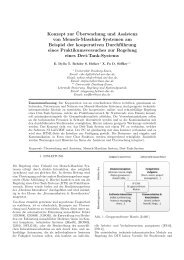
User Interface<br />
Modeling Architecture<br />
Extendable Software Framework<br />
for<br />
Modeling, Simulation, & Reconfiguration<br />
Formal User Interface<br />
Modeling<br />
Formal User Interface<br />
Reconfiguration<br />
Figure 1.1.: Working packages<br />
Evaluation<br />
transformations. It should also offer an interactive interface that implements a handy<br />
way for human users to apply certain reconfiguration operations to the user interface,<br />
such as integrating mental models into the user interface model in an interactive and iterative<br />
process. Furthermore, the framework should offer an open architecture for further<br />
extensions based on well-defined software interfaces; these might include the analysis of<br />
human-computer interaction, automatic generation of transformations and reconfigurations,<br />
formal verification tools, and data-driven analysis of interaction.<br />
5. Evaluation of the developed approach concerning its application in real work scenarios<br />
for identifying its use in various fields and its relevance for future research on integrating<br />
psychological models and models from engineering into human-computer interfaces. In<br />
the context of this work, the evaluation should determine the extent to which mental<br />
models can be integrated into formal user interface models and the extent to which this<br />
integration influences interaction and the number of errors made during interaction.<br />
Figure 1.1 shows the different working packages. Based on an architecture for modeling<br />
user interfaces, a formal modeling language should be developed along with a suitable formal<br />
approach to reconfiguration of user interfaces. These formalisms will be embedded in an expendable<br />
software framework for modeling, simulation, and reconfiguration, which will then be<br />
evaluated to determine the influence of the approach on human-computer interaction.<br />
Organization<br />
First, a short review of various research areas will be provided. It will identify areas and concepts<br />
in psychology and computer science relevant to the modeling of user interfaces and humancomputer<br />
interaction (Chapter 2). Thus, the survey of the relevant literature will embrace<br />
cognitive psychology as it relates to modeling, as well as the classification and identification<br />
of human error as relevant aspect in human-computer interaction for safety critical application<br />
scenarios. Aspects of automation and its influence on human-computer interaction will also be<br />
4
of interest. There are various approaches to task and dialog modeling for describing tasks to be<br />
fulfilled using a certain system, on the one hand, and, on the other, the extent to which dialogs<br />
between human and computer can be modeled and developed. Concerning the reconfiguration<br />
of user interfaces, various studies have been published and are included in the survey. A short<br />
preview of future work including an overview of work in the areas of multimodal and multi-user<br />
interfaces concludes Chapter 2.<br />
Based on this introduction to the field of human-computer interaction and its interdisciplinary<br />
environment, the developed formal approach to modeling user interfaces will be introduced. It<br />
is based on a visual language paired with formal transformation to reference nets, a special type<br />
of Petri nets (Chapter 3). The visual language integrates concepts of business process modeling.<br />
These processes will be subsumed in a container called interaction logic, which connects to<br />
physical elements of the user interface, called the physical representation, on the one hand, and<br />
with a well-defined interface of the system to be controlled, on the other. To avoid complex<br />
definitions of semantics, this modeling language will be equipped with a transformation algorithm<br />
that transforms it to reference nets offering formal syntax and semantics. Petri nets are a<br />
well-known family of formal languages for modeling non-deterministic processes also involving<br />
complex data types and continuous time concepts with an active and well-organized research<br />
community offering a broad formal background supporting the formalism and its use. Furthermore,<br />
reference nets will be shown as highly suitable for integrating different formalization to<br />
build the hybrid models necessary for integrating models from various scientific approaches.<br />
Nevertheless, Petri nets in general and reference nets in particular are formalisms that are<br />
equipped with a stable tool for modeling and simulation, which is further enhanced and developed<br />
[150].<br />
As a central element in platforms combining psychological concepts and technical systems,<br />
formal reconfiguration of user interfaces is of great importance. This approach offers transformation<br />
to various meta-models and third-party implementations without leaving the formal<br />
surroundings of the developed modeling language except for the use of hybrid modeling approaches<br />
(Chapter 4). This will be achieved through the introduction of formal graph transformation<br />
systems developed primarily in theoretical computer science and often used as a tool for<br />
defining semantics for graph-based languages. Here, graph transformation systems will be used<br />
to apply reconfiguration rules to the reference net-based model of a user interface in a formal<br />
manner, not least because of its solid theoretical foundation.<br />
Modeling approaches in computer science are only as helpful as the tools they support.<br />
Therefore, after introducing and defining formal modeling languages and their reconfiguration,<br />
the UIEditor framework will be described. This is a software framework implementing modules<br />
and software interfaces for visual modeling, simulation, and reconfiguration of user interfaces<br />
(Chapter 5). Various open source libraries were used for the visual modeling of graph-based<br />
structures. The simulation engine called Renew, which can be used for the modeling and<br />
simulation of reference nets, is included in the implementation and enables connection to thirdparty<br />
models during runtime by building executable hybrid interaction models. Furthermore,<br />
a graph transformation system has been implemented that uses XML-based file formats to<br />
describe transformation rules and reference nets based on the so-called double pushout approach.<br />
Chapters 6 and 7 introduce three studies showing that (a) it is possible to transform mental<br />
models into formally modeled user interfaces through reconfiguration and (b) reconfiguration<br />
reduces human error in interaction. The first of these concepts was investigated in the context<br />
of computer-supported cooperative learning. Here, it was possible to show that reconfiguration<br />
5
1. Introduction<br />
promotes success in the learning of cryptographic algorithms. Chapter 7 describes a study in<br />
which two processes had to be monitored and controlled by users who were able to reconfigure<br />
their user interfaces in accordance with their needs and their understanding of the processes.<br />
The control group was not able to use reconfiguration. In these studies, it was possible to show<br />
that reconfiguration of the user interface significantly influenced on the number of errors made<br />
by the individual user in handling malfunctions in the process.<br />
Chapter 8 offers a broader view of future work, identifying various areas for further development,<br />
introducing concepts of interaction analysis. The dissertation concludes with Chapter 9,<br />
which looks beyond interaction analysis and automatic reconfiguration to broader implications<br />
for future research.<br />
6
2. Human-Computer Interaction<br />
Human-computer interaction (HCI) is a well-known research field in computer science arising in<br />
the 1960s [177]. The study of HCI provides the background for this dissertation, which focuses<br />
primarily on the conception of terms and on positioning of this work in a wider context of<br />
HCI research. The motivation for this work can be shown by describing related literature and<br />
highlighting relevant historical aspects of and developments in HCI. Furthermore, the role of<br />
cognitive psychology in context of HCI and of this work will be explored.<br />
2.1. Introduction<br />
Beginning in the 1980s, interest in the area of HCI research increased dramatically with the<br />
advent of graphical user interfaces on the first personal computers like Apple’s Lisa and Macintosh,<br />
and IBM’s PC [231]. In HCI research, the focus of interest changes over time [247, 254].<br />
Up till now, the main interest has been to find the answer to the question how to build or<br />
create a dialog between human and computer such that the user can solve a task effectively and<br />
efficiently without making too many mistakes. For instance, in the early 1980s Shneiderman<br />
(1982) coined the term direct manipulation in his article “The future of interactive systems and<br />
the emergence of direct manipulation” [253] to describe a concept for HCI that still endures<br />
today. There, he characterizes the concept of direct manipulation as the “. . . visibility of the object<br />
of interest, rapid reversible actions and replacement of complex command language syntax<br />
by direct manipulation of the object of interest” [253, p. 246]. Three years later, Norman and<br />
his colleagues investigated this concept of direct manipulation from the perspective of cognitive<br />
science in their article “Direct manipulation interfaces” [117], identifying the pros and cons of<br />
HCI from this perspective. On the basis of these examples, it is clear that HCI research always<br />
combines various research areas. This is underscored by the various definitions of the term HCI<br />
and the differing areas of research it includes.<br />
The following definitions of the term HCI provide a more detailed view of this research area<br />
from the point of view of various authors, beginning with Dix, Finlay, Abowd, and Bealy who<br />
describe HCI as follows:<br />
As computer use became more widespread, an increasing number of researchers<br />
specialized in studying the interaction between people and computers, concerning<br />
themselves with the physical, psychological and theoretical aspects of this process.<br />
This research originally went under the name man-machine interaction, but this became<br />
HCI in recognition of the particular interest in computers and the composition<br />
of the user population! [64, p. 3]<br />
Dix et al. [64] identify three central aspects of HCI: (a) the physical aspect of interaction<br />
of user and computer, (b) the psychological aspect, which concentrates on the user, and (c)<br />
the theoretical background, on which the whole interaction process is based. This definition<br />
somehow lacks specificity. The last point in particular should be more clearly defined. Faulkner<br />
7
2. Human-Computer Interaction<br />
[88] also divides HCI research into three different areas, but gives clearer insight into its basic<br />
concepts and tools by characterizing the aim of HCI research:<br />
The aim [of HCI] is to create computer applications that will make users more efficient<br />
than they would be if they performed their tasks with an equivalent manual<br />
system. The last point is very important, since all too often computerized applications<br />
are produced that do not make the user’s task easier and more satisfying, nor<br />
do they save time. [88, p. 2]<br />
According to Faulkner, the aim of HCI research is the development of models, methods and<br />
concepts for generating user interfaces that make systems more usable in that they are more<br />
efficient and make fewer errors in solving given tasks. Faulkner goes on to sketch a way for HCI<br />
research to reach this goal by combining results from various areas of research:<br />
... [HCI] needs to gain its inputs from many other associated areas of study because<br />
it has to understand ... the computer system, the human user and the task the user<br />
is performing. [88, p. 3]<br />
Here, Faulkner characterizes three areas of investigation: (a) the computer systems, (b) the<br />
human user and (c) the task to be completed by the system to be accessed via the user interface<br />
under construction. This characterization differs from that given by Dix et al. It is more precise<br />
in the sense that it breaks down the whole research area of HCI to three subjects of investigation.<br />
Preece goes a step further in her perspective of HCI research. She also takes into account<br />
the environment as a necessary subject of HCI research, ending up with four major areas of<br />
investigation:<br />
The knowledge necessary for this [HCI study] comes from understanding how users<br />
interact with computer systems in particular work environments. This interaction<br />
consists of four components:<br />
• the user<br />
• who has to do a particular task or job<br />
• in a particular context<br />
• using a computer system. [219, p. 12]<br />
Preece tries to combine these four aspects in one term to describe the successful creation of<br />
a user interface: Usability. Preece characterizes a usable user interface (in other words a user<br />
interface with high usability) as a user interface that fulfills the following four requirements:<br />
8<br />
The goals of HCI are to develop and improve systems that include computers so<br />
that users can carry out their tasks:<br />
• safely (especially in critical systems like air traffic control)<br />
• effectively<br />
• efficiently, and<br />
• enjoyably.<br />
These aspects are collectively known as usability. [219, p. 14]
2.1. Introduction<br />
Preece defines usable user interfaces as safe based on their use in critical situations. This<br />
kind of situation can be characterized by such factors as a high level of stress and a short time<br />
period for decision-making in situations where many disturbing stimuli from the environment<br />
distract the user. Here, different interfaces are subject to different requirements if they are to<br />
meet Preece’s requirement of safeness. Thus, in the context of safeness, usability has to be<br />
determined depending on the type of user interface, the situation, and the user. From the point<br />
of view of haptic interfaces, like a control stick in an airplane cockpit, different requirements<br />
arise concerning usability than with a visual interface as in cases of process controlling, for<br />
instance, in a steel factory.<br />
Furthermore, interaction should be effective and efficient in the context of the task to be<br />
solved using the user interface. Here, effective means that a given task can be fulfilled using<br />
a given user interface, where efficiency in this context means that the interface should enable<br />
the task to be completed quickly and with as few errors and problems as possible. The last<br />
point, enjoyableness, seeks to convey a kind of ‘fun factor’ provided by using the interface.<br />
Here, Preece subsumes factors required for the user’s motivation to use the user interface. For<br />
instance, two user interfaces that are identically safe, effective, and efficient but differ in their<br />
‘fun factor’ affect their perceived usability only because the user’s motivation differs.<br />
In the book Designing the user interface [254], Shneiderman and Plaisant characterize HCI<br />
in a more complex way. They describe the criteria for the quality of a user interface concerning<br />
the aspects of “usability, universality, and usefulness” [254, p. 31] in context of the ISO norm<br />
9241 1 [254, p. 32] as a set of requirements:<br />
1. Time to learn. How long does it take for typical members of the user community<br />
to learn to use the actions relevant to a set of tasks?<br />
2. Speed of performance. How long does it take to carry out the benchmark tasks?<br />
3. Rate of errors by users. How many and what kind of errors do people make in<br />
carrying out the benchmark tasks? Although time to make and correct errors<br />
might be incorporated into the speed of performance, error handling is such a<br />
critical component of interface usage that it deserves extensive study.<br />
4. Retention over time. How well do users maintain their knowledge after an<br />
hour, a day, or a week? Retention may be linked closely to time to learn, and<br />
frequency of use plays an important role.<br />
5. Subjective satisfaction. How much did users like using various aspects of the<br />
interface? The answers can be ascertained by interviews or by written surveys<br />
that include satisfaction scales and space for free-form comments.<br />
The way in which Schneiderman and Plaisant outline the basic requirements of user interface<br />
development also defines a framework for testing the quality of a given user interface. By<br />
applying a set of benchmark tasks, the developer of a user interface can determine the quality<br />
of a given user interface design. Again, the human user is the focus, which seems to be a central<br />
theme in HCI research.<br />
It can be concluded from the work of the above authors, as well as that of Sears and Jacko<br />
[247]; Sharp, Rogers and Preece [252]; Rosson and Carroll [238]; and Card, Moran, and Newell<br />
[40], that HCI research embraces psychology, technology and sociology. At the same time, of<br />
1 http://www.iso.org/iso/iso catalogue/catalogue tc/catalogue detail.htm?csnumber=38009<br />
9
2. Human-Computer Interaction<br />
course, it includes computer science, which can be seen in the work of Palanque and Paternó<br />
[204], who describe the use of formal methods in HCI.<br />
In order to go into more detail, it is of interest to narrow the investigation to only central<br />
aspects. The goal is to create methods and tools to (a) model the user interface on various<br />
formal levels, (b) describe reconfiguration techniques based on this formalization and (c) to<br />
define ways of formalizing the results of differing types of HCI research, so that bridges can be<br />
built between formal studies in computer science and semi-formal or informal concepts from<br />
HCI and cognitive psychology research. The following sections will specify earlier work that<br />
contributes to the realization of these goals.<br />
2.2. Cognitive Psychology and Modeling<br />
Various methods for modeling the user, the user interface, the task and the interaction itself<br />
have been developed and investigated in HCI research. Concepts like hierarchical task trees,<br />
cognitive models and architectures are only a few examples of results from cognitive and HCI<br />
research. This section will make the user the focus of investigation in order to identify possible<br />
cognitive psychology approaches for further investigation and to build a basis for describing the<br />
connection between formal modeling and cognition. Before going further into detail, the term<br />
cognition should be briefly defined.<br />
In psychology, cognition is usually defined as a process of the mind. Thus, cognition describes<br />
the how humans think about, remember, perceive and learn information. Lachman, Lachman<br />
and Butterfield [154] introduced an analogy to computers to describe what cognitive psychology<br />
is about:<br />
Computers take a symbolic input, recode it, make decisions about the recoded input,<br />
make new expressions from it, store some or all of the input, and give back a<br />
symbolic output. By analogy that is what most cognitive psychology is about. It is<br />
about how people take in information, how they recode and remember it, how they<br />
make decisions, how they transform their internal knowledge states, and how they<br />
translate states into behavioral outputs. [154, p. 99]<br />
Parkin [207] cautions that “one must be careful about how far this analogy can be taken” [207,<br />
p. 12]. Nonetheless, he states that this analogy is still good enough to sketch out what cognitive<br />
psychology is about. For instance, he agrees that the central processing unit of a computer,<br />
which combines numbers using specific operations to obtain a result, can be compared to the<br />
identical part of the human mind doing the same thing. The same is true for information storage<br />
on hard drives for long-term purposes or RAM as an information buffer. The same modules can<br />
be found in the human mind as parts of information processing. But, says Parkin, the analogy<br />
ends at the point of information representation. The computer represents all information using<br />
a binary system, which is not true for the human mind.<br />
In order to understand the role of cognitive psychology in the context of this work, it is useful<br />
at this point to revisit the main goal of this work: the formal modeling of human-computer<br />
interfaces using a psychological approach to model human cognition. The basic idea is motivated<br />
by research results from the investigation of adaptive user interfaces, which will be examined<br />
in an upcoming section. Adaptive user interfaces seek to enhance the usability, efficiency and<br />
effectiveness of user interfaces by adapting them to users’ abilities and approaches to solving<br />
10
Human<br />
Cognition<br />
Matching &<br />
Decision Making<br />
Action<br />
Execution<br />
Mental<br />
Model<br />
User Interface<br />
System<br />
2.2. Cognitive Psychology and Modeling<br />
Task Model &<br />
Solving Strategy<br />
System Model<br />
Knowledge &<br />
Experience<br />
+<br />
Perception &<br />
Interpretation<br />
Task & Goal<br />
Figure 2.1.: Model of the human cognition for task solving—a brief overview<br />
a given task. In other words, adaptive user interfaces seek to adapt to the cognitive workflow<br />
of users who are solving a given task by using a certain tool. Figure 2.1 shows a model of<br />
human cognition, providing a deeper understanding of what is meant by the cognitive workflow<br />
of information processing and task solving.<br />
Nevertheless, this overview addresses only a few aspects of research into human cognition,<br />
focusing on the concept of mental models, but relating the computer analogy quoted above<br />
to human cognition in specific ways intended to support the formalization introduced in the<br />
following chapters.<br />
The concept of mental models seems to be a good point of connection between cognitive<br />
psychology and research into adaptive user interfaces. Thus, the structure and occurrence of<br />
mental models, which represent the tools and knowledge an individual uses to solve a given<br />
task, are highly relevant to the process of adapting user interfaces. A mental model represents<br />
the task and the strategy for solving the task using a computer or a machine as tool. The<br />
cognitive representation of the function of this tool is a further part of a mental model. An<br />
introductory overview of the term mental model and related research in the context of HCI is<br />
given by Rasmussen [227] and in the context of human factors by Wilson and Rutherford [298].<br />
Various psychological works introduced various views, approaches and concepts due to mental<br />
models. The definition given by Rouse and Morris [239] deals with the context of HCI:<br />
...[A mental model is a] mechanism whereby humans are able to generate descriptions<br />
of system purpose and form, explanations of system functioning and observed system<br />
states, and prediction of future system states. [239]<br />
In this sense, a mental model is essential for human cognition to interact with a machine.<br />
Thus, a mental model describes how to interpret and how to ‘understand’ the machine or its<br />
11
2. Human-Computer Interaction<br />
representation in the user interface such that a human can understand the state of the machine,<br />
know how it actually works and, in the end, predict future system behavior based on this knowledge.<br />
Additionally, the user should be able to affect the state of the machine in order to achieve<br />
any new state that might be necessary to perform given tasks.<br />
A mental model can also be seen as a massive repository of long-term memory as described by<br />
Carroll and Olson [41] and by Kluwe and Haider [136]. Parkin [207], Anderson [5] and Eysenck<br />
[87] offer more detailed information concerning models for organization of human memory as<br />
part of human cognition. In general, the term long-term memory can be described as a type<br />
of memory that offers learned concepts and experience as the basis for processes like decision<br />
making or interpretation in human cognition. Tulving [269] described long-term memory by<br />
dividing it into two parts: (a) episodic memory, which stores discrete personal events, for<br />
instance, what we had for dinner, and (b) semantic memory, which holds knowledge concerning<br />
language and the world, for instance, the fact that rain is wet. Furthermore, he [270] adds to<br />
this list procedural memory, which holds knowledge about how to do things, for instance, motor<br />
skills, like moving one’s legs and arms or grasping an object.<br />
As stated before, the mental model is one part of the whole cognitive process. Problems in this<br />
process can occur if a mental model is erroneous. An erroneous mental model can be described<br />
as an incorrect image of the reality. Errors will occur in user interaction with a machine that<br />
is based on an incorrect model. In conclusion, if errors occur, an erroneous mental model may<br />
be the reason. Mental models are generally constructed by practicing and training, and in this<br />
process, incorrect assumptions to the model can be manifested, as described by Kluwe [136].<br />
A further problem arises if the user interface with which the human user is interacting is<br />
not completely applicable to his mental model. For example, the user expects a value to be<br />
changed over time (part of the mental model) but its representation is only a static number<br />
not visualizing its changing characteristic. The user’s mental model of the machine might be<br />
correct, but if the user interface does not represent it in a specific and expected way, the user<br />
will have trouble matching the perceived information to his mental model and will start to<br />
generate wrong predictions concerning the current and future system state, which will result in<br />
errors in interaction and in controlling the machine. Here, an adaptive user interface will try<br />
to customize the presentation of the machine implemented in the user interface to the specific<br />
user’s mental model.<br />
Mental models are often described as sets of cues that in turn describe well-defined parts<br />
of a bigger work flow or process, such as described by Ericsson and Kintsch [85]. Thus, in<br />
this work the behavior of a user interface—also called interaction logic—is modeled as a set of<br />
interaction processes that can be directly matched to the cues in the user’s mental model. This<br />
is a first attempt to bridge the gap between formal modeling in user interface development and<br />
the research on mental models through the use of formal methods.<br />
A further way to describe mental models was introduced by Rauterberg, Schluep, and Fjeld<br />
[228]. They describe the use of Petri nets to represent mental models in the context of automatic<br />
determination of mental models from log files. They distinguish four types of models with<br />
differing complexity, where each can differentiated between five different levels in a mental<br />
model and include the system and the feedback from the system as mental representation.<br />
They developed this method of representing mental models when studying actual interaction of<br />
experts with a system to solve a given task, thus determining the cognitive complexity of using<br />
the system and interface. This approach to determining cognitive models of human users seems<br />
a promising way to provide formal modeling and validation for user interfaces.<br />
12
2.3. Human Error<br />
Another approach to formal description of cognitive models based on Petri nets was introduced<br />
by Werther [281]. He uses colored Petri nets to model the cognitive memory system<br />
as resource system defining the boundedness of human information processing. He extends<br />
the single modeling aspect by applying formal verification methods of Petri nets to models of<br />
human cognition. This ends up in statements concerning errors in such models, as well as<br />
assessments on occurring problems in interaction. A holistic approach based on the cognitive<br />
architecture introduced by Rasmussen [226] has been described in various works of Gamrad<br />
and Söffker [95, 96, 256]. Here, a concept called Situation-Operator-Modeling approach (SOM)<br />
describes the whole concept of knowledge and information processing of human cognition, which<br />
is transfered to colored Petri nets for verification and machine-based learning. This concept<br />
has been successfully used in various application scenarios like drive assistance [93] and arrival<br />
management in air traffic control [192].<br />
2.3. Human Error<br />
Preventing human error during interaction with a machine is one main motivation for interdisciplinary<br />
research in psychology and HCI. To reduce errors in interaction, the structure and<br />
mechanisms of human errors have to be understood before starting to create systems that will<br />
prevent them. To this end, many researchers have investigated the occurrence of and reasons<br />
for human errors in interaction with machines or other (more general) systems. The following<br />
overview of research into human error, while by no means complete, gives a brief introduction<br />
to the main aspects and concepts in this field of cognitive psychology.<br />
Endsley [83] introduces the framework modeling situation awareness that can be seen as<br />
a specified model based on the one shown in Figure 2.1. Situation awareness describes the<br />
distribution of a person’s attention in a certain situation at a given point in time, as well as<br />
his or her understanding of the current activities and expectations as to how the situation<br />
will progress. This definition of the term situation awareness is Endsley’s attempt to integrate<br />
various cognitive activities in handling complex and dynamic situations, starting with sensebased<br />
perception (visual or haptic perception, etc.) and including processes for decision making<br />
and problem solving [135]. Endsley defines three processes that establish situation awareness<br />
shown in Figure 2.2: “... the (1) perception (noticing) of the elements in the environment within<br />
a volume of time and space, the (2) comprehension of their meaning, and the (3) projection of<br />
their status in the near future” [84, p. 15].<br />
In Endsley’s framework modeling situation awareness, a classification of human errors can be<br />
specified due to [82] and [84]. In these publications, Endsley differentiates three levels of error<br />
in the context of the framework for situation awareness: errors in perception of the situation<br />
(level 1), errors in interpretation and understanding of the situation (level 2) and errors in the<br />
projection of future states (level 3).<br />
Other works, like that of Hollnagel [113], describe other approaches to the topic of human<br />
error. Hollnagel introduces a framework called the Cognitive Reliability and Error Analysis<br />
Method (CREAM). CREAM is another more specific approach than that shown in Figure 2.1<br />
to performance and error prediction, for instance, in controlling a nuclear power plant [114]. It<br />
classifies errors by separating them into genotypes and phenotypes. The genotype describes the<br />
possible cause of an erroneous action, whereas the phenotype describes a concrete occurrence<br />
of an erroneous action.<br />
Concerning errors in complex decision making, Wickens and Hollands [292], as well as Dörner<br />
13
2. Human-Computer Interaction<br />
Task/System Factors<br />
State of the<br />
Environment<br />
Individual Factors<br />
Perception<br />
of Elements<br />
in Current<br />
Situation<br />
Level 1<br />
SITUATION AWARENESS<br />
Comprehension<br />
of Current<br />
Situation<br />
Level 2<br />
● Goals and Objectives<br />
● Preconceptions<br />
(Expectations)<br />
Projection<br />
of Future<br />
Status<br />
Level 3<br />
● System Capability<br />
● Interface Design<br />
● Stress and Workload<br />
● Complexity<br />
● Automation<br />
Decision<br />
Information Processing<br />
Mechanisms<br />
Long Term<br />
Memory<br />
Automaticity<br />
Figure 2.2.: Framework of Situation Awareness (Endsley [83])<br />
Performance<br />
of<br />
Actions<br />
● Abilities<br />
● Experience<br />
● Training<br />
[67] describe the problem of saliency bias (Dörner’s Lautstärkeprinzip [67]). This saliency bias<br />
describes the problem of stimuli that direct a person’s attention to salient values that are less<br />
important than they appear. Especially in situations where the person is pressed for time, this<br />
bias can have a great influence on the occurrence of human error.<br />
These are only a few basic approaches to the classification of errors and investigation of<br />
the cognitive reasons occurring in the context of the cognitive information processing model<br />
presented in Figure 2.1. In the 1980s, authors such as Rasmussen [225] and Nowak and Carr<br />
[189] sought to identify general classification concepts for human error. More recent authors<br />
have examined the topic in more specific contexts, such as medical care [66, 140] and aviation<br />
[56, 251].<br />
Many recent studies have examined human error in aviation. An ergonomic perspective,<br />
for instance, was described by Edwards [69], who introduced the SHEL model differentiating<br />
between four components: S stands for the non-material part of the system to be controlled,<br />
also called software; H represents the hardware of that system, also involving the user interface<br />
hardware; E stands for the environment in which the further three elements are embedded in<br />
a coincidentally related manner; finally, L stands for liveware and represents the human user<br />
of the system. The relations between these components provide the significant information in<br />
the model. For instance, changing the hardware can also influence the interaction between<br />
user and system in a positive or negative way. This type of model has been used by accident<br />
investigators to identify human error in such situations (cf. [293, p. 29]). Other perspectives<br />
(e.g., behavioral, aeromedical, psychosocial, or organizational) and further reading on human<br />
error in aviation can be found in the work of Wiegmann and Shappell [293].<br />
Independent of how human error is defined or how the models and frameworks surrounding<br />
this topic are constructed, most approaches lack a foundation in formal HCI research. This<br />
14
2.4. The Role of Automation<br />
work will demonstrate the great value of incorporating human error research into the creation,<br />
adaption and reconfiguration of user interfaces in Chapter 7. By providing formal platforms on<br />
both sides, computer science research into adaptive user interfaces coupled with research into<br />
human error greatly benefits due to the understanding of how human and computer interact<br />
and thus significantly improves that interaction.<br />
2.4. The Role of Automation<br />
In the reconfiguration of user interfaces (cp. Chapter 4.2), automation plays a central role as an<br />
extension of the adaption of user interfaces. Here, automation refers to specific parts of technical<br />
systems that automate certain parts of controlling and monitoring of a system, for instance,<br />
an autopilot. According to Kluwe [135], automation has a great impact on human-computer or<br />
human-machine systems. This impact has been investigated mainly by Parasuraman and his<br />
colleagues [205, 206]. As they have shown, the role of automation can be seen in the four main<br />
functions of HCI and information processing like that given in Figure 2.1:<br />
Information retrieval How information about the system’s state, performance, and<br />
achievement of goals is acquired (‘Perception & Interpretation’ in Figure 2.1).<br />
Information analysis How data is integrated, and how information is evaluated and<br />
used for decision making (‘Plus’ box in Figure 2.1).<br />
Decision and selection of actions Recommendation and selection of actions based on<br />
system selection and operator information (‘Matching & Decision Making’ in Figure 2.1).<br />
Execution of actions by the operator and the system (‘Action’ and ‘Execution’ in Figure<br />
2.1).<br />
Automation can be applied to any of these functions depending on the level of control needed<br />
(high vs. low risk situations) and the character of the function itself. This kind of automation<br />
would be implemented in the ‘User Interface and System’ box in Figure 2.1. Parasuraman,<br />
Sheridan and Wickens [206] describe the role of automation and its functions in the context of<br />
air traffic control introduced above. High automation can be applied for information retrieval;<br />
in contrast, low automation should be applied for decision making and selection of actions in<br />
high risk situations in order to increase the operator’s freedom of action.<br />
There are further problems associated with automation. Wickens [291] identified three major<br />
problems:<br />
1. UNDERTRUST: Malfunctions, for instance unwarranted alarms, lead to a lost of trust<br />
in the automation of the controlled system. This undertrust can lead to erroneous intervention<br />
by the operator into automated parts of the system.<br />
2. OVERTRUST: Too high a degree of trust (overtrust) in automation can lead to such<br />
problems as a failure on the part of the operator to identify system malfunctions.<br />
3. OOTLUF: The acronym OOTLUF describes a problem arising from automatically generated<br />
alternatives to actions applied to the system. It has been shown that action sequences<br />
generated by the operator can be better remembered than automatically generated sequences.<br />
In the case of processes that were previously automated, the operator needs<br />
15
2. Human-Computer Interaction<br />
more time to generate the correct decisions and apply them to the system. This situation<br />
can also be described as a reentering of the operator into the control loop. Therefore,<br />
OOTLUF stands for “out of the loop unfamiliarity”.<br />
In the context of automation in aviation, a further term should be mentioned: automation<br />
surprises. This term refers to bad outcomes resulting from poorly implemented automation.<br />
Sarter, Woods, and Billings [240, 241, 299] describe problems posed by automation for aviation<br />
purposes and the potential for bad outcomes in high risk situations from an engineering<br />
perspective.<br />
Similarly, automation resulting from adaption or from the reconfiguration of user interfaces<br />
also has to be considered in the context of automation as introduced above. Problems arising<br />
from the reconfiguration of parts of the user interface need to be identified in an early stage<br />
or avoided altogether by applying findings like those described by Parasuraman. Thus, an<br />
environment that embeds the interaction logic of a user interface with formal reconfiguration<br />
or adaption offers a handy formal approach to the problem of automation.<br />
2.5. Task and Dialog Modeling<br />
The last box in Figure 2.1 has not yet been discussed in further detail. This is the ‘Task Model<br />
& Solving Strategy’ box. Closely related to the psychological approaches in HCI research introduced<br />
above are the formal and semi-formal modeling approaches to dialog and task modeling<br />
familiar from classical HCI research. The main motivation here is the modeling of a single, more<br />
a general ‘standard’ user in the context of solving tasks on the basis of hierarchical structures.<br />
The outcome of this modeling strategy is a user interface that is customized to the user’s needs<br />
concerning the strategy for solving given tasks and thereby increasing the effectiveness of using<br />
the user interface. Various models and approaches were developed in the past on different levels<br />
of task-planning strategies. Dix, Finlay, Abowd, and Beale [64] separate these levels into the<br />
following three layers:<br />
1. hierarchical representation of the user’s task and goal structure,<br />
2. linguistic and grammatical models, and<br />
3. physical and device-level models.<br />
Two well-known examples of hierarchical task models based on mental processing are GOMS<br />
and CCT. GOMS, developed by Card, Moran and Newell [38], is a modeling method based on<br />
four different concepts: (G)oals refers to the goals the user tries to achieve using an interactive<br />
system where those goals simultaneously represent points in the user’s memory; (O)perators<br />
refers to the elementary actions the user can or has to perform on the system, for instance,<br />
pressing a certain key; (M)ethods are rules governing how goals can be split into subgoals;<br />
(S)elections are rules for selecting a certain method, depending on the user and the context, for<br />
instance, the current state of the system.<br />
The second approach for using basic psychological research in mental processing and task<br />
solving is the (C)ognitive (C)omplexity (T)heory (CCT) introduced by Kieras and Polson [134].<br />
CCT ‘inherits’ GOMS’ goal decomposition concept and enriches it by introducing a system<br />
model to enlarge the power of prediction. In contrast to GOMS, CCT builds on production<br />
16
2.5. Task and Dialog Modeling<br />
rules defining a GOMS-like structure of task decomposition. Production rules in CCT are based<br />
on if-clauses offering else-branches.<br />
Based on the idea of using production systems, linguistic and grammatical models are further<br />
examples of task hierarchy models. The task action grammar developed by Payne and Green<br />
[214] is one well-known example of a linguistic approach.<br />
The (K)eystroke (L)evel (M)odel, KLM, is a physical or a device-level model and can be<br />
described as a simplified and practical instance of the GOMS family [184]. KLM was developed<br />
by Card, Moran and Newell [39] and describes elementary operations that are paired with an<br />
execution time. The execution sequence of these elementary operations that results from a task<br />
model, for instance, one using GOMS, can be used to predict (time) costs in interaction.<br />
All these early approaches were the first to combine psychological research into human cognition<br />
with computer science research into HCI. In their book The Psychology of Human-<br />
Computer Interaction, Card, Moran and Newell [40] brought the two worlds together as one<br />
part of computer science. Many other groups also worked on involving psychological concepts<br />
in the modeling of human-computer interfaces, including Anderson et al. [6], Robertson and<br />
Black [236], Norman [188], and Young [302].<br />
Besides task modeling and analysis, dialog modeling methods play an important role in HCI<br />
research. Here, a dialog refers to the exchange of information between human and computer<br />
in contrast to task-modeling techniques, which refer to decomposition and problem-solving<br />
strategies. This type of model is a departure from the context of cognitively motivated models<br />
such as GOMS and CCT. Dialog models in the sense presented in this section are not directly<br />
based on cognitive processes but are inspired by them.<br />
The first approach to modeling dialogs between human and computer was the use of state<br />
transition networks, which were identified in the late 1960s [186, 208]. Here, a state represents<br />
the state of the interactive system, and the transition represents the user’s input. This approach<br />
has one disadvantage: Every state that could be reached in a dialog had to be modeled<br />
explicitly, resulting in a state space explosion. Because of this, alternative modeling languages<br />
were developed. One example of an alternative language is Petri nets, where states are represented<br />
as markings in a net and not as explicit structures of it. Petri nets were used to specify<br />
single- [202] and multi-user system dialogs [203]. Later works by Bastide and Palanque [19, 20]<br />
describe an approach to dialog modeling that uses visual languages based on Petri nets and<br />
embedded in an object-oriented development process. Other approaches to dialog modeling<br />
are combining modeling languages like UML [196] with Petri net-based formalisms [80]. Furthermore,<br />
Janssen, Weisbecker and Ziegler [122] introduced an extension of classical Petri nets<br />
for dialog modeling called dialog nets. In addition to Petri net-based approaches, grammarbased<br />
and production system-based approaches were also developed and used, for example, the<br />
propositional production system (PPS) developed by Olsen [194].<br />
The main problem in all these approaches is the lack between modeling and implementation of<br />
a user interface. A contrary example is the Microsoft R○ tool Expression Blend R○ for developing<br />
user interfaces [169]. This software is an integrated development tool that combines visual<br />
modeling of the user interface with a graph-based modeling component for creating the dialog<br />
structure of the user interface. Thus, a closer integration through formalization of modeling<br />
and implementation can help in creating a user interface and refining it through methods like<br />
reconfiguration as shown by Microsoft’s Expression Blend on a visual and semi-formal level.<br />
A formal modeling approach to interaction and dialogs is developed by Navarre et al. [182]<br />
introducing a modeling language called ICO. This language is pretty similar to the Petri net-<br />
17
2. Human-Computer Interaction<br />
based modeling language that is subject of investigation in this dissertation. Still, the new<br />
approach in this dissertation differs in various aspects from ICO that mainly extends the dissertation<br />
of Palanque [201]. The first aspect is the modeling approach the group of Palanque<br />
follows. They use a Petri net based formalism, which is extended by introducing programming<br />
code as inscriptions to a Petri net-based formalism. This ends up in the problem that the<br />
modeler needs programming skill. Furthermore, Petri nets are not intuitive to use for modeling<br />
visually. Another aspect is the attended implementation in this dissertation, which is planned<br />
as a framework for modeling, simulation and reconfiguration of user interfaces. PetShop 2 [181]<br />
as implementation for modeling ICO only offers the simulation of the user interface without<br />
direct connection to a system or a formal implementation of reconfiguration. Still, the implementation<br />
is executable but the code is not open and thereby makes it impossible to compare<br />
other approaches to PetShop. Last but not least the group around Palanque developing ICO<br />
did not yet publicized evaluation studies concerning the question in how far formal modeling<br />
does influence HCI, what should be the main goal for modeling in HCI.<br />
2.6. Adaptive User Interfaces<br />
In the middle of the 1990s, HCI research began trying to incorporate results from artificial<br />
intelligence research in order to build intelligent user interfaces. This led to the first research<br />
into adaptive user interfaces. The idea in this field is to create a model of the user such that<br />
adaptions for the user interface can be derived by using that model. The user model in this case<br />
represents the user’s cognitive abilities and his principles of operation, and therefore functions<br />
as an information basis for adapting the user interface to the user’s abilities. The result of using<br />
the adapted user interface is a more efficient and effective interaction between the user and the<br />
system.<br />
Before going into detail, the terms adaptive user interface and intelligent user interface should<br />
be properly defined. These terms will be defined by using one person, one machine, one task<br />
scenarios. This type of scenario subsumes the case of one user who tries to solve one task<br />
by using one user interface. (The single-user scenario will be sufficient for the purposes of<br />
definition. Later, the formal modeling of multi-user interaction will be addressed, as a multiuser,<br />
multi-interface scenario, which is the focus of current research.) Dietrich et al. [62] explain<br />
an adaptive user interface as follows:<br />
[Adaptive user interfaces] are designed to tailor a system’s interactive behavior with<br />
consideration of both individual needs of human users and altering conditions within<br />
an application environment. [62, p. 13]<br />
Dietrich and his colleagues address two major aspects of adaptive user interfaces: (a) the<br />
human user and (b) the environment. Both have individual needs and altering conditions<br />
depending on the interactive behavior of the system they must interact with. The behavior<br />
of the user interface must be adapted to reflect these needs and conditions. Langley, whose<br />
primary research focus is machine learning [156], provides a further definition of an adaptive<br />
user interface [158]. He goes a step further by claiming not only that a user interface should be<br />
tailored to meet those needs and conditions but that it should actually improve its functionality:<br />
2 http://www.irit.fr/recherches/ICS/softwares/petshop/<br />
18
2.6. Adaptive User Interfaces<br />
An adaptive user interface is an interactive software artifact that improves its ability<br />
to interact with a user based on partial experience with that user. [158, p. 358]<br />
Here, Langley defines an adaptive user interface in reference to its ability to adapt to the<br />
user based on the experience it gains through interacting with that user. The controlled system<br />
is not mentioned directly but is implicitly understood as <strong>bei</strong>ng controlled by the user through<br />
the user interface. Both definitions focus on the adaption of the user interface to the user. The<br />
term intelligent user interface goes a step further, as can be seen in this definition by Maybury:<br />
Intelligent user interfaces . . . are human-machine interfaces that aim to improve the<br />
efficiency, effectiveness, and naturalness of human-machine interaction by representing,<br />
reasoning, and acting on models of the user, domain, task, discourse, and media<br />
(e.g., graphics, natural language, gestures). [166, p. 2]<br />
In this sense, intelligent user interfaces not only involve the user—or a model of the user—<br />
but also information about “the domain, task, discourse, and media”. Furthermore, Maybury<br />
defines the difference between adaptive and intelligent user interfaces, stating that an intelligent<br />
interface not only adapts itself to models of the user but also carries out “reasoning” about<br />
those models. In the context of this dissertation, developing a formal basis for adapting a user<br />
interface to a user is the primary research interest. Therefore, Langley’s definition covers all<br />
the subjects of investigation necessary for this work: (a) the user and (b) the user interface as<br />
a software artifact (extended by a formal basis). As will be shown below, a central part of the<br />
user interface will be a formal model of interaction logic describing an executable representation<br />
of data processing of input information and data inherited from the system to be controlled.<br />
From a modeled system, further important information can be derived, which will be part of<br />
a future investigation into error-based reconfiguration of user interfaces where errors in such<br />
aspects as interaction can be derived from unwanted or critical system states.<br />
Nevertheless, both types of interfaces use a model of the user in a computer-readable form.<br />
From the perspective of cognitive psychology, a formal model of an architecture, like the one<br />
shown in Figure 2.1, would be the best solution. Still, in research on adaptive user interface,<br />
various approaches have been developed, for instance, by Langley. He publicized works on user<br />
modeling from the perspective of machine learning. In [157], he gives an overview of the use of<br />
machine learning concepts and approaches in adaptive user interfaces and later [158] describes<br />
the concrete use of machine learning for user modeling in adaptive interfaces.<br />
In the late 1990s, besides adaptive user interfaces and user modeling, terms like software<br />
agents and intelligent agents arose to refer to systems that adapt to their users. Jameson [121]<br />
describes his work with user-adaptive systems and agents, also extending concepts of adaption<br />
to a broader range of research areas and interests.<br />
A third approach to user modeling has been described by Razmerita et al. [229]. They present<br />
an ontology-based user modeling architecture with its origins in the IMS LIP specifications from<br />
semantic web technologies [47]. Further information is given by Fischer [91], in which he gives<br />
an overview of user modeling in HCI research. Both approaches, agent- and ontology-based,<br />
are the result of subsequent research based on works like Langley’s. Especially the agent-based<br />
approach seeks to create multi-user models addressing systems that are applied even outside of<br />
the one user, one task, one system scenario.<br />
The second aspect of adaptive user interfaces is the user interface itself or, more specifically,<br />
its creation, generation and adaption, which will be dealt with in the next section in the context<br />
19
2. Human-Computer Interaction<br />
of reconfiguration. As many authors have pointed out, the process of developing user interfaces<br />
is similar to software engineering processes. The process of creating a user interface begins<br />
with a design process that is, for instance, supported by task and dialog modeling, as well as<br />
user modeling techniques. However, user interface creation as part of the software modeling<br />
process is not explicitly of further interest in this work. Further information on this subject give<br />
Dix et al. [64], who present a comprehensive survey of HCI; Shneiderman and Plaisant [254]<br />
and Raskin’s slightly more recent book [224] as psychology-based approaches to user interface<br />
design; and Tidwell’s collection of interaction patterns [267], as well as Borcher’s pattern-based<br />
approach to interaction design [28].<br />
This work focuses on concepts and approaches to automatic or more general computer- or<br />
machine-driven creation of user interfaces on the basis of formally or semi-formally described<br />
approaches. One well-known example of automatic generation and creation of user interfaces is<br />
described by Paternò [209, 210]. Paternò’s approach is mainly based on task models, like the<br />
ConcurTaskTrees introduced by Puerta [223], which can be seen as extensions to the dialog and<br />
task models described above. Here, an initial attempt to generate user interfaces from cognitive<br />
models tries to fill the gap between cognitive modeling based on a connection between taskand<br />
dialog-modeling techniques and the concrete implementation of user interfaces. The use of<br />
model-based approaches is of particular interest in nomadic applications [173]. A nomadic application<br />
“. . . adapts to mobility, . . . but retain the richness and control of desktop applications”<br />
[193, p. 3]. Well-known examples are mini-applications for mobile phones. Paternò and Santoro<br />
[211] describe a more general approach to using descriptions of model-based user interfaces to<br />
promote the use of one model of a user interface on various platforms, even in the context of<br />
model-based and automatic generation of user interfaces.<br />
Janssen, Weisbecker and Ziegler [122] describe the generation of user interfaces from data<br />
models paired with a dialog model given as dialog net specification. These are an example of<br />
the necessity of a well-defined formal approach to modeling user interfaces as a counterpart to<br />
formal modeling methods on a higher and more abstract level. Offering formal methods on both<br />
levels of modeling helps to create highly usable interfaces. A further example of modeling on<br />
an abstract level is is given by Eisenstein and Puerta, who describe automated user-interface<br />
design using an adaptive algorithm [79]. These approaches motivated adaption mainly from the<br />
perspective of the user, who uses the interface to control a machine. Another, newer perspective<br />
is to develop a machine that offers services to the user as an agent. This new perspective on<br />
user interface creation and adaption is a very interesting new facet of HCI research, especially<br />
in the context of formal modeling and reconfiguration of user interfaces. Therefore, this work<br />
can be seen as an example of the close relationship between automated user-interface creation<br />
and concepts of adaption as approaches to user interface creation as a continuous process rather<br />
than as an application of a given model to a final and static user interface.<br />
2.7. Reconfiguration<br />
Reconfiguration of user interfaces can be approached from different directions, such as a tooldriven<br />
approach that seeks to develop tool support for various concepts and ideas or to develop<br />
formal models and languages in a given context. A possible approach to the topic of reconfiguration<br />
of user interfaces is that of extending an existing framework, as shown by Stanciulescu<br />
[260]. He describes how information systems can be made flexible by extending a task model<br />
described in UsiXML [273].<br />
20
2.8. Multimodal and Multi-User Interfaces<br />
Navarre, Palanque and Basnyat developed tool-supported reconfiguration of user interaction<br />
in safety-critical interactive systems [179] based on an architecture they published together<br />
with Ladry [183]. They investigated risk situations in airplane steering to identify possible<br />
reconfigurations of the cockpit’s instruments. The result of this investigation was an expert<br />
dialog model for interaction with the cockpit of an Airbus A 320. The entire study was based<br />
on an architecture for reconfigurable user interfaces described in a Petri net-based modeling<br />
language extended by a reconfiguration manager.<br />
Rosis, Pizzutilo and Berardina [55] describe an approach for synthesizing user interfaces<br />
from formally described interaction based on Petri nets. They describe a tool support for<br />
modeling user interfaces with the paired formalism of Petri nets and the keystroke level model<br />
developed by Card, Moran and Newell [39] called XDM (context-sensitive dialog modeling).<br />
This combination also introduces a validation strategy into the modeling process.<br />
Reconfiguration is also a well-known term in software engineering and can be described as<br />
the process of making changes to software at run-time as described in [276]. Here, Warren, Sun,<br />
Krishnamohan and Weerasinghe introduce a framework called OpenRec that offers an open<br />
reconfiguration management infrastructure. This system has been extended by a verification<br />
mechanism for deciding whether a suggested reconfiguration should be applied to a system or<br />
not. This verification mechanism is based on a formal modeling language called ALLOY, which<br />
offers a formal notation to specify systems and associated constraints based on first order logic.<br />
Another example of reconfiguration in software engineering is that of Wermelinger, Lopes and<br />
Fiadeiro [280], who define a high-level language to describe architectures for applying changes to<br />
a configuration, such as adding, removing or substituting components. Also, Cansado, Canal,<br />
Salaün and Cubo [36] describe a formal framework for unifying the behavioral adaption and<br />
structural reconfiguration of software components.<br />
These examples show the close relationship between reconfiguration in various fields of research<br />
and formal methods, including formal verification approaches. This forms the basis for<br />
developing a formal modeling language based on a well-known formalism offering a broad palette<br />
of tools and theoretical background. Such a formal approach also makes sense in the context<br />
of computer-based or intelligent adaption of user interfaces. A formal modeling method results<br />
in access to all the aspects of reconfiguration, user modeling and cognitive research described<br />
above. Such a technology has not been investigated in earlier research, which is why it seems<br />
necessary to do now.<br />
2.8. Multimodal and Multi-User Interfaces<br />
Up to now, this discussion has introduced related studies that form the basis for the concepts<br />
of formalism described in the sections below. Still, this survey would be incomplete without<br />
taking into consideration future work that will focus on modeling formal user interfaces and<br />
reconfiguration in multi-modal and multi-user scenarios. Such an extension would widen the<br />
one-dimensional view presented here (the one user, one task, one system, unimodal user interface)<br />
to embrace a multi-dimensional approach. Another goal is to extend the nomenclature<br />
concerning studies in these newer research fields. Nomenclature, however, changes over time<br />
in specific research communities and areas. This is also true for HCI research. In the above<br />
sections, the focus has been mainly on older studies that form the basis for current research but<br />
are not completely up to date in HCI literature, especially related to newer work on multi-user<br />
and multimodal user interfaces. Thus, the best indicator of up-to-date nomenclature is pub-<br />
21
2. Human-Computer Interaction<br />
lished in studies on multimodal and multi-user interaction because these research areas have<br />
been developed in the time period since 1995.<br />
Before starting to describe the various facets of multimodal and multi-user interface research,<br />
the terms multimodal and multi-user should be defined more clearly. Oviatt [200] identifies and<br />
substantiates ten myths of multimodality and gives a brief explanation of a multimodal system:<br />
Multimodal systems process combined natural input modes—such as speech, pen,<br />
touch, hand gestures, eye gaze, and head and body movements—in a coordinated<br />
manner with multimedia system output. [200, p. 74]<br />
Thus, multimodality addresses a combination of various interaction channels available to<br />
a human user, like the haptic channel for gestures and pen interaction, vision and acoustics<br />
for perception of multimedia output, and the aural channel for speech input. These channels<br />
form the basis of various research interests that concentrate on the investigation of one specific<br />
modality and how they combine with others. Some examples can be found in investigations<br />
into gesture-based interaction. Ou et al. [199] present a system that integrates gesture-based<br />
input in live video for supporting physical tasks in a collaborative way. In medical contexts, for<br />
example, gesture recognition enriches the user’s potential to communicate with the system. The<br />
main aim is to offer more natural and effective communication between user and machine. A<br />
further example of gesture-based multimodal interaction comes from research on collaborative<br />
modeling, which also addresses multi-user aspects. Zurita, Baloian and Bytelman [304] describe<br />
a tool called MCPresenter, which can be used for mobile modeling in the field supporting<br />
gesture-based interaction to enrich communication on small mobile devices.<br />
In the context of mobile applications and devices, other studies use mobile devices to support<br />
multimodal interaction in order to provide interaction with complex, ontological data or even,<br />
more generally, for data browsing. For instance, Sonntag et al. [258] introduce a system called<br />
SmartWeb for entering a rich selection of Web-based information services in the context of<br />
semantic web technologies. Williamson, Murray-Smith and Hughes [297] describe an interface<br />
called Shoogle for multimodal data browsing on mobile devices. The reason for often using multimodality<br />
on mobile devices is the restricted availability of classical input and output options;<br />
often there is no physical keyboard and the display is very small and has a low resolution.<br />
Another well-known application area for multimodal interaction techniques are virtual or<br />
augmented reality systems. Here, the main goal in developing interaction techniques is to<br />
approximate real life or to make interaction feel real like it has been described by Bowman et<br />
al. [31], as well as by Hand [105]. An example of gesture-based interaction in virtual reality<br />
environments is described by Latoschik [159]. A more general approach is described by Kaiser<br />
et al. [130], who use a 3D multimodal interaction for immersive augmented and virtual reality<br />
environments.<br />
Multimodality is also the subject of investigation in formal interaction modeling. For instance,<br />
Navarre and his colleagues [180] introduced a dialog- modeling framework for modeling multimodal<br />
interaction and dialogs for virtual reality applications based on Petri net-based formalism.<br />
Another formalism based on Petri nets is described by Latoschik [160]. Katsurada, Nakamura,<br />
Yamada, and Nitta [132] introduce an XML-based approach for modeling multimodal systems<br />
called XISL.<br />
Reeves et al. [230] propose that “multimodal interfaces should adapt to the need and abilities<br />
of different users, as well as different contexts of use. Dynamic adaptivity enables the interface<br />
to degrade gracefully by leveraging complementary and supplementary modalities according to<br />
22
2.8. Multimodal and Multi-User Interfaces<br />
changes in task and context.” These statements can be seen as further basis for this work in the<br />
adaption of user interfaces and as an indication of its possible extension to multimodality. Such<br />
extensions to the one user, one task, one interface scenario would take the first step towards<br />
more complex interaction scenarios.<br />
Multimodality is often used as one conceptual part in the development of computer-supported<br />
learning systems [264]. Nevertheless, an important extension of computer-supported learning<br />
systems is support for cooperation or collaboration in learning (CSCL), like the CoBo system<br />
for learning cryptographic protocols based on cooperation developed by Baloian and the author<br />
of this dissertation [18, 283]. Cooperative and collaborative systems—not only in the context<br />
of learning systems—are also classical multi-user systems. Older studies by Patterson et al.<br />
[212] and by Benteley et al. [23] present architectures for computer supported cooperative work<br />
(CSCW).<br />
More recent studies tend to focus on aspects of hardware components that offer multi-user<br />
interaction. For instance, Simon and Scholz [255] introduce an idea for projecting different<br />
image elements on a large-scale screen from multiple viewpoints to combine them in a single<br />
stereoscopic image. The goal is to enable multi-user interaction and collaboration in a virtual<br />
reality scenario. Cao, Forlines and Balakrishnan [37] took a one-user approach to handheld<br />
projector interaction and extended it to a multi-user scenario. The idea of handheld projector<br />
interaction is to extend the display and interaction space by projecting information on the<br />
physical environment. A common example of multi-user interaction supported by hardware<br />
based on the use of multi-touch tables is Microsoft’s Surface R○3 . Another example of multi-user<br />
interaction using a multi-touch table is provided by Dohse, et al. [65]. They describe the use of<br />
a rear-projection, multi-touch tabletop enhanced by hand tracking. There are other examples<br />
using multi-touch tables as well, like those offered by Peltonen et al. [215] and Wigdor et al.<br />
[294], who both mainly describe empirical studies concerning the use of multi-touch hardware.<br />
One last study that should be mentioned is [63], in which Dini, Paternò and Santoro describe<br />
the use of handheld devices in a multi-user interaction scenario for improving museum visits<br />
through games. Its main goal is to enhance the learning experience by introducing game play<br />
to the museum visit.<br />
Formal modeling and analysis approaches are not very widely spread and investigated for<br />
multi-user interaction and interfaces as is the case for single-user interaction. Only a few examples<br />
can be found from the 1990s onwards, and these were developed in the context of CSCW<br />
without any attempt to generalize them for general-purpose multi-user interaction. The study<br />
by Bentley et al. [23] described above is one example. Calvary, Coutaz and Nigay [35] present<br />
a generic software model for CSCW applications based on a modeling language called PAC*,<br />
which is based on approaches like MVC [99], PAC [50], or ALV [111]. This language describes<br />
mainly dialog models in a multi-user context using a graph-like visual representation that models<br />
the interaction between agents representing different components of the system. An example<br />
of analysis of multi-user interaction can be found in context of CSCL research. Mühlenbrock<br />
and Hoppe [175] describe a system that provides micro-analysis of the collaboration process.<br />
As can be seen, formalization of multi-user interaction paired with validation, verification and<br />
analysis techniques has been the subject of rather less investigation. Still, many application<br />
scenarios and systems are multi-user scenarios and are sometimes more complex concerning such<br />
aspects as the responsibilities of the users or the cognitive state. This view of user interface<br />
3 http://www.microsoft.com/surface/en/us/default.aspx<br />
23
2. Human-Computer Interaction<br />
modeling will be targeted in future work.<br />
Upcoming chapters will introduce a formal approach to modeling user interfaces to define<br />
a general formal basis for investigating interaction and analysis to close the gap between user<br />
interface modeling and implementation.<br />
24
3. Formal Modeling of User Interfaces<br />
Formal modeling of user interfaces is one central aspect of this study. Nevertheless, every scientific<br />
study benefits from a solid nomenclature to withstand any possible misunderstandings<br />
and erroneous cross references to other definitions or identical terms in other scientific disciplines<br />
(Section 3.1). Based on this nomenclature, Section 3.2 describes a basic three-layered<br />
architecture for modeling of user interfaces. Next, Section 3.3 introduces a graph-based formal<br />
modeling language and its visual representation, which is especially useful for modeling the<br />
interaction logic of user interfaces. This formal model is then transformed into reference nets,<br />
a special type of Petri nets providing formal semantics for the graph-based modeling approach<br />
and an extensive set of tools for verification and validation (Section 3.4). Section 3.5 introduces<br />
various extensions to the formal modeling approach. Finally, Section 3.6 examines a group of<br />
XML-based description languages that can be used to model the physical representation of a<br />
user interface and specify its outward appearance. Here, a method for modeling interaction<br />
elements, such as buttons, will also be described; like the approach of modeling formal interaction<br />
logic, this method also uses formal description languages. The chapter will conclude with<br />
a summary of the concepts that have been introduced and give a short preview of the next<br />
chapter (Section 3.7).<br />
3.1. Nomenclature<br />
To avoid misunderstanding or miscomprehension, it is important to define the relevant nomenclature<br />
for the upcoming descriptions and specifications. It is not the aim of this section to give<br />
a universal nomenclature for all research areas and any possible application scenario in the context<br />
of HCI. The goal is to provide a basic nomenclature as background for this thesis dealing<br />
with the modeling of interfaces for the interaction of human users with technical machines and<br />
systems.<br />
For example, the term system is of particular relevance to this study, but is an unclear term<br />
in science, defined in various ways in various fields. Here, it will be sufficient to examine several<br />
ideas of what the term system refers to without attempting to arrive at a universally valid<br />
definition. This will be also true for several other terms that have well established meanings in<br />
other research fields. Some additional terms instead are more or less new to the field of formal<br />
user interface modeling and will need to be newly defined.<br />
System<br />
The term system has been defined differently in various areas of research. For instance, Casti<br />
[42] introduces a definition of system from the perspective of engineering. Here, he is interested<br />
in defining the term according to system theory. He identifies five central questions or problem<br />
categories to be covered by system theory:<br />
1. Realization-Identification<br />
25
3. Formal Modeling of User Interfaces<br />
2. Reachability-Controllability<br />
3. Observability-Reconstructibility<br />
4. Stability-Bifurcation<br />
5. Optimality of a system<br />
The first category deals mainly with the problem of how to realize or characterize a system.<br />
Here, Casti characterizes a system as a “construction of a state-variable representation<br />
(internal model) for given input-output data (external model).” He continues by describing<br />
the underlying idea: “the state-variable model provides an explanation of the observed data,<br />
since the connections and data paths from the input to the output are explicitly exhibited.”<br />
He concludes that “the state-variable model represents the internal workings of the black box<br />
called the system” [42, p. 10].<br />
After identifying a way to describe the internal model of a system, for instance, using differential<br />
equations, the issue of what properties this model possesses in interaction with the<br />
outside world is of interest. One major property is the system’s ability to reach other states<br />
from its initial state, where reachability involves “the initial state x0, the terminal state xT ,<br />
the class of admissible inputs, and the time period during which the transfer x0 → xT is to<br />
take place” [42, p.12]. Closely related to the question of reachability is that of observability<br />
and reconstructibility. Casti states that “the intuitive content of the observability problem is<br />
that of identifying the precise amount of information about the system state that is contained<br />
in the measured system output” [42, p. 13]. Thus, observability of a system defines the extent<br />
to which the system’s behavior can be reconstructed by taking its measured output data into<br />
account.<br />
The last two major aspects of a system model—stability and optimality—mainly determine<br />
the qualitative aspects of a given model. The stability of a system model describes how the<br />
given model behaves under “perturbations of its defining structure” [42, p. 14]. The optimality<br />
of the model is measured by “superimpos[ing] an explicit criterion function upon the process<br />
and ... minimiz[ing] this performance index” [42, p. 17]. Thus, the optimality of a system is less<br />
oriented to an absolute perspective than its stability, but more oriented to a given performance<br />
measurement.<br />
Still, Casti’s engineering and math-oriented perspective on how a system is specified by<br />
a formally defined model accompanied by certain characteristics is too precise and goes too<br />
deeply into detail for the problem tackled in this work. It is not the aim here to model systems<br />
accurately but to try to model user interfaces to monitor and control such systems. Therefore,<br />
for the purposes of this study, the term system can be defined less specifically. All that is<br />
needed is an idea of what a system could be, how it can be modeled and how it is observed<br />
and controlled externally by a given user interface. Thus, the following statement describes<br />
a meaning of the term system that is closely related to the theory introduced by Luhmann<br />
[165]. There, he introduces the term production (among others) as one aspect of his definition<br />
of what a system is. According to Luhmann, one can refer to production if several but not all<br />
the reasons that are responsible for a certain outcome are under the control of a given system<br />
(translated from the German source [165, p. 40]). This term is closely related to the term<br />
emergence, which will be introduced in the following statement. Other examples of statements<br />
and definitions of the term system can be found in [58] and [108].<br />
26
3.1. Nomenclature<br />
Statement 3.1 (System) A (closed) system is a well-defined part of the universe.<br />
A system consists of elements that interact in a more or less complex way and<br />
are in relationship with each other. Any element and any specific interaction and<br />
relationship is specified by its individual characteristic.<br />
A system can show characteristics that are neither characteristics of elements nor of<br />
interactions and relationships. Such characteristics are called system characteristics<br />
or emergences.<br />
A system is called dynamic if the characteristics of elements, interactions and relationships<br />
change over time.<br />
The system state of a given system is the collection of all characteristics (including<br />
emergences). ⋄<br />
Statement 3.1 touches on various aspects familiar from system theory without trying to be<br />
a universal definition of system. It has a clear technical focus relevant for this work. First of<br />
all, the term element is used to describe things in the universe that cannot be further split<br />
(in a technical or physical sense). Thus, these things called elements can be characterized as<br />
atomic. A second term in the above statement is that of emergent characteristics, here also<br />
called system characteristics. The emergent characteristics of a system are observable on a<br />
macroscopic level. These characteristics cannot be matched directly to the systems’ elements<br />
or to their interactions and relations. These characteristics become visible exclusively through<br />
observation of the whole system.<br />
For instance, a water molecule is a system in the sense that it is constructed of two hydrogen<br />
atoms, one oxygen atom and their electro-physical interactions. The boiling point of water<br />
is more or less 370 ◦ K, depending on barometric pressure. Pressure can be interpreted as<br />
interaction with the (surrounding) universe of the system water molecule. This interaction<br />
with the environment is not covered by statement 3.1, which only refers to closed systems<br />
that do not explicitly interact with their environment. Still, the characteristic of the system<br />
water molecule called boiling temperature is emergent. It cannot be deduced from the boiling<br />
point of hydrogen, which is 20.28 ◦ K, or from that of oxygen, which is 90.2 ◦ K. Moreover, the<br />
electro-physical binding between hydrogen and oxygen does not have a boiling temperature in<br />
this sense. Only through the concurrence of all elements, interactions and relationships can one<br />
determine the boiling temperature of 370 ◦ K. The extent to which emergences result from the<br />
high complexity of interrelationships between the elements of a system might also be discussed,<br />
but that is unnecessary in this context.<br />
A further important aspect of systems to be considered is their connection to and interaction<br />
with the surrounding universe, also denoted as the environment of a system. Therefore, the<br />
terms open and closed system can be defined as differentiated systems that interact with their<br />
environment (open systems) and differentiated systems that do not interact with it (closed systems).<br />
Still, defining the term open system in this way is different to system theory approaches<br />
in engineering such as the one offered by Casti [42]. In this context, open systems are generally<br />
unstructured, in contrast with the formally structured nature of systems as defined by Casti.<br />
Thus, open systems in engineering terminology can be seen more in the role of describing the<br />
environment. In this work, open systems must be defined differently to stay consistent with the<br />
term system as introduced above (Statement 3.1) and to be able to define a system interface<br />
as a specific set of observable and manipulable system characteristics. This definition is needed<br />
27
3. Formal Modeling of User Interfaces<br />
for the further development of the formal modeling approach of user interfaces as the central<br />
research goal of this work, without explicitly excluding any invisible information exchange between<br />
the system and its environment besides the formally defined interaction through the user<br />
interface.<br />
Statement 3.2 (Open System) An open system interacts with its environment.<br />
The environment is able to observe and manipulate the characteristics of the system’s<br />
elements, as well as the elements’ relationships and interactions. Observable and<br />
manipulable characteristics of a system are characteristics that are visible to an<br />
observer who is not part of the system. ⋄<br />
Again, statement 3.2 is very general. It is helpful to define the term more specifically by<br />
summarizing the system’s ability to interact with its environment. As noted above, the ability<br />
to interact with the environment makes it an open system. Therefore, the following definition of<br />
the term system interface refers to a well-defined set of system characteristics and relationships<br />
that are observable and/or manipulable. Representing a system in the context of an environment<br />
in this way simplifies the formal modeling of user interfaces in the upcoming sections.<br />
Definition 3.3 (System Interface) A system interface is a well defined and finite<br />
set of characteristics of the elements of a system and characteristics of the elements’<br />
relationships and interactions that are observable and manipulable by the environment.<br />
System characteristics or emergences can only be part of the system interface<br />
if they are exclusively declared as observable and not manipulable. ⋄<br />
Definition 3.3 seeks to define a compromise between closed systems, which do not interact<br />
with their environments but can be observed from outside, and open systems, which interact<br />
with their environments in unspecific and unpredictable ways. Thus, a system interface makes<br />
it possible to define systems that interrelate with their environments in a well-defined way.<br />
Especially in the context of technical systems, this definition seems a suitable approach for<br />
further descriptions and makes a formalization of interaction possible. Emergences are not<br />
manipulable because they result from the elements and their interactions. Thus, emergences<br />
are only manipulable indirectly through the manipulation of involved system elements and their<br />
relationships.<br />
Figure 3.1 compares open and closed systems in the context of the system interface definition<br />
given above (Definition 3.3). Therefore, a system S1 is represented as set of characteristics<br />
(emergent or non-emergent/observable/manipulable or unobservable) shown as a thick and vertical<br />
line or block in Figure 3.1. Those characteristics which are observable or manipulable are<br />
part of the “system block” located above the central axis of the diagram in Figure 3.1. The<br />
block above the central axis is further divided into two parts, one for the manipulable characteristics<br />
of the system and one for system characteristics that are only observable. Invisible<br />
characteristics are part of the block below the central axis; thus, they are neither observable<br />
nor manipulable from the environment of the system. The system interface is shown as a white<br />
block in the system block and is interpreted as a well-defined subset of observable and manipulable<br />
characteristics (as defined in Definition 3.3). To differentiate open from closed systems,<br />
a dashed vertical line in the middle of the diagram separates the two. S2 is an example of a<br />
closed systems, where the environment is not able to manipulate any characteristics but can still<br />
observe several. A subset of these observable characteristics are part of S2’s system interface<br />
28
Manipulable<br />
Characteristics<br />
Observable<br />
Characteristics<br />
System S 1<br />
System S 3<br />
System S 2<br />
System Interface of S 1<br />
Open System Closed System<br />
3.1. Nomenclature<br />
Invisible<br />
Characteristics<br />
Figure 3.1.: Comparison between open and closed systems showing the unspecified interaction<br />
of the system with its environment on one side (open system) and the invisible<br />
characteristics of the system on the other (closed system)<br />
and can thus be presented as output on a user interface. Manipulable (and observable) characteristics<br />
are not part of the system interface but interact with the environment in a unknown<br />
fashion. It is not necessary to define precisely which other characteristics of a system are observable<br />
and how these are influenced by the environment. In fact, in the context of this work,<br />
only characteristics that are part of the system interface are considered in the user interface<br />
model: the internal structure of the system and other observable or invisible characteristics are<br />
ignored. Still, the definition is flexible enough to introduce such aspects into the focus of future<br />
related work if necessary in order to, for instance, generate more finely granulated user interface<br />
models.<br />
Figure 3.1 further shows a specific example of a system denoted as system S3. S3’s observable<br />
characteristics are all part of its system interface. Thus, this kind of system is completely<br />
“controllable” in the sense that all its observable or manipulable characteristics can also be<br />
addressed in a well-defined way through its system interface. This also means that there is<br />
no undefined or unobserved interaction between the system and its environment. Still, in real<br />
scenarios, such as one in which a technical machine acts as a system, there will always be<br />
unobserved interaction with the environment. Therefore, example system S1 represents the<br />
scenario generally relevant to the modeling of user interfaces.<br />
Any scientific field uses models to describe complex systems, interrelationships or, in general,<br />
things. In this way, science tries to reduce complexity, using models to handle and understand<br />
systems, exclude the complex environment and deduce a well-defined interaction between the<br />
two. Because of this, the term model is used in various scientific disciplines with differing<br />
meanings. This makes a clear definition of the term necessary.<br />
Definition 3.4 (Model) A model is an artifact of scientific methodology that describes<br />
the investigated reality using parameters and their relationships in the context<br />
of a scientific theory using a specific formalism. Observable parameters are connected<br />
by causal laws. ⋄<br />
29
3. Formal Modeling of User Interfaces<br />
Now it is possible to bring Statement 3.1 of the term system and Definition 3.4 of the term<br />
model together, resulting in a term describing a model-based representation of a system—a<br />
system model.<br />
Definition 3.5 (System Model) A system model is a model description of a<br />
system that describes its elements identified by their characteristics as well as their<br />
interrelationships and interactions using formal, semi-formal or informal description<br />
methods. ⋄<br />
A system model is a model of a system describing its elements and their interrelationships<br />
in a more or less formal way. Normally, a system model simplifies its real correspondent to<br />
make it expressible and understandable (in a formal way). For instance, in physics a model of<br />
a spring is a differential equation describing its behavior on a macroscopic level without taking<br />
the behavior of all atoms and molecules of the spring’s material into account. This example also<br />
shows how system models can be simplified to represent adaptions. The differential equation<br />
describing a spring can take damping into account as an interaction with the environment;<br />
alternatively, it can delete this factor from the model, resulting in an ideal spring. Even though<br />
an ideal spring does not exist, the model helps one understand how a spring works.<br />
In the context of this dissertation, a special type of system model is of interest. Talking about<br />
modeling user interfaces can address interfaces for the interaction of a human user with a data<br />
processing system or, more specific spoken, with a computer system.<br />
Definition 3.6 (Computer System Model) A computer system model is a system<br />
model that describes a data processing system using a formal, semi-formal or<br />
informal description method. This type of model is also called action logic. ⋄<br />
Wherever the term system is used below, it is generally data processing computer systems<br />
that are meant. They are the main focus of HCI studies—in addition, of course, to the human<br />
who forms the other half of the interaction.<br />
The next section focuses on the interaction of users with complex systems. Therefore, the<br />
term user will be defined on the basis of a nomenclature arising from interaction with systems.<br />
Interaction<br />
Based on the statements and definitions introduced above, the following explanations and definitions<br />
will define interaction between a system and its surrounding environment.<br />
Definition 3.7 (Interaction) Data flow between a system (interface) and its environment<br />
is called interaction. This data exchange is differentiated between input<br />
and output. Data flow emitted by the environment that influences the system is<br />
called input; data flow from the system to the environment making system states<br />
visible to the outside world is called output. ⋄<br />
Applying this definition to the term system interface means that the system interface is a set<br />
of input and output flows of data that are well defined through the system interface itself. Based<br />
on a given system interface, interaction can be formalized as a set of data exchange processes<br />
using a suitable formalism. Normally, interaction is much more complex than input and output<br />
data. The way this data (in a certain data format) is generated or processed is important in<br />
30
3.1. Nomenclature<br />
the context of HCI, as will be discussed below. Thus, a formal description of interaction as a<br />
set of data flow processes must be defined and will be summarized in the following definition as<br />
interaction logic. Here, logic can be understood in the mathematical sense, where it formalizes<br />
the mutual dependencies of elements (or variables).<br />
Definition 3.8 (Interaction Logic) Interaction logic is a model of interaction<br />
representing a set of models of interaction processes. Interaction processes model<br />
processes of data flow between a system interface and its environment. Interaction<br />
logic can be described formally, semi-formally or informally. ⋄<br />
Definition 3.8 defines interaction logic as a set of interaction processes that model how data<br />
emitted by the system interface is processed to be presented to the system’s environment.<br />
Vice versa, it describes how data originating in the environment is processed to be sent to the<br />
system interface. This is only true if there has been no more interaction than that defined<br />
by the interaction logic. In general, no more data flow can be modeled by interaction logic<br />
than is predefined by the system’s interface. This restriction results from the above definitions<br />
and comments on open systems and system interfaces. It allows further considerations to be<br />
neglected due to proofs of completeness of system interfaces or interaction logic. Still, the<br />
meanings of the terms system and interaction introduced above would not allow such proofs<br />
because of the insularity of system interfaces (cf. Definition 3.3).<br />
In HCI research, it is also necessary to define the quality of interaction logic. In this regard,<br />
the terms adequate and appropriate interaction logic will be defined to take a look at human<br />
error in interaction and why it occurs in bad interaction logic.<br />
Statement 3.9 (Adequate Interaction Logic) Interaction logic is called adequate<br />
if it supports all kinds of interaction processes such that all possible system<br />
states of a system can be changed through interaction to a final system state. A final<br />
system state is a system state that is final with regard to a given task to be solved<br />
using the given system. ⋄<br />
Thus, a final system state is associated with a task that a user tries to complete using the<br />
system. Still, this definition of interaction logic does not restrict interaction such that it avoids<br />
critical system states. For this reason, Definition 3.10 identifies further restrictions.<br />
Statement 3.10 (Appropriate Interaction Logic) Interaction logic is called<br />
appropriate if it is adequate and, furthermore, does not support interaction processes<br />
reaching unwanted system states. A system state is unwanted if it shows<br />
characteristics of the system that can be called abnormal or that are not part of the<br />
system’s specifications. ⋄<br />
A strategy for creating an appropriate interaction logic is to configure a user interface that<br />
makes it impossible for the user to change the system state to an abnormal one. Another option<br />
is to identify relevant interaction processes in a given interaction logic and reconfigure the<br />
interaction logic to prevent the occurrence of abnormal system states. This type of reconfiguration<br />
can have various triggers. The reconfiguration can be triggered by an observer of the<br />
system or by the user. These aspects discussed in Chapter 4, where a formal definition and<br />
the formalism for reconfiguring user interfaces will be introduced. This kind of reconfiguration<br />
does not change the action logic, nevertheless, it is a complete or incomplete model of the real<br />
31
3. Formal Modeling of User Interfaces<br />
system. It is still possible for the system state to become abnormal, but this should be inhibited<br />
by the interaction logic.<br />
This is a good point at which to discuss to what extent it is possible to prove the appropriateness,<br />
or adequacy, of an interaction logic and to what extent an interaction logic or,<br />
more generally, the design of a user interface can avoid the occurrence of unwanted system<br />
states and—probably more importantly—how interaction logic can offer interaction processes<br />
for bringing a system back to a normal system state after a critical one has been reached. This<br />
is an aspect of formal verification that is part of future work.<br />
Up to now, interaction has been defined and classified from the perspective of the system<br />
but not from that of the environment. For the purposes of this discussion, the environment can<br />
be reduced to another system, without specifying its system interface and its interaction logic<br />
in a concrete way. In the following, this system will be called user, referring to a human user<br />
who interacts with a data-processing (or other) system. Thus, a user can be seen as a system<br />
in that a user can receive data and react by sending data in response. This view of a human<br />
user corresponds to the view of the human mind in cognitive psychology: Cognitive science<br />
seeks to identify cognitive modules (corresponding to system elements) and their relationships<br />
(corresponding to relationships between system elements). For an example, see the work of<br />
Anderson [5]. A further reason to liken a human user to a system is an intended dependence of<br />
systems to its interaction, modeled as interaction logic. To close the loop, a mental model (cf.<br />
Section 2.2) is nothing other than a model of a human system that makes use of the analogy of<br />
a human to a system.<br />
The following statement helps to classify different specifications of the term user that will be<br />
used in subsequent sections and chapters.<br />
Statement 3.11 (User) A user is a system interacting with another system. The<br />
following types of users can be specified:<br />
• Human User: A human using a (data-processing/computer) system to solve a<br />
given task, referred to below by the single term user.<br />
• Expert: A special human user who has a complete and correct mental model of<br />
a (data-processing/computer) system. From this user’s interaction, an expert<br />
model can be derived demonstrating the error-free use of the system to reach a<br />
certain goal.<br />
• Learner: A special human user who is learning a given task or content through<br />
practice and training. A learner does not necessarily learn to interact with a<br />
given system. ⋄<br />
The last step in this section will be to define the term user interface, which is closely connected<br />
to the term interaction element.<br />
32<br />
Statement 3.12 (User Interface, Interaction Element) The task of a user<br />
interface is to influence specific characteristics of a system and its system state and<br />
to present specific, observable data of that system to the outside environment.<br />
A user interface is composed of a set of interaction elements that are defined by their<br />
physical and logical characteristics. The physical characteristics of an interaction<br />
element describe its outward appearance; they include position, size and coloring.<br />
The logic characteristics of an interaction element describe the type of interaction
3.2. User Interface Modeling<br />
involved: (a) what kind of data is generated, (b) how data is presented to the environment<br />
and (c) how input and output of data is combined (called hybrid or complex<br />
interaction elements). The entire set of the interaction elements of a user interface<br />
comprises the physical representation of the given user interface. The flow of data<br />
and the interaction with a system using a user interface is defined by a certain interaction<br />
logic associated with the physical representation and the system interface<br />
of the system to be controlled. ⋄<br />
In conclusion, a user interface can be modeled as a three-layered architecture: (a) the physical<br />
representation describing the outward appearance as set of interaction elements, (b) the system<br />
to be controlled represented in the form of its system interface and (c) the interaction logic that<br />
models the flow of data between the two.<br />
3.2. User Interface Modeling<br />
The architecture presented in this section is based primarily on mental models as cognitive<br />
representations of complex systems as described in Section 2.2 and as results of the nomenclature<br />
introduced above. Modeling the cognitive representation of a machine with mental models<br />
means representing the functionality of a machine with a set of cues that are activated by<br />
perceived external data (e.g., data presented by the user interface). This enables the user to<br />
interpret the current system state, consider new steps in the interaction process and predict<br />
the future system state. These data and the reaction of the user perceiving them are directly<br />
influenced by the user interface and its behavior. The behavior of a user interface can be defined<br />
as how the system state or parts of it are presented to the user and how input data that is<br />
generated by the user is processed and sent to the system. By creating a language for modeling<br />
the behavior of a user interface, it becomes possible to introduce a specific, cue-based mental<br />
model into the user interface without the need to integrate different and incompatible formalisms<br />
and modeling approaches. The result will be a reduction of the gap between the user’s mental<br />
model and the behavior of a user interface and, as a result, a reduction in interaction errors.<br />
This hypothesis will be investigated in Chapter 7, showing that reconfiguration and adaption<br />
of interaction logic influences the amount of human error in interaction.<br />
Formal modeling needs to enable modeling of the behavior of a user interface. Therefore,<br />
the architecture in Figure 3.2 distinguishes two layers of a user interface and the corresponding<br />
layers representing the system interface (as described above): (a) the physical representation of<br />
the user interface and (b) its interaction logic. The physical representation of a user interface<br />
shows which interaction elements are positioned at which part of the interface and which visual<br />
parameters are set to them (color, size, shape, etc.).<br />
Interaction logic instead describes the behavior of a user interface previously defined as the<br />
data transfer to and from the system to be controlled. The behavior of a user interface can be<br />
understood as a type of data processing of input and output data to and from the system to<br />
be controlled by the user interface. Thus, interaction logic in our sense is a set of interaction<br />
processes each describing the processing of events resulting from interaction elements on the<br />
physical representation layer or from the system interface, for example, a change of system<br />
state. Interaction processes themselves can also interact with one other, resulting in complex<br />
interaction logic behavior. In the context of cognitive psychology (here, mental models), an<br />
interaction process that is activated by such means as pressing a button should process the<br />
33
3. Formal Modeling of User Interfaces<br />
Physical Representation<br />
Interaction Logic<br />
System Interface<br />
System<br />
Figure 3.2.: Three-layered architecture for formal modeling of user interfaces: An approach<br />
based in cognitive research and the terminology of mental models.<br />
resulting input data exactly according to the user’s expectation (here the cue of the mental<br />
model). The user’s expectation is influenced by the physical representation of the user interface<br />
but also by the user’s experiences and expectations as to how the entire system will work;<br />
together, these form the user’s cognitive model. Using interaction logic as a second layer of a<br />
user interface model, a formal mental model (as a set of cues) can be directly transformed into<br />
a user interface. Vice versa, formally defined interaction logic can be matched algorithmically<br />
to a given mental model as part of formal verification analysis.<br />
The main goal of this study is to maintain a formal basis as a platform for transferring results<br />
from HCI and psychology to the creation and adaption of user interfaces. Therefore, a good<br />
starting point is to formalize the (informal) architecture of a user interface introduced above.<br />
The following definition provides an initial formal structure: a formal user interface.<br />
Definition 3.13 (Formal User Interface) A user interface UI is a three tuple<br />
UI = (P R, IL, SI), where P R is the physical representation, and IL is the interaction<br />
logic of a user interface. SI is a given system interface. ⋄<br />
The precision of the interaction logic (IL) will be investigated below. The physical representation<br />
P R can further be formalized as follows.<br />
Definition 3.14 (Physical Representation) A physical representation P R is<br />
a tuple P R = (I, P, C, p, c), where I is a finite set of interaction elements, P is a<br />
finite set of physical parameters and C is a finite set of classes or types of interaction<br />
elements. p is a total function where p : I → P ∗ matches any interaction element in<br />
I to a set of physical parameters P ′ , where P ∗ is the set of all subsets of P , such that<br />
P ′ ⊆ P . c is a total function for the classification of interaction elements, where<br />
c : I → C matches any interaction element in I to a class in C. ⋄<br />
Definition 3.14 defines a physical representation of a user interface as a set of interaction elements<br />
where every element is associated with a set of physical parameters pi ∈ P , defining such<br />
34
3.3. Formalization of Interaction Logic<br />
characteristics as their outward appearance. Furthermore, interaction elements are classified by<br />
a classification function c, which associates any interaction element ij ∈ I with a class ck ∈ C.<br />
Three classes of interaction elements are of most interest: (a) interaction elements for input, (b)<br />
interaction elements for output data and (c) complex interaction elements that combine input<br />
and output data. This basic classification can easily be extended by more specific classes such<br />
as data visualization or a class of editing interaction elements. A closer look at the formalization<br />
and representation of the physical representation will be introduced in Section 3.6 mainly<br />
on the basis of XML-based description languages and a new modeling approach using formal<br />
graph-based models.<br />
The system interface was introduced informally above as a term. Here, to be consistent with<br />
the formal Definition 3.14 of physical representation and to offer a starting point for formal<br />
interaction logic, which will be discussed below, a more formal specification will be given.<br />
Definition 3.15 (System Interface) A system interface SI = (SII, SIO) is a<br />
pair of sets, where SII is a set of input variables and SIO is a set of output variables,<br />
where SII and SIO are disjoint. All variables of sets SII and SIO are associated with<br />
a data type. Input variables of set SII are write-only variables, whereas variables of<br />
set SIO are read-only variables. ⋄<br />
Definition 3.15 differentiates strictly between input and output variables and thus between<br />
values that trigger changes of the system state (values entered into the system by <strong>bei</strong>ng bound<br />
to input variables) and values that represent parts of the system state (values passed to the<br />
environment through output variables). In this way, input variables are variables that can be<br />
sent to the system from outside but cannot be read. In such cases, a change in the system<br />
state can result in changes to input values through their relationship to other (also invisible)<br />
elements of the system. Output variables are variables that can be read, but not written. They<br />
represent system values that can be observed representing the system state or parts of it to the<br />
outside environment. Values that are set to variables of set SII can be used beforehand for<br />
other data processing purposes and modeled as interaction process in interaction logic. Still,<br />
one variable can be part of sets SII and SIO, resulting in a variable that can be both written<br />
and read. Nevertheless, depending on the context, a given variable’s role is well defined.<br />
The next section discusses interaction logic as the third part of the formalization of user<br />
interfaces in detail.<br />
3.3. Formalization of Interaction Logic<br />
Interaction logic is defined above as a set of interaction processes. Another aspect of interaction<br />
logic is the dependencies and relations between two or more different interaction processes.<br />
Modeling these kinds of interaction processes, a language has to be presented to an (expert)<br />
user such that it offers a visual way of modeling interaction logic paired with a formally defined<br />
background for such purposes as transforming a model into a executable, validated, and<br />
verifiable formalism in order to verify interaction logic against a given action logic or an expert<br />
model of a given interaction logic. For instance, state charts [106] or activity diagrams [195]<br />
as part of the UML modeling language standard are examples for modeling processes using<br />
visual languages. In economics, languages like Business Process Modeling Notation (BPMN)<br />
[197, 290] as visual representations of Business Process Execution Language (BPEL) [191] are<br />
35
3. Formal Modeling of User Interfaces<br />
of great use in modeling business processes in production or document management. Still, these<br />
languages are often very general and therefore are not specifically suited for the concrete problem<br />
of modeling interaction logic. The following sections introduce a formalism that is tailored<br />
to the area of modeling interaction logic but still uses formalism introduced in BPMN to extend<br />
the set of possible implementation of interaction processes. It is also easily transformable to<br />
reference nets [149], a special type of Petri nets. The following two subsections describe the<br />
modeling language FILL for the formal modeling of interaction logic as a graph-based structure<br />
and its visual representation, called VFILL. Both were first introduced in [286].<br />
Formal Interaction Logic Language<br />
This section begins by introducing a graph-based formalism called FILL for describing data<br />
flow in interaction logic. It goes on to explore how specific aspects of BPMN and a Java-like<br />
type system are used to extend this basic approach.<br />
Definition 3.16 (Formal Interaction Logic Language - FILL) The Formal<br />
Interaction Logic Language (FILL) is a 9-tuple<br />
(S, I, PI, PO, XI, XO, P, E, ω),<br />
where S is a finite set of system operations, and I is finite set of interaction-logic<br />
operations; PI and PO are finite sets of input and output ports; XI and XO are finite<br />
sets of input and output proxies, such that S, I, PI, PO, XI and XO are pairwise<br />
disjoint. P is a finite set of pairs<br />
P = {(p, o) | pI(p) = o} ∪ {(p, o) | pO(p) = o},<br />
where pI : PI → S ∪ I and pO : PO → S ∪ I are functions, and<br />
∀s ∈ S : (∃1(p, s) ∈ P : pI(p) = s) ∧ (∃1(p, s) ∈ P : pO(p) = s), and<br />
∀i ∈ I : ∃1(p, i) ∈ P : pO(p) = i.<br />
E is a finite set of pairs, with<br />
E = {(pO, pI) | e(pO) = pI},<br />
where e : PO ∪ XO → PI ∪ XI ∪ {ω} is an injective function, ω is a terminator, and<br />
∀(pO, pI) ∈ E : (pO ∈ XO ⇒ pI /∈ XI) ∧ (pI ∈ XI ⇒ pO /∈ XO). ⋄<br />
In Definition 3.16, there are two types of operations: system operations (as elements of<br />
set S) and interaction-logic operations (as elements of set I). System operations describe<br />
connections to and from the system, thereby representing the system interface of a system in<br />
interaction processes of certain interaction logic. Concerning Definition 3.15, system operation<br />
is differentiated into system operation for input data to the system and output operation to read<br />
out system values. This is consistent with Definition 3.15 and the nomenclature Definition 3.3.<br />
Thus, passing a value to a system operation influences the state of the system. After completing<br />
this change, the passed value is returned and thrown back into the interaction process. The<br />
same is true of system operations that return a value from the system, such as showing a special<br />
part of the system state. Here, a data value passed to the (output) system operation will be<br />
36
3.3. Formalization of Interaction Logic<br />
consumed, and triggers the associated system value to be outputted at the output port of<br />
the system operation back into the interaction process. This returning functionality of passed<br />
data to system operations makes it possible to trigger downstream nodes in an interaction<br />
process, without changing (input system operations) or consuming and passing a new data<br />
object (output system operation) to the interaction process. Here, one important ability of<br />
FILL becomes apparent: Processes are modeled as data passing from one node to another in a<br />
graph-based model. This makes a FILL model executable and transformable to a colored Petri<br />
net-based formalism, which models data passing as token creation and consumption.<br />
Interaction-logic operations process data passed to them in various ways, including data type<br />
conversion and mathematical calculation. This data processing can be implemented in a programming<br />
language like Java. In general, interaction-logic operations represent data processing<br />
methods that may be more or less complex. Later on, it will be shown how data processing<br />
methods can be directly introduced into an underlying reference net derived from a FILL graph.<br />
Any operation is associated with several input and/or output ports (as elements of sets PI<br />
and PO), where this association is defined by function p. These ports are used to connect<br />
an operation to another operation or to a proxy. Proxies are elements of sets XI and XO,<br />
which connect an interaction process to physical interaction elements on the physical layer of<br />
a user interface. Thus, output proxies represent interaction elements, like buttons, for input<br />
data to the interaction process, and input proxies represent interaction elements for outputting<br />
or presenting data resulting from an interaction process to the user, like labels. The edges<br />
of a FILL graph are directed edges between proxies and ports. Every edge in a FILL graph<br />
points from an output port or proxy to an input port or proxy. Also, any port or proxy is<br />
attached to exactly one or no edge. These constraints make a later conversion to reference<br />
nets much easier without constraining expressiveness and while taking the extensions discussed<br />
below into consideration. Nevertheless, the consumer node, or terminator, ω is a special node<br />
that identifies the end of an interaction process and consumes all data objects that are sent to<br />
this node.<br />
In the extended version of FILL, a third type of element is introduced that offers various<br />
ways of branching and combining interaction processes, such that more complex interaction<br />
processes can be modeled and the above-introduced 1:1 edge restriction does not restrict the<br />
expressiveness of FILL. These elements are taken from BPMN [197, 290], a visual language for<br />
modeling business processes. A second part of this extension is a new type of operation, called<br />
a channel operation. These operations enable interaction between various interaction processes.<br />
Definition 3.17 (Extended Formal Interaction Logic Language - FILLEXT )<br />
FILLEXT is a 17-tuple<br />
(S, I, CI, CO, PI, PO, XI, XO, B, P ′ , E ′ , l, g, c, ω, L, B),<br />
where S, I, PI, PO, XI, XO, and ω are identically defined like for FILL. CI is a<br />
finite set of input channel-operations; CO is a finite set of output channel-operations;<br />
B is a subset of BPMN-Nodes, with<br />
B = {⊕, ⊗, ⊙}.<br />
S, I, CI, CO, PI, PO, XI, XO and B are pairwise disjoint.<br />
P ′ is a finite set of pairs extending P from basic FILL, such that<br />
P ′ = P ∪ {(p, o)|p ′ I(p) = o} ∪ {(p, o)|p ′ O(p) = o},<br />
37
3. Formal Modeling of User Interfaces<br />
where p ′ I : PI → CI and p ′ O : PO → CO are functions with<br />
∀c ∈ CI : (∃1(p, c) ∈ P ′ : p ′ I(p) = c) ∧ (∄(p, c) ∈ P ′ : p ′ O(p) = c), and<br />
∀c ∈ CO : (∃1(p, c) ∈ P ′ : p ′ O(p) = c) ∧ (∄(p, c) ∈ P ′ : p ′ I(p) = c).<br />
E ′ is a finite set of pairs extending E from basic FILL, such that<br />
E ′ = E ∪ {(p, b) | e ′ (p) = b, b ∈ B} ∪ {(b, p) | e ′ (b) = p, b ∈ B},<br />
where e ′ : PO ∪ XO ∪ B → PI ∪ XI ∪ B ∪ {ω} is a function, extending e from basic<br />
FILL, and<br />
l is a function with<br />
∀b ∈ B : (#{(p, b) | (p, b) ∈ E ′ } > 1 ⇒ ∃1(b, p) ∈ E ′ ) ∨<br />
where L is a set of labels.<br />
g is a function with<br />
(#{(b, p) | (b, p) ∈ E ′ } > 1 ⇒ ∃1(p, b) ∈ E ′ ).<br />
l : E ′ → L,<br />
g : B → B,<br />
where B is a set of Boolean expressions, also called guard conditions or guard expressions.<br />
c is a relation with<br />
c : CI → CO. ⋄<br />
In Definition 3.17, there are three extensions to FILL’s basic definition (Definition 3.16). The<br />
first is the introduction of nodes from BPMN [197, 290]. The main goal of this extension is<br />
to introduce a node type for fusing and branching various interaction processes in interaction<br />
logic. This fusion and branching offers a conditioned way to control the data flow without applying<br />
complex data-processing operations that is subject to an interaction-logic operation. For<br />
instance, in the case of processing data resulting from a multimodal interaction like speech combined<br />
with tactical input, the combination of this data should be carried out by an interactionlogic<br />
operation offering two input ports and complex processing functionality. The result would<br />
be one output value. At the same time, every interaction-logic operation also has semantics of<br />
fusing data objects to one output data object.<br />
A closer look into the semantics of the three BPMN nodes in an interaction process is presented<br />
in Table 3.1. In general, these nodes have either 1 incoming and n outgoing or n incoming<br />
and 1 outgoing edge. The former (1 to n) is called a branching node; the latter (n to 1) is called<br />
a fusion node. This has been formalized in Definition 3.17 by the restriction to E ′ concerning<br />
all BPMN nodes bi ∈ B. The main reason for excluding the n to n structure is to simplify the<br />
semantics of BPMN nodes, which would become much more complex if n to n is considered a<br />
valid structure in FILLEXT .<br />
Thus, for any BPMN node in FILLEXT , fusion and branching have to be separately described<br />
and specified. BPMN nodes are activated after one m < n or n incoming data objects (depending<br />
on the type of node and if it is a branching or a fusion node) are delivered to the node.<br />
38
3.3. Formalization of Interaction Logic<br />
Table 3.1.: Informal specification of BPMN node’s semantics in FILLEXT<br />
Node Type Branching Fusion<br />
AND All outgoing edges are activated at the<br />
same time, in parallel if the incoming<br />
edge is activated ⇒ Parallelization.<br />
The incoming data object will<br />
be transmitted as copy to all outgoing<br />
edges.<br />
OR Depending on the node’s guard conditions,<br />
one outgoing edge or a group of<br />
outgoing edges will be activated upon<br />
the activation of the incoming edge.<br />
XOR Depending on the node’s guard condition,<br />
exactly one outgoing edge will<br />
be activated if the incoming edge has<br />
been activated by an incoming data<br />
object.<br />
All incoming edges must be activated<br />
before activation of the outgoing edge<br />
⇒ Synchronization. Here, it is necessary<br />
to define which data object of<br />
which incoming edge will be transferred<br />
to the outgoing edge using a<br />
guard condition.<br />
Depending on the nodes’s guard conditions,<br />
one edge or a group of edges<br />
will be synchronized.<br />
Depending on the node’s guard condition,<br />
exactly one incoming edge must<br />
be activated before a specified outgoing<br />
edge is activated by the incoming<br />
data object.<br />
The decision as to which outgoing edge will be activated, or even whether any edge will be activated,<br />
depends on the type of data and its value as well as on the conditions given as Boolean<br />
expressions, the so-called guard conditions of the BPMN node. For the detailed semantics of<br />
BPMN nodes, see Table 3.1.<br />
An introduction of BPMN nodes as related to FILL would be incomplete without defining<br />
two terms that are also valid in the context of general operation nodes in FILLEXT graphs.<br />
Furthermore, the following descriptions introduce informal semantics for FILLEXT graphs.<br />
Edge activation: An edge is activated if a data object is send to or from a node<br />
via that edge.<br />
Node activation: A node is activated if edges have been activated as defined in<br />
Table 3.1.<br />
In the case of operation nodes, an outgoing edge is activated after the calculation (that was<br />
triggered by activating this node) has been completed or the value from the system has been<br />
returned. Edge activation of outgoing edges in BPMN node activation can be additionally<br />
specified by guard conditions that are associated with the BPMN node. Therefore, an evaluation<br />
sequence for BPMN nodes is necessary and can be described as follows.<br />
1. Evaluation of edge activation of incoming edges The activation of incoming edges<br />
triggers the activation of a BPMN node for fusion as follows: an XOR node is activated<br />
if one incoming edge is activated; an OR node is activated if a specific group of incoming<br />
edges is activated; an AND node is activated if all incoming edges are activated. In the<br />
case of branching, a BPMN node is activated if its incoming edge is activated.<br />
2. Evaluation of the BPMN node’s guard condition(s) that define(s) what data<br />
is passed to the outgoing edge (fusion case), which outgoing edge(s) is (are) activated<br />
39
3. Formal Modeling of User Interfaces<br />
(branching case), and whether the outgoing edge(s) will be activated or not.<br />
Considering the need for Boolean expressions, a further extension has been introduced. In<br />
FILLEXT , BPMN nodes can be associated (defined by function g) with Boolean expressions as<br />
elements of set B that are evaluated on the data passed through the edges to the BPMN node.<br />
This data is identified by labels that are attached to incoming edges and thus can be used as<br />
variables in the guard conditions. For instance, in the case of fusion, a guard condition has<br />
to specify which data object from which incoming edge should be passed to the outgoing edge<br />
under which condition. This makes it necessary to label outgoing edges, too, so that they can<br />
also be referenced in guard conditions. How the expressions are to be formulated or modeled<br />
depends on the formalism used for further processing of FILL models. In this dissertation,<br />
reference nets are used. This Petri net formalism implements a special object-based language<br />
for edge, transition and place inscriptions that is closely related to JAVA programming language<br />
and its syntax for propositional logic expressions. In reference nets, conditions that control the<br />
activation and firing of transitions are called guards, which are closely related to FILL’s guard<br />
conditions.<br />
The third extension of FILL is the introduction of channel operations, that model communication<br />
between different interaction processes. The referencing mechanism in reference nets can<br />
be used to represent channels (in FILLEXT represented by function c) between channel operations.<br />
These channels between an input- and an output-channel operation pass the data sent to<br />
an input-channel operation to all output-channel operations associated with that input-channel<br />
operation via data duplication. It should be mentioned that a channel is a pair (cI, cO) composed<br />
of an input-channel operation cI and an output-channel operation cO with c(cI) = cO of<br />
a given FILLEXT graph. Thus, a channel always has exactly one input and one output-channel<br />
operation associated to it. Still, input and output-channel operations can be associated with n<br />
different channels as indicated by the definition of c as a relation.<br />
A further extension of FILLEXT is the introduction of an object-oriented definition of data<br />
types. This extension provides many benefits, for instance, type safety for data objects passed<br />
through the FILLEXT graph and simpler transformation to reference nets, whose tokens are also<br />
associated with Java-like object-oriented data types. This extension makes it possible to model<br />
data flow in a more expressive way. Thus, on a semantic level, FILLEXT not only describes how<br />
data is processed in an interaction process, but it also describes what kind of data is passed<br />
from one operation to another.<br />
Definition 3.18 (Typed Formal Interaction Logic Language Extended -<br />
TFILLEXT ) TFILLEXT is a 19-tuple<br />
(S, I, CI, CO, PI, PO, XI, XO, B, T, P ′ , E ′ , l, g, c, t, ω, L, B),<br />
where S, I, CI, CO, PI, PO, XI, XO, B, P ′ , E ′ , l, g, c, ω, L, and B are identically<br />
defined like for FILLEXT .<br />
T is a finite set of data types and t is a total function with<br />
t : (PI ∪ PO ∪ XI ∪ XO) → T. ⋄<br />
In Definition 3.18, FILLEXT is extended to TFILLEXT by using a set of data types T and a<br />
function t that assigns a data type to every port and proxy. On the semantic level, this means<br />
that a port of a given type only accepts data of that type. Thus, for example, a port of type<br />
40
3.3. Formalization of Interaction Logic<br />
String only accepts data of type String or its sub-types. The structure of elements of set T is<br />
not more clearly specified so that TFILLEXT will be open to different type systems like that of<br />
Java or C++. This structure reflects how different types are organized and how the semantics<br />
is defined. For instance, if the type system offers inheritance, types can be super-types of other<br />
types. This has to be separately specified for the elements of set T . Due to the use of reference<br />
nets as a Java-based simulator, the type system implemented for Java will be used here.<br />
In conclusion, TFILLEXT has the following features:<br />
1. Graph-based modeling of interaction processes that describe the interaction logic of a<br />
user interface. Here, the connection to the physical representation of a user interface is<br />
represented as special types of nodes in the interaction process called proxy nodes.<br />
2. Three different types of operations were defined: (a) system operations, which represent<br />
values to be assigned to or read from the system (defined by the SI of the system) to be<br />
controlled by the user interface, (b) interaction-logic operations that offer more complex<br />
data conversion and processing in the interaction logic with high flexibility due to the<br />
integration of high-level programming languages and (c) channel-operations that connect<br />
different interaction processes in the interaction logic with one another.<br />
3. BPMN nodes are introduced to extend the ability to model complex processes based on<br />
branching and fusion.<br />
4. Edges can have labels, and BPMN nodes can be associated with Boolean expressions<br />
referring to edges’ labels. BPMN nodes and conditions associated with BPMN nodes<br />
offer a more complex modeling of interaction processes.<br />
5. Nevertheless, TFILLEXT is type safe concerning data that is passed through the model.<br />
All connector elements (ports and proxies) are associated with object-oriented data types.<br />
In the following sections, the abbreviation FILL will be used to include TFILLEXT as well.<br />
FILL is designed to be easily transformed to reference nets, which provides a formal semantics<br />
for FILL, and also provides a theory of graph transformation [74], which can be used to define<br />
formal user interface reconfiguration [284]. Also, verification and validation methods widely<br />
investigated for Petri nets can be used in our context in various ways, such as to identify<br />
failures in a user interface and to describe formal usability. These topics are the subject of<br />
future research.<br />
FILL is basically not exclusively motivated as a process-modeling language for modeling<br />
interaction processes. Closely related to interaction process modeling are modeling approaches<br />
for business processes. FILL has been also developed for interactive modeling of interaction<br />
logic supported by visual editors like the one described in Chapter 5. Therefore, a visual<br />
representation called Visual FILL or VFILL was developed to make it possible to model FILL<br />
graphs visually.<br />
Visual Formal Interaction Logic Language - VFILL<br />
The previous section defines FILL on a formal, syntactic, and graph-based level. Nevertheless,<br />
FILL was planned to be a visual language for modeling by the use of interactive tools. Thus,<br />
this section presents the visual representation of FILL, called VFILL, which stands for Visual<br />
FILL.<br />
41
3. Formal Modeling of User Interfaces<br />
System Operation<br />
Interaction-Logic<br />
Operation<br />
Input Channel<br />
Operation<br />
Edge<br />
Connector<br />
Datatype<br />
or<br />
Operation Nodes<br />
Boolean<br />
Input Port<br />
g1:a<br />
Output Channel<br />
Operation<br />
System Operation<br />
Interaction-Logic Operation<br />
Channel Operation<br />
Boolean String Object<br />
DataConversion<br />
String<br />
Edges<br />
Name of<br />
Operation<br />
Output<br />
Port<br />
Proxy Nodes<br />
Output Proxy<br />
Input Proxy<br />
BPMN Nodes<br />
guard a>3 -> a;<br />
guard b==true -> b;<br />
OR Node<br />
AND Node<br />
XOR Node<br />
Guard<br />
Condition<br />
Connection<br />
Terminator /<br />
Consumer<br />
Data Flow Edge Channel Reference Edge<br />
Figure 3.3.: VFILL: Visual specification and explanation<br />
Figure 3.3 shows all VFILL items (nodes and edges) in five blocks, grouping the different<br />
items in the categories indicated by the headings. In the biggest block (upper left), all operation<br />
nodes can be seen as boxes with the associated ports indicated as smaller compartments in the<br />
operation node boxes. Thus, each input and output port is visualized as a box connected by an<br />
arrow to the port box (input port) or away from the port box (output port). A more detailed<br />
view of an operation is given in the lower part of the Operation Nodes block. The data type<br />
associated with each port is indicated by the label, as is the name of each operation.<br />
For obvious reasons, types of operation nodes have to be differentiated from one another. The<br />
border of the operation box indicates whether it is a system operation (a solid border without<br />
rounded corners), an interaction-logic operation (a dashed border without rounded corners) or<br />
a channel operation (a solid border with rounded corners). In addition to labels, input-channel<br />
operations are differentiated from output-channel operations by the position of the rounded<br />
42
3.3. Formalization of Interaction Logic<br />
corners. In the case of an input-channel operation, the rounded corners are at the bottom of<br />
the operation box, while in the case of an output-channel operation, the rounded corners are<br />
at the top of the operation box.<br />
Proxy nodes are visualized in VFILL very similarly to port nodes because of their similar<br />
semantics, ‘connecting something’. In contrast to ports, proxies are not connected or associated<br />
with an operation box. As indicated in their definition in FILL (cf. Definition 3.16), input<br />
proxies send data objects to a modeled interaction process as a result of an event occurring<br />
in physical representation of the user interface, for instance, after the user presses a button.<br />
Output proxies, on the other hand, consume data objects from the interaction process and<br />
send them to the interaction element associated with a certain proxy node. In general, one<br />
interaction process is associated with one interaction element. That is not explicitly specified<br />
by (V)FILL but should be understood as a statement for modeling VFILL. The implemented<br />
modeling tool, therefore, explicitly offers one modeling area or canvas for one interaction process<br />
for each interaction element.<br />
The three BPMN nodes borrowed from BPMN modeling language are identically visualized<br />
as described in the BPMN specification [24, 197]. They are subsumed in the box under the one<br />
showing the proxy nodes. A BPMN node’s outer shape indicates that this node is a BPMN<br />
node, and the sign inside indicates which kind of BPMN node it is. A circle indicates the OR<br />
node, a plus the AND node, and an X the XOR node. Guard conditions are connected with<br />
BPMN nodes by a dashed edge to differentiate them from data flow edges shown in the box<br />
at the bottom of Figure 3.3. Thus, guard conditions are shown in a dashed box with rounded<br />
corners to clearly differentiate them from visualizations of operations.<br />
Furthermore, VFILL defines two types of edges that were defined above as elements of set<br />
E and relation c in Definitions 3.16 and 3.17. The first type is the standard edge, representing<br />
data flow that connects ports, proxies and BPMN nodes with one another. This kind of edge<br />
defines from which source to which destination a data object has to be sent. These edges can<br />
be decorated with labels that indicate the edge, the sent data, or both. When these labels<br />
are used as variables in guard conditions, they reference the sent data object. This is not the<br />
case, for instance, for a label at an outgoing edge of a branching BPMN node. Here, the label<br />
will reference the edge. The second edge type visualizes channels between input- and outputchannel<br />
operations. This sort of edge is indicated by a dashed line instead of the solid one used<br />
for standard data-flow edges and a black arrow in contrast to the white arrow of a data-flow<br />
edge. Both types of edges are directed and 1-to-1 connections (no multi-edges), and arrows<br />
indicate their direction.<br />
The last block under the BPMN Nodes block shows the terminator node, visualized as a big<br />
black dot. This visualization is identical or similar to the visualization used in UML activation<br />
diagrams [195] and BPMN.<br />
Figure 3.4 provides an example of two main interaction processes, IP1 and IP2, modeled<br />
in VFILL. IP1, which is surrounded by a dashed border, models the data processing of a<br />
String object that might, for example, result from an enter event of a text field on the physical<br />
representation. The entered String is sent to IP1 as a data object in the moment in which the<br />
user presses the enter key. This piece of data is then sent to an AND node, which splits IP1<br />
into three sub-processes sending the same String to all of them. That is the default behavior of<br />
a branching AND node without a guard condition attached, which is optional in this case. The<br />
left sub-process generates an Integer value, using an interaction-logic operation to transform<br />
Strings to Integer values. The concrete transformation algorithm that is implemented in a<br />
43
3. Formal Modeling of User Interfaces<br />
String<br />
stringToInteger<br />
Integer<br />
Integer Integer<br />
multiplier<br />
Integer<br />
Integer<br />
setSystemValueB<br />
Integer<br />
String<br />
onEnter<br />
Object<br />
getSystemValueA<br />
Integer<br />
String<br />
Input<br />
Output<br />
String<br />
String<br />
setText<br />
Interaction Process IP 1<br />
Interaction Process IP 2<br />
Integer<br />
onChange<br />
Output<br />
String<br />
Integer<br />
onChange<br />
x y z<br />
guard x >= 10 -> x;<br />
guard y > 20 -> y;<br />
guard z >= 10 -> z;<br />
Object<br />
objectToString<br />
String<br />
String<br />
Input<br />
g2:c<br />
Integer<br />
onChange<br />
Ticker<br />
Object<br />
Object<br />
getSystemValueC<br />
Integer<br />
g1:a g1:b<br />
guard b >= 10 -> g1:a;<br />
guard c > 20 -> g2:c;<br />
Figure 3.4.: VFILL: Example of a possible VFILL graph modeling several interaction processes<br />
higher programming language is not directly viewable on this level of modeling VFILL. Still,<br />
adding additional information to this operation in a more complex visual editor or by adding<br />
the code in text form would help in this situation. The calculated result of this interaction-logic<br />
operation is passed to another interaction-logic operation that multiplies two incoming Integer<br />
objects. The other input value for this interaction-logic operation is passed from a system<br />
operation triggered by the String object in the mean sub-process. In this context, the String<br />
object’s exclusive function is to trigger a system operation in the sense of node activation (cf.<br />
the above discussion concerning edge and node activation). The result of the multiplication<br />
operation is then passed to a system operation, setting this value to the system value B. The<br />
returned value from this operation is consumed by a terminator node.<br />
The third sub-process (the right one in IP1) activates an input-channel operation that sends<br />
the String object to IP2, as shown on the right side of Figure 3.4 and indicated by a dashed-<br />
44
3.3. Formalization of Interaction Logic<br />
dotted frame. The String is sent to an OR node via the edge labeled g1 : a, which is activated<br />
if the edge with inscription g1 : b has also been activated by an data object. This happens<br />
if the system operation getSystemValueC is activated by an incoming data object. Here, this<br />
incoming object is generated and sent to the system operation by an interaction-logic operation<br />
Ticker. This operation sends a simple data object into the interaction process in clearly defined<br />
time steps, for example, every second. If a data object is sent via edge g1 : a and g1 : b the<br />
edge group g1 will be activated and will activate the OR node and its guard conditions will be<br />
evaluated according to the above-defined evaluation routine. The activation of edge groups is<br />
generally identical to the activation of nodes. If all edges of a group that is identified by the<br />
label in front of : are activated, the group is activated and acts similarly to one activated edge<br />
on a connected BPMN node.<br />
Coming back to IP2, when the OR node is activated, its associated guard condition will be<br />
evaluated. Then, the data object sent via edge g1 : a will be sent to the non-labeled outgoing<br />
edge only if the data object b sent via edge g1 : b is equal to or greater than 10. This is defined<br />
by the first guard condition. If group g2 is activated by sending a data object through edge<br />
g2 : c, the OR node will also be activated. In this case, the second guard condition will be<br />
evaluated. If the sent data object c via edge g2 : c is bigger than 20, it will be transferred to the<br />
outgoing edge of the OR node. This data object sent by edge g2 : c results from an XOR node<br />
in the upper part of IP2. This XOR node is activated, if exactly one of the incoming edges x,<br />
y, or z is activated by an event occurring on the physical representation of the user interface.<br />
Depending on the guard conditions, the values are either transferred to the outgoing edge or<br />
not. If an XOR node fuses interaction processes, the guard condition has to be interpreted as<br />
follows. First, the target reference indicated by the arrow -> has to be interpreted. In IP2, the<br />
guard shows three conditions. Here, the target reference defines to which incoming edge a guard<br />
condition is associated and which data object will be sent to the outgoing edge, depending on<br />
which condition can be evaluated to true. If one incoming edge is activated, the fitting condition<br />
will be derived from the target reference and evaluated, and if applicable, the corresponding<br />
data object that is also identified by the target reference will be sent to the outgoing edge. For<br />
instance, if edge x is to be activated, the first guard condition will be evaluated such that, if x<br />
is greater than 10, x will be sent to the outgoing edge. Thus, any single guard condition of an<br />
XOR node is associated by the target reference with one incoming edge, thereby defining the<br />
condition’s association and which data object will be sent to the outgoing edge. Nevertheless, it<br />
would be possible to define more than one condition per incoming edge by using its reference in<br />
several guard conditions resulting in a non-deterministic selection behavior. The first condition<br />
evaluated to true will activate the outgoing edge, either there is another ‘true’ condition or not.<br />
If the OR node in IP2 is activated after evaluation of its guard condition, a data object is<br />
sent to its outgoing edge. This data object is sent to an interaction-logic operation, where it<br />
is transferred to a String object. The String object is then sent to an input-channel operation<br />
that is associated with one output-channel operation that is part of IP1. This output-channel<br />
operation in turn sends the String object to an input proxy associated with the interaction<br />
element associated with P1, the text field from the beginning.<br />
Figure 3.4 is only a simple example that could easily be extended. Still, one point is missing:<br />
formal semantics for FILL. The above explanations give an idea of how the dynamic of a FILL<br />
model looks during runtime. The next step is the formal, algorithmic transformation of FILL<br />
graphs to a representation as reference net, offering formal semantics. Based on a simulation<br />
engine like Renew [150, 152], a FILL graph also becomes executable.<br />
45
3. Formal Modeling of User Interfaces<br />
3.4. Transformation to Reference Nets<br />
In addition to other reasons, the transformation of FILL to another formal language is motivated<br />
by its lack of formal semantics. Defining this kind of transformation to a formal language has<br />
other important advantages. First, the new formalism will be based on a formalism that is<br />
grounded in a scientific community and used in various application areas and thus, has been<br />
thoroughly investigated. Second, the use of Petri nets offers a huge set of verification and<br />
validation tools and a good theoretical background without the need to reinvent to wheel. Last,<br />
there are various tools for modeling Petri nets as well as many existing algorithms for simulating<br />
Petri net-based models to make them executable in real application scenarios.<br />
There are several reasons for choosing Petri nets. A first look at FILL shows that this language<br />
is a graph-based language modeling data-processing processes. Therefore, any language FILL<br />
is transformed into should also be graph-based in order to prevent errors in transformation<br />
and make the creation of transformation algorithms easier to implement. Thus, the choice of<br />
non-graph-based formalisms, such as grammar-based approaches (for instance graph grammars<br />
[72], Lindenmayer grammars [222], etc.), is not appropriate. Unlike these formalisms, graph<br />
transformation systems or transition systems are a better choice because both are based on<br />
graph structures. Graph transformation systems are often powerful formalisms but also present<br />
problems in their theoretical basis, such as decidability, as described by Betrand et al. [26].<br />
Thus, it is better to use a less powerful formalism that is still powerful enough to model the<br />
processes described by FILL. Therefore, classic transition systems seem to be the right choice<br />
for a successful transformation of FILL to a formalism providing formally specified semantics<br />
and a well-defined syntactic structure.<br />
The next question is which concrete formalism to choose from the set of transition system<br />
formalisms. One well-known group of formalisms is probabilistic transition systems, such as<br />
Bayesian networks [124] or neuronal networks [234]. It is obvious that such formalisms are not<br />
suitable to use for a transformation of FILL, which is not a probabilistic. Still, in the context<br />
of building hybrid formalisms, these probabilistic approaches are of interest for adding further<br />
knowledge to modeled interaction logic. Another group of formalisms is the automatons used for<br />
defining languages in theoretical computer science [115]. Automatons were developed mainly<br />
for defining languages by accepting (or not) a sequence of terminal symbols. The terminal<br />
symbols were read in a sequence contrary to the parallel and non-deterministic data processing<br />
defined by FILL. This does not mean that it would be impossible to model interaction logic<br />
with automatons; however, doing so would make it more difficult and less accurate to transform<br />
parallel FILL processes into sequential automatons. Furthermore, FILL handles more complex<br />
(data) objects then terminal symbols. In the end, automatons are not suitable for the approach<br />
<strong>bei</strong>ng used in this work because they provide less tool support for use in real applications.<br />
Especially in the context of tool support, only one type of formalism stood out as highly<br />
compatible: Petri nets. Petri nets allow the combination of non-deterministic and parallel<br />
processes in one model; moreover, there is an active research community associated with them<br />
that supports a broad variety of tools for modeling, simulation, and analysis in various use<br />
cases and scenarios. Many tools are available in the form of libraries that can be easily used in<br />
third-party implementation. Therefore, Petri nets are the right choice because they are able to<br />
reproduce the semantics of FILL and offer broad tool support paired with a solid theoretical<br />
background embedded in a lively research community.<br />
46<br />
Against this background, this section will introduce reference nets. Reference nets are a
3.4. Transformation to Reference Nets<br />
special type of Petri nets that offer a suitable formalism for representing interaction logic on an<br />
appropriate level for formal simulation, verification, and validation. Reference nets are higherlevel<br />
Petri nets that are able to handle complex data objects. Furthermore, they are supported<br />
by a solid implementation for modeling and simulation called Renew.<br />
Reference Nets<br />
Reference nets are a special type of Petri nets introduced in the PhD thesis by Olaf Kummer<br />
in 2002 [149]. In the following section, every formalization and definition are taking from this<br />
thesis to stay close to the original work by Kummer. As first step, some reasons for selecting this<br />
kind of Petri net will be discussed by describing alternatives and their pros and cons. In a next<br />
step, reference nets will be introduced formally to provide a basis for the formal transformation<br />
of FILL graphs to reference nets.<br />
Motivation for Reference Nets<br />
Before starting to argue for one or another Petri net-based formalism, some requirements arising<br />
from FILL and its transformation should be discussed in closer detail.<br />
1. FILL describes data flow and data conversion processes; interaction logic is a collection of<br />
interaction processes that are data flow-based processes. Therefore, a formalism should<br />
offer a way of describing data or, more precisely, typed data objects and their processing.<br />
For data processing, it should be possible to connect processing formalisms, like a<br />
programming language, to the formalism, enriching the data processing by defining and<br />
adding elementary operations.<br />
2. For implementation reasons, a simulator should be implemented for the formalism to run<br />
in an overall simulation of physical representation, interaction logic, and the system to be<br />
controlled.<br />
3. Interaction logic is connected to a system on one side and to a physical representation of<br />
a user interface on the other. Thus, a formalism should offer a way of referencing physical<br />
elements and the system interface, for instance, through a programming language. This<br />
also addresses the need to introduce some kind of language to the basic formalism, a<br />
further requirement in this list.<br />
4. To represent communication channels defined in FILL, the formalism should offer a way<br />
to formalize such constructions.<br />
5. Nevertheless, the formalism should offer formal semantics for FILL. Therefore, the formalism<br />
should offer available and well defined formal semantics.<br />
These requirements even more argues for the use of a Petri net-based formalism as it has been<br />
former discussed above. Still, a Petri net is a modeling language for use with concurrent processes<br />
in distributed systems [21, 216, 220]. Therefore, concurrent processes for data processing<br />
can easily be modeled using Petri nets. Furthermore, Petri nets have been investigated for over<br />
45 years beginning with Petri’s dissertation in 1962 [216]. During this time, many variations<br />
of the basic Petri net formalism have been developed and investigated on a formal basis in<br />
theoretical computer science research. Similarly, various modeling methodologies, validations,<br />
47
3. Formal Modeling of User Interfaces<br />
and verifications have also been developed and investigated over time, for instance, in system<br />
engineering [98]. Moreover, many tools and simulators have been implemented to execute Petri<br />
nets in various ways in different contexts, as a list of tools shows 1 .<br />
Next, an applicable Petri net formalism has to be identified for the transformation of a FILL<br />
graph, especially in order to meet the need of a connection to other, programmatic formalisms<br />
and the formalization of channel operations. A further requirement from the above list is the<br />
need for typed data in Petri nets to influence the selection of the ‘correct’ type of Petri net. The<br />
following classification written by Monika Trompedeller in 1995 [268] offers a handy overview of<br />
Petri nets. It is based on a survey by Bernardinello and Cindio from 1992 [25]. It does not try<br />
to give an overview of up-to-date research results or to be complete, but it briefly summarizes<br />
the whole area of Petri net-based formalisms in the form of a brief taxonomy. The classification<br />
defines three different levels of Petri net-based formalisms, which are separated mainly by their<br />
expressiveness.<br />
Level 1: Petri nets on Level 1 are characterized by places that represent Boolean values; thus,<br />
a place is marked by at most one unstructured token. Typical examples are:<br />
• Condition/event systems<br />
• Elementary net systems<br />
• 1-safe systems<br />
– State machines<br />
Level 2: Petri nets on Level 2 are characterized by places that can represent integer values;<br />
thus, a place is marked by a number of unstructured tokens. Typical examples are:<br />
• Place/Transition nets<br />
– Ordinary Petri nets<br />
Level 3: Petri nets on Level 3 are characterized by places that can represent high-level values;<br />
thus, a place is marked by a multi-set of structured tokens. Typical examples are:<br />
• High-level Petri nets with abstract data types<br />
• Environment relationship nets<br />
• Well-formed (colored) nets<br />
• Traditional high-level Petri nets<br />
– Colored Petri nets<br />
– Reference nets<br />
This overview shows that FILL can most easily be transferred to a Petri net of level 3. This is<br />
due to the first requirement, that a suitable formalism provide a form of expression for complex<br />
data (types). The idea is to represent the data object sent from the physical representation<br />
to the system through the interaction logic, or vice versa, by a token in the net. A classical<br />
1 http://www.informatik.uni-hamburg.de/TGI/PetriNets/tools/db.html<br />
48
3.4. Transformation to Reference Nets<br />
approach for such higher Petri nets has been proposed by Jensen [126]. He extends classical<br />
Petri nets by an inscription language that offers typed places and complex tokens representing<br />
data of a specific type. Often, Petri net-based formalisms are accompanied with a certain<br />
tool support for simulation and verification. In the case of colored Petri nets, Jensen’s group<br />
implemented the tool CPNTools 2 [128] to connect visual modeling and verification tools.<br />
Still, neither the transformation and representation of connections between the net, the physical<br />
representation of a given user interface, and the system nor the formalization of channel<br />
operations is easily supported by Jensen’s CPNs. Therefore, it would be helpful to introduce<br />
reference mechanisms to the Petri net formalism. This leads to the choice of reference nets.<br />
Reference nets are level 3 nets offering complex, typed tokens [155] and a mechanism for referencing<br />
the (Java) code of a higher programming language and synchronous channels [43], which<br />
offer a well-defined way of sending tokens between net instances. There is also tool support<br />
for reference nets for the implementation of this work. Renew 3 is a simulator for reference<br />
nets implemented in Java; it enables calls between the net and the Java source code [150, 152].<br />
Thus, complex functionality can be introduced to interaction logic modeled as a reference net, a<br />
system interface implemented in Java can be called, and a physical representation, such as Java<br />
Swing [164] implementation, can be referenced. These implementation issues are discussed further<br />
in Chapter 5. There are probably other options for implementing a simulator for reference<br />
nets or Petri nets in general, such as logical or functional programming languages [7, 139]. Still,<br />
it is not the aim of this work to implement a new simulator especially because Renew is a solid<br />
implementation offering easy access to and from Java code to integrate a simulated reference net<br />
into a whole program structure. This fact in particular is one of the most important arguments<br />
for the decision to use reference nets as the formalism used to transform FILL, as argued above.<br />
In the following section, a short and informal introduction to reference nets will be given based<br />
on the work of Kummer [149], to show features of reference nets, and thereby their connection<br />
to FILL.<br />
Introduction to Reference Nets<br />
This section will give a brief and informal introduction to reference nets. The reader is assumed<br />
to have the basic knowledge of Petri nets required for understanding this section. Books by<br />
Reisig [232], Baumgarten [21], and Priese [220] can be recommended as introductory reading<br />
about Petri nets, although they do not constitute a complete list. In his books [125, 126, 127],<br />
Jensen describes colored Petri nets as extensions of basic S/T nets by using complex structured<br />
tokens. An overview of various types of Petri net formalisms, especially time-dependent and<br />
stochastic approaches to Petri nets, can be found in [22]. Best and Fernandez give an overview<br />
of various Petri net terminologies in [27]. Petri Net World is an online platform giving an<br />
overview of the Petri net community and of various Petri net types and tools [301].<br />
Reference nets were introduced by Olaf Kummer in his PhD thesis [149] in 2002. He delineates<br />
three major concepts which extend basic colored Petri net definitions: (a) synchronization of<br />
different transitions in a net that are basically concurrent and independent of each other, (b)<br />
creation of more than one instance of a net, and (c) extension of possible token values by<br />
references to other net instances. He introduces these three major concepts in three steps,<br />
using an example that has been slightly adapted to fit the context of modeling interaction logic.<br />
2 http://wiki.daimi.au.dk/cpntools/cpntools.wiki<br />
3 http://www.renew.de/<br />
49
3. Formal Modeling of User Interfaces<br />
A disabled<br />
information<br />
entered<br />
A ready<br />
B ready<br />
number of possible<br />
entries<br />
information<br />
entered<br />
B disabled<br />
Figure 3.5.: Simple example for a S/T net describing the behavior of two interdependent text<br />
fields in a simple user interface<br />
disabled<br />
A B<br />
y y<br />
x<br />
ready<br />
information<br />
entered<br />
x<br />
x<br />
y y<br />
x<br />
x<br />
A A<br />
B B<br />
possible<br />
entries<br />
Figure 3.6.: Extension of the example of simple interaction logic using colored Petri nets<br />
From S/T Nets to Colored Nets The example the various extensions will be introduced by<br />
is that of a simple interaction logic describing how the status of two text fields A and B of the<br />
physical representation of a given user interface could change between ready, where the user can<br />
enter information, and disabled, where the user cannot enter anything in the text fields. The<br />
disabled status of a text field, whereby an interaction element is grayed out, is well known from<br />
standard user interfaces. A further restriction on entering information is a value that defines<br />
how many times information can be entered. Every time information has been entered, the text<br />
field should be disabled. It should only be possible to set a new number of entries if both text<br />
fields are in ready mode. A possible S/T net (level 2 net) modeling this interaction logic can<br />
be seen in Figure 3.5.<br />
The structure of interaction logic for both text fields is very similar. Jensen [126] solves this<br />
problem of multiple similar structures in a net by adding structured tokens to the basic S/T<br />
net definition. This makes it possible to represent the state of both subnets with only one net<br />
and two tokens representing the text fields. The resulting net is shown in Figure 3.6. Figure<br />
3.7 shows a part of this net to give an idea of how the rule for firing transitions in these nets is<br />
defined. If a transition fires, any variable at an incoming edge has to be bound to a token from<br />
the incoming place that is itself connected to that edge. The binding of values to variables is<br />
decided by unification algorithms known from mathematical logic studies [12, 145, 244]. This<br />
will also be the case for reference nets and their simulation tools. If it is not possible to bind<br />
variables via unification, the transition cannot fire and is therefore inactive. In the example,<br />
50
disabled<br />
A<br />
y<br />
x<br />
ready<br />
information<br />
entered<br />
y<br />
x<br />
B A B disabled<br />
3.4. Transformation to Reference Nets<br />
y<br />
x<br />
information<br />
entered<br />
Figure 3.7.: Switching of a transition in a colored Petri net through binding complex values to<br />
edge labeling variables<br />
[n,a+5] [n,a-5]<br />
add [A,14]<br />
remove<br />
number of<br />
[n,a] entries [n,a]<br />
Figure 3.8.: Representation of a possible implementation of interaction logic for a slider defining<br />
the number of entries<br />
the lower information entered transition can fire through a binding of token B to x. Because<br />
the variable at the outgoing edge is also x, a new B token is first bound to x at the outgoing<br />
edge and then added to the outgoing place. The result is shown on the right in Figure 3.7.<br />
In Jensen’s understanding of colored Petri nets, places are multi-sets of structured tokens<br />
as shown in Figure 3.6. In this example, the number of possible entries in a specific text field<br />
is represented by a token indicating its owner. Text field A has two further entries free. The<br />
same is true for text field B. Another possible way of representing the number of entries is<br />
excluding a part of the net to form a separate one. The resulting net could be connected to<br />
the interaction element that defines the possible number of entries while both text fields are in<br />
ready state, for instance, a slider defining the new number of entries allowed. This would be<br />
congruent with the convention of creating one interaction process for every interaction element.<br />
A model of this separation is shown in Figure 3.8 as a net offering two operations represented<br />
as transitions: (a) add and (b) remove. Here, the structured token is a tuple of two items. The<br />
first item represents the owner of the number of entries; the second item shows the number of<br />
possible entries, here 14. The add transition increases the number of possible entries by 5; the<br />
remove transition decreases the number of possible entries by 5. For instance, if a slider is used<br />
to input the number of entries, every tick to the right would fire the add transition (in Figure<br />
3.8) and similarly, every tick to the left would fire the remove transition, decreasing the possible<br />
number of entries.<br />
From Colored Nets to Nets with Synchronous Channels One major problem of the example<br />
shown in Figure 3.8 is the mixture of the explicit dependency of text fields A and B and their<br />
implicit dependency on another interaction element defining the number of entries. It seems<br />
to be more natural to differentiate the model of explicit dependencies from that of implicit<br />
dependencies as can be seen in Figure 3.9. In this extension, some transitions have to be<br />
associated with each other. This association is indicated by dashed lines shown in Figure 3.9.<br />
y<br />
x<br />
ready<br />
51
3. Formal Modeling of User Interfaces<br />
disabled<br />
y<br />
A B<br />
x<br />
ready<br />
information<br />
entered<br />
y<br />
x<br />
x<br />
y<br />
add<br />
x<br />
y<br />
x<br />
number<br />
of entries<br />
remove<br />
Figure 3.9.: Separation of text filed’s behavior and their restrictions through the number of<br />
possible entries<br />
disabled<br />
y<br />
A B<br />
x<br />
ready<br />
information<br />
entered<br />
y<br />
x<br />
this:enterInfo(x)<br />
x<br />
y<br />
this:add(x,y)<br />
:add(x,y)<br />
add<br />
Figure 3.10.: Textual addresses mark synchronous channels<br />
x<br />
y<br />
x<br />
:enterInfo(x)<br />
number<br />
of entries<br />
remove<br />
To avoid a change in the fire semantics in the net, these transitions have to be associated in a<br />
very strict way. If one transition fires, the associated transition has to be fired instantaneously,<br />
that is, in a synchronous way. This semantic behavior can be compared with function or method<br />
calls in higher programming languages. As can be seen in Figure 3.10, this kind of synchronous<br />
calling mechanism can be added to a Petri net formalism using a specific kind of inscription. A<br />
synchronization is called by, for instance, the inscription this:enterInfo(x). This inscription<br />
associates its transition with the transition inscribed :enterInfo(x). The variable x is likewise<br />
bound to the value of the incoming token as is the case for variable labeling edges. The bound<br />
value is then transferred to the called transition as a parameter and then brought to the partial<br />
net representing a part of the implicit dependency. This concept of synchronous channels was<br />
first introduced by Christensen and Hansen [43] and was transferred to and used in Kummer’s<br />
reference net formalism [149].<br />
Synchronization can also be used to describe the parallel calls of transitions. This means<br />
that more than one synchronization can be modeled through one channel. This can be seen in<br />
Figure 3.11. The add channel is called twice. This kind of model results in a double firing of<br />
the add transition with two different values. Using synchronous channels, it is now possible to<br />
introduce the simple model of the slider’s interaction process from Figure 3.8 to the example<br />
shown in Figure 3.11. The resulting net is shown in Figure 3.12.<br />
In contrast to basic colored nets, nets with synchronous channels have the ability to talk<br />
about simultaneous actions and not only about concurrent or serial actions [149].<br />
52
disabled<br />
disabled<br />
y<br />
A B<br />
x<br />
A B<br />
y y<br />
x<br />
ready<br />
information<br />
entered<br />
ready<br />
information<br />
entered<br />
x<br />
this:enterInfo(x)<br />
x<br />
y<br />
this:add(x)<br />
this:add(y)<br />
3.4. Transformation to Reference Nets<br />
:add(x)<br />
add<br />
Figure 3.11.: Re-use of synchronous channels<br />
x<br />
y<br />
this:enterInfo(x,1)<br />
x<br />
y<br />
this:add(y,5)<br />
this:add(x,5)<br />
:add(n,m)<br />
x<br />
y<br />
x<br />
:enterInfo(x)<br />
[n,a+m] [n,a-5]<br />
number<br />
of entries<br />
remove<br />
:enterInfo(n,m)<br />
add<br />
[n,a]<br />
[A,14]<br />
[B,14]<br />
number<br />
of entries<br />
[n,a]<br />
remove<br />
Figure 3.12.: Complete separation of text field’s behavior and interaction process of slider defining<br />
the number of entries<br />
Reference Nets Classic Petri nets and higher Petri net formalisms normally limit the existence<br />
of a token to a singleton. During runtime there is a singleton token in exactly one net. Kummer<br />
lifts this restriction by allowing multiple instances of a net. Furthermore, he allows references<br />
on net instances or exemplars to be represented as tokens in a net instance. This ability<br />
distinguishes reference nets from colored nets with synchronous channels.<br />
In Figure 3.13 there are two net patterns on the left: the creator net and the refnet pattern.<br />
In the creator net, a transition creates two net instances of the refnet pattern, and binds them<br />
to the variables x and y. On the right in Figure 3.13, the creator net is shown during runtime.<br />
Here, the two instances of refnet were created by the firing of the upper transition labeled<br />
with expression using the new operator for instantiation. After the lower transition has fired,<br />
the references will be consumed or deleted, but the net instances of the refnet will still exist.<br />
All net instances thereby are independent (as is true for higher, object-oriented programming<br />
languages), with the exception of synchronous channels.<br />
This referencing mechanism allows modeling of system reorganization instead of only description<br />
of the changes in system states as in standard colored nets through the token game. Using<br />
net instances in modeling reduces the complexity of net patterns, offering better understanding<br />
of complex models.<br />
In conclusion, reference nets offer the following abilities, which distinguish them from other,<br />
more basic Petri net-based formalisms:<br />
1. complex, colored tokens based on object-oriented systems like that of Java programming<br />
language,<br />
53
3. Formal Modeling of User Interfaces<br />
creator<br />
refnet<br />
[ ]<br />
x<br />
[ ]<br />
x y<br />
x:new refent<br />
y:new refnet<br />
y<br />
<br />
creator[1]<br />
x<br />
x:new refent<br />
y:new refnet<br />
y<br />
<br />
x y<br />
refnet[1] refnet[2]<br />
<br />
<br />
Figure 3.13.: Example of two net patterns (shown on the left with a gray background color)<br />
that are instantiated as two net instances (shown on the right)<br />
2. synchronous channels that describe synchronous firing of distributed transitions in a net,<br />
and<br />
3. the use of referencing net instances based on net patterns.<br />
The following section will introduce the formal definition of reference nets as a basis for the<br />
transformation of FILL graphs to reference nets.<br />
Formal Definition of Reference Nets<br />
One motivation for the transformation of a FILL graph to a reference net is the lack of a formal<br />
semantics for FILL. According to the definition of the formal transformation to reference nets,<br />
the semantics of reference nets is also suitable for FILL. In addition, the resulting transformed<br />
reference net can be simulated in Renew, as well as validated and verified using various tools<br />
for the validation and verification of Petri net-based models.<br />
A thorough definition of the formal semantics of reference nets is complex and will not be<br />
recapitulated here in its entirety. For a closer look at the complete definition, see Kummer’s<br />
work [149, p. 107–119], which outlines the definition of formal semantics for reference nets in<br />
detail.<br />
In brief, the formal semantics of reference nets is based on a conversion of a reference net to<br />
a graph transformation system. The token game of the reference net is transferred to a graph,<br />
in which a node represents a token and its inscription indicates the place in which the token is<br />
positioned. Net instances are represented as special type of node that are inscribed with the<br />
net instance’s name. Edges that refer a token (node) to a net instance (node) represent a token<br />
(node) referencing a certain net instance (node). Edges that refer a net instance (node) to<br />
token (node) indicate the belonging of this node to this specific net instance. The fire event of a<br />
54
3.4. Transformation to Reference Nets<br />
transition is modeled based on the single-pushout approach known from the theory of categories<br />
described, for instance, by Ehrig et al. ([73, 77]) as transformation rule.<br />
The definition of semantics for FILL and the formal transformation of FILL to reference nets<br />
require a formal definition of reference net formalism. Before the structure of reference nets<br />
can be defined, a formal definition of the labels and inscriptions of the reference net’s elements,<br />
like places, transitions, and edges, has to be described. That is of primary interest, because a<br />
lot of semantic information results from a complex inscription language associated with a basic<br />
Petri net definition like Jensen’s [125]. Kummer [149] defines such a language on the basis of<br />
labeled algebra as discussed by Ehrig et al. [76]. Labeled algebra associates any element of the<br />
algebra with a word from a given alphabet. It also guaranties that the result of a calculation<br />
with an operator is the concatenation of the words of the arguments. The definition of labeled<br />
algebra is based on signatures that are necessary for the definition of algebra for multiple sorts<br />
that can be compared with types in object-oriented programming languages.<br />
For the following definitions, detailed discussions and descriptions, as well as a fundamental<br />
derivation of the formal reference definition can be found in Kummer’s dissertation [149], as well<br />
as in his publications, like [146, 148, 150]. Especially, the mechanism of synchronous channels<br />
has been described in detail in these resources, based on works of Christensen et al. [43]. The<br />
work at hand will give only a short overview of the most important definitions and formalization<br />
necessary for formal transformation of FILL to a representation as a reference net.<br />
Definition 3.19 (Signature) A pair Sig = (S, Op)) is a signature if S is a set<br />
of sorts and Op is an indicated set of sets of operators that are pairwise disjoint.<br />
Opw,s ⊆ Op with w ∈ S ∗ and s ∈ S denoting the operators with arguments of sort<br />
w and a result of sort s.<br />
op : s1 × . . . × sn → s<br />
can be written for op ∈ Ops1...sn,s. ⋄<br />
Based on Definition 3.19, which defines the term signature, a special type of algebra called<br />
Sig-Algebra can be defined as follows:<br />
Definition 3.20 (Sig-Algebra) If a signature Sig = (S, Op) is given, a pair A =<br />
(SA, OpA) is called Sig-Algebra or simply Algebra, if SA = {As}s∈S is an indexed<br />
set of pairwise disjoint sets and OpA = {Aop}op∈Op is an indexed set of functions,<br />
where for op ∈ Ops1...sn,s and s1, . . . , sn, s ∈ S, Aop : As1 × . . . × Asn → As is true.<br />
Furthermore, it is defined that Set(A) = �<br />
s∈S As. If there is no confusion, x ∈ A<br />
will be written for x ∈ Set(A). ⋄<br />
By introducing an extending labeling function l, a basic Sig-Algebra (cf. Definition 3.20) can<br />
be extended to a labeled algebra, as follows:<br />
Definition 3.21 (Labeled Algebra) A signature Sig = (S, Op) and an alphabet<br />
X are given. A labeled Algebra is a triple A = (Sa, OpA, l), where (SA, OpA) is a<br />
signature and l is a total function with l : SA → X ∗ , such that for s1 . . . sn ∈ S,<br />
s ∈ S, op ∈ Opw,s, and x1 ∈ As1 to xn ∈ Asn,<br />
l(Aop(x1, . . . , xn)) = l(x1) . . . l(xn)<br />
is true. ⋄<br />
55
3. Formal Modeling of User Interfaces<br />
A labeled algebra associates any element of an algebra with a word from a given alphabet<br />
guaranteeing that the result of an operator is the concatenation of its words given as parameter<br />
to the operator. This type of definition for an inscription language extended by the definition<br />
of super-signatures (cf. Definition 3.22) makes it possible to define a highly flexible declaration<br />
language for reference nets without concreting the language too early and thereby reducing<br />
portability between algebraic systems.<br />
Definition 3.22 (Sub- / Super-signature) Two signatures Sig = (S, Op) and<br />
Sig ′ = (S ′ , Op ′ ) are given. Sig is a Sub-signature of Sig ′ , if S ⊆ S ′ and for w ∈ S ∗<br />
and s ∈ S, Opw,s ⊆ Op ′ w,s is true.<br />
Sig ′ is also called a Super-signature of Sig. ⋄<br />
Based on these definitions of signature and labeled algebra, the reference declaration as basis<br />
for talking about variables and types can now be defined as follows:<br />
Definition 3.23 (Reference Declaration) A reference declaration is a 9 tuple<br />
where<br />
• Sig = (S, OP ) is a signature,<br />
D = (Sig, A, Sig ′ , sR, Q, V, v0, τ, C),<br />
• A = (SA, OpA) is a Sig-Algebra or Data-Algebra,<br />
• Sig ′ = (S ′ , Op ′ ) is a super signature of Sig,<br />
• sR ∈ S − S ′ is a distinguished sort of reference,<br />
• Q is a set of net identifier with Q ∩ Set(A) = ∅,<br />
• V is a set of variables,<br />
• v0 ∈ V is a distinguished variable,<br />
• τ : V → S ′ is a typing function, and<br />
• C is a set of names for channels. ⋄<br />
Definition 3.23 does not specify any limitations on the algebra A. Up to this point, there<br />
is no necessity to reduce the possible range of inscription languages resulting from reference<br />
declarations. Later on, it will be shown that this algebra can be matched to the Java type<br />
system which will also be used for FILL and all implementation aspects in the context of this<br />
work.<br />
Q is a set of net identifier where any element q ∈ Q will be associated with a concrete net<br />
pattern. Based on this identifier and the associated net pattern, a new net instance of this net<br />
pattern can be created. v0 is a special identifier that always points to a net instance in which a<br />
transition fires. This kind of identifier can also be seen as a this or self pointer. In general,<br />
only net instances are differentiated, and there is only one net sort.<br />
Based on this formal definition of a reference declaration, reference nets can be formally<br />
defined as follows [149, p. 218]:<br />
56<br />
Definition 3.24 (Reference Net) A reference net declaration<br />
D = (Sig, A, Sig ′ , sR, Q, V, τ, C)
is given. A reference net is a 7 tuple<br />
with<br />
N = (S, T, K, k, G, U, c)<br />
3.4. Transformation to Reference Nets<br />
• sets S of places, T of transitions and C of global defined channels, where S, T<br />
and C are pairwise disjoint,<br />
• K a set of edges and channels,<br />
• the function<br />
k : K → (S × T × V × {in, test, out} ∪ C × T × V ∪ C × T × V × V ),<br />
which assigns edge and channel objects to an applicable tuple concerning their<br />
type,<br />
• y ∈ K, with k(y) = (c, t, v, v ′ ), where c ∈ C and τ(v ′ ) = sR,<br />
• G : T → (Op ′ × V ∗ ×V ) a set of equality specifications, where<br />
(op, v1 . . . vn, v) ∈ G(t) and op ∈ Op ′ τ(v1)...τ(vn),τ(v) ,<br />
• U : T → P(V × V) a set of inequality specifications, such that for (v, v) ∈ U(t),<br />
τ(v) = t(v) is true, and<br />
• c : T → (V → Q) associating a partial function to every t ∈ T with<br />
∀v ∈ dom(c(t)) : τv = sR. ⋄<br />
The definition of reference nets differs in some aspects from other higher Petri net formalisms.<br />
The first difference is that edges are inscribed only with variables and not with complex terms.<br />
Based on the equality specifications, these variables can be easily extended to complex terms if<br />
necessary. In the context of this dissertation, this will not be necessary.<br />
A second difference is that places are not typed. This aspect is not a problem for the<br />
transformation of FILL to reference nets. The type-safeness of FILL will be integrated by edges<br />
inscribed by typed variables based on Java’s type system.<br />
Complex guard conditions like those defined in other Petri net formalisms are replaced here<br />
by equality and inequality specifications. If complex guards are necessary as in the transformation<br />
of BPMN nodes, the data algebra used has to be extended in such a way that complex<br />
(Boolean, assertion logical) conditions can be described. By using the Java type system as the<br />
data algebra, the resulting reference net offers complex guard conditions compatible with the<br />
simulator that is implemented in Java, which can evaluate these expressions.<br />
K mainly describes edges in the net that can have different types. Therefore, an element<br />
x ∈ K is associated with a quadruple k(x) ∈ S ×T ×V ×{in, test, out} defining the neighboring<br />
place s ∈ S, the neighboring transition t ∈ T , the edge’s inscription v ∈ V , and its type as<br />
elements of the set {in, test, out}, whereby in means that the edge is pointing to the transition<br />
and out means the edge is pointing to the place. In addition to in and out edges, test edges<br />
can also be defined. Test edges assign firing conditions to the connected transitions with the<br />
difference that if the transition fires, the tokens of the connected place are not removed (cf.<br />
[126]). Thereby, an edge of type test influences the firing of a transition, but does not change<br />
the connected place’s marking. Still, this type of edge is not necessary for the transformation<br />
57
3. Formal Modeling of User Interfaces<br />
x x x y x y<br />
y = x<br />
x = y<br />
Figure 3.14.: An example of using ‘=’ in a unification context in contrast to the use as assign<br />
operator in Java<br />
of FILL to reference nets in this version. Therefore, this type of edge is not further described<br />
or investigated.<br />
x ∈ K can also be a synchronous channel. If k(x) ∈ C × T × V , the channel is called<br />
an uplink. An uplink indicates that the associated transition can receive “invocations”. If<br />
k(x) ∈ C × T × V × V , the channel is called a downlink and represents an invocation of another<br />
transition that can be placed in another net instance.<br />
Java as Inscription Language<br />
For implementation and modeling reasons, one concrete language should be used as an inscription<br />
language and data algebra. For reference nets, Kummer used Java for implementation and<br />
in this context, Java is part of the reference net’s inscription language, which is introduced<br />
informally in [149], based on [147] and [151]. The following paragraphs draw from explanations<br />
in [149] to offer a close and informal description of the inscription language used as a Java<br />
derivate to avoid loss of information.<br />
Equality and Assigning The ‘=’ operator is in Java declared as an assign operator with various<br />
limitations that are in conflict with the general unification approach of variables in Petri nets.<br />
In Petri nets, variables are unified with values during simulation or runtime. This difference<br />
between the two approaches will be explained using the example in Figure 3.14 (cf. [149, p.<br />
247]). All three nets have the same semantics. In the net on the left, both incoming edges of<br />
the transition are inscribed with the variable x, which means that the tokens or values on the<br />
incoming places must have the same value and type or that their type is a super- or subtype of<br />
the other. Only if this requirement is fulfilled, can both variables be bound to these identical<br />
values and the transition fires.<br />
The net in the middle of Figure 3.14 shows the use of the ‘=’ operator as a condition for<br />
unification with the same semantics as described for the example on the left. The same is true<br />
for the example on the right, which only shows that the ‘=’ operator in the reference net’s<br />
unification algorithm (for binding variables to values) is commutative. This contrasts with the<br />
assigning operator in Java, where on the left side a variable and on the right side a value has<br />
to be assigned or defined.<br />
This kind of re-definition of the ‘=’ operator in reference nets leads to following conventions<br />
for the ‘=’ operator concerning equality:<br />
58<br />
1. Values are bound to variables through unification algorithms and not by the ‘=’ operator.<br />
2. On both sides, complex expressions concerning the equality condition for unification can<br />
be written, like x + 1 = y + 1, which is not allowed in Java.
3.4. Transformation to Reference Nets<br />
3. Concerning types in Java, only the left variable can be a super type or the same type as<br />
the right variable to prevent testing for types during runtime. For reference nets, it is only<br />
important that one variable is a super type of the other; there is no position restriction<br />
concerning the ‘=’ operator.<br />
In summary, the assign operator in Java is used in reference nets as an equality operator in<br />
the mathematical sense for controlling the unification process.<br />
Guards In addition to the unification that controls the enabling and firing conditions of transitions,<br />
additional inscriptions for transitions are introduced that guard the transitions. These<br />
guard conditions are closely related in their semantics to guard conditions in FILL. A guard<br />
condition is an inscription of a transition that is identified by the keyword guard followed by<br />
a proposition-logical expression. The transition can fire only if this expression is evaluated to<br />
true. Variables in these conditions are also bound by unification algorithms as is the case for<br />
general variable binding in reference nets. Guard conditions are restricted to Boolean expressions<br />
based on propositional logic as will be defined for FILL below. In general, guards are<br />
evaluated after a matching binding has been found for edges’ inscribed variables and the given<br />
equality conditions.<br />
Actions As described above, assigning values to an object or variable in the sense of Java’s<br />
semantics is not possible using the ‘=’ operator. ‘=’ is reserved for proving equality during<br />
unification. That is why a new keyword is helpful for marking sections of a transition inscription<br />
that is independent from the unification process. To be independent from unification means<br />
that such expressions can be interpreted as normal Java expressions. Doing so makes it possible<br />
to use the ‘=’ operator in the Java sense and thus for assigning values to variables independently<br />
of the unification process.<br />
The keyword marking these sections to transitions’ inscriptions is action. Expressions following<br />
action are interpreted according to Java type rules and expressions. In addition to the<br />
use of ‘=’ in the Java sense, as is now possible, action expressions are only executed during the<br />
firing of transitions. To this end, various requirements have to be met. For example, the action<br />
inscription has to be used if Java methods are called from reference nets. Further examples<br />
are the transformed subnets resulting from various FILL nodes and the applied transformation<br />
algorithms that will be presented in the next section. More about actions can be found in<br />
[149, p. 249].<br />
Synchronous Channels Channels are indicated by a name with a leading colon. The name is<br />
followed by a parameter list in round brackets. Variables on this list are separated by commas.<br />
Uplinks and downlinks are separated by leading identifiers of the net instance in which a call<br />
of a transition via a synchronous channel is executed. Here,<br />
: channel(x, x, 20)<br />
an example of an uplink is given, identified by the absence of a net identifier in front of the<br />
colon. The example shows only the channel name and the parameter list. The variable x has to<br />
be bound to a value before the transition associated with the inscription can fire. One possible<br />
matching downlink is<br />
59
3. Formal Modeling of User Interfaces<br />
n : channel(a, b, c),<br />
where n indicates the net instance, and the a, b and c variables have to be bound to values<br />
before calling the uplink in net n. A further requirement on the values bound to a, b and c<br />
is that they have to match the associated uplink. If the previously given uplink is called the<br />
downlink, the values of a and b have to be bound with identical values (through unification),<br />
and c has to be bound to the value 20. If this is not possible, neither the transition associated<br />
with the up- nor downlink can fire. The name of the channel channel indicates which transition<br />
in net n should be fired in the case of a valid binding. If there are more than one matching<br />
uplink in net n (that also fulfill the further restriction on the bindings), one of them is chosen<br />
non-deterministically.<br />
If a downlink references an uplink in the same net instance, the keyword this can be used,<br />
such as<br />
this : channel(a, b, c).<br />
This type of downlink will mainly be used in transformed FILL graphs because up to now<br />
there is no use to the referencing mechanism. Still, there are future work issues that can<br />
benefit from this specific characteristic of reference nets. One aspect would be the modeling and<br />
implementation of multi-user systems based on formal interaction logic, where the dependencies<br />
between individual interaction logic models can be identified for every user. Also, a further net<br />
can model the interrelation between the user’s interaction logics regarding aspects like task<br />
and responsibility dependencies. Furthermore, it would be possible to create interaction logic<br />
models describing various responsibilities of users which can then be replaced, depending on<br />
which user is controlling the system via the user interface. In this context, more than one user<br />
can also be logged in to the system with the same responsibility resulting in multiple instances<br />
of a net pattern describing this responsibility. A more specific use of the reference mechanism is<br />
for modeling and integrating interaction-logic operations not only as abstract concepts but as<br />
concrete net. Also, a system modeled as a reference net can be easily integrated into an existing<br />
interaction logic without changing the formalism. Although this is planned for future work, it<br />
offers further evidence that reference nets are the right choice for modeling formal interaction<br />
logic.<br />
Tuples and Lists In some cases, single-valued variables (which can also be of a container type,<br />
like Vector or Hashmap) are not enough or make the structure of a reference net too complex.<br />
Therefore, reference nets introduce tuples and lists, whereby tuples are more important to the<br />
transformation of FILL than lists are. It should be assumed that the calculation of (x−1)∗(x+1)<br />
has to be modeled in a reference net. N1 in Figure 3.15 is an incorrect example, while N2 is<br />
a correct model, which uses a tuple. In net N1, the sub-results from tokens 1 and 2 can be<br />
mixed up. Using tuples, these sub-results are connected by the tuple that makes mixing up the<br />
sub-results impossible.<br />
Lists instead represent organized selections of values without an upper boundary of the number<br />
of elements. Lists are syntactically defined using braces because in the inscription language<br />
of reference nets, blocks like those used in higher programming languages are not supported.<br />
This means that there is no confusion concerning using braces to represent lists instead of code<br />
blocks. More information about lists can be found in [149, pp. 260,261].<br />
60
N1<br />
N2 1 2<br />
1 2<br />
x<br />
x - 1<br />
x + 1<br />
a<br />
b<br />
3.4. Transformation to Reference Nets<br />
a * b<br />
x [x-1, x+1] [a, b]<br />
a * b<br />
Figure 3.15.: Example of using tuples to avoid modeling errors like that shown in net N1 by<br />
associating both sub-results in a tuple, as in net N2 (cf. [149, p. 259])<br />
Method Calls in Reference Nets to Java Code Communication between transitions is based<br />
on synchronous channels. This mechanism can be used for synchronous communication between<br />
transitions in a single net instance or in multiple instances as described above. The next step<br />
would be to extend the synchronous communication mechanism by a calling mechanisms to call<br />
methods in a programming language from the net and vice versa. If this extension is based on<br />
synchronous channels, the Java-based inscription language does not have to be further extended.<br />
Thus, the syntax for communication with Java methods is exactly the same as for synchronous<br />
channels. That makes sense because the semantics is more or less the same. The difference<br />
is that the uplink now calls a method in a Java class and does not match it with another<br />
transition’s inscription in a given net instance. Downlinks are identically defined and inscribed<br />
to a transition as are synchronous channels and are now <strong>bei</strong>ng called by Java code. This<br />
functionality is based on a stub architecture, which handles the net’s communication with the<br />
loaded Java class during the runtime of the simulation. This stub-based architecture, paired<br />
with the simulation engine, was implemented in Renew, connecting Java classes with a simulated<br />
reference net.<br />
Based on this (informal) declaration of reference nets’ Java-like inscription language, which<br />
was introduced for Renew as a modeling and simulation engine for reference nets, the next<br />
section will introduce a specific inscription language for FILL graphs. Edge labels and guard<br />
conditions in particular have to be more clearly specified in order to make an algorithmic<br />
transformation to reference nets possible.<br />
Edge Labels and Guard Conditions in FILL<br />
Before starting to define formal transformation of FILL to reference nets, label and guard<br />
inscriptions for edges and BPMN nodes in FILL have to be formally defined. Guard conditions,<br />
in particular, are defined to conform with a reference net’s declaration of guards based on<br />
propositional logic. This simplifies transformation and prevents different levels of expressiveness<br />
of both languages. The first step is to define edge labels in the form of an EBNF grammar<br />
[120], as in the following definition.<br />
Definition 3.25 (Edge labels in FILL) For all FILL graphs<br />
F = (S, I, CI, CO, PI, PO, XI, XO, B, T, P ′ , E ′ , l, g, c, t, ω, L, B),<br />
61
3. Formal Modeling of User Interfaces<br />
all words (labels) li ∈ L are words of language L, which is defined by the following<br />
EBNF:<br />
LABEL = [GROUP’:’]VARIABLE;<br />
VARIABLE = {CHARACTER};<br />
GROUP = {CHARACTER};<br />
CHARACTER = NUMBER | ’a’ | ’b’ | . . . | ’z’;<br />
NUMBER = ’0’ | ’1’ | . . . | ’9’; ⋄<br />
In Definition 3.25, edge labels are defined as words <strong>bei</strong>ng composed of characters and numbers,<br />
where the colon ‘:’ is a reserved character indicating edge groups. Groups are especially<br />
important for OR nodes as described in Section 3.3 (see Figure 3.4). Labels identify the interaction<br />
process and the data object that is passed ‘through’ the edge it is associated with.<br />
This semantics will be manifested in the transformation to reference nets later on. In Definition<br />
3.26, a EBNF grammar will be defined for the guard conditions that are associated with BPMN<br />
nodes.<br />
Definition 3.26 (Guard Conditions in FILL) For all FILL graphs<br />
F = (S, I, CI, CO, PI, PO, XI, XO, B, T, P ′ , E ′ , l, g, c, t, ω, L, B),<br />
all words (guard conditions) bi ∈ B are words of language B, which is defined by the<br />
following EBNF:<br />
GUARD EXP = {GUARD’;’};<br />
GUARD = ’guard’ CONDITION [’->’ VARIABLE];<br />
CONDITION = (CONDITION BOOL OP CONDITION) | [’!’]’(’ CONDITION ’)’ |<br />
[’!’] BOOL VAR | NUM COMP EXP | BOOL VAL;<br />
NUM COMP EXP = (NUM EXP COMP OP NUM EXP) | ’(’ NUM COMP EXP ’)’ ;<br />
NUM EXP = (NUM EXP ARITH OP NUM EXP) |<br />
NUM VAR = VARIABLE;<br />
BOOL VAR = VARIABLE;<br />
NUM VAR | {NUMBER};<br />
VARIABLE = [GROUP’:’]{CHARACTER};<br />
GROUP = {CHARACTER};<br />
ARITH OP = ’-’ | ’+’ | ’*’ | ’/’;<br />
BOOL OP = ’ |’ | ’&’;<br />
COMP OP = ’>’ | ’=’ | ’
a<br />
x<br />
b<br />
c<br />
guard a > 3 -> a;<br />
guard b == 3 -> b;<br />
guard true -> c;<br />
guard x > 3 -> a;<br />
guard x == 3 -> b;<br />
guard x < 3 -> c;<br />
3.4. Transformation to Reference Nets<br />
Figure 3.16.: Example of guard conditions in an XOR node in a FILL graph for both fusion<br />
and branching<br />
The semantics of the stylized arrow -> is different from guards in reference nets. The arrow<br />
differentiates the (Boolean) condition from a reference. This target reference has different<br />
semantics depending on whether it is used in a branching or a fusion case of a BPMN node.<br />
Before specifying this in more detail, it should be remembered that an edge label can reference<br />
the edge or the data object that activates the edge. For instance, by using the edge label in<br />
guard conditions, the label is used to reference the data object activating the edge and not the<br />
edge itself.<br />
Branching In branching, the target reference defines which outgoing edge will be activated<br />
with the incoming data object if the the Boolean expression it precedes can be evaluated to<br />
true. The target reference references an edge by using its label as a reference. Here, the target<br />
reference references an edge and not a data object.<br />
Fusion The target reference defines which data object from which incoming edge will be sent<br />
to the outgoing edge if the preceding Boolean expression can be evaluated to true. Here, the<br />
target reference references a data object, in contrast to a target reference in branching.<br />
For a better understanding, the following examples of different guard conditions and their<br />
evaluations will be described in detail. The first guard condition is an example of a branching<br />
XOR node as can be seen in Figure 3.16 on the right. Here, the XOR node’s three outgoing<br />
edges are labeled a, b, and c, and its incoming edge is labeled x, as well as it guard condition<br />
is given by<br />
guard x > 3 −> a;<br />
guard x == 3 −> b;<br />
guard x < 3 −> c;<br />
This guard condition and its evaluation can be described as follows. If the incoming value<br />
referenced by x is greater than 3, the edge labeled a will be activated by sending value x to<br />
a<br />
x<br />
b<br />
c<br />
63
3. Formal Modeling of User Interfaces<br />
edge a. Where x is equal to 3, edge b will be activated by sending value x to it. If x is less than<br />
3, edge c will be activated by the value x. Here, the target references define which outgoing<br />
edge is to be activated by the incoming value to the BPMN node after a positive evaluation of<br />
the associated condition. It should be mentioned at this point that nondeterministic conditions<br />
can also be created. For instance, if the third condition in the above example is changed to<br />
guard x c;<br />
it will be evaluated differently. If x is exactly 3, the value would be sent to edge b or edge c,<br />
because both expressions would be evaluated as true. For the transformation to reference nets,<br />
this is unproblematic. In this aspect, reference nets are nondeterministic, as is the case for all<br />
Petri net-based formalism.<br />
In cases of fusion, as can be seen on the left in Figure 3.16, the evaluation is a bit different<br />
from the above example. This is because the target references are now associating a condition<br />
with a certain incoming edge. This means that, if an edge labeled a is activated by an incoming<br />
value, the first condition will be evaluated. In this case, if the incoming value of edge a is greater<br />
than 3, it will be sent to the outgoing edge without further evaluation of other conditions in<br />
the guard expression. Here, label a has two different meanings: (1) It references the edge as a<br />
target reference, and (2) it functions as variable that is bound to the data object that is sent<br />
‘through’ the edge. The guard condition<br />
guard a > 3 −> a;<br />
guard b > 3 −> b;<br />
guard true −> c;<br />
can be described as follows. If the incoming edge labeled a is activated, the first condition<br />
referencing a, and no other, will be evaluated. Thus, if the data object sent via edge a is<br />
greater than 3, the value of variable a is sent to the outgoing edge. If edge b is activated, the<br />
second condition will be evaluated. In this case, the outgoing edge will also be activated if the<br />
data sent via edge b is greater than 3. Data sent through edge c is always sent to the outgoing<br />
edge; the condition is always true.<br />
A special type of edge labels is grouped labels. Such labels are only important for edges<br />
associated with OR nodes. This node type can fuse or branch groups of edges and not only<br />
either single (XOR node) edges, or all incoming or outgoing edges (AND node). Groups are<br />
defined using the reserved colon string in an edge label, as in Figure 3.17. This example shows,<br />
fusion and branching in an interaction process using an OR node. In general, the OR node is<br />
activated only if all the edges of a group are activated. In fusion, the OR node is activated if<br />
edges g1 : a and g1 : b of group g1 are activated or if edge g2 : c of group g2 is activated. The<br />
individual labels a, b and c are still important to identify the individual edge of a group or its<br />
associated data objects. In fusion, a possible guard expression<br />
guard (a == 3)&(b > 5) −> g1 : a;<br />
guard true −> g2 : c;<br />
can be defined. If group g1 is activated through the activation of both edges g1 : a and g1 : b,<br />
the first guard condition will be evaluated. The outgoing edge will be activated if a is equal to<br />
3 and b is greater than 5. The value of edge g1 : a will be sent to the outgoing edge following<br />
64
g1:a<br />
(a)<br />
g1:b<br />
g2:c<br />
(b)<br />
g1:a<br />
3.4. Transformation to Reference Nets<br />
g1:b<br />
x<br />
g2:c<br />
Figure 3.17.: Example of group labels for branching and fusion of an interaction process using<br />
an OR gateway: (a) shows a fissioning OR gateway; (b) shows a branching OR<br />
gateway using groups<br />
a positive evaluation of this condition. Here, it can be seen that in fusion the target reference<br />
always references the data object by using the individual label of edge g1 : a. The second guard<br />
condition states only that if edge g2 : c is activated, it will directly activate the outgoing edge<br />
and by sending its data object, referenced by c.<br />
In branching, outgoing edges are referenced as groups because a whole group of edges will<br />
always be activated if the preceding condition is evaluated to true. A possible guard expression<br />
for the given OR node<br />
guard x > 3 −> g1;<br />
guard x g2;<br />
could be defined. If the incoming data object x is greater than 3, group g1 will be activated.<br />
Activation of a group of edges means that edges g1 : a and g1 : b will be activated with the<br />
same data object referenced by x. If x is less than or equal to 3, group g2 will be activated by<br />
sending the data object referenced by x to edge g2 : c. Nondeterministic guard expressions are<br />
also possible in this situation using group edges. This is due to the fact that the conditional<br />
part is defined similarly to the former cases; only the target references change to accommodate<br />
grouping.<br />
Restrictions on the use of guard conditions for BPMN nodes in FILL have to be made for<br />
semantic and transformation reasons. Table 3.2 shows these restrictions for all BPMN nodes<br />
in FILL. AND nodes only accept exactly one guard condition in fusion excluding a target<br />
reference. That results from the semantics of an AND node. Thus, all outgoing edges will be<br />
activated by the incoming data object. In this case, the guard condition only controls whether<br />
the incoming data object will activate the outgoing edges or not. In OR and XOR nodes, for<br />
any outgoing group or edge, a guard has to be specified to indicate which incoming data object<br />
will activate which outgoing group or edge. In fusion, all guards only control which data object<br />
is sent to the outgoing edge. If guard conditions are optional, it is possible not to specify a<br />
guard condition. In this case, a random-selection heuristic decides which data object activates<br />
65
3. Formal Modeling of User Interfaces<br />
Table 3.2.: Conditions to adding guard conditions to BPMN nodes and further restriction for<br />
the use of references in guard conditions<br />
Node Type Branching Fusion<br />
AND (optional) ONE guard WITHOUT<br />
OR<br />
target reference<br />
(obligatory) ONE guard WITH target<br />
reference per OUTGOING GROUP<br />
XOR (obligatory) ONE guard WITH target<br />
reference per OUTGOING EDGE<br />
(optional) ONE guard WITH target<br />
reference<br />
(optional) ONE guard WITH target<br />
reference per INCOMING GROUP<br />
(optional) ONE guard WITH target<br />
reference per INCOMING EDGE<br />
the outgoing group or edge.<br />
On the basis of the reference nets introduced, their formally defined syntax, and the specification<br />
of label and guard condition syntax for FILL graphs, the next section introduces the<br />
transformation of FILL graphs to reference nets by specifying transformation algorithms.<br />
Transformation of FILL Models into Reference Nets<br />
Transformation of FILL graphs to reference nets will be discussed from two different perspectives:<br />
(a) a visual representation of the various conversion rules will give an overview of how<br />
FILL graphs are converted to reference nets accompanied by (b) a formal description of the<br />
conversion of a FILL graph-based interaction logic to a reference net given as an algorithm in<br />
pseudocode.<br />
Conventions<br />
For a formal transformation, the following conventions and extensions of the given definitions<br />
have to be introduced based on a given FILL graph:<br />
66<br />
• If op ∈ S ∪ I ∪ CI ∪ CO is a given operation, than P (op)<br />
I<br />
ports with<br />
P (op)<br />
I<br />
= {pi|pi ∈ PI, ∃(pI, op) ∈ P ′ },<br />
where index i identifies the i-th input port of operation op.<br />
∈ PO is the output port of operation op, such that<br />
p (op)<br />
O<br />
• f is a function, with<br />
∃(p (op)<br />
O , op) ∈ P ′ : p (op)<br />
O ∈ PO.<br />
f : S ∪ I ∪ CI ∪ CO → F,<br />
⊆ PI is an indexed set of n input<br />
where F is a set of function calls. These function calls reference different types of underlying<br />
structures in the system or in the implementation of interaction logic operations.<br />
Depending on the underlying programming language or system, these references have<br />
different syntaxes. Here, reference nets use Java method calls for calling code from the<br />
net.
• κ is a function, with<br />
κ : XI ∪ XO → I,<br />
3.4. Transformation to Reference Nets<br />
where I is a set of references on interaction elements on the physical layer of the user<br />
interface.<br />
• id is a total bijective function, with<br />
id : S ∪ I ∪ CI ∪ CO ∪ PI ∪ PO ∪ XI ∪ XO ∪ B → ID,<br />
where ID is a set of ids, that identifies any node, port, or proxy in FILL. Based on the<br />
formal, graph-based definition of FILL, global identifiers are not necessary. In the transformation<br />
to reference nets and for representation in data formats like XML (discussed<br />
below), ids play an important role.<br />
• := represents an assigning operator that makes it possible to re-bind a set to a ‘new’ set<br />
in an iterative process or algorithm. This allows mathematical sets to be extended as in<br />
a programming language, as the example<br />
E := E ∪ {a, b, c}<br />
shows. This expression has the same semantics as would various programming languages.<br />
The set E is extended by the elements a, b and c. Here, E is treated more like a variable<br />
that is rebound to a union of two sets.<br />
• To simplify the association of inscriptions to transitions based on G and U as equality and<br />
inequality specifications, which are themselves based on Java’s type and logic system, the<br />
function inc : T → IN associates a transition with an inscription based on the inscription<br />
language informally introduced in the previous section. IN represents a set of all possible<br />
inscriptions based on the language and formal specification of G, U and c in the reference<br />
net definition. Thus, i ∈ IN is a String representing a binding condition using equality,<br />
a channel identified by a colon (up- or downlink), a guard condition, or an action.<br />
• ms : PO → S and mt : PI → S are functions, where PO is the set of output ports and PI<br />
is the set of input ports of a FILL graph and S is a set of places in a reference net and<br />
NOT a set of system operations. ms matches an input port to its corresponding place in<br />
the reference net; mt matches an output port to its corresponding place in the reference<br />
net. This convention simplifies the definition of transforming a data edge as described<br />
below.<br />
• Any string in typewriter font type, such as a, indicates the data ‘a’ of type String. The<br />
combination of Strings with mathematical symbols implies the use of a adequate String<br />
representations of this mathematical notation as String in the transformed reference net.<br />
For example, in case of a variable v0 the resulting String would be v0.<br />
Still, a basic convention for inscriptions in reference nets is necessary. This convention will<br />
specify the type of data objects that are passed as tokens through the net. Based on the tuple<br />
data structure in reference nets, a convention for transformation is defined as follows. In the<br />
definition, any edge inscription in the transformed reference net must take the form of a tuple,<br />
such as<br />
[procID, ieID, DataObject].<br />
The variables have the following meanings:<br />
67
3. Formal Modeling of User Interfaces<br />
procID This variable defines an id for the interaction process, which is modeled using the<br />
net. The main purpose of this id is to enable some simplification of the resulting net.<br />
procID is of type String.<br />
ieID This id identifies the original interaction element that triggers the interaction process.<br />
ieID is also of type String.<br />
DataObject This is the data object that is originally generated by the input interaction<br />
element, or the system to be controlled and is modified by any operation that it passes.<br />
The function of procID and ieID will be explained in greater detail in the discussion on<br />
transforming operations, proxies, and BPMN nodes below.<br />
Preconditions<br />
Beginning the transformation, N = (S, T, K, k, G, U, c) is an empty reference net with a given<br />
reference declaration D = (Sig, A, Sig ′ , sR, Q, V, τ, C), which satisfies the convention introduced<br />
by Java as an algebraic data type system, as well as its formalisms for transition inscriptions<br />
described in Section 3.4. Additionally, F is a (not empty) FILL graph that has to be transformed<br />
to N using an iterative transformation algorithm. This algorithm will be described as<br />
elementary transformation steps for any FILL element. The use of conflicting symbols will be<br />
clear in the context of use transforming F to N. Otherwise, further information will be given.<br />
Transformation of System and Interaction-logic Operations<br />
Transformations of system or of interaction-logic operations are, for the most part, identical,<br />
differing only in the number of input ports. For system operations, exactly one input port<br />
is transformed (as shown in Figure 3.18), while for interaction-logic operations, 0 to n input<br />
ports are transformed. Still, each type of operation has exactly one output port that is transformed.<br />
Figure 3.19 shows the transformation of an operation node with three input ports. The<br />
transformation follows two main rules:<br />
1. Every port is transformed into a place in the reference net. Depending on the type of<br />
port, this place is the source (input port) or the destination (output port) of an edge<br />
connected to the transitions that represent the operation.<br />
2. Every operation is transformed into two transitions. One represents the operation call,<br />
shown in Figure 3.18 with four parameters, which is connected to edges the sources of<br />
which are places representing input ports. The other transition represents the return value<br />
of the operation and is therefore connected to the place representing the output port by<br />
an edge that points from the transition to the (output port) place.<br />
The following pseudocode defines a part of the transformation algorithm extending the given<br />
(at the beginning empty) reference net N and transforming a given system operation s from<br />
F . The transformation of all system operations from F to N will be done by embedding the<br />
following algorithm into an iterative process over all elements in F , which will be described at<br />
the end of this section. This is true for each node in F , no matter what kind of FILL node it is.<br />
This is also true for data edges, where channel edges are transformed during the transformation<br />
68
I<br />
s<br />
O<br />
3.4. Transformation to Reference Nets<br />
q I<br />
t I<br />
q O<br />
[procID, ieID, v I]<br />
action systemOperationCall( f(s), procID, ieID, v I)<br />
:systemOperationCallback( f(s), procID, ieID, vO); tO [procID, ieID, v O]<br />
Figure 3.18.: Transformation of a VFILL system operation in a subnet of a reference net<br />
of channel operations. The type of pseudocode used in Algorithm 3.27, describing the transformation<br />
of system operations, will be used identically in other transformation algorithms for<br />
other FILL elements.<br />
Algorithm 3.27 (Transformation of System Operation) For a given system operation s<br />
from F , the transformation to a subnet of N will be generated.<br />
(1) vI ∈ V is a variable, where τ(vI) = t(pI) with pI ∈ P (s)<br />
I .<br />
(2) vO ∈ V is a variable, where τ(vO) = t(p (s)<br />
O ).<br />
(3) tI and tO are transitions, where tI, tO /∈ T ,<br />
inc(tI) = action systemOperationCall(f(s), procID, ieID, vI), and<br />
inc(tO) = :systemOperationCallback(f(s), procID, ieID, vO).<br />
(4) qI and qO are places, where qI, qO /∈ S, mt(pI) = qI, and ms(pO) = qO.<br />
(5) uI and uO are tuple variables of structure<br />
uI = [procID, ieID, vI], and uO = [procID, ieID, vO].<br />
(6) eI and eO are edges, where eI, eO /∈ K,<br />
k(eI) = (pI, tI, uI, in), and k(eO) = (pO, tO, uO, out).<br />
(7) T := T ∪ {tI, tO}; S := S ∪ {qI, qO}; K := K ∪ {eI, eO}.<br />
In the first step of Algorithm 3.27, variables are defined with types conforming to the types<br />
of input and output ports in s. In the second step, two transitions are defined with inscriptions<br />
conforming to the up- and downlink declarations for synchronous channels in reference nets<br />
(introduced above) and their ability to connect to Java source code as a method call. Which<br />
system operation has to be called on the Java level is encoded by f(s), which defines the<br />
concrete system operation or method. This will also be the case for interaction-logic operations,<br />
as described in Algorithm 3.28. For the edges defined in the last step of Algorithm 3.27, tuple<br />
variables are defined, which include the formerly defined variables. The algorithm finishes by<br />
adding all the generated elements to certain sets defining the reference net N. The given system<br />
operation s and the resulting subnet from Algorithm 3.27 can be seen in Figure 3.18.<br />
69
3. Formal Modeling of User Interfaces<br />
The transformation of an interaction-logic operation sil from F is slightly different from<br />
the transformation of a system operation. An interaction-logic operation transformation is<br />
described by Algorithm 3.28, which differs from Algorithm 3.27 in how it handles input ports.<br />
Interaction-logic operations have 0 to n input ports, which all have to be iteratively transformed.<br />
Algorithm 3.28 (Transformation of Interaction-logic Operation) For a given interaction-logic<br />
operation sil from F , the transformation to a subnet of N will be generated.<br />
(1) n = #P (sil)<br />
I .<br />
(2) vi ∈ V are variables, where τ(vi) = t(pi) with pi ∈ P (sil)<br />
I , i = 0, . . . , n − 1.<br />
(3) v ∈ V is a variable, where τ(v) = t(p (sil)<br />
O ).<br />
(4) qO is a place, where qO /∈ S, and ms(p sil<br />
O ) = qO.<br />
(5) tI and tO are transitions, where tI, tO /∈ T with<br />
inc(tI) = action ilOperationCall(f(sil), id(sil), procID, ieID, v0,. . ., vn−1),<br />
inc(tO) = :ilOperationCallback(f(sil), id(sil), procID, ieID, v).<br />
(6) uO is a tuple variable of structure uO = [id(p sil<br />
O ), ieID, v].<br />
(7) eO is an edge, where eO /∈ K, and k(eO) = (qO, tO, uO, out).<br />
(8) T := T ∪ {tI, tO}; S := S ∪ {qO}; K := K ∪ {eO}.<br />
(9) FOR i = 0 TO n − 1 DO<br />
(a) qi is a place, where qi /∈ S and mt(pi) = qi.<br />
(b) ui is a tuple variable of structure ui = [procID, ieID, vi].<br />
(c) ei is an edge, where ei /∈ K and k(ei) = (pi, tI, ui, in).<br />
(d) S := S ∪ {qi}; K := K ∪ {ei}.<br />
In Algorithm 3.28, variables are defined for each of the input ports of sil as is one variable<br />
for its output port. Similarly to Algorithm 3.27, two transitions are defined that represent<br />
calls to and from Java code implementing the functionality of the interaction-logic operation.<br />
Here, the method name used indicates that the corresponding operation is an interaction-logic<br />
operation, so that it is impossible to confuse this operation with a system operation. The<br />
concrete interaction-logic operation that has to be called on the Java level is encoded similarly<br />
to system operations, using the function f(sil). The FOR-loop at the end of Algorithm 3.28<br />
generates the necessary places and edges to represent the input ports of for sil in N and adds<br />
them to the sets S and K of N. Figure 3.19 visualizes the transformation that results from<br />
Algorithm 3.28 using an example of an interaction-logic operation with three input ports.<br />
Before examining the transformation of other FILL nodes, several issues concerning the transformation<br />
of interaction-logic operations should be mentioned. First of all, calling external<br />
methods in this way can generate problems when conducting a formal analysis of interaction<br />
logic that relies on approaches and techniques such as those used in process analysis based on<br />
Petri net formalism. If only the consistency of used data types is important for the analysis,<br />
70
p 0 p 1 p 2<br />
s il<br />
p O<br />
q O<br />
[id(p 0), ieID, v 0]<br />
3.4. Transformation to Reference Nets<br />
q 1<br />
[id(p 1), ieID, v 1]<br />
t I<br />
action ilOperationCall( f(s il), id(s il), procID, ieID, v 0, v 1, v 2)<br />
:ilOperationCallback( f(s il), id(s il), procID, ieID, v);<br />
t O<br />
q O<br />
q 2<br />
[id(p 2), ieID, v 2]<br />
[id(p I), ieID, v]<br />
Figure 3.19.: Transformation of a VFILL interaction-logic operation in a subnet of a reference<br />
net<br />
there will not be a problem. However, a problem in analysis arises if the type of functionality<br />
implemented by the interaction-logic operations has to be taken into account because the<br />
analysis method would have to take other formalisms into account (such as Java) beside the<br />
reference net formalism. Here, two solutions to this problem are mentioned:<br />
Use of One Transition with Data Transformation given as an Inscription In this solution,<br />
the interaction-logic operation is not transformed into two transitions, but into one transition<br />
that is inscribed by a data transformation. How complex this transformation can be is limited<br />
by the inscription language. Simple conversions can be described by such means as arithmetic<br />
operations and type conversions. Still, the exclusive use of inscription is not as expressive as<br />
the Java-based approach.<br />
Use of Two Transitions Referencing a Further Net Instance In this case, the two-transition<br />
concept is maintained but changed in that the downlink transition creates a net instance to<br />
represent the interaction-logic operation and sends the data to it. Therefore, the interactionlogic<br />
operation models complex behavior as would a reference net while doing data conversion or<br />
other operations. Figure 3.20 provides an example of this approach as it would be modeled using<br />
Renew. On the left side, there is a cutout of more complex interaction logic; this represents<br />
the transformed interaction-logic operation. The two transitions representing the interaction<br />
logic operation are not connected via a synchronous channel to Java code but to a net instance<br />
of net ggtNet. The net pattern of net ggtNet can be seen on the right side of Figure 3.20.<br />
The net instance of net ggtNet will be generated by the initialization part of the interaction<br />
logic net on the left (which will be also generated by an extended transformation algorithm).<br />
Any time the interaction logic operation is activated by two values <strong>bei</strong>ng sent to the input<br />
places, the transition inscribed n:ggt(this,v0,v1) can fire, resulting in firing the :ggt(n,y,z)<br />
transition in the net instance n of type ggtNet. The parameters of the downlink transition refer<br />
to the interaction logic net (using this) and to the two parameters sent to the interaction-logic<br />
operation. The net reference is necessary for a callback with the resulting value, which is, in<br />
this case, the greatest common divisor (ggt) of the values v0 and v1.<br />
Based on the latter approach, various types of complex algorithms for data conversion can be<br />
included in the interaction logic without the necessity of introducing a higher-level language.<br />
71
3. Formal Modeling of User Interfaces<br />
Interaction<br />
Logic<br />
Detail<br />
n = new ggtNet;<br />
n<br />
x<br />
n<br />
n<br />
v0 v1<br />
n:ggt(this,v0,v1)<br />
:ggtReturn(ggt)<br />
ggt<br />
IL Operation<br />
Initialization<br />
Transformation<br />
Net Instance<br />
of ggtNet<br />
n<br />
n<br />
[y,z,y]<br />
guard z != 0;<br />
[y,z,r]<br />
n:ggtReturn(y);<br />
[y,z,z]<br />
[y,z,r]<br />
[y,z,r]<br />
guard r >= 0;<br />
[y,z,r] [y,z,r]<br />
[y,z,r]<br />
guard z == 0;<br />
[z,r+z,z]<br />
[y,z,r]<br />
[y,z,r]<br />
[y,z,r-z]<br />
guard r < 0;<br />
ggtNet<br />
Figure 3.20.: Example of possible extension to the transformation algorithm for interactionlogic<br />
operations using the referencing mechanism formalized and implemented for<br />
reference nets; modeled in Renew<br />
The same is true for system operations. Here, one net instance of the system implementation as<br />
a reference net is initialized and passed to all system operation representations in the interaction<br />
logic. A precondition for this approach is that the system be modeled as a reference net. If<br />
this is done and all interaction-logic operations are modeled as reference nets as well, the whole<br />
model can be analyzed using the analysis tools and algorithms for Petri nets.<br />
A further matter that will be of even greater interest in the context of the next section<br />
should also be mentioned here. If the system and interaction-logic operations are modeled<br />
as reference nets, applied reconfigurations to interaction logic can also be directly integrated<br />
into the system’s model if necessary. This is of interest in situations in which the user makes<br />
decisions that were not implemented or considered beforehand, for instance, when the user<br />
changes a critical system state back to a normal system state. By applying this approach, the<br />
system is able to learn from human behavior or, more specifically, from the reconfiguration of<br />
interaction logic conducted by a human user.<br />
Transformation of Proxies<br />
Transformation of proxies is slightly different than transformation of operations. A proxy<br />
represents a value sent from the physical representation of a user interface (output proxy) or<br />
a value sent to the physical representation in order to present a visualization (input proxy).<br />
Figure 3.21 shows the transformation of an output and an input proxy to a reference subnet.<br />
In such cases, the transition represents the import of a value into the net if it is the source<br />
of an edge pointing to a place or the export of a value out of the net if the transition is the<br />
destination of the edge pointing to the corresponding place. The place represents the point of<br />
connection for the rest of the net to the subnet representing the proxy. Algorithm 3.29 shows<br />
the transformation of an output proxy op from F .<br />
72
3.4. Transformation to Reference Nets<br />
Algorithm 3.29 (Transformation of Output Proxy) For an output proxy op from F , the<br />
transformation to a subnet of N will be generated.<br />
(1) v is a variable, where τ(v) = t(op).<br />
(2) t is a transition, where t /∈ T , and inc(t) = :κ(op)(v).<br />
(3) q is a place, where q /∈ S, and ms(op) = q.<br />
(4) u is a tuple variable of structure u = [id(q), κ(op), v].<br />
(5) e is an edge, where e /∈ K, and k(e) = (q, t, u, out).<br />
(6) T := T ∪ {t}; S := S ∪ {q}; K := K ∪ {e}.<br />
The transformation Algorithm 3.30 of an input proxy ip is more or less identical to the<br />
transformation of an output proxy, as was shown in Algorithm 3.29.<br />
Algorithm 3.30 (Transformation of Input Proxy) For an input proxy ip from F , the<br />
transformation to a subnet of N will be generated.<br />
(1) v is a variable, where τ(v) = t(ip).<br />
(2) t is a transition, where t /∈ T , and inc(t) = action widgetCallback(κ(ip), v).<br />
(3) q is a place, where q /∈ S, and mt(ip) = q.<br />
(4) u is a tuple variable of structure u = [id(q), κ(ip), v].<br />
(5) e is an edge, where e /∈ K, and k(e) = (q, t, u, in).<br />
(6) T := T ∪ {t}; S := S ∪ {q}; K := K ∪ {e}.<br />
The results of Algorithms 3.29 and 3.30 can be seen in Figure 3.21. Both algorithms transform<br />
a proxy to a subnet consisting of a place, a transition, and an edge, where the edge’s direction<br />
indicates whether the subnet represents an input or an output proxy. Especially important<br />
for Algorithms 3.29 and 3.30 is the correct transformation of the connection to the physical<br />
element that is represented by these proxies. This problem is solved by ids referencing the<br />
interaction elements in the physical representation layer. These ids are associated with proxies<br />
using the function id. In the process of implementation, ids can be generated during runtime<br />
and thus do not have to be part of the formalism. For output proxies, the id of the associated<br />
interaction element is simultaneously the channel inscription of the corresponding transition in<br />
the transformed subnet. With output proxies that call Java methods, an interface method has<br />
to be declared called widgetCallback. Both decisions make sense from the perspective of an<br />
implementation for simulating formal interaction logic. Here, every interaction element knows<br />
its id and thus which transition has to be called. In callback, the necessity that any extension<br />
of the physical representation would result in a complex extension of the programming interface<br />
makes a common definition of the one-interface method reasonable. Which interaction element<br />
will be referenced is defined by the first parameter of the interface method. More information<br />
concerning implementation and simulation will be presented in Chapter 5, which introduces the<br />
framework implemented for this dissertation.<br />
73
3. Formal Modeling of User Interfaces<br />
op<br />
:κ(op)(v)<br />
t<br />
q<br />
[id(q), κ(op), v]<br />
Output Proxy Transformation<br />
ip<br />
q<br />
t<br />
[id(q), κ(op), v]<br />
action widgetCallback(κ(op), v)<br />
Input Proxy Transformation<br />
Figure 3.21.: Transformation of VFILL input and output proxies in a subnet of a reference net<br />
Transformation of Channel Operations<br />
In contrast to the previous transformations, the transformation of channel operations has to<br />
take into account channels defined by relation c in a FILL graph. The number of outgoing<br />
channel edges (as visual representations of channels defined by c) of an input channel operation<br />
defines the number of place-transition constructions connected to a transition that represents<br />
the channel operation itself. Furthermore, a place represents the connection to the channel operation<br />
from the perspective of interaction logic. The connections between these place-transition<br />
constructions are modeled by synchronous channels in the reference net as shown in Figure<br />
3.22. Based on the id of the output channel operation, parts of the inscriptions are generated<br />
that control which transition is called to represent a given output-channel operation. First, the<br />
transformation of an input-channel operation cI will be described in Algorithm 3.31.<br />
Algorithm 3.31 (Transformation of Input-Channel Operation) For a given input-channel<br />
operation cI from F , the transformation to a subnet of N will be generated.<br />
74<br />
(1) i = 0.<br />
(2) v is a variable, where τ(v) = t(pI),and pI ∈ P (cI)<br />
I .<br />
(3) qI is a place, where qI /∈ S, and mt(pI) = qI.<br />
(4) tI is a transition, where tI /∈ T .<br />
(5) uI is a tuple variable of structure uI = [procID, ieID, v].<br />
(6) eI is an edge, where eI /∈ K, and k(eI) = (pI, tI, uI, in).<br />
(7) T := T ∪ {tI}; S := S ∪ {pI}; K := K ∪ {eI}.<br />
(8) FOR ALL cO ∈ CO with c(cI) = cO DO<br />
(a) ti is a transition, where ti /∈ T , and inc(ti) = this:channel(id(cO), ieID, v);.<br />
(b) qi is a place, where qi /∈ S.<br />
(c) ui is a tuple variable of structure ui = [procID, ieID, v].<br />
(d) ei1 is an edge, with ei1 /∈ K, and k(ei1) = (qi, ti, ui, in).<br />
(e) ei2 is an edge, with ei2 /∈ K, and k(ei2) = (qi, tI, ui, out).<br />
(f) T := T ∪ {ti}; S := S ∪ {pi}; K := K ∪ {ei1, ei2}.<br />
(g) i + +.
Output CO<br />
c 0<br />
pI Input CO<br />
cI Output CO<br />
c 1<br />
Output CO<br />
c 2<br />
3.4. Transformation to Reference Nets<br />
q I<br />
t I<br />
q 0 q 1 q 2<br />
t 0<br />
[procID, ieID, v]<br />
[procID, ieID, v] [procID, ieID, v]<br />
[procID, ieID, v]<br />
[procID, ieID, v]<br />
this:channel(id(c 0), ieID, v)<br />
[procID, ieID, v]<br />
t 1<br />
this:channel(id(c 1), ieID, v)<br />
q I<br />
[procID, ieID, v]<br />
t I<br />
this:channel(id(c 0), ieID, v);<br />
this:channel(id(c 1), ieID, v);<br />
this:channel(id(c 2), ieID, v);<br />
[procID, ieID, v]<br />
t 2<br />
this:channel(id(c 2), ieID, v)<br />
Figure 3.22.: Transformation of an input channel operation shown as a VFILL node (subnet)<br />
into a subnet of a reference net<br />
Figure 3.22 shows the structure of an input-channel operation resulting from Algorithm 3.31.<br />
The transformed input-channel operation is connected exemplarily to three channels and thus<br />
to three different output channel operations. It can also be seen that the channels are encoded<br />
via the id of the output-channel operation that is introduced to the inscription of the transitions<br />
inscribed with the synchronous channel called this:channel. With this id and the unification<br />
of transitions inscription for synchronous channels, the corresponding transition representing<br />
the output-channel operation can be identified during runtime.<br />
In the upper right of Figure 3.22, an alternative transformation can be seen. The semantic<br />
is identical, but the structure of the subnet is much simpler. The transition shown has a much<br />
more complex inscription, subsuming all downlinks to all transitions that represent outputchannel<br />
operations associated with the transformed input-channel operation through channels.<br />
In spite of this apparent complexity, Algorithm 3.31 was chosen to represent channels in the<br />
reference net’s structure in order to make the resulting net more understandable by a human<br />
expert and to simplify the application and creation of transformation rules to create the required<br />
net. This will be discussed in greater detail in Chapter 4.<br />
The transformation of output-channel operations is easier than the transformation of inputchannel<br />
operations. Output-channel operations only have to be transformed to a simple structure,<br />
as shown in Figure 3.23. This is because output-channel operations do not have to differentiate<br />
between different channels; they only receive calls from input-channel operations or from<br />
downlink transitions. The following pseudocode describes the conversion of an output-channel<br />
operation cO to a reference subnet.<br />
Algorithm 3.32 (Transformation of Output-Channel Operation) For a given outputchannel<br />
operation cO from F , the transformation to a subnet of N will be generated.<br />
(1) v is a variable, where τ(v) = t(p (cO)<br />
O ).<br />
(2) q is a place, where q /∈ S, and ms(p (cO)<br />
O ) = q.<br />
(3) t is a transition, where t /∈ T , and inc(t) = :channel(id(cO), ieID, v);.<br />
75
3. Formal Modeling of User Interfaces<br />
(4) u is a tuple variable of structure u = [id(p (cO)<br />
O ), ieID, v].<br />
(5) e is an edge, with e /∈ K, and k(e) = (q, t, u, out).<br />
(6) T := T ∪ {t}; S := S ∪ {p}; K := K ∪ {e}.<br />
Algorithm 3.32 is visualized in Figure 3.23, where the result of the transformation can be<br />
seen. In this way, every output-channel operation is simply transformed to a unique uplink that<br />
is indicated by the output-channel operation’s id embedded in the transition’s inscription.<br />
Output CO<br />
c O<br />
p O<br />
:channel(id(c O), ieID, v);<br />
t<br />
q<br />
[id(p O), ieID, v]<br />
Figure 3.23.: Transformation of an output channel operation shown as a VFILL node into a<br />
subnet of a reference net<br />
This id-based transformation has the disadvantage that output-channel operations can only<br />
be associated with one channel—a restriction that does not exist in FILL’s formal definition.<br />
This means that, if n channels are connected to one output channel operation, the id-based<br />
transformation has to be changed to use ids that are associated with the channel itself, that is,<br />
to any pair (cI, cO) with c(cI) = cO. The resulting structure of the subnet for output-channel<br />
operations would then be similar to that of input-channel operations (except that all edges have<br />
inverted orientation, and the channel-representing transitions are inscribed with uplinks instead<br />
of downlinks).<br />
Transformation of BPMN Nodes<br />
In context of transformation of BPMN nodes, three different aspects have to be considered.<br />
1. The semantics of BPMN nodes, described in Table 3.1,<br />
2. the edge labels associated with the incoming and outgoing edges surrounding the BPMN<br />
nodes, and<br />
3. their associated guard conditions.<br />
The semantics of BPMN nodes undergo a structural transformation into a reference net. This<br />
means that the semantics of BPMN nodes are transformed into a specific structure of places<br />
and transitions in the resulting reference subnet. For the transformation of an OR node, the<br />
grouping labels of edges are relevant to the transformation process. For BPMN nodes without<br />
grouping, the labels are not important for the structural transformation.<br />
Transformation of guard conditions is simple. It is based on the association of the guard conditions<br />
in FILL directly with the main transition of the transformed reference subnet representing<br />
the transformed BPMN node. The definitions of guard conditions in FILL are syntactically and<br />
76
3.4. Transformation to Reference Nets<br />
semantically similar to those in reference nets. Thus, a one-to-one conversion can be applied<br />
without the necessity of further transformation, with one exception: the reference part of a<br />
guard condition in FILL has to be split from its conditional part.<br />
Figures 3.24 through 3.26 show the three types of BPMN nodes in FILL’s visual representation<br />
and their transformation into reference nets. For the formal algorithmic transformation, an<br />
additional declaration is required as follows:<br />
• If b ∈ B is a BPMN node from a given FILL graph, than E ′in<br />
b<br />
that<br />
E ′in<br />
b = {(p, b)|(p, b) ∈ E ′ , p ∈ PO ∪ XO}, and<br />
E ′out<br />
b = {(b, p)|(b, p) ∈ E ′ , p ∈ PI ∪ XI}.<br />
and E ′out<br />
b<br />
are sets, such<br />
• If e = (s, t) ∈ E ′ is an edge of a FILL graph, than src : E ′ → PO ∪ XO ∪ B and<br />
trg : E ′ → PI ∪ XI ∪ B are two functions with<br />
src(e) = s, and<br />
trg(e) = t.<br />
• If b ∈ B is a BPMN node of a FILL graph, than mbt : E ′in<br />
b<br />
→ S and mbs : E ′out<br />
b<br />
→ S<br />
are functions similar to mt and ms. Thus, S is a set of places in a reference net and<br />
not a set of system operations. mbt and mbs matches incoming and outgoing edges of a<br />
BPMN node b to the incoming and outgoing places representing the connector nodes in<br />
a reference net for these edges.<br />
• ids : S ′ → ID is a total bijective function that matches a place in a reference net to an<br />
id similar to function id. S ′ ⊆ S is a subset of places representing connections to and<br />
from a BPMN node. This function is necessary for the transformation of BPMN nodes; it<br />
compensates for the fact that a BPMN node does not have ports associated with ids. The<br />
inverse function id −1<br />
s matches an id to a place in a reference net. Due to the bijectivity<br />
of ids, there is an inverse function id −1<br />
s .<br />
• If b ∈ B is a guard condition, than grd and ref are functions where bc is the conditional<br />
part of b with grd(b) = bc and br is the reference part of b with ref(b) = br. refg is a<br />
function where bg is the group of a reference part of a guard condition with refg(ref(b)) =<br />
bg; refe is a function where be is the referenced edge with refe(ref(b)) = be. For example,<br />
consider a guard condition b, with<br />
b = guard (a > 3) & (b == true) -> g1:c;,<br />
than the functions grd, ref, refg and refe map b on<br />
grd(b) = guard (a > 3) & (b == true);,<br />
ref(b) = g1:c,<br />
refg(ref(b)) = refg(g1:c) = g1, and<br />
refe(ref(b)) = refe(g1:c) = c.<br />
77
3. Formal Modeling of User Interfaces<br />
For an edge label l ∈ L, refg and refe map l to the edge group or to the individual edge<br />
label. For example, consider an edge label<br />
than the functions refg and refe map l on<br />
l = g1:d,<br />
refg(l) = refg(g1:d) = g1, and<br />
refe(l) = refe(g1:d) = d.<br />
• It is important in the transformation of BPMN nodes to differentiate between the name<br />
of a variable, its type and the variable itself. To do this, a function called nam : V → N<br />
maps a variable in a reference net to its name as an element of set N . All elements n ∈ N<br />
are strings and are of the same type as the edge labels of set L in a FILL graph.<br />
• If b ∈ B is a BPMN node from a FILL graph, than E ′in<br />
g:b<br />
is a subset of set E′in<br />
b , merging<br />
all edges that are part of the same group g. The same is true for set E ′out<br />
h:b as a subset of<br />
set E ′out<br />
b specified by group h. Set Gb is a set of all groups used in BPMN node b.<br />
AND Node An AND node is transformed based on the structure shown in Figure 3.24. First,<br />
the transformation of an AND node in a case of fusion will be defined in Algorithm 3.33. The<br />
types of variables have to be derived from the ports of the incoming and outgoing edges of the<br />
given AND node. Thus, b⊕ ∈ B is an AND node of F with n incoming edges e0, . . . , en−1 ∈ E ′in<br />
b⊕<br />
and one outgoing edge eout ∈ E ′out<br />
b⊕ .<br />
Algorithm 3.33 (Transformation of a fusing AND node) For an AND node b⊕ with n incoming<br />
edges e0, . . . , en−1 ∈ E ′in<br />
b⊕ and one outgoing edge eout ∈ E ′out from F , the transformation<br />
b⊕<br />
to a subnet of N will be generated.<br />
78<br />
(1) v0, . . . , vn−1 are variables, where<br />
τ(vi) = t(src(ei)), and nam(vi) = l(ei) with i = 0, . . . , n − 1.<br />
(2) v is a variable, where τ(v) = t(trg(eO)).<br />
(3) q is a place, where q /∈ P , and mb⊕s(eout) = q.<br />
(4) t is a transition, where t /∈ T , and inc(t) = grd(g(b⊕)).<br />
(5) u is a tuple, where u = [ids(q), ieID0, ref(g(b⊕))].<br />
(6) e is an edge, where e /∈ K, and k(e) = (q, t, u, out).<br />
(7) T := T ∪ {t}; S := S ∪ {q}; K := K ∪ {e}.<br />
(8) FOR i = 0 TO n − 1 DO<br />
(a) qi is a place, where qi /∈ S, and mb⊕t(ei) = qi.<br />
(b) ui is a tuple, where ui = [procIDi, ieIDi, vi].<br />
(c) ei is an edge, where ei /∈ K, and k(ei) = (qi, t, ui, in).<br />
(d) S := S ∪ {qi}; K := K ∪ {ei}.
3.4. Transformation to Reference Nets<br />
In Algorithm 3.33, the transformation of a fusing AND node has been formalized in two parts.<br />
In the first half, a transition is generated. Next, all n incoming edges are iteratively transformed<br />
into n edge/place constructions representing connections from the AND node subnet to the<br />
remaining interaction logic. The use of one transition implements the synchronization semantics<br />
of an AND node based on elements in reference nets; the transition cannot fire before all<br />
incoming places are equipped with tokens. This corresponds with the semantics of an AND<br />
node as described in Table 3.1.<br />
Algorithm 3.34 defines the transformation of a branching AND node. In this case, b⊕ ∈ B is<br />
an AND node in F with one incoming edge ein ∈ E ′in<br />
b⊕ and n outgoing edges e0, . . . , en−1 ∈ E ′out<br />
b⊕ .<br />
Algorithm 3.34 (Transformation of a branching AND node) For an AND node b⊕ in F<br />
with 1 incoming edge ein ∈ E ′in<br />
b⊕ and n outgoing edges e0, . . . , en−1 ∈ E ′out,<br />
the transformation<br />
b⊕<br />
to a subnet of N is generated.<br />
(1) v0, . . . , vn−1 are variables, where<br />
τ(vi) = t(trg(ei)), and nam(vi) = l(ei) with i = 0, . . . , n − 1.<br />
(2) v is a variable, where τ(v) = t(src(ein)), and nam(v) = l(ein).<br />
(3) q is a place, where q /∈ P , and mb⊕s(ein) = q.<br />
(4) t is a transition, where t /∈ T , and inc(t) = grd(g(b⊕)).<br />
(5) u is a tuple, where u = [procID, ieID, ref(g(b⊕))].<br />
(6) e is an edge, where e /∈ K and k(e) = (p, t, u, out).<br />
(7) T := T ∪ {t}; S := S ∪ {q}; K := K ∪ {e}.<br />
(8) FOR i = 0 TO n − 1 DO<br />
(a) qi is a place, where qi /∈ S, and mb⊕s(ei) = qi.<br />
(b) ui is a tuple, where ui = [ids(qi), ieIDi, vi].<br />
(c) ei is an edge, where ei /∈ K, and k(ei) = (qi, t, ui, out).<br />
(d) S := S ∪ {qi}; K := K ∪ {ei}.<br />
Algorithm 3.34 transforms a given AND node to a subnet as shown in Figure 3.24. It is similar<br />
to Algorithm 3.33 except that now n outgoing edges are activated simultaneously. To model<br />
this semantics, one transition is again used, which is activated by one incoming place/edge<br />
construction and, after it has been fired, generates n identical data objects. These data objects<br />
are sent simultaneously to all n outgoing place/edge constructions, representing the n outgoing<br />
edges of the given branching AND node.<br />
XOR Node An XOR node is transformed on the basis of the reference net structure that can<br />
be seen in Figure 3.25. First, the transformation of a fusing XOR node will be described in<br />
Algorithm 3.35. The node b⊗ ∈ B should be a BPMN node of a given VFILL graph with n<br />
incoming edges ei ∈ E ′in<br />
b⊗ , i = 0, . . . , n − 1 and one outgoing edge eout ∈ E ′out<br />
b⊗ .<br />
79
3. Formal Modeling of User Interfaces<br />
Node<br />
AND<br />
Type<br />
Fusion<br />
Branch<br />
a<br />
b<br />
x<br />
a<br />
b<br />
c<br />
c<br />
VFILL Reference Net<br />
guard true -> a;<br />
guard x >= 3;<br />
q 0<br />
[procID0, ieID0, a]<br />
q 1<br />
[procID1, ieID1, b]<br />
t<br />
q<br />
q<br />
t<br />
guard true;<br />
[id(q), ieID0, a]<br />
[procID, ieID, x]<br />
guard x >= 3;<br />
q 0 q 1 q 2<br />
q 2<br />
[procID2, ieID2, c]<br />
[ids(qO), ieID, x]<br />
[ids(q2), ieID, x]<br />
[ids(q1), ieID, x]<br />
Figure 3.24.: Transformation of fusing and branching AND nodes to a reference nets<br />
Algorithm 3.35 (Transformation of fusing XOR node) For a XOR node b⊗ in F with n<br />
incoming edges ei ∈ E ′in<br />
b⊗ , i = 0, . . . , n − 1 and 1 outgoing edge eout ∈ E ′out,<br />
the transformation<br />
b⊗<br />
to a subnet of N is generated.<br />
(1) v0, . . . , vn−1 are variables, where<br />
τ(vi) = t(src(ei)), and nam(vi) = l(ei) with i = 0, . . . , n − 1.<br />
(2) v is a variable, where τ(v) = t(src(eout)), and nam(v) = l(eout).<br />
(3) q is a place, where q /∈ P , and mb⊗s(eout) = q.<br />
(4) S := S ∪ {q}.<br />
(5) FOR i = 0 TO n − 1 DO<br />
(a) qi is a place, where qi /∈ S, and mb⊗t(ei) = qi.<br />
(b) ti is a transition, where ti /∈ T , and inc(ti) = grd(g(b⊗)) with ref(g(b⊗)) = l(ei).<br />
(c) ui1 is a tuple, where ui1 = [procID, ieID, vi].<br />
(d) ui2 is a tuple, where ui2 = [ids(qi), ieID, vi].<br />
(e) ei1 is an edge, where ei1 /∈ K, and k(ei1) = (qi, ti, ui1, in).<br />
(f) ei2 is an edge, where ei2 /∈ K, and k(ei2) = (q, ti, ui2, out).<br />
(g) S := S ∪ {qi}; K := K ∪ {ei1, ei2}.<br />
The semantics of an XOR node is opposite to that of an AND node. Here, during fusion,<br />
any incoming data object is sent to the outgoing edge. Thus, for every incoming edge, a<br />
place connected to a transition has to be generated to transport the incoming data object<br />
associated with that particular edge—without <strong>bei</strong>ng affected by other incoming edges—to the<br />
80
3.4. Transformation to Reference Nets<br />
outgoing edge represented by a further place. The transformation of incoming edges is again<br />
implemented iteratively, creating the place/transition construction as described in Algorithm<br />
3.35 and as shown in Figure 3.25.<br />
In branching, an XOR node b⊗ ∈ B of a FILL graph will have one incoming edge ein ∈ E ′in<br />
b⊗<br />
and n outgoing edges ei ∈ E ′out,<br />
i = 0, . . . , n − 1. The transformation is defined in Algorithm<br />
b⊗<br />
3.36.<br />
Algorithm 3.36 (Transformation of a branching XOR node) For a XOR node b⊗ in<br />
F with 1 incoming edge ein ∈ E ′in<br />
b⊗ and n outgoing edge ei ∈ E ′out,<br />
i = 0, . . . , n − 1, the<br />
b⊗<br />
transformation to a subnet of N is generated.<br />
(1) v0, . . . , vn−1 are variables, where<br />
τ(vi) = t(src(ei)), and nam(vi) = l(ei) with i = 0, . . . , n − 1.<br />
(2) v is a variable, where τ(v) = t(src(ein)), and nam(v) = l(ein).<br />
(3) q is a place, where q /∈ P , and mb⊗t(ein) = q.<br />
(4) S := S ∪ {q}.<br />
(5) FOR i = 0 TO n − 1 DO<br />
(a) qi is a place, where qi /∈ S, and mb⊗s(ei) = qi.<br />
(b) ti is a transition, where ti /∈ T , and inc(ti) = grd(g(b⊗)) with ref(g(b⊗)) = l(ei).<br />
(c) ui1 is a tuple, where ui1 = [ids(qi), ieID, vi].<br />
(d) ui2 is a tuple, where ui2 = [procID, ieID, vi].<br />
(e) ei1 is an edge, where ei1 /∈ K, and k(ei1) = (qi, ti, ui1, out).<br />
(f) ei2 is an edge, where ei2 /∈ K, and k(ei2) = (q, ti, ui2, in).<br />
(g) S := S ∪ {qi}; K := K ∪ {ei1, ei2}; T := T ∪ {ti}.<br />
In contrast to AND nodes, branching XOR nodes activate exactly one outgoing edge of<br />
the n edges. Similar to the transformation in Algorithm 3.35, Algorithm 3.36 generates one<br />
place/transition construction for every outgoing edge. If the incoming edge (here represented<br />
as one place) is activated by a data object, the guard conditions connected to the outgoing<br />
edges—and therefore to the transitions that represent them—decide which transition will fire<br />
and thus which outgoing edge will be activated.<br />
OR Node The transformation of an OR node results in a reference net that is a mixture of<br />
an XOR and an AND node transformation because of the use of edge groups. Edges in a group<br />
behave like edges <strong>bei</strong>ng fused or branched using an AND node; groups of edges behave like edges<br />
<strong>bei</strong>ng fused or branched using an XOR node. Thus, if only one group exists, the semantics of<br />
an OR node is similar to that of an AND node. If any edge has its own group, the semantics<br />
of the OR node is similar to that of an XOR node. The transformation of a fusing OR node<br />
b⊙ ∈ B with n incoming edges ei ∈ E ′in<br />
b⊙ , i = 0, . . . , n − 1 and one outgoing edge eout ∈ E ′out<br />
b⊙ is<br />
defined in Algorithm 3.37 and can be seen in Figure 3.26.<br />
81
3. Formal Modeling of User Interfaces<br />
Node<br />
XOR<br />
Type<br />
Fusion<br />
Branch<br />
a<br />
b<br />
x<br />
a<br />
b<br />
c<br />
c<br />
VFILL Reference Net<br />
guard a >= 5 -> a;<br />
guard b == 6 -> b;<br />
guard true -> c;<br />
guard x > 6 -> a;<br />
guard x == 6 -> b;<br />
guard x < 6 -> c;<br />
q 0<br />
t 0<br />
t 0<br />
q 0<br />
guard a >= 5;<br />
q 1<br />
[procID, ieID, a] [procID, ieID, b] [procID, ieID, c]<br />
[id s(q), ieID, a]<br />
guard x > 6;<br />
t 1<br />
[id s(q), ieID, b]<br />
q<br />
q<br />
t 1<br />
q 1<br />
q 2<br />
t 2<br />
guard b == 6; guard true;<br />
[id s(q), ieID, c]<br />
[procID, ieID, x]<br />
[procID, ieID, x]<br />
[procID, ieID, x]<br />
t 2<br />
guard x == 6; guard x < 6;<br />
[id(p 0), ieID, x] [id(p 1), ieID, x] [id(p 2), ieID, x]<br />
Figure 3.25.: Transformation of fusing and branching XOR nodes in reference nets<br />
Algorithm 3.37 (Transformation of a fusing OR node) For an OR node b⊙ in F with n<br />
incoming edges ei ∈ E ′in<br />
b⊙ , i = 0, . . . , n − 1 and 1 outgoing edge eout ∈ E ′out,<br />
the transformation<br />
b⊙<br />
to a subnet of N is generated.<br />
82<br />
(1) v0, . . . , vn−1 are variables, where<br />
τ(vi) = t(src(ei)), and nam(vi) = refe(l(ei)) with i = 0, . . . , n − 1.<br />
(2) q is a place, where q /∈ P , and mb⊙s(eout) = q.<br />
(3) S := S ∪ {q}.<br />
(4) FOR ALL gr ∈ Gb⊙ DO<br />
(a) tgr is a transition, where<br />
tgr /∈ T, and inc(tgr) = grd(g(b⊙)) with refg(ref(g(b⊙))) = gr.<br />
(b) vgr is a variable, where vgr = vi with nam(vi) = refe(ref(g(b⊙))).<br />
(c) ugr is a tuple, where ugr = [ids(q), ieID, vgr].<br />
(d) egr is an edge, where egr /∈ K, and k(egr) = (q, tgr, ugr, out).<br />
(e) T := T ∪ {tgr}; K := K ∪ {egr}.<br />
(f) FOR ALL ei ∈ E ′in<br />
gr:b⊙ DO<br />
(A) qei is a place, where qei /∈ S, and mb⊙t(ei) = qei .<br />
(B) uei<br />
is a tuple, where uei = [procID, ieID, vi].<br />
(C) eei is an edge, where eei /∈ K, and k(eei ) = (qei , tgr, uei , in).<br />
(D) S := S ∪ {qei }; K := K ∪ {eei }.<br />
q 2
3.4. Transformation to Reference Nets<br />
In Algorithm 3.37, the transformation of OR nodes to reference subnets is based on groupwise<br />
transformation, rather than edgewise transformation as is the case for the AND and XOR nodes<br />
in Algorithms 3.33 through 3.36. Nevertheless, edgewise transformation is used on the group<br />
level. Every group uses one synchronizing transition paired with places—one place for each edge<br />
in the group. The whole transformation is iteratively defined over groups and their edges. The<br />
transformation of a branching OR node b⊙ ∈ B with n outgoing edges ei ∈ E ′out,<br />
i = 0, . . . , n−1<br />
b⊙<br />
and one incoming edge ein ∈ E ′in is defined in Algorithm 3.38.<br />
b⊙<br />
Algorithm 3.38 (Transformation of a branching OR node) For an OR node b⊙ in F with<br />
1 incoming edge ein ∈ E ′in<br />
b⊙ and n outgoing edges ei ∈ E ′out,<br />
i = 0, . . . , n − 1, the transformation<br />
b⊙<br />
to a subnet of N is generated.<br />
(1) v is a variable, where τ(v) = t(src(ein)), and nam(v) = refe(l(ein)).<br />
(2) q is a place, where q /∈ P , and mb⊙t(ein) = q.<br />
(3) S := S ∪ {q}.<br />
(4) FOR ALL gr ∈ Gb⊙ DO<br />
(a) tgr is a transition, where<br />
tgr /∈ T, and inc(tgr) = grd(g(b⊙)) with refg(ref(g(b⊙))) = gr.<br />
(b) ugr is a tuple, where ugr = [procID, ieID, v].<br />
(c) egr is an edge, where egr /∈ K, and k(egr) = (p, tgr, ugr, in).<br />
(d) T := T ∪ {tgr}; K := K ∪ {egr}.<br />
(e) FOR ALL ei ∈ E ′in<br />
gr:b⊙ DO<br />
(A) qei is a place, where qei /∈ S, and mb⊙s(ei) = qei .<br />
(B) uei<br />
is a tuple, where uei = [id(qei ), ieID, v].<br />
(C) eei is an edge, where eei /∈ K, and k(eei ) = (qei , tgr, uei , out).<br />
(D) S := S ∪ {qei }; K := K ∪ {eei }.<br />
Algorithm 3.38 is similar to Algorithm 3.37, iterating only over groups of outgoing edges and<br />
not over groups of incoming edges.<br />
Transformation of Data Edges<br />
Edges are the last elements of a FILL graph to undergo transformation. It is the data edges<br />
between ports and proxies that have to be transformed. Edges representing channels are transformed<br />
in channel operations. This final transformation of data edges creates a complete reference<br />
net from all the subnets produced by the transformation of FILL nodes described above.<br />
The result is an adequate representation of a given interaction logic modeled as a FILL graph.<br />
In the final reference net, all relevant places will be connected via edge-transition constructions<br />
like the one shown in Figure 3.27. To this end, Algorithm 3.39 will transform an edge<br />
e = (pO, pI) ∈ E ′ of F to a subnet in N connecting to the places in the subnets created by<br />
Algorithms 3.27 through 3.38.<br />
83
3. Formal Modeling of User Interfaces<br />
Node<br />
OR<br />
Type<br />
Fusion<br />
Branch<br />
g1:a<br />
g1:a<br />
g1:b<br />
x<br />
g1:b<br />
g2:c<br />
g2:c<br />
VFILL Reference Net<br />
guard a > 0 -> g1:b;<br />
guard c > 3 -> g2:c;<br />
guard x > 0 -> g1;<br />
guard x g2;<br />
q 0<br />
q 0<br />
[procID, ieID, a] [procID, ieID, b] [procID, ieID, c]<br />
t 0<br />
t 0<br />
q 1<br />
q 1<br />
guard a > 0;<br />
q<br />
q<br />
t 1<br />
q 2<br />
q 2<br />
t 1<br />
[id(pO), ieID, b] [id(pO), ieID, c]<br />
[procID, ieID, x][procID, ieID, x]<br />
guard c > 3;<br />
guard x > 0; guard x
a<br />
b<br />
Integer<br />
setValueA<br />
Integer<br />
c<br />
guard true -> a;<br />
3.4. Transformation to Reference Nets<br />
q q<br />
q<br />
[procID0, ieID0, a]<br />
[procID1, ieID1, b]<br />
t guard true;<br />
[id(pO), ieID0, a]<br />
q O<br />
t<br />
[id(pI), ieID, v]<br />
q I<br />
t<br />
[procID2, ieID2, c]<br />
[id s(q O), ieID, v]<br />
[procID, ieID, x]<br />
action systemOperationCall('setValueA', procID, ieID,x)<br />
Figure 3.27.: Transformation of an edge to its representation as reference subnet<br />
FILL Transformation Algorithm<br />
In conclusion, the algorithms introduced above have to be embedded into an algorithm that<br />
controls the overall transformation of the FILL graph F . That is the role of Algorithm 3.40,<br />
which can be used as a super-construction to bundle the partial transformation algorithms<br />
introduced above.<br />
Algorithm 3.40 (Transformation of a FILL graph F to a reference net N) For a given<br />
FILL graph F a representation as reference net N is generated.<br />
(1) N is an empty reference net.<br />
(2) FOR ALL s ∈ S of F call Algorithm 3.27 with N and PI and PO of F as parameter.<br />
(3) FOR ALL sil ∈ I of F call Algorithm 3.28 with N and PI and PO of F as parameter.<br />
(4) FOR ALL xO ∈ XO of F call Algorithm 3.29 with N as parameter.<br />
(5) FOR ALL xI ∈ XI of F call Algorithm 3.30 with N as parameter.<br />
(6) FOR ALL cI ∈ CI of F call Algorithm 3.31 with N and c as parameter.<br />
(7) FOR ALL cO ∈ CO of F call Algorithm 3.32 with N and c of F as parameter.<br />
(8) FOR ALL b ∈ B of F DO<br />
(a) IF b is an AND node<br />
(A) IF b is a fusion node call Algorithm 3.33.<br />
85
3. Formal Modeling of User Interfaces<br />
(B) ELSE call Algorithm 3.34.<br />
(b) IF b is an XOR node<br />
(A) IF b is a fusion node call Algorithm 3.35.<br />
(B) ELSE call Algorithm 3.36.<br />
(c) IF b is an OR node<br />
(A) IF b is a fusion node call Algorithm 3.37.<br />
(B) ELSE call Algorithm 3.38.<br />
(9) FOR ALL e ∈ E ′ of F call Algorithm 3.39 with N as a parameter.<br />
Example of a Transformed FILL Graph<br />
To conclude the current section, a transformed FILL graph will be presented in Renew’s visualization<br />
of reference nets. Besides providing a simulator for reference nets, Renew also offers<br />
a visual editor for modeling reference nets interactively or importing and exporting various<br />
types of serializations. For the simulation, Renew uses a data structure called a shadow net<br />
system, which represents a reference net in a form that is suitable for simulation without style<br />
information like the position or size of transitions or places. This information is added as a net<br />
drawing to the shadow net as visualized in Figure 3.28.<br />
Figure 3.28 shows part of the interaction logic of a user interface. Its corresponding physical<br />
representation can be seen in Figure 3.29, indicating parts that are associated with the partial<br />
interaction logic in Figure 3.28. The interaction logic in Figure 3.28 describes the processing of<br />
press events of the key labeled ‘SV2’ and the status of a lamp directly above it. Pressing this key<br />
results in an open or close action of steam valve 2 in a simulation of a nuclear power plant (see<br />
Section 7 below). The decision to open or close the valve is modeled into the interaction logic.<br />
As can be seen on the left in Figure 3.28, a press event is sent to a system operation returning<br />
the current value set to SV2, which is further processed using an XOR node. Depending on<br />
its guard condition, if the current value is false, edge a will be activated. Otherwise, edge<br />
b will be activated. If edge a is activated, a Boolean value true will be generated and sent<br />
to the system operation setSV2Status. If edge b is activated, a Boolean value false will<br />
be generated, and the valve will be closed. Figure 3.28 (right side) depicts the interaction<br />
logic for controlling the status lamp. Here, an interaction-logic operation called ticker sends<br />
simple data objects of type Object to the interaction process. This data object triggers the<br />
getSV2Status system operation, which returns the current status of SV2. The Boolean value<br />
resulting from this operation is directly sent to the input proxy representing the status lamp<br />
on physical representation layer.<br />
In addition to the interaction logic described as a FILL graph, Figure 3.28 shows its transformation<br />
to a reference net. Here, the various processes involved in the transformation are<br />
associated with the original elements in the FILL graphs. Thick lines connect the elements<br />
in the FILL graph and the reference net, which are indicated by overlays with different types<br />
of border; the dashed boxes indicate parts of the left interaction process (associated to the<br />
key), and the dotted ones parts in the reference net resulting from transformation of the right<br />
interaction process (associated to the lamp). The transformation itself is not further described<br />
because the visual representation is simple, and the process can be easily derived from the visual<br />
86
Object<br />
Generate generateBoolean Boolean<br />
Value(true)<br />
Boolean<br />
Boolean<br />
setSV2Status<br />
Boolean<br />
Event<br />
Object<br />
getSV2Status<br />
Boolean<br />
x<br />
a b<br />
guard x.booleanValue()==false -> a;<br />
guard x.booleanValue()==true -> b;<br />
Object<br />
generateBoolean<br />
Value(false)<br />
Boolean<br />
Boolean<br />
setSV2Status<br />
Boolean<br />
3.5. Extension of Interaction Logic Modeling<br />
ticker<br />
Object<br />
Object<br />
getSV2Status<br />
Figure 3.28.: Example of partial interaction logic and its corresponding transformation to a<br />
reference net<br />
representation of transformation algorithms introduced above. Nevertheless, one special feature<br />
of the implementation of the transformation algorithm can be seen in Figure 3.28. Transformations<br />
of system operations are fused to only one subnet in interaction logic. Here, the system<br />
operation getSV2Status has been used by the interaction processes for both the key and the<br />
lamp. This reduces the number of elements in the reference net, thus enhancing performance.<br />
Still, the interaction processes have to be distinguished, which is accomplished by using Process<br />
ids (procID). As can be seen, the process ids specified in the tuple associated with the incoming<br />
edges are different, and they only match specific tuples associated with the outgoing edges.<br />
The next section will introduce some approaches to modeling the physical representation of<br />
a user interface formally. In addition to some basic approaches based on XML description<br />
language, an ongoing approach to modeling interaction elements will be introduced.<br />
3.5. Extension of Interaction Logic Modeling<br />
The presented architecture (cf. Figure 3.2) is closely related to other well-known concepts, such<br />
as the Seeheim Model. This layered model was published in context of a workshop in 1983 [217].<br />
As Figure 3.30 shows on the left, the Seeheim model differentiates between three layers: (a) the<br />
Boolean<br />
Boolean<br />
87
3. Formal Modeling of User Interfaces<br />
WP1:<br />
WP2:<br />
CP:<br />
Control Rods:<br />
Figure 3.29.: Physical representation of a user interface showing elements associated with the<br />
interaction logic presented in Figure 3.28<br />
presentation layer, which is basically equivalent to the physical representation of a formal user<br />
interface, (b) the dialog control component, which has the same task as the interaction logic,<br />
and (c) the application interface model, which is more or less equivalent to the system interface<br />
as introduced in this work. Nevertheless, an enclosed formal modeling approach like the one<br />
introduced in this work does not exist.<br />
As further research has shown, this kind of rough two- or three-layer model is not finegrained<br />
enough for certain purposes. Thus, models like the ARCH model [300] (as is shown in<br />
Figure 3.30 on the right) have been further developed to define a more detailed structure of<br />
user interface models, thus offering a better approach for describing user interfaces in greater<br />
detail. Here, the component specifying dialog has been extracted from the technology-dependent<br />
perspective, where it was represented in the Seeheim model. Using translation components such<br />
Presentation<br />
Dialog Control<br />
Application Objects<br />
Domain-Adaptor<br />
Component<br />
Domain-Specific<br />
Component<br />
Dialog<br />
Component<br />
Domain Objects Presentation Objects<br />
Domain Objects<br />
Seeheim Model ARCH Model<br />
Presentation<br />
Component<br />
Interaction Objects<br />
Interaction Toolkit<br />
Component<br />
Figure 3.30.: Seeheim and ARCH models as architectural approaches to user interface modeling<br />
88
IP 1<br />
IE 1<br />
LDM 1<br />
View 1<br />
IE 2<br />
IP 2<br />
IE 3<br />
IP 3<br />
IE 4<br />
IP 4<br />
IP 1<br />
IE 1<br />
System<br />
3.5. Extension of Interaction Logic Modeling<br />
View 2 View 3 View 4<br />
IE 2<br />
IP 2<br />
IE 3<br />
IP 3<br />
IE 4<br />
IP 4<br />
LDM 2 LDM 3 LDM 4<br />
GDM<br />
IP 1<br />
System Interface<br />
Figure 3.31.: Extended user interface model considering local (LDM) and global dialog models<br />
(GDM), differentiating communication between the user interface and the system<br />
from its dialog model<br />
as the domain-adapter component to translate task-level sequences from the dialog component<br />
to the domain-specific component (denoted as system in this thesis) makes it possible for the<br />
dialog model to be exchangeable without necessarily exchanging the domain-specific component<br />
or, on the other side, the interaction toolkit component, which is equivalent to the physical<br />
representation. Still, this model makes the domain-specific component and the interaction<br />
toolkit component as exchangeable as the dialog component. Based on these findings, it should<br />
be of interest to extend the basic model proposed in this thesis to one offering finer grained and<br />
exchangeable components, identifying meta-models in the sense of dialog model components,<br />
and, furthermore, to discuss to what extent these components can be managed using VFILL<br />
and what role an extension to hybrid models can play.<br />
Component-based User Interface Modeling with FILL<br />
A first step towards component-based modeling of a user interface was made in the context<br />
of FILL by the called interaction processes introduced above, which can be understood as<br />
a sub-graph of the entire FILL-based interaction logic, which is exclusively associated with<br />
one interaction element of the physical representation. The interrelation between different<br />
interaction elements is part of the different interaction processes that are connected with each<br />
other by channels. This kind of modeling approach of dialog aspects in the interaction logic<br />
produces a fixed-dialog model entangled in the interaction logic, which was identified as a<br />
problematic aspect in earlier research (cf. the Seeheim and ARCH models discussion above).<br />
Thus, in future work, the basic approach of component-based modeling using the concept of<br />
IE 1<br />
IE 2<br />
IP 2<br />
IE 3<br />
IP 3<br />
IE 4<br />
IP 4<br />
IP 1<br />
IE 1<br />
IE 2<br />
IP 2<br />
IE 3<br />
IP 3<br />
IE 4<br />
IP 4<br />
89
3. Formal Modeling of User Interfaces<br />
interaction processes should be extended by a local dialog model describing the interrelation<br />
between the interaction elements using FILL. Here, a possible approach could be to represent<br />
interaction processes by interaction-logic operation nodes in which input and output ports<br />
represent input and output channel operations in the interaction process, so that it is possible<br />
to send specific information to the dialog model from the interaction process and vice versa. In<br />
that local dialog model, dependencies and interrelations can be modeled on the basis of data<br />
sent by the interaction processes. This makes the interaction processes and the dialog models<br />
exchangeable and modularizes interaction logic, as can be seen in Figure 3.31. Here, the dialog<br />
model is indicated as local dialog model or LDM.<br />
The term local refers to the fact that user interfaces modeled in the sense of a general twolayered<br />
concept only allow one physical representation to be modeled; that is, it is not possible<br />
to model multiple views that can be changed depending on a global dialog model (GDM), as<br />
is the case in today’s user interfaces. For instance, the user interface changes if new data has<br />
been loaded that needs a different visualization and a different way to handle editing or changes<br />
in presentation. In future work, the user interface model should be extended by a GDM. This<br />
GDM handles physical components or views of the physical representation of a user interface,<br />
such as a menu, a central component, or the like. Again, information from the GDM can be<br />
passed to and from the various LDMs of the elementary user-interface components via channel<br />
operations. LDMs could also be represented as interaction-logic operations on the level of the<br />
GDM, which also makes GDMs be modeled by FILL. The whole resulting architectural structure<br />
can be seen in Figure 3.31, where the physical representation is split into several views. Each<br />
view is connected to an LDM, and the GDM handles the interaction of the various views.<br />
The whole extension is also supported by reference nets, which are important because dialog<br />
models are also modeled using FILL. Thus, a transformed FILL-based dialog model can also<br />
be represented as reference nets. Using the reference mechanism, it is possible to modularize<br />
interaction logic as described above using various nets instead of only one. The transformation<br />
of channel operations will support a successful integration of the component-based architecture<br />
into the existing formal approach.<br />
Hybrid User Interface Models<br />
Still, it would sometimes be helpful to integrate other kinds of formal models into FILL in order<br />
to extend the possible range of modeling to other kinds of control structures and informationgenerating<br />
models, as described, for instance, in [287]. Here, models of errors in interaction<br />
implemented as deterministic finite automatons are integrated into reference net-based interaction<br />
logic to identify interaction errors during runtime and trigger relevant counteractions<br />
to prevent fatal system errors. Based on FILL and its transformation to reference nets, it is<br />
possible to integrate further modeling approaches to interaction logic. The example mentioned<br />
above of integrating a deterministic finite automaton into reference net-based interaction logic<br />
is only one specific example. Based on the concept as described in [287], adding third-party<br />
models to interaction logic using the referencing mechanism of reference nets also makes it possible<br />
to integrate other kinds of formal models (probabilistic or mathematical models such as<br />
differential equations) to the FILL-based modeling approach. These models can be bound to<br />
interaction-logic operations and also, in this way, transformed into reference nets as described<br />
above. The resulting reference net relates only to the specified model, which has also been<br />
simulated in a specific simulation implementation during runtime. Therefore, the presented ap-<br />
90
PR<br />
IL<br />
UI_Client 1<br />
PR<br />
IL<br />
UI_Client 2<br />
3.5. Extension of Interaction Logic Modeling<br />
...<br />
PR<br />
UI_Client n<br />
System Interface Multi-User<br />
Dialog Model/<br />
System Cooperation Model<br />
Server<br />
Figure 3.32.: Multi-user interface architecture to be modeled with FILL based on a client-server<br />
architecture<br />
proach can also be extended through further modeling approaches and, thus, is not only capable<br />
of <strong>bei</strong>ng modeled in a component-based fashion but also extensible for subsequent use of other<br />
formal approaches without it <strong>bei</strong>ng necessary to instigate a possibly erroneous transformation<br />
to FILL.<br />
Multi-User Interfaces<br />
The last area of future work concerning interaction-logic modeling in this architectural context<br />
is the modeling of multi-user interfaces. Here, multi-user interfaces are user interfaces that are<br />
operated by more than one user in a cooperative or asynchronous fashion. Different scenarios<br />
are possible. Probably the most common of these is the one-interface-multi-user scenario, where<br />
one physical user interface exists but several users operate it. Another possible scenario is one<br />
in which multiple interfaces are operated by multiple users. A case in point is cooperative<br />
systems implemented on mobile devices. Here, less research has been done, especially from the<br />
perspective of user-interface modeling and creation. Most work has focused on the problem<br />
of creating user interfaces for devices with small monitors. FILL could serve as a modeling<br />
language for multi-user dialog models, as can be seen in Figure 3.32. Here, the multi-user<br />
interface is based on a client-server architecture, where the multi-user dialog-model runs on the<br />
server and, simultaneously, on the n user interfaces; that is, for every user interface employed,<br />
one runs on a client. These single-user interfaces are therefore modeled as described above<br />
based on the formal component-based modeling approach.<br />
IL<br />
91
3. Formal Modeling of User Interfaces<br />
3.6. Formal Modeling of Physical Representation<br />
Section 3.2 introduced the physical representation as a tuple (I, P, C, p, c), where<br />
• I is a set of interaction elements representing the elementary items of a physical representation<br />
of a user interface,<br />
• P is a set of parameters defining specific attributes of certain interaction elements, where<br />
p : I → P ∗ is a total function mapping every interaction element in I to a set of parameters<br />
specifying their attributes, such as their outward appearance, and<br />
• C is a set of classes of interaction elements, where c : I → C is a total function that<br />
maps every interaction element of a given physical representation to a class of interaction<br />
elements.<br />
This simple and basic definition of a physical representation can be mapped to many publicized<br />
standards for describing physical representations and user interfaces modeling languages,<br />
which also include interaction logic elements in the description.<br />
Past research has shown XML to be a suitable approach for standardized serialization of<br />
complexly structured data. Especially in the modeling of user interfaces, XML has had a great<br />
impact on the standardization of data formats for parsing, reading, and publishing interactive<br />
content. One common example is XHTML [274], which is based on the SGML language standard<br />
published by ISO [119]. A specific markup language for describing user interfaces is XUL [221],<br />
which was developed as part of the Mozilla project 4 and is now the standard language for<br />
modeling user interfaces in the Firefox Browser [89]. The logic and the connection to the<br />
system is implemented using JavaScript [92, 118], which itself is the standard in programming<br />
dynamic content for the World Wide Web in AJAX [51], as well as other technologies, including<br />
Flash [97] and ActionScript [237]. Still, XUL is application-dependent in the sense that a user<br />
interface described in XUL can only be rendered and used in the Firefox Browser or in other<br />
Mozilla framework-based implementations. There are some open-source projects for open XUL<br />
for other platforms, like Java Swing, but they are still closely related to Mozilla’s framework.<br />
Another example that is independent of certain implementations is UsiXML [273]. UsiXML<br />
is a markup language for modeling user interfaces embedded in a huge framework for user<br />
interface development unifying various XML-based languages, like TransformiXML, IdealXML,<br />
and GrafiXML. This framework implements workflows for developing user interfaces in different<br />
stages, from a model of task and concept, to an abstract user interface model, to a concrete user<br />
interface, and, finally, to a final user interface. Various tools supporting this workflow were<br />
developed mainly to support the transformation of modeled user interfaces to other contexts<br />
with a minimum of effort 5 .<br />
A further example is UIML, which is a markup language developed and standardized by<br />
the OASIS standardization committee [190]. UIML was first developed by Phanouriou [218]<br />
at the Center of Human-Computer Interaction at the Virginia Polytechnic Institute and State<br />
University in 2000. It was developed mainly as a platform-independent markup language for<br />
modeling user interfaces involving the style, structure, content, and behavior of a user interface.<br />
These terms are not exactly the same as those used above. Here, the structure of a user<br />
interface describes how elements of the user interface are positioned. Style defines style-specific<br />
4 http://www.mozilla.org<br />
5 http://www.usixml.org/index.php?mod=news<br />
92
3.6. Formal Modeling of Physical Representation<br />
aspects, such as color and font. The content of a UIML description defines the content of<br />
the user interface’s elements, mainly text, images, and so forth. Behavior defines how the user<br />
interface changes its outward appearance in relation to different system states and the elements’<br />
interrelation. Logic defines the connection with a given data source, and presentation specifies<br />
the parameters for any given device.<br />
These description languages focus primarily on describing the physical representation of a<br />
user interface. In some cases, they also include basic approaches to describing the behavior of<br />
a user interface concerning events, etc. Still, there is no language, such as FILL, embedded<br />
to describe complex data processing and the interrelation of interaction elements based on the<br />
three-layered architecture described above. Also, the necessary specifications for connections<br />
between interaction elements and interaction logic are not provided as they are in the explicit<br />
connection between interaction logic and system interface shown above.<br />
To address this lack, a proprietary XML-based format was implemented that provides the<br />
specific information needed to combine the physical representation and the interaction logic<br />
modeled as a reference net. Also, the flexibility of a user interface is also needed for reconfiguration.<br />
The proprietary format, which is described in Section 5, could be transformed to UIML<br />
or to another XML-based markup language to describe the physical representation. This transformation,<br />
when implemented in a format such as an XSLT schema [275], offers a standardized<br />
format for the distribution of a user interface.<br />
The introduction of multiple views extends to the basic set-based definition of physical representation.<br />
This extension would offer dialog-based modeling as discussed above in the context<br />
of GDMs and multi-user interfaces. Therefore, the physical representation P R = (I, P, C, p, c)<br />
will be extended as given in the following definition.<br />
Definition 3.41 (Multi-View Physical Representation) A multi-view physical<br />
representation is a tuple MP R = (V, I, P, C, p, c) where I, P, C, p, c are equally<br />
defined as in Definition 3.14 and V ⊆ P(I), where P(I) is the power set of I. ⋄<br />
Definition 3.41 presents a simple extension to the basic approach as introduced in Definition<br />
3.14 but makes the modeling of multiple-view user interfaces possible. Therefore, the GDM can<br />
handle the behavior of the different views and also define, for instance, a menu-based change of<br />
views.<br />
Modeling Interaction Elements<br />
These XML-based approaches are suitable for the standardized modeling of user interfaces, for<br />
instance, for highly exchangeable interfaces in mobile environments or for cross-platform use.<br />
Thus, modeling the physical representation of a user interface is only possible in a restricted way<br />
when using XML-based description languages. To offer a broader solution to this problem of the<br />
restricted and static set of interaction elements, a concept for interactive and visual modeling<br />
of interaction elements was developed in cooperation with Sema Kanat [131] and Alexander<br />
Emeljanov [81]. The main goal of using formal methods to model interaction elements was<br />
to combine the input information mainly associated with mouse events on the part of the<br />
interaction element with a state machine. The state machine, which is described as a reference<br />
net, defines the behavior of the interaction elements in response to input events or values.<br />
This approach to the modeling and implementation of interaction elements combines a visual<br />
modeling step with a connection to an automaton-based model of the changes applied to the<br />
93
3. Formal Modeling of User Interfaces<br />
Background (Image) Layer<br />
Dynamic Image Box I<br />
Visualization Layer<br />
Event Box I<br />
<br />
Event Box II<br />
<br />
Event Box IV<br />
<br />
Event Layer<br />
Dynamic<br />
Image<br />
Box III<br />
Dynamic Image Box II<br />
Event Box III<br />
<br />
Figure 3.33.: Architectural concept for modeling and creating complex interaction elements using<br />
visual editors and reference nets<br />
outward appearance of the modeled interaction element. To this end, interaction elements are<br />
modeled physically based on a layered architecture, as shown in Figure 3.33. An interaction<br />
element consists of three layers: (a) the background layer, showing a background image and<br />
defining the outer bound of the interaction element; (b) the visualization layer, which is composed<br />
of Dynamic Image Boxes (DIB); and (c) the event layer, which is also composed of Event<br />
Boxes (EB). DIBs are frames showing a set of images one at a time that can be changed in<br />
accordance with a state change modeled by the interaction element’s logic (implemented as a<br />
reference net or state machine). EBs are areas that react to mouse events of various types,<br />
which can be specified individually for every EB. In Figure 3.33, the type of event is indicated<br />
textually.<br />
Figure 3.34 depicts an example of an interaction element as a layered implementation, a set<br />
of images for the DIB DIB a, with its logic modeled as reference net. This interaction element<br />
is a combination of input and output elements representing a machine status that distinguishes<br />
between normal, critical, and accident system states. As can be derived from its logic, in a<br />
normal system state, the interaction element shows a key-like image in green. In other states,<br />
the green image is replaced by an orange or a red image. As shown by the uplinks at the status<br />
transitions, the status has to be sent from the system to the interaction element. The same is<br />
true for the processing of events. The visualization engine that renders the interaction element<br />
and captures the mouse events has to handle the triggering of the uplink-event transition (seen<br />
on the right side of the reference net in Figure 3.34). The system information can also be<br />
processed by interaction logic, which is also modeled as a reference net. The mouse event<br />
94
IE Model EM<br />
EMERGENCY<br />
DIB_a<br />
EB_a<br />
<br />
<br />
Images Set of DIB DIB_a<br />
RED YELLOW<br />
RED_P<br />
YELLOW_P<br />
GREEN<br />
GREEN_P<br />
3.7. Conclusion<br />
Logic of EM modeled as reference net<br />
:status(''normal'') :status(''accident'') :status(''critical'')<br />
x.DIB_a(GREEN)<br />
:init();<br />
x = new ME();<br />
x<br />
x<br />
x<br />
m<br />
:proxyCall(m)<br />
x.DIB_a(RED)<br />
x.DIB_a(YELLOW)<br />
x<br />
x.DIB_a(COLOR_p)<br />
x.DIB_a(COLOR)<br />
x<br />
x<br />
m<br />
:mouseDown()<br />
:mouseUp();<br />
m = new MouseEvent();<br />
Figure 3.34.: Example of a created interaction element using a layered architecture shown in<br />
Figure 3.33 with its logic modeled as a reference net<br />
EMERGENCY<br />
:init();<br />
EMERGENCY<br />
:status(''critical'')<br />
:status(''accident'')<br />
EMERGENCY<br />
EMERGENCY<br />
:mouseDown()<br />
Call<br />
Interaction<br />
Logic<br />
:mouseUp()<br />
EMERGENCY<br />
EMERGENCY<br />
Call<br />
Interaction<br />
Logic<br />
:mouseUp()<br />
:mouseDown()<br />
EMERGENCY<br />
EMERGENCY<br />
:status(''normal'')<br />
:status(''critical'')<br />
EMERGENCY<br />
Figure 3.35.: A possible behavior of the modeled interaction element in Figure 3.34 showing the<br />
inputs resulting from the system or the user<br />
that is sent to the interaction element will also be processed in the interaction logic later on.<br />
Therefore, a downlink transition was added to the interaction element’s reference net (labeled<br />
:proxyCall(m), indicating the connection to a proxy in interaction logic). Figure 3.35 shows<br />
the modeled interaction element during runtime.<br />
This approach to modeling interaction elements for use in a physical representation is a<br />
consistent continuation of the formalization of user interfaces. This image- and box-based<br />
approach is currently under investigation, as are the various ways it can be extended. These<br />
include offering more complex types of boxes (circles, polygons etc.), image types (gif. animation<br />
etc.), and more complex and more flexible visualization approaches (canvases, 3D rendering<br />
areas etc.). Modeling parts of the physical representation of an interface in this way makes it<br />
possible to formalize not only the behavior of the user interface as interaction logic, but also to<br />
introduce the ’logic’ of interaction elements and their behavior in response to input from the<br />
interaction logic or from the user, such as key or mouse events.<br />
3.7. Conclusion<br />
This section discussed the need and opportunities for formal modeling of interaction logic in<br />
modeling user interfaces. The first step was to introduce a nomenclature that distinguishes the<br />
terms used here from their general use in the literature so as to avoid misunderstandings and<br />
erroneous interpretations. Next, a new approach to a three-layered architecture for modeling<br />
user interfaces was introduced that differentiates between (a) the physical representation, (b) its<br />
interaction logic, and (c) the system interface that represents the observable and manipulable<br />
95
3. Formal Modeling of User Interfaces<br />
parts of the system to be controlled. Then, a new formal language called FILL was described<br />
along with its visual representation. FILL was developed mainly to model the processing of<br />
data triggered by the human user of a physical representation or data sent from the system.<br />
The resulting graph-based language lacked formally defined semantics. Therefore, the formal<br />
transformation of FILL graphs to reference nets was introduced and algorithmically described.<br />
The use of reference nets has shown a number of advantages concerning the requirements that<br />
result from the formalization of interaction logic. Thus, some requirements were also generated<br />
by a later implementation for modeling, simulation, and analysis of formal interaction logic.<br />
In addition to the formal modeling of interaction logic based on FILL and its transformation<br />
to reference nets, a short introduction to possible approaches to formal modeling of the<br />
physical representation of a user interface was discussed. The formal modeling of a physical<br />
representation is not in the focus of this work, but is still an important aspect of modeling formal<br />
user interfaces. Some XML-based description languages were briefly introduced as possible<br />
candidates for formal modeling. Finally, an approach developed in cooperation with Kanat and<br />
Emeljanov was described, which is currently <strong>bei</strong>ng investigated.<br />
After introducing the formal modeling of interaction logic, the next step is to describe an<br />
approach to reconfiguring interaction logic. In this context, reconfiguration can be understood<br />
as a tool for adapting user interfaces on the logic level. Formal reconfiguration means that<br />
adaption becomes verifiable in various senses. Furthermore, formal reconfiguration makes it<br />
possible to stay in one formalism—here, the use of reference nets. Another motivation for using<br />
formal concepts for reconfiguration is implementation. Using a formal approach compatible<br />
to reference nets makes implementation in a higher programming language easy without losing<br />
expressiveness, which might occur if a complex and informal approach for reconfiguration has to<br />
be transformed to a formal programming code. Therefore, the next chapter introduces formal<br />
reconfiguration, as well as a formal redesign for adapting physical representations. It will also<br />
deal with graph rewriting concepts and their customization for use in reference nets and formal<br />
interaction logic.<br />
96
4. Reconfiguration and Redesign<br />
Reconfiguration and redesign are two terms that are often used synonymously. Therefore, this<br />
chapter starts by defining these terms more clearly and bringing them into the context of formal<br />
modeling of user interfaces (Section 4.1) in the same way as was done for nomenclature in the<br />
previous chapter. Formal reconfiguration of interaction logic as one part of the adaption of user<br />
interfaces will be further introduced and discussed. Then, approaches to the reconfiguration of<br />
user interfaces in different application scenarios will be investigated, with a particular focus on<br />
various reconfiguration operations (Section 4.2). This section will be followed by an introduction<br />
to formal redesign techniques for adapting the physical representation of a user interface (Section<br />
4.3). The chapter will conclude with a summary of the concepts that have been introduced and<br />
give a short preview of the next chapter (Section 4.4).<br />
4.1. Nomenclature<br />
This section will give an overview of the nomenclature used as an extension of the concepts<br />
presented in Section 3.1. The three-layered architecture for modeling user interfaces using<br />
formal languages presented there motivates a closer look at the definition of the terms used to<br />
describe and define formal reconfiguration and redesign. The partitioning of a user interface<br />
into its physical representation and its interaction logic necessitates defining terms relevant to<br />
adaption. To do this, adaption will be split into two different processes: (a) reconfiguration,<br />
which denotes the adaption of interaction logic and (b) redesign, which refers to the adaption<br />
of the physical representation of the user interface. The combination of reconfiguration and<br />
redesign can be called adaption of a user interface independently from the system that applies<br />
these kind of changes.<br />
Definition 4.1 (Reconfiguration) Reconfiguration of a user interface is the adaption<br />
of interaction logic by applying given adaption rules. Formal reconfiguration applied<br />
to formal interaction logic is the application of formally defined transformation<br />
rules. ⋄<br />
Changes and reconfigurations of interaction logic (formal or non-formal) are often paired with<br />
the adaption of the physical representation of a user interface.<br />
Definition 4.2 (Redesign) Redesign of a user interface is the adaption of its<br />
physical representation by applying given adaption rules. ⋄<br />
Adaption rules for redesigning a user interface as defined in Definition 4.2 influence the<br />
parameters of the physical representation’s interaction elements, for instance, size, background<br />
color, and position.<br />
Because of their close relationship, the terms reconfiguration and redesign sometimes cannot<br />
be clearly differentiated. Reconfiguration as applied to interaction logic often involves the<br />
97
4. Reconfiguration and Redesign<br />
redesign of the physical representation. For instance, deleting an interaction process from<br />
an interaction logic also results in deleting its associated interaction elements in the physical<br />
representation. Thus, in the following sections, the term reconfiguration will sometimes be<br />
used to refer to both the reconfiguration of an interaction logic and the redesign of a physical<br />
representation.<br />
In the following sections, reconfiguration and redesign will be introduced on both a formal<br />
and an informal basis. In particular, the reconfiguration of interaction logic will be investigated<br />
and discussed in detail by applying formal graph transformation systems adapted to reference<br />
nets. Furthermore, in the context of a short look at implementation that will be introduced in<br />
Chapter 5, a graph transformation system based on XML will be presented.<br />
4.2. Formal Reconfiguration<br />
Chapter 3 introduced a formal approach to modeling interaction logic based on a formally defined,<br />
graph-based language called FILL, its visual representation called VFILL, and its transformation<br />
to reference nets providing formal semantics. For reconfiguring formal interaction<br />
logic, a formalism has to be identified that (a) can define reconfiguration rules in relation to<br />
reference nets or be extended to apply to reference nets and (b) that is a well-known approach<br />
for adapting graph-based structures.<br />
In the context of the later requirement, the choice of graph transformation systems seems to<br />
be the correct one. The research area of graph transformation systems refers to a variety of<br />
approaches that change graphical structures by applying rules in a certain way. There are two<br />
main approaches to graph transformation systems: (a) graph grammars and (b) graph rewriting<br />
systems [149].<br />
Both graph grammars and graph rewriting systems are based on the concept of rules. Still,<br />
the approaches differ in their objectives: Graph grammars generate a net by using a set of<br />
transformation rules and an initial graph, while graph rewriting systems instead apply rules<br />
to an existing net to change its structure without seeking to produce or reproduce the graph.<br />
Thus, graph grammars produce graphs, whereas rewriting systems replace, delete, or add parts<br />
of an existing net. In formal reconfiguration, a graph rewriting approach makes the most sense.<br />
A standard scenario for reconfiguring interaction logic is that an initial interaction logic, such as<br />
a reference net, has to be adapted in a certain way. Thus, it is contradictory to use an approach<br />
like graph grammars, which creates a completely new graph any time a rule is applied to the<br />
existing interaction logic. A further argument against the use of graph grammars is that the<br />
initial interaction logic would have to be given as a set of generating rules, which is contrary<br />
to the approach detailed above (cf. Section 3.4), which describes FILL’s transformation to<br />
reference nets and not to a set of generating rules. For these reasons, the following explanations<br />
introduce the use of graph rewriting systems applied to reference nets as the formal basis for<br />
reconfiguration.<br />
Petri Net Rewriting<br />
Ehrig and Nagl [70, 178] gave an overview of graph transformation systems. Newer works, like<br />
Heckel [107], provide a short introduction to the application of graph grammars. The Handbook<br />
of Graph Grammars and Computing by Graph Transformation presents a broad selection of<br />
various approaches to the use of graph grammars and graph transformation techniques and<br />
98
4.2. Formal Reconfiguration<br />
their use in various application scenarios, like software engineering or pictures [72]. Schür and<br />
Westfechtel [246] identify the following groups of graph rewriting systems:<br />
Logic Oriented This approach defines rules and their context of application using predicate<br />
logic. This powerful approach is not widespread because of its complex implementation.<br />
Set Theory Rules for rewriting graphs can be defined on the basis of set theory. This<br />
approach is highly flexible and can be applied easily to an application scenario. Still, with<br />
this approach possible irregularities can appear in the adapted graph. Furthermore, problems<br />
arise in applying mathematical verification and validation concepts to a specialized<br />
set-oriented rewriting system.<br />
Category Theory Graphs and graph morphisms that are defined on the basis of these<br />
graphs can be defined as a mathematical category. Rules for graph rewriting are then<br />
defined as morphisms in that category and often modeled as pushouts. A pushout is a<br />
category theory concept that defines a colimit of a diagram of two morphisms (explained in<br />
more detail below). Two main approaches are based on pushouts: (a) the single-pushout<br />
approach and (b) the double-pushout approach. In the single-pushout approach, one<br />
pushout is defined for deleting and adding graph components for the graph to be rewritten.<br />
In the double-pushout approach, one pushout is defined for deleting and a second<br />
for adding components to a given graph. The approach based on pushouts has limited<br />
expressiveness compared with the other two approaches. Nevertheless, this approach is<br />
simple enough to handle for formal verification without dealing with the sorts of problems<br />
that can occur in set theory-based approaches, which require great mathematical effort.<br />
Using pushouts is still powerful enough for the reconfiguration of reference nets and, in<br />
general, interaction logic, as will be seen below.<br />
Taking all this into consideration, a category theory-based approach is a good choice, reducing<br />
complexity to a minimum for implementation, without losing the ability to apply mathematical<br />
verification methods. It is also a widespread approach to formalizing graph rewriting systems<br />
and is supported by a broad formal basis and a wide range of publicized research.<br />
Next, graph rewriting has to be deployed to Petri nets and then to reference nets in order to<br />
formally implement the reconfiguration of interaction logic. Graph rewriting applied to Petri<br />
nets has been subject of investigation in several publications. Wileden [295] describes the use of<br />
graph rewriting for modeling Petri net semantics as used in the work of Kummer [149]. Wilke<br />
[296] gives an overview of the use of graph rewriting concepts in Petri net-based formalisms.<br />
In this work, works by Ehrig et al. [74, 77] will be applied to reference nets. Ehrig uses the<br />
double-pushout approach for the transformation of Petri nets. This approach has been extended<br />
by the author in cooperation with Jan Stückrath as described in Stückrath’s thesis [265].<br />
Before discussing the extension of Ehrig’s approach to higher Petri nets on the basis of XMLbased<br />
languages, the use of the double-pushout approach will be introduced by showing the<br />
cons of a single-pushout approach, especially in later implementation.<br />
Theoretical Background<br />
The use of the category theory approach for rule-based graph rewriting is mainly based on<br />
the single- (SPO) and double-pushout (DPO) approaches. The double-pushout approach was<br />
99
4. Reconfiguration and Redesign<br />
introduced as part of a tutorial by Ehrig [71] and followed by the introduction of the SPO<br />
approach by Löwe [163]; the latter seems more elegant than the DPO approach, but problems<br />
can result from its less specific definition of transformation rules. The DPO approach combines<br />
categories of graphs with total graph morphisms, which offers a simple transformation of proofs<br />
and concepts to various types of graphs. The SPO approach, in contrast, simplifies the structure<br />
of transformation rules by only using one pushout, which results in a more complex category<br />
that also allows partial graph morphisms. This makes the SPO approach more expressive than<br />
the DPO approach, but also leads to more complex behavior of the transformation system and<br />
can thus result in a non-predictable outcome of the transformation. The two approaches are<br />
compared in greater detail in [73].<br />
To reduce the complexity of the transformation to a minimum, in this dissertation, the DPO<br />
approach is used to reconfigure formal interaction logic. Thus, the DPO approach will be<br />
introduced based on a general graphical structure described in Definition 4.3 to stay close to<br />
the literature and to build a basis for its extension to the rewriting of reference nets. Some<br />
definitions from category theory will also be given; while they will not provide a complete<br />
discussion of category theory, but they offer a good basis for comprehending the following<br />
definitions.<br />
Definition 4.3 (Graph) A directed graph is a tuple G = (V, E, s, t) with finite sets<br />
V and E, where V is a set of vertices or nodes and E is a set of edges. s : E → V<br />
and t : E → V are functions such that for any e ∈ E, vs with s(e) = vs is the source<br />
node of e and vt with t(e) = vt is the target node of e. ⋄<br />
Based on this general definition of graphs, a first step toward defining rewriting systems can<br />
be made by formally defining the terms production and matching.<br />
Definition 4.4 (Production and Matching) A production is a mapping m :<br />
L → G; a matching is a mapping p : L → R, where L, R, and G are graphs.<br />
The corresponding mappings of m and p are defined as mapping m ∗ : R → H and<br />
p ∗ : G → H, where H is also a graph. ⋄<br />
The basic idea of rule-based graph rewriting is to define a production p that maps a graph<br />
L to a graph R, defining what has to be changed or how R is ‘produced’ from L. For instance,<br />
graph L has nodes that are not mapped to R. Therefore, these nodes will be deleted. Next, this<br />
production has to be matched to graph G, which is rewritten. To do this, different graphs can<br />
be applied to one production. Thus, a matching m determines which nodes on the left side L of<br />
the production p are matched to G and which parts are changed as determined by production p.<br />
When calculating p ∗ and m ∗ , H is also calculated by applying the production p to the matched<br />
parts of L in G defined by m. In general, only nodes are mapped to one another. Still, this is<br />
true only for definitions of graphs where edges are not defined as individual objects. In such<br />
cases, more specific mappings have to be defined to avoid inconsistencies. Such extensions will<br />
be examine below.<br />
Based on Definition 4.4, the term rule for general graph rewriting can be defined as the<br />
combination of a production p, a matching m, and the graphs L and R as follows:<br />
100<br />
Definition 4.5 (Rule) A rule is a tuple r = (m, p, L, R) for transformation of a<br />
given graph G, where m : L → G is a matching and p : L → R is a production. L is
L<br />
G<br />
5<br />
8<br />
1<br />
1<br />
6<br />
2<br />
2<br />
4<br />
p<br />
R<br />
m m*<br />
7<br />
6<br />
p*<br />
H<br />
5<br />
1<br />
3<br />
3<br />
1<br />
4.2. Formal Reconfiguration<br />
Figure 4.1.: Example of the application of a rule r = (m, p, R, L) to a graph G resulting in a<br />
graph H<br />
the left side of r, and R is the right side of r, where L and R are graphs. Application<br />
of a rule r is defined by replacement of the occurrence of L in G defined by m with<br />
R defined by p. ⋄<br />
Based on Definition 4.5, it is possible to define universal productions for various types of<br />
graphs, depending on an applicable choice of function m. Figure 4.1 shows an example of a<br />
rule r = (m, p, L, R) transforming a graph G to graph H. Function m is implicitly defined<br />
by labeling the numbers of nodes and edges and identifying which node or edge in the rule’s<br />
graphs (L and R) is matched to which node or edge in G and then in H, therefore, the numbers<br />
should not be interpreted as the weights of the nodes or edges. Thus, only nodes and edges<br />
with identical labels are matched to each other by the functions m, p, m ∗ , or p ∗ . For instance,<br />
p only matches node 1 in L to node 1 in R. No more nodes or edges in graph L or graph R are<br />
matched to one another. In Figure 4.1, associated nodes are also indicated by identical shade<br />
of gray. Thus, production p of the rule defines that edge 6 and node 2 have to be deleted from<br />
and node 3 and edge 9 added to graph G. Generally, the application of a rule r to a graph G<br />
means that<br />
1. all nodes and edges in graph L that have an image in graph R defined by p will stay<br />
unmodified and will be part of H,<br />
2. all nodes and edges in graph L that have no image in graph R will be deleted in G and<br />
will thus be missing in H, and<br />
3. all nodes and edges in graph R that have no preimage in graph L will be added to G and<br />
thus will also be added to H.<br />
Thus, all nodes and edges in graph G that do not have a preimage in L defined by the<br />
matching function m will stay unmodified. In this way, m defines which nodes and edges of G<br />
represent the occurrence of L in G. Because of this role of m as part of a rule r, it fulfills the<br />
requirements of <strong>bei</strong>ng a (total) homomorphism. If m is a homomorphism, m is a function that<br />
9<br />
8<br />
9<br />
7<br />
4<br />
101
4. Reconfiguration and Redesign<br />
obtains the structure of the mapped graph. The fact that m is a homomorphism is especially<br />
important for the mapping of edges; an edge in G has to have the correct nodes as both source<br />
and target as is the case in L. Thus, given two graphs L = (V, E, s, t) and G = (V ′ , E ′ , s ′ , t ′ ),<br />
for m : L → G, it has to be true that<br />
∀e ∈ E ′ : s ′ (m(e)) = m(s(e)) ∧ t ′ (m(e)) = m(t(e)).<br />
On the other hand, p does not necessarily have to be a total morphism. It is precisely this that<br />
differentiates the SPO from the DPO approach. But before discussing this difference in detail,<br />
the definition of this rule-based transformation of graphs must be embedded in category theory<br />
to offer a well-defined theoretical basis. Therefore, pushouts will be introduced formally as a<br />
well-known tool in category theory for talking about homomorphisms. Informally, a pushout is<br />
constructed of two category-theoretical arrows that are executed simultaneously (cf. [10]).<br />
Definition 4.6 (Pushout) Given two arrows f : A → B and g : A → C, the triple<br />
(D, g ∗ : B → D, f ∗ : C → D) is called a pushout, D is called pushout object of<br />
(f, g), and it is true that<br />
1. g ∗ ◦ f = f ∗ ◦ g, and<br />
2. for all other objects E with the arrows f ′ : C → E and g ′ : B → E that fulfill<br />
the former constraint, there has to be an arrow h : D → E with h ◦ g ∗ = g ′ and<br />
h ◦ f ∗ = f ′ . ⋄<br />
Definition 4.6 is visualized in Figure 4.2. The first restriction g ∗ ◦ f = f ∗ ◦ g applied to the<br />
arrows f and g and their counterparts f ∗ and g ∗ avoids the order of application of arrows to A,<br />
but does not change the result D. Thus, it does not matter how A is mapped to the pushout<br />
object D. Still, the choice of the pushout (D, f ∗ , g ∗ ) for (f, g) is not unique. There could be<br />
various pushouts that fulfill the first restriction. Therefore, the second restriction implies that<br />
for one pushout only no arrow h exists, such that there is another object E that h is pointing<br />
to. That reduces the possible pushouts to exactly one, except in the case of isomorphism. Thus,<br />
defining (f, g) as a transformation rule, there is exactly one resulting pushout (D, f ∗ , g ∗ ) that<br />
is the deliberate behavior of a rewriting rule.<br />
In general, it is possible that two arrows (f, g) will not have a pushout. This is not the case<br />
for the category of graphs, which makes it possible to use pushouts to model transformation<br />
rules for graph rewriting. Given a rule (f, g) and a graph A, building the pushout generates the<br />
transformed graph as pushout object. That a pushout can be always calculated in the graph<br />
category results from a reduction of that category to the category of sets because transformation<br />
of nodes and edges can be handled separately. For more details, see [1, 10, 73].<br />
To introduce the DPO approach, a further definition is necessary: that of the pushout complement.<br />
Definition 4.7 (Pushout Complement) Given two arrows f : A → B and g ∗ :<br />
B → D, the triple (C, g : A → C, f ∗ : C → D) is called the pushout complement of<br />
(f, g ∗ ) if (D, g ∗ , f ∗ ) is a pushout of (f, g). ⋄<br />
The pushout complement as defined in Definition 4.7 is part of the definition of rules for<br />
rewriting graphs in the DPO approach, as will be described in the next paragraph. It is<br />
essential for applying the transformation defined by a rule to a graph.<br />
102
DPO Approach<br />
g<br />
f<br />
A B<br />
f*<br />
<strong>g*</strong><br />
C D<br />
<strong>f'</strong><br />
h<br />
<strong>g'</strong><br />
E<br />
Figure 4.2.: Visual presentation of pushout<br />
4.2. Formal Reconfiguration<br />
The former definition of a rule r = (m, p, L, R) as a tuple with two morphisms m and p and two<br />
graphs L and R can be transferred to the use of pushouts, as shown above. Therefore, m and p<br />
are considered arrows in category theory, where p need not be a total morphism. Building the<br />
pushout (D, m ∗ , p ∗ ) to the pair (m, p), the pushout object D is the transformed graph. Thus,<br />
because p need not be a total homomorphism, r specifies a rule of the SPO. The problem with<br />
this approach is that the production is a partial homomorphism, which is likely to lead to an<br />
unclear result. Another option is the DPO approach, which replaces the single and partially<br />
defined production homomorphism with two total homomorphisms.<br />
Definition 4.8 (DPO Rule) A DPO rule s is a tuple s = (m, (l, r), L, I, R) for<br />
the transformation of a graph G, with l : I → L and r : I → R, which are two total<br />
homomorphisms representing the production of s; m : L → G is a total homomorphism<br />
matching L to graph G. L is called the left side of s, R is called the right<br />
side of s, and I is called an interface graph. ⋄<br />
The example seen in Figure 4.1 shows an SPO rule applied to a graph. The identical rule<br />
is shown as a DPO rule in Figure 4.3 and applied to the same graph. The difference is that<br />
deletion and addition operations are applied to graph G in two steps. In the first step, graph<br />
C is generated by determining the pushout complement (C, c, l ∗ ) corresponding to (l, m). H<br />
results as the pushout object of the pushout (H, r ∗ , m ∗ ) corresponding to (r, c). The pushout<br />
(H, r ∗ , m ∗ ) is unique, resulting from its definition. Nevertheless, pushout complements do not<br />
have to be unique, but only to exist. For more information on this subject, see Ehrig et al. [73]<br />
and Heumüller et al. [110].<br />
The problem of the nonexistence of pushout complements can be solved by introducing a<br />
further restriction to the creation of DPO rules called the gluing condition.<br />
Definition 4.9 (Gluing Condition) There are three graphs I = (VI, EI, sI, tI),<br />
L = (VL, EL, sL, tL), and G = (VG, EG, sG, tG). Two graph homomorphisms l : I →<br />
L and m : L → G fulfill the gluing condition if the following assertions are true for<br />
both l and m, given as<br />
∄e ∈ (EG \ m(EL)) : sG(e) ∈ m(VL \ l(VI)) ∨ tG(e) ∈ m(VL \ l(VI)), and (4.1)<br />
∄x, y ∈ (VL ∪ EL) : x �= y ∧ m(x) = m(y) ∧ x /∈ l(VI ∪ EI). (4.2)<br />
⋄<br />
103
4. Reconfiguration and Redesign<br />
L<br />
G<br />
5<br />
8<br />
1<br />
1<br />
6<br />
2<br />
2<br />
4<br />
l<br />
m c<br />
m*<br />
7<br />
6<br />
l*<br />
I<br />
C<br />
5<br />
8<br />
1<br />
Figure 4.3.: Example of the application of a rule s = (m, (l, r), L, I, R) to a graph G resulting<br />
in a graph H<br />
In Definition 4.9, the gluing condition of two graph homomorphisms is defined using two<br />
assertions, the dangling condition in Equation 4.1 and the identification condition in Equation<br />
4.2. The application of the gluing condition has already been indicated in the definition by<br />
choosing the identifiers l and m for the homomorphisms. When the gluing condition is applied<br />
to the left side of a DPO rule, the assertions have the meanings discussed below.<br />
1<br />
7<br />
Dangling Condition The homomorphism l of a DPO rule that defines which nodes have<br />
to be deleted from a graph fulfills the dangling condition if it also defines which edges<br />
associated with the node will be removed. Thus, the dangling condition avoids dangling<br />
edges; a dangling edge is an edge that has only one node associated with it as its source<br />
or target.<br />
Identification Condition The homomorphism m of a DPO rule that matches nodes<br />
and edges in L to nodes and edges in graph G fulfills the identification condition if a node<br />
in G that should be deleted has no more than one preimage in L. However, if one node<br />
of G has more than one preimage in L defined by m and one of these has to be deleted,<br />
it is not defined whether the node will still exist in G or must be deleted. This confusion<br />
is avoided by the identification condition.<br />
Figure 4.4 shows these two basic problems concerning deletion using DPO-based graph rewriting<br />
(on the left side of a DPO rule). Pushout diagram (a) shows a violation of the identification<br />
condition. Here, nodes (0) and (1) in L are matched to only one node (0, 1) in G. The identification<br />
condition is violated because (0, 1) has two preimages in L. A brief idea of proof that no<br />
pushout complement exists in this case is that, when the rule (l, c) is applied, G is found not<br />
to be a pushout object. This is because there is no total morphism h that maps G to all other<br />
possible graphs G ′ that can be mapped by m ′ and l ′ . Still, this condition is essential if G is to<br />
be a pushout object of the pushout of (l, c), as defined in Definition 4.6. Otherwise, it is not a<br />
pushout.<br />
104<br />
4<br />
r<br />
r*<br />
R<br />
H<br />
5<br />
8<br />
1<br />
3<br />
9<br />
3<br />
1<br />
9<br />
7<br />
4
G'<br />
(a)<br />
1<br />
m'<br />
a<br />
0<br />
h<br />
L<br />
G<br />
1<br />
a<br />
a<br />
m<br />
0,1<br />
0<br />
l'<br />
l<br />
l*<br />
I<br />
C<br />
1<br />
1<br />
c<br />
G'<br />
(b)<br />
m'<br />
h<br />
4.2. Formal Reconfiguration<br />
Figure 4.4.: Pushout diagram (a) shows an example of a violation of the identification condition;<br />
pushout diagram (b) shows an example of a violation of the dangling condition.<br />
Another argument is that the correct example of a graph G ′ in Figure 4.4 (lower left) is<br />
possible, but no total morphism h ′ can exist that maps all the elements of G to G ′ . This<br />
problem can be traced back to the missing node (0) in C. Of course, there could be an example<br />
in which C contains a node (0), but with the given matching function m, G is still not a pushout<br />
because one instance of G ′ can be found where no total morphism h exists for mapping G to<br />
G ′ .<br />
Figure 4.4 also includes pushout diagram (b), which shows a violation of the dangling condition.<br />
Here, node (0) will be deleted without defining what has to be done with the edges<br />
connecting nodes (2) and (3) to node (0). As seen above, a graph G ′ can be found such that G<br />
cannot be mapped to G ′ by the total morphism h; thus, in (b) no edges between (0), (2), and<br />
(3) can be matched to elements in G ′ . Here again, the missing nodes and edges in graph C can<br />
be identified as the reason this problem arises.<br />
For the latter example, a correction can be applied to the rule as shown in Figure 4.5. Here,<br />
the surrounding nodes of node (0) are introduced to L. Now, a total morphism h can be found<br />
for an exemplary graph G ′ . Figure 4.5 shows a possible graph G ′ , in which arrows m ′ and l ′<br />
and a morphism h exist; however, G ′ is not ‘minimal’ because of node (4). That G is a pushout<br />
object of a valid pushout for (l, c) has to be proved showing that for all possible G ′ graphs<br />
mapped by the arrows m ′ and l ′ , a morphism h exists. For further discussion and proofs, see<br />
Adamek et al. [1] and Corradini et al. [48].<br />
Applying the gluing condition to the use of DPO rules solves the problem of the possible<br />
non-existence of a pushout complement. This is why the gluing condition has been included as<br />
an integral part of the DPO approach. Accordingly, DPO rules that do not fulfill the gluing<br />
condition are not applied to any graph.<br />
Besides determining whether a pushout complement exists or not, there is still the problem<br />
that the pushout complement does not have to be unique. The pushout complement is unique<br />
if l and m are injective. If this is not the case, however, diverse correct pushout complements<br />
exist for a pair (l, m) of homomorphisms. Further investigation of this problem was conducted<br />
by Stückrath [265] and Heumüller et al. [110].<br />
3<br />
1<br />
a<br />
0<br />
2<br />
L<br />
G<br />
3<br />
1 a<br />
1<br />
a<br />
b<br />
0<br />
0<br />
m<br />
c<br />
2<br />
l'<br />
l<br />
l*<br />
I<br />
C<br />
3<br />
1<br />
1<br />
c<br />
2<br />
105
4. Reconfiguration and Redesign<br />
G'<br />
3<br />
m'<br />
1<br />
a d<br />
b<br />
0<br />
c<br />
4<br />
2<br />
h<br />
L<br />
G<br />
3<br />
3<br />
1<br />
a<br />
b<br />
0<br />
1<br />
a<br />
b<br />
0<br />
Figure 4.5.: Pushout diagram with fixed left side of a DPO rule.<br />
For further work based on the above considerations, the DPO approach was used in the<br />
implementation of a graph rewriting system for the formal reconfiguration of interaction logic<br />
based on reference nets. For this purpose, DPO rules must meet the following two requirements:<br />
c<br />
m<br />
c<br />
1. It must fulfill the gluing condition to ensure the existence of a pushout complement of the<br />
left side of a DPO rule, and<br />
2. in the DPO rule, l and m are injective to ensure the uniqueness of the pushout complement.<br />
The following section describes how the general graph rewriting approach based on DPOs<br />
has been adapted for its use with reference nets.<br />
2<br />
2<br />
l'<br />
Extension of DPO Approach to Reference Nets<br />
Before the DPO approach can be extended to reference nets or, more generally, to colored Petri<br />
nets, it has to be transfered first to simple Petri nets, also called place transition nets (P/T<br />
nets). To that end, this section will first examine the work by Ehrig et al. [74, 75]. Then, it<br />
will explore work done in cooperation with Stückrath [265] extending the basic graph rewriting<br />
approach for P/T nets to colored and thence to reference nets.<br />
Application of DPO to P/T Nets<br />
Before looking at how Ehrig et al. extend graph rewriting on the basis of the DPO approach,<br />
it is necessary to define P/T nets.<br />
106<br />
Definition 4.10 (P/T net) A P/T net is a graph defined as a tuple of four elements<br />
(P, T, pre, post). p ∈ P is called place, t ∈ T is called transition. The<br />
functions pre : T → P ⊕ and post : T → P ⊕ define edges of a P/T net, where P ⊕<br />
is a set of all finite multi-sets generated with elements of P . ⋄<br />
l<br />
l*<br />
I<br />
C<br />
3<br />
3<br />
1<br />
1<br />
c<br />
2<br />
2
c=(c P,c T)<br />
r=(r P,r T)<br />
I R<br />
r*=(r* P,r* T)<br />
C H<br />
4.2. Formal Reconfiguration<br />
m*=(m* P,m* T)<br />
Figure 4.6.: Pushout diagram applying homomorphisms to P/T nets<br />
As shown above, applying a DPO rule to a graph or net G means determining the pushout<br />
(object) of the right side of the rule and the pushout complement (object) of the left side of<br />
the rule. Before introducing the determination of pushouts on homomorphisms for P/T nets,<br />
homomorphisms on P/T nets need to be defined. Here, the main problem to be solved is the<br />
extension of homomorphisms to associate two different types of nodes in two graphs with one<br />
another: places to places and transitions to transitions.<br />
Definition 4.11 (Homomorphisms on P/T nets) A homomorphism r : I → R<br />
on two P/T nets I = (PI, TI, preI, postI) and R = (PR, TR, preR, postR) is a pair<br />
(rP , rT ) of two homomorphisms with rP : PI → PR and rT : TI → TR where for all<br />
t ∈ TI<br />
is true. r P ⊕ : P ⊕<br />
I<br />
preR(rT (t)) = r P ⊕(preI(t)), and<br />
postR(rT (t)) = r P ⊕(postI(t))<br />
→ P ⊕<br />
R is a function that maps a multiset of elements from PI to<br />
a multiset of elements of PR such that<br />
�<br />
{rP (pI)} = P ⊕<br />
. ⋄<br />
pI∈P ⊕<br />
I<br />
The requirements to rP and rT defined in the above definition guarantees that the characteristic<br />
structure for homomorphisms is maintained. This kind of ‘split definition’ of a homomorphism<br />
r = (rP , rT ), mapping two P/T nets to one another, offers a handy way to calculate<br />
pushouts on P/T nets based on the above-introduced approach for general graphs providing<br />
only one type of node. Figure 4.6 shows a pushout diagram of the right side of a DPO rule<br />
using split homomorphisms on P/T nets. H should be calculated as a pushout object of the<br />
pushout of the pair of homomorphisms (r, c) and the P/T nets I, R, and C, as is the case in<br />
the graph rewriting system using the DPO approach.<br />
To determine the pushout shown in Figure 4.6, it is enough to determine the pushout in the<br />
category of sets of (rP , cP ) for places and the pushout in the category of sets of (rT , cT ) with<br />
pushout object PH and TH. As described for pushouts in general and in their application in<br />
graph rewriting, PH and TH are determined by gluing PR and PC through PI together, and TR<br />
and TC through TH respectively, such as<br />
R<br />
PH := PC +PI PR, and<br />
TH := TC +TI TR.<br />
107
4. Reconfiguration and Redesign<br />
m=(m P,m T)<br />
l=(l P,l T)<br />
L I<br />
l*=(l* P,l* T)<br />
G C<br />
c=(c P,c T)<br />
Figure 4.7.: Pushout diagram showing the left side of a DPO rule.<br />
Next, preH and postH of net H have to be specified. This is slightly different from the above<br />
definition of pushouts in graphs in general. Here, edges are defined implicitly and not as<br />
individual objects. preH and postH can by<br />
preH(t) =<br />
postH(t) =<br />
�<br />
�<br />
m ∗ P ⊕(preR(tj)), if m ∗ T (tj) = t and tj ∈ TR<br />
r ∗ P ⊕(preC(tk)), if r ∗ T (tk) = t and tk ∈ TC<br />
m ∗ P ⊕(postR(tj)), if m ∗ T (tj) = t and tj ∈ TR<br />
r ∗ P ⊕(postC(tk)), if r ∗ T (tk) = t and tk ∈ TC<br />
, and<br />
If this implicit definition of edges in a P/T net is taken into consideration, it becomes clear<br />
that the explicit definition of adding or deleting edges cannot be specified in transformation<br />
rules using the approach described above. Instead, adding or deleting edges is implicitly defined<br />
through its connected transition. This means that if an edge should be deleted, but the<br />
associated transition should not, the transition must first be deleted and then added back into<br />
the net without the unwanted edge. The process is analogous for adding edges. This restriction<br />
makes the application of rules safer in the sense that adding an edge to or deleting an edge from<br />
a transition means changing the meaning of the transition. Still, in some cases this change in<br />
the semantics of a net can be helpful or even desirable. Adding and deleting edges will be part<br />
of the discussion of extending the DPO approach to colored nets in the next section.<br />
The next step will be to describe how the pushout complement is determined in order to<br />
calculate the parts of the net to be deleted. Central to determining the pushout complement is<br />
the gluing condition, which guarantees the existence of the pushout complement if it is applied<br />
to the rules of the formalism (here, DPO rules on P/T nets). In this case, the left side of a DPO<br />
rule is of interest because it is on this side that the pushout complement has to be calculated.<br />
The left side of a DPO diagram can be seen in Figure 4.7.<br />
The transformation of the gluing condition to the application of the DPO approach to P/T<br />
nets can be conducted by<br />
GP = l(PI ∪ TI), (4.3)<br />
IP = {p ∈ PL|∃p ′ ∈ PL : (p �= p ′ ∧ mP (p) = mP (p ′ ))} (4.4)<br />
∪ {t ∈ TL|∃t ′ ∈ TL : (t �= t ′ ∧ mT (t) = mT (t ′ ))}, and<br />
DP = {p ∈ PL|∃t ∈ TG : ∄t ′ ∈ TL : mT (t ′ ) = t ∧ (mP (p) ∈ preG(t) ∨ mP (p) ∈ postG(t))}. (4.5)<br />
These are based on the homomorphism and nets shown in Figure 4.7. The set GP defined in<br />
Equation 4.3 is a set of all places and transitions that are mapped from net I to net L by the<br />
108<br />
.
4.2. Formal Reconfiguration<br />
morphism l. Furthermore, GP is a set of places and transitions that are part of net L and are<br />
images of the nodes in I concerning l. Thus, these nodes should not be deleted from G. As it is<br />
known, the identification condition is fulfilled if no node exists that is deleted ((PL ∪ TL) \ GP )<br />
and simultaneously mapped to more than one node in G. Therefore, all nodes of L that are<br />
mapped to more than one node in G are collected in set IP . Thus, a DPO rule fulfills the<br />
identification condition if for the sets GP and IP , IP ⊆ GP is true.<br />
A rule fulfilling the dangling condition has to require that no place that is connected to a<br />
transition in G can be deleted if it is not an image of a node in L defined by m. Therefore,<br />
DP contains all places that are mapped from L to G and are simultaneously connected to a<br />
transition. Thus, the dangling condition is fulfilled if DP ⊆ GP is true for a given DPO rule.<br />
The dangling condition for transitions does not have to be formulated explicitly because of the<br />
implicit definition of edges. If a transition is removed from the net, the connected edges are<br />
also removed.<br />
Under the assumption that the gluing condition is fulfilled by the left side of a given DPO<br />
rule, the pushout complement object C can be generated by<br />
PC = (PG \ mP (PL)) ∪ mP (lP (PI)), and<br />
TC = (TG \ mT (TL)) ∪ mT (lT (TI)),<br />
where mP (PL) represents the image set of mP similar to mT (TL) representing the image set of<br />
mT . The morphisms preC and postC result from the reduction of their domain to TC. It is also<br />
true that preC(tC) = preG(l ∗ T (tC)) and postC(tC) = postG(l ∗ T (tC)).<br />
Extension to Colored Petri Nets<br />
Extending the DPO approach for P/T nets to colored Petri nets mainly involves extending the<br />
rewriting by adding inscriptions to the rewriting rules. Furthermore, associating inscriptions<br />
with edges requires that edges be defined as independent objects, as transitions and places are.<br />
Extending the DPO approach in this context is similar to the process shown in the previous<br />
section, where basic graphs offering only one type of node were extended in P/T nets to include<br />
two types of nodes.<br />
Before continuing, it is necessary to define colored Petri nets. This unspecific definition of<br />
higher Petri nets is complex enough to investigate the rewriting of Petri nets involving inscription<br />
languages and simple enough to avoid complex formalization that is only applicable to one<br />
specific type of Petri net and its associated inscription language. Still, all higher formalisms<br />
regarding Petri nets are extended by a special type of inscription language as is the case for reference<br />
nets. It has also to be noted that the following formalization does not take the semantics<br />
of the inscription language into account. This would also lead to a specification of rewriting,<br />
which is not the goal of this dissertation.<br />
Definition 4.12 (Colored Petri Net) A colored Petri net is a 6-tuple<br />
(P, T, E, I, e, i)<br />
with P a set of places, T a set of transitions, and E a set of edges where P , T ,<br />
and E are pairwise disjoint. I is a set of all possible inscriptions based on a certain<br />
inscription language including the empty inscription ɛ. e : E → (P × T ) ∪ (T × P ) is<br />
a total function defining the source and target node of an edge. i : (P ∪ T ∪ E) → I<br />
is a total function mapping an inscription to a place, transition, or edge. ⋄<br />
109
4. Reconfiguration and Redesign<br />
As discussed above, a colored Petri net can be distinguished from basic P/T nets in two<br />
important ways: (a) edges are defined as individual elements and are thereby explicitly defined,<br />
and (b) inscriptions can be associated with places, transitions, and edges, thus extending the<br />
formalisms and making them more flexible, but not necessarily more powerful. The latter<br />
assertion depends primarily on the type of inscription language and its structure, which will<br />
not be dealt with here. For further discussion, please see the books [125, 126] by Jensen, which<br />
describe a specific type of colored Petri nets and suggest further reading. One example of an<br />
inscription language is that of reference nets based on the Java type system as introduced by<br />
Kummer [149] and explained in Chapter 3 above.<br />
As for P/T nets, for colored nets the definition of a graph homomorphism f : A → B mapping<br />
the nets A to B can be extended. The problem here is not to maintain the net’s structure by<br />
defining how transitions are mapped and the characteristics of the associated edges’ defining<br />
functions (pre and post). Here, the problem is the mapping of nodes and edges to each other<br />
that are additionally inscribed with more or less complex expressions. Inscribed nodes and edges<br />
cannot be handled in the same way as in the above definitions because in colored nets, each<br />
node is individualized through its inscription. Therefore, mapping two graphs is correct if and<br />
only if the image node’s inscription is identical to that of the preimage node. This assumption<br />
makes it possible to neglect further considerations concerning homomorphisms in the context<br />
of inscriptions. Thus, the factor of inscriptions is kept out of the further extension of DPO to<br />
colored nets.<br />
Definition 4.13 (Total Homomorphisms on Colored Nets) A total homomorphism<br />
r : A → B on two colored nets A = (PA, TA, EA, I, eA, iA) and B =<br />
(PB, TB, EB, I, eB, iB) is a triple (rP , rT , rE) of three total homomorphisms with<br />
rP : PA → PB, rT : TA → TB, and rE : EA → EB. For r, the following restriction<br />
has to be fulfilled, where fstX : EX → (PX ∪TX) maps an edge of net X to its source<br />
element and lstX : EX → (PX ∪ TX) maps it to its target element, where any edge<br />
is directed and points from its source to its target, such as<br />
∀x ∈ (P ∪ T ∪ E) : iA(x) = iB(r(x)), (4.6)<br />
∀e ∈ EA : r(fst A(e)) = fst B(rE(e)), and (4.7)<br />
∀e ∈ EA : r(lstA(e)) = lstB(rE(e)). (4.8)<br />
The Restrictions 4.7 and 4.8 in Definition 4.13 guarantee the structure maintenance of function<br />
rE, making r a homomorphism. Restriction 4.7 states that for all edges e in the preimage<br />
graph A, the image of its source nodes has to be identical to the source node of the image of<br />
e in graph B. The same is true for Restriction 4.8, which says that the image of the target<br />
element of an edge e in graph A has to be identical with the image of the target element of<br />
the image of edge e in B. Figure 4.8 provides two examples of the mapping of graph A to B.<br />
The upper one shows a violation of Restriction 4.7, where all nodes and edges of graph A are<br />
mapped to nodes and edges in B, but the image of the source node of edge e (labeled 1 ′ ) is<br />
not the source node (labeled 1) of the image e ′ of edge e in B. The lower example shows a<br />
violation of Restriction 4.8, where the image of the target node (labeled 1) in graph A of edge<br />
e (labeled 1 ′ ) is no longer the target node of the image e ′ of edge e. Equation 4.6 specifies<br />
how to handle inscriptions. Here, the inscription of an element in the preimage graph has to<br />
110<br />
⋄
A B<br />
r P<br />
1 1'<br />
e<br />
r E<br />
r T<br />
A B<br />
r P<br />
e<br />
r E<br />
r T<br />
4.2. Formal Reconfiguration<br />
e'<br />
1 1' 2<br />
Figure 4.8.: Violation of Restriction 4.7 (above) and of Restriction 4.8 (below)<br />
L<br />
m=(m P,m T,m E)<br />
G<br />
l=(l P,l T,l E)<br />
r=(r P,r T,r E)<br />
I R<br />
c=(c P,c T,c E) m*=(m* P,m* T,m* E)<br />
l*=(l* P,l* T,l* E)<br />
r*=(r* P,r* T,r* E)<br />
C H<br />
Figure 4.9.: Pushout diagram showing a DPO rule for colored Petri nets<br />
be identical with the inscription of its image. Later on, it will be shown how this point can<br />
be applied to simplify the formulation of transformation rules offering the transformation of<br />
inscriptions. In the following, only r is assumed to include rP , rT , and rE as long it is clear<br />
which partial morphism is relevant in a given context.<br />
Figure 4.9 shows a DPO rule for colored nets using a total homomorphism as specified for<br />
the DPO approach. The pushout object H on the right side of the rule is determined by gluing<br />
together PR and PC through PI, TR and TC through TI, and ER and EC through EI, such as<br />
PH := PC +PI PR,<br />
TH := TC +TI TR, and<br />
EH := EC +EI ER.<br />
Based on the definition of the homomorphisms for colored Petri nets, it is not necessary to<br />
specify further restrictions. The structure of eH and iH directly results from Equations 4.7, 4.8<br />
2<br />
e'<br />
111
4. Reconfiguration and Redesign<br />
for eH, and 4.6 for iH.<br />
To determine the pushout complement for the left side of the rule shown in Figure 4.9, first<br />
the gluing condition has to be adapted to colored Petri nets. For that purpose, the sets GP ,<br />
IP and DP introduced above can be extended for colored Petri, such as<br />
GP = l(PI ∪ TI ∪ EI), (4.9)<br />
IP = {x ∈ (PL ∪ TL ∪ EL) | ∃x ′ ∈ (PL ∪ TL ∪ EL) : (x �= x ′ ∧ m(x) = m(x ′ ))}, and (4.10)<br />
DP = {x ∈ (PL ∪ TL) | ∃e ∈ EG : (m(x) = fstG(e)) (4.11)<br />
∨ m(x) = lstG(e))) ∧ ∄e ′ ∈ EL : m(e ′ ) = e}.<br />
The set GP contains all places, transitions and edges that should not be deleted from G. The<br />
representation of edges as individual objects makes it necessary to identify the fusion of edges<br />
as was the case for places and transitions in the extension to P/T nets. Thus, IP is extended<br />
with all edges in L that are matched by m to a image edge in G. Now, a DPO rule for colored<br />
Petri nets fulfills the identification condition if IP ⊆ GP is true. The set DP need not to be<br />
modified and the dangling condition is fulfilled if DP ⊆ GP is true for a given DPO rule.<br />
If the gluing condition is fulfilled by a given DPO rule, the pushout object C of the pushout<br />
complement of (l, m) can be calculated by<br />
PC = (PG \ mP (PL)) ∪ mP (lP (PI)),<br />
TC = (TG \ mT (TL)) ∪ mT (lT (TI)), and<br />
EC = (EG \ mE(EL)) ∪ mE(lE(EI)).<br />
eC and iC result from a reduction of their domains.<br />
The Problem of Inscription Rewriting<br />
The ability to inscribe nodes and edges is one of the most important aspects of colored Petri<br />
nets. The sections above cover the adaption of the DPO approach to colored Petri nets, but<br />
do not address the topic of rewriting inscriptions. However, DPO rules also have to cover<br />
inscriptions, in that L, I, and R also have inscribed nodes and edges. This is nothing new<br />
as the basic theory expects that the rule graphs will have the same syntax (and semantics) as<br />
the graph to be rewritten by the rule. Otherwise, the rewriting approach would not be able<br />
to change the whole range of semantics in the given graph-based formalism. For instance, rule<br />
graphs without inscriptions would only be able to add nodes and edges to the graph with empty<br />
inscriptions, which would also require the colored Petri net formalism to allow for nodes and<br />
edges with empty inscriptions (as most formalisms of this kind do). A further problem would<br />
be matching graph L to G by m. If m did not take the inscription into account, the match<br />
probably could not been made correctly when applying the rule because the inscriptions in<br />
graph G are essential elements defining its semantics. Thus, a match that does not consider<br />
inscriptions is not able to cover the entire possible range of a rewriting formalism.<br />
Considering the basic theory of pushouts as used in the DPO approach, the problem of<br />
inscriptions in graph rewriting becomes even more critical. As shown in Figure 4.2 and defined<br />
in Definition 4.6, the pushout object D has to be unique (except in the case of an isomorphism)<br />
such that for all graphs E, there is an arrow h. In the case of graphs with inscriptions that<br />
are not considered by the homomorphisms in a pushout diagram, it is possible to construct a<br />
graph E which is isomorphic to graph D and thus ‘equal’ in the sense of the category used, but<br />
which provides different inscriptions for nodes and edges. Going back to the original definition<br />
112
L<br />
G<br />
guard x ==5<br />
x<br />
m<br />
x<br />
int int<br />
x<br />
float<br />
guard x ==5<br />
x<br />
float<br />
l<br />
I<br />
guard x ==5<br />
x<br />
x<br />
int int<br />
r<br />
4.2. Formal Reconfiguration<br />
R<br />
guard x ==10<br />
x<br />
x<br />
int int<br />
Figure 4.10.: Example of the application of an order relation to the matching function m of a<br />
given DPO rule with direct rewriting of the inscription<br />
of the syntax and semantics of the graph-based formalism <strong>bei</strong>ng considered, D and E show<br />
different syntax and semantics and therefore should be identified as different types of graphs,<br />
but the pushout does not do so. This would lead to the problem that the diagram supposed to<br />
be a pushout is not a pushout at all because D is not unique when the syntax and semantics<br />
definition of the colored Petri net formalism is taken into account. These circumstances lead<br />
to the decision that inscriptions have to be considered in the context of DPO rules so as not<br />
to violate the underlying theoretical concepts of pushouts and, in this way, risk an inconsistent<br />
solution.<br />
The straightforward solution for this problem is to extend the mapping functions m, l, and<br />
r so that they also take into account the inscriptions of the places, transitions, and edges of<br />
all the nets, such that, for instance, a place only matches another place if their inscriptions are<br />
equal, as it has been defined in Definition 4.13. This kind of restriction influences the possible<br />
matches to the graph G, as well as the possible rewrites defined by l and r with graphs L, I, and<br />
R. In fact, if only unchanged inscriptions are allowed, it is not possible to rewrite inscriptions.<br />
Still, inscriptions are important for the semantics of a given graph and should therefore be<br />
rewritable.<br />
As proposed by Stückrath [265], matching inscriptions, especially in case of the matching<br />
function m, could be defined as a (partial) order relation ⊑, such that<br />
∀x ∈ (PL ∪ TL ∪ AL) : incrL(x) ⊑ incrG(m(x)). (4.12)<br />
This approach is an initial step toward rewriting inscriptions using the DPO approach. In some<br />
cases, this definition of an order relation has to be further investigated due to the definition of<br />
the semantics of the graph formalism to be rewritten. In the example shown in Figure 4.10, the<br />
matching is only correct if all the operations on integers also work with float values. Obviously,<br />
this is not the case. For instance, the function ggt, which calculates the greatest common divisor,<br />
113
4. Reconfiguration and Redesign<br />
would not work on a float value because it is specifically defined as an integer-based function.<br />
Regarding this aspect of defining semantics, the specification of an order relation like the one<br />
in Equation 4.12 becomes complicated. Furthermore, there is no theoretical foundation for this<br />
approach even though it makes sense in the context of the application in formal reconfiguration<br />
of user interfaces and in general to make graph rewriting more flexible for use with inscribed<br />
graph formalisms.<br />
However, it is not the main goal of this work to describe theoretical foundations for these<br />
kinds of problems, but that of future work. Still, a solution is needed to make the rewriting<br />
mechanism more flexible in its use for formal user interface reconfiguration. In this context, the<br />
next step is to find a data structure that offers a handy formulation and serialization of DPO<br />
rules to be applied to reference nets as well as a suitable handling of the ‘rewriting inscription<br />
problem’ using a particular partial order relation. Therefore, an XML-based approach will be<br />
introduced and discussed based on Stückrath’s work [265].<br />
Graph Rewriting through XML-based Petri Net Serialization<br />
In the formal approach to graph rewriting and its application to colored Petri nets, it is necessary<br />
to examine its programmatic implementation. The implementation of a framework for<br />
the interactive and formal modeling of user interfaces paired with their simulation and reconfiguration<br />
is discussed in Chapter 5. Still, an XML-based representation of Petri nets in the<br />
context of graph rewriting and thus in the formal reconfiguration of interaction logic is closely<br />
related to the described DPO approach and its formal background. Therefore, the XML-based<br />
implementation of the DPO approach will be explored at this point and not as part of the<br />
implementation description in Chapter 5.<br />
Various types of XML-based serialization of graphical data structures can be found on the<br />
Web. For instance, one well-known example is GraphXML, introduced by Herman and Marshall<br />
[109] and later renamed GraphML by Brandes et al. [33]. For Petri nets, with their diverse<br />
types of extensions in various research disciplines, an exchange format based on XML was first<br />
published by Jüngel et al. [129], extended by Weber and Kindler [279], and finally standardized<br />
as part of the ISO standard ISO/IEC 15909, described by Hillah et al. [112]. This standardization<br />
and its wide distribution in diverse implementations for modeling and simulating different<br />
types of Petri nets make PNML the best format for serializing interaction logic as reference<br />
nets and the most useful basis for describing DPO rules for rewriting reference nets.<br />
For the implementation of a software system for graph rewriting of colored Petri nets,<br />
Stückrath [265] extended the basic structure of PNML as a RelaxNG schema file 1 (cf. [272])<br />
(ISO/IEC 19757-2 2 ) to an exchange format for colored nets like those introduced above. For<br />
this extension, RelaxNG offers concepts like inheritance and overwriting. Using the extension,<br />
reference nets can also be serialized to a PNML-based format. It is not the goal of the following<br />
descriptions to give a complete description to RelaxNG; instead, the aim is to sketch the<br />
implemented style file for describing colored Petri nets based on the version of PNML newly<br />
introduced by Stückrath. Nevertheless, the style files are part of the implementation and can<br />
be found in Appendix A.<br />
In addition to defining colored nets as a PNML file, it is important to define an XML-based<br />
format for specifying DPO rules to be applied to a given reference net or graph in PNML<br />
1 http://www.pnml.org/version-2009/grammar/pnmlcoremodel.rng<br />
2 http://www.iso.org/iso/iso catalogue/catalogue tc/catalogue detail.htm?csnumber=52348<br />
114
L p1<br />
p3<br />
x<br />
x<br />
t2<br />
guard x == 3;<br />
l<br />
I R<br />
p1<br />
x<br />
t2<br />
r<br />
4.2. Formal Reconfiguration<br />
p1<br />
x<br />
p4<br />
t2<br />
guard x > 5;<br />
Figure 4.11.: Example of a production of a DPO rule for rewriting colored Petri nets<br />
format. In general, a graph rewriting rule was defined as a combination of production(s) and<br />
a mapping function. In the context of this dissertation, the DPO approach was implemented<br />
because it can be easily verified by checking rules for fulfilling the gluing condition; thus, the<br />
correctness and applicability of a rule to a net can be determined such that an estimated result<br />
can be calculated and a result actually exists.<br />
A DPO rule s was defined as a tuple s = (m, (l, r), L, I, R) of a matching function m, a<br />
production (l, r) given as a pair of two total homomorphisms and three nets or graphs L, I,<br />
and R where L is called left side, R is called right side, and I is called interface net or interface<br />
graph. Mapping this formal definition of a DPO rule to an XML-based representation in the<br />
context of colored Petri nets results in the structure seen in Listing 4.12. Here, the XML-based<br />
format will be used to represent only the production and its necessary graphs L, I, and R, but<br />
not the matching function m. The reason for this is that once a DPO production has been<br />
generated, it can be applied to different nets without the necessity to change the content of the<br />
XML file representing the rule. The matching function is provided as separate information to<br />
the transformation engine that interprets the rule and applies it to a graph. The example in<br />
Listing 4.12 shows a production of a DPO rule as an XML file.<br />
Related to Listing 4.12, a net is described using PNML by defining the root node net followed<br />
by its children, which define transitions, places, and edges represented as transition, place,<br />
and arc nodes. Any child of node net has an id and optional children defining inscriptions<br />
represented as inscription nodes. The production (l, r) is a mapping node that contains<br />
mapElement nodes that represent the mapping of elements in net L (deleteNet), I (interface),<br />
and R (insertNet). This way of modeling l and r in XML is possible because both morphisms<br />
are total and thereby have the same domain. Finally, it should be noted that only the nodes<br />
of type net and their child nodes are part of PNML. All other nodes are added to represent a<br />
DPO rule as an XML file in a consistent way.<br />
As can easily be seen in Figure 4.11, one basic restriction on homomorphisms for colored<br />
nets has been violated: The inscriptions of the transition labeled t2 differ between nets L, I,<br />
and R. This clearly relates to the problem of rewriting inscriptions as was forbidden by the<br />
definition of homomorphism given above for colored Petri nets. Still, it should be easily possible<br />
to rewrite inscriptions to simplify the use and implementation of this approach in a modeling,<br />
simulation, and reconfiguration framework based on it. Therefore, the following definition offers<br />
an extension using the XML-based formalization of Petri nets, which makes it possible to rewrite<br />
the inscriptions in Figure 4.11, defining a partial order relation as described above on the basis<br />
on the XML-based tree structure.<br />
115
4. Reconfiguration and Redesign<br />
1 <br />
2 <br />
3 <br />
4 <br />
5 guard x == 3<br />
6 <br />
7 <br />
8 <br />
9 <br />
10 x<br />
11 <br />
12 <br />
13 x<br />
14 <br />
15 <br />
16 <br />
17 <br />
18 <br />
19 <br />
20 guard x == 3<br />
21 <br />
22 <br />
23 <br />
24 x<br />
25 <br />
26 <br />
27 <br />
28 <br />
29 <br />
30 <br />
31 guard x == 3<br />
32 <br />
33 <br />
34 i n t<br />
35 <br />
36 <br />
37 <br />
38 x<br />
39 <br />
40 <br />
41 <br />
42 <br />
43 <br />
44 <br />
45 <br />
46 <br />
47 <br />
48 <br />
Figure 4.12.: Example of a DPO rule for rewriting colored Petri nets given in PNML format.<br />
116
4.2. Formal Reconfiguration<br />
Definition 4.14 (XML Node Part of Relation) An XML node A is part of<br />
another XML node B if the following two conditions are fulfilled:<br />
1. B contains any attribute that A contains with the same values.<br />
2. A has no child nodes OR<br />
for any child A ′ of A there is a child B ′ of B such that A ′ and B ′ are identical<br />
or A ′ is part of B ′ .<br />
Two nodes are identical if node A is part of a node B and B is part of A. ⋄<br />
This extension of mapping nets onto each other softens the restrictions made to homomorphisms<br />
on colored Petri nets (cf. Definition 4.13). Allowing the rewriting of inscriptions based<br />
on the part of relation for XML nodes as defined in Definition 4.14 makes it possible to change<br />
the semantics of transitions as occurs when the rewriting of edges alters the firing of transitions.<br />
As will be shown below, changing existing parts of a net to restrict such factors as token<br />
play is part of reconfiguration. Therefore, XML-based net rewriting using the part of relation<br />
is a helpful extension for later implementation. The main formal restrictions to the pushouts<br />
and pushout complements, like the gluing condition, are left untouched by this adaption of the<br />
formalisms.<br />
Coming back to the example shown in Figure 4.11, using the part of relation, it is now<br />
possible to map the graphs to one another. This is because the transition’s inscription with id<br />
t2 in net I is part of the inscription attached to the transition t2 in graph L. This is also true<br />
for its transformation to graph R. By extending the part of relation to XML nodes representing<br />
elements of the net, for instance, transitions, it is possible to validate the correctness of the<br />
mapping node as a rule. It is possible to check, for instance, whether, when one transition is<br />
mapped to another transition, the latter’s inscriptions are part of the first or not, and so forth.<br />
Taxonomy of Reconfigurations<br />
The above formal introduction to the rewriting of colored Petri nets and their representation in<br />
XML-based formats offers a toolbox for modeling the reconfiguration of formal interaction logic<br />
as a reference net. Next, an overview of the possible reconfigurations of interaction logic will<br />
be introduced and described. To that end, a classification of reconfiguration will be proposed<br />
and provide a basis for further investigation into the reconfiguration of interaction logic. In<br />
Chapter 5, an algorithm for generating DPO rules for rewriting a formal interaction logic will<br />
be introduced that offers all the necessary information and tools for generating specific rewriting<br />
based on the informal introduction of reconfiguration operations below.<br />
In the following descriptions, reconfiguration operations for application to interaction processes<br />
that process data inputted by the user are introduced independently from those for<br />
reconfiguring interaction processes that process data emitted from the system for presentation<br />
to the user. This differentiated presentation of reconfiguration operations offers a more understandable<br />
introduction to the problem because in many cases of reconfiguration operations,<br />
input and output interaction processes differ due to the type of data they process (controlling<br />
something or presenting the system state) and how they are triggered. Furthermore, it is easier<br />
to introduce these different classes of reconfiguration operations separately. Still, simple reconfiguration<br />
operations, like adding an interaction process to or deleting one from the interaction<br />
logic are identical. Also, some classes of reconfiguration operations are somewhat similar, like<br />
117
4. Reconfiguration and Redesign<br />
Add<br />
Simple<br />
Duplicate<br />
Combination<br />
Input<br />
Parallelization Sequencing Timed<br />
Sequencing<br />
Discretization<br />
Delete Loose Fusion Partition Single<br />
Combination<br />
Discretization<br />
Multiple<br />
Discretization<br />
Direct<br />
Exclusion<br />
Exclusion<br />
Indirect<br />
Exclusion<br />
Influence<br />
Conditioned<br />
Filtering<br />
Timed<br />
Exclusion<br />
Figure 4.13.: Taxonomy of possible reconfigurations of formal interaction logic—Reconfiguration<br />
of input data processing interaction processes<br />
combining specific interaction processes. Nonetheless, it is important to recognize that combining<br />
interaction processes for inputting data and combining those for outputting data differ in<br />
how they are combined.<br />
In addition to reconfiguring the interaction logic, it is often necessary to redesign the physical<br />
representation. For instance, deleting an interaction process often involves deleting the associated<br />
interaction elements from the physical representation. This is also true for the deletion of<br />
interaction elements that are associated with interaction processes. To prevent inconsistency<br />
between the interaction logic and the physical representation, rules are specified in the detailed<br />
descriptions below. In general, the following directives can be introduced for any reconfiguration<br />
involving redesign.<br />
Changing interaction process/interaction element For every change in interaction<br />
logic, the physical representation must be checked for compatibility: The changed interaction<br />
logic must still generate correct data to be presented by the interaction elements and<br />
must still be compatible with the data generated by the associated interaction elements.<br />
Deletion interaction process/interaction element If an interaction process is deleted,<br />
it is necessary to ascertain whether the related interaction element is still needed or<br />
not. Similarly, if an interaction element is deleted, it is necessary to ascertain whether<br />
the associated interaction process is still needed or not, for instance, if it is connected to<br />
other interaction processes.<br />
Adding interaction process/interaction element Here, it is necessary to ensure that<br />
an added interaction process is triggered by a interaction element and/or that it triggers<br />
an interaction element. Conversely, when an interaction element is added to the physical<br />
representation, it is necessary to ensure that it is connected to a interaction process. Also,<br />
the compatibility of data passed to and from interaction elements has to be verified as<br />
described above (due to changing interaction process/interaction element).<br />
Thus, a consistent reconfiguration of a user interface guarantees that every interaction element<br />
is associated with a minimum of one interaction process and that no data type incompatibility<br />
arises. Conversely, consistent reconfiguration also guarantees that an interaction process is still<br />
connected to a minimum of one interaction element and/or interacts with other interaction<br />
processes.<br />
118
4.2. Formal Reconfiguration<br />
Figures 4.13 and 4.15 show a possible selection of reconfigurations organized in a hierarchical<br />
taxonomy building classes of reconfiguration operations. This selection of operations is not<br />
complete, but offers a basic catalog of operation classes for reconfiguring interaction logic. A<br />
closer description of all classes follows. First, reconfiguration operations for adapting interaction<br />
processes for input data will be presented and discussed, followed by reconfiguration operations<br />
for adapting processes for output data. In this context, the necessary redesign of the physical<br />
representation will be briefly described. This description will address only the addition and<br />
deletion of interaction elements, always assuming that no data compatibility problems arise<br />
from applying the reconfiguration operations to the user interface.<br />
Simple.[Add, Duplicate, Delete] The class of Simple reconfiguration operations can be refined<br />
by the operations Add, Duplicate, and Delete. Applied to interaction logic, the operation<br />
Add adds a certain interaction process associated with a newly added interaction element that<br />
triggers the new interaction process in the interaction logic; Duplicate duplicates an existing<br />
interaction process in the interaction logic that is also associated with a new interaction element<br />
that has been added to the physical representation; Delete deletes a certain interaction process<br />
from the interaction logic and also deletes its associated interaction element as long as it is not<br />
associated with another interaction process.<br />
Combination.[LooseCombination, Fusion, Partition] The class Combination describes a certain<br />
way in which reconfiguration operations combine interaction processes. Its three main<br />
subclasses are specified in Figure 4.13: LooseCombination, Fusion, and Partition. The sub<br />
class Fusion describes operations that, if applied to two or more interaction processes, fuse<br />
them into one process based on a certain fusion semantics. The following list introduces three<br />
types of fusion operation:<br />
• Parallelization: When two or more interaction processes are parallelized, they are activated<br />
simultaneously. This process stops after the last subprocess has finished. Because<br />
all the subprocesses start at the same time, they also end in the same sequence depending<br />
on their individual time to be finished. Thus, the frequency of subprocesses finishing<br />
is implicitly defined. This could influence the semantics of parallelization such that the<br />
subprocesses are not ‘only’ parallelized.<br />
• Sequencing: Sequenced interaction processes are activated in a well-defined sequence.<br />
After the first process in a sequence finishes, the next is activated, and so forth.<br />
• Timed Sequencing: This operation is similar to the sequencing operation with the exception<br />
that the interaction processes succeeding each other are delayed by a specified wait<br />
time.<br />
Partition is the inverse of the fusion operation. It divides one interaction process into two or<br />
more. Partition of an interaction process is not simple and should be investigated further. Still,<br />
it seems necessary to develop various heuristics for partitioning interaction processes paired with<br />
user intervention. LooseCombination is a class of reconfiguration operations defining all types of<br />
combination interaction processes that are not Fusion. A possible example is the combination<br />
of two interaction processes that process inputted text, each in a different way. These processes<br />
can be combined in a conditioned way, which means that if a certain input is to be generated<br />
on the physical layer, one or the other process will be activated. All reconfiguration operations<br />
119
4. Reconfiguration and Redesign<br />
in the class Combination are combined by adding new interaction elements to the physical layer<br />
of the user interface, triggering the new, combined interaction process.<br />
Discretization.[Single, Multiple] The class Discretization of interaction processes refers mainly<br />
to changing an interaction process awaiting a continuous value into an interaction process<br />
awaiting one specific, discrete value (Single) or a set of discrete values (Multiple). What is<br />
meant by continuous and discrete values in this context? An interaction element that generates<br />
a continuous value is an interaction element that generates one value out of a specific range of<br />
values. Therefore, as a minimum, any associated interaction process has to handle all the values<br />
from this range. A discrete interaction element generates only one specific value, for instance,<br />
a button generating a press event object. Applying a discretization operation to a particular<br />
interaction process results in a interaction process that transfers a continuous input value into<br />
one (Single) or one of a set of values (Multiple) out of the range of the accepted values for<br />
the interaction process. This kind of reconfiguration is normally associated with adding a new<br />
interaction element to a physical representation or replacing a continuous interaction element<br />
with a discrete one.<br />
Influence.[Exclusion, ConditionedInfluence] In addition to combining or extending interaction<br />
processes, it is possible to extend interaction logic by defining the influences of and between<br />
interaction elements through their interaction processes. Here, the data processing is not<br />
changed, but the type of interaction between different interaction elements (not processes) is<br />
modified. Exclusion and ConditionedInfluence are only two of many specific examples of influences<br />
between interaction elements. Therefore, Exclusion can be subdivided into the following<br />
subclasses.<br />
• Direct Exclusion: Applying Direct Exclusion to an interaction elements’ interaction process<br />
adds further dependencies between the interaction elements (through their interaction<br />
processes). Take, for example, a button that is disabled until a certain number of<br />
characters have been entered. Thus, the button’s disabled state depends directly on the<br />
information entered into a second interaction element.<br />
• Indirect Exclusion: This kind of reconfiguration operation takes into account mainly those<br />
influences that result from data generated by the system. For instance, if a data value<br />
reaches a certain threshold, a button is enabled or disabled.<br />
• Timed Exclusion: Influences between interaction elements can also be extended by adding<br />
time delays. This is true for both direct and indirect exclusion.<br />
In the reconfiguration class Influence, no adaption of the physical representation is necessary.<br />
Figure 4.14 shows three examples of the application of reconfiguration operations to an existing<br />
user interface on both levels: interaction logic and physical representation. The first<br />
example on the left side of Figure 4.14 shows the result of a Parallelization of two interaction<br />
processes by adding a new button to the physical representation labeled ‘Input A+B’ and a<br />
place/transition construction to the interaction logic indicated as dark gray circles (places),<br />
squares (transitions), and arcs. If a user generates an event by pressing the new button, the<br />
upper dark gray transition fires and adds a token to the downstream place. The following<br />
transition then fires and triggers both interaction processes associated with the buttons labeled<br />
‘Input A’ and ‘Input B’.<br />
120
L<br />
Input A Input B<br />
I<br />
Input A+B<br />
Input A Input B 0 50 100 150 200 0 50 100 150 200<br />
Genuine Reconfiguration<br />
Combination.Parallelization<br />
R<br />
[0,200] [0,200]<br />
Input 50<br />
50<br />
Genuine Reconfiguration<br />
L<br />
Discretization.Single<br />
I<br />
R<br />
50<br />
0 50 100 150 200<br />
Input<br />
[0,200]<br />
[0,200]<br />
:setEnabled(b)<br />
b<br />
4.2. Formal Reconfiguration<br />
0 50 100 150 200<br />
x<br />
Input<br />
:setEnabled(b)<br />
true false<br />
guard x > 50<br />
guard x 50<br />
x<br />
b<br />
x<br />
true false<br />
Figure 4.14.: Three examples for reconfiguration interaction processes for input data<br />
Simple<br />
Output<br />
Filtering<br />
Combination<br />
Add Duplicate Delete Direct Indirect Timed Partition Fusion Loose<br />
Filtering Filtering Filtering<br />
Combination<br />
guard x
4. Reconfiguration and Redesign<br />
the sent data. IndirectFiltering, in contrast, involves adding other information to the filtering<br />
process, like different output data sent by the system to the interaction logic. By involving<br />
aspects of time, for instance, a delay in filtering output data, this reconfiguration can be called<br />
TimedFiltering.<br />
Combination.[Fusion, Partition, LooseCombination] The Combination of output data replaces<br />
a simple—for instance, one dimensional—interaction element, which only outputs a single<br />
value, with an interaction element that presents two, three, or more values in relation to<br />
one another (for instance, as a graph). In the above-described sense, this Combination can also<br />
be called Fusion. A LooseCombination is a less strict fusion of output values that combines the<br />
values and sends them to an output interaction element without necessarily arranging them in<br />
a relationship with one another.<br />
Figure 4.16 provides two examples showing the application of Fusion and DirectFiltering to<br />
interaction processes for output data. It is noticeable that Fusion is paired with a change<br />
of physical representation, unlike DirectFiltering in which only data processing is changed on<br />
interaction logic level.<br />
As mentioned above, this list of reconfigurations of interaction processes for input and output<br />
data is neither complete nor self-contained. For instance, Influence reconfigurations for<br />
interaction processes for processing input data can also be applied to interaction processes for<br />
processing output data, and so forth. The goal was to identify certain reconfiguration operations<br />
or groups of operations that can be seen as a basis for more specific operations that are<br />
often highly dependent on their context. For applying these reconfiguration operations to a<br />
given interaction logic, the following section will introduce some basic requirements and ideas<br />
of how reconfiguration can be applied to a given interaction logic.<br />
Applying Reconfiguration<br />
The application of reconfiguration to formally modeled user interfaces must be examined from<br />
various perspectives. Two perspectives are those of the participants in the reconfiguration: (a)<br />
the user and (b) the reconfiguration system. Further instances that could trigger reconfiguration<br />
operations can be super-users or supervisors of a given controlling scenario or other processes<br />
that intervene. One might also discuss to what extent triggering reconfiguration and the reconfiguration<br />
itself can be directly modeled into formal interaction logic. This requires further<br />
development of the reconfiguration system and its implementation and will be the subject of<br />
future work.<br />
A further perspective considers at which point in time a reconfiguration should be applied to<br />
a user interface. Another is that of the data involved in generating reconfiguration operations<br />
before applying them to a user interface. The following sections will describe the various<br />
perspectives, discuss implementation, and indicate areas where further investigation is needed.<br />
Triggering Reconfiguration<br />
Triggering a reconfiguration at a certain point in time can be defined as a time-dependent event<br />
that describes the application of a reconfiguration operation to a given user interface. This<br />
trigger event can be caused by the user or by a reconfiguration system. There are various<br />
possible objectives for initiating such an event. For example, the reconfiguration system may<br />
identify a failure in the interaction between user and system. On the other hand, the user may<br />
122
L<br />
Genuine Reconfiguration<br />
Combination.Fusion<br />
I<br />
y<br />
R<br />
x<br />
4.2. Formal Reconfiguration<br />
Genuine Reconfiguration<br />
L<br />
Filtering.DirectFiltering<br />
I<br />
x<br />
guard x < 50;<br />
R<br />
x<br />
99<br />
guard x >= 50;<br />
x<br />
x 99<br />
guard x < 50;<br />
guard x >= 50;<br />
Figure 4.16.: Two examples of reconfiguration interaction processes for output data<br />
want to change the behavior of the user interface because, for instance, the initial design is<br />
not best suited for solving a particular task. Schubert [245] describes a software system that<br />
controls the triggering and application of reconfiguration and redesign for a given user interface<br />
in the context of learning systems. To give a brief overview of possible reasons for triggering<br />
such a reconfiguration in other contexts, the following list mentions some scenarios:<br />
Adaption to user’s understanding and expectation Here, the user triggers a reconfiguration<br />
if the user interface does not behave as expected. A simple example is this: if<br />
a user presses a button and the reaction is not the expected one, that user would adapt<br />
the interaction process connected to the button.<br />
Erroneous interaction Detected errors in interaction can trigger reconfiguration of a<br />
user interface designed to prevent such errors during future use. This kind of triggering<br />
and application of reconfiguration of the user interface is currently under investigation.<br />
x<br />
x<br />
123
4. Reconfiguration and Redesign<br />
Automation and supervision Applying reconfiguration to add more automation and<br />
system-side supervision to system controls and interaction logic can serve various purposes.<br />
A simple one is that of meeting the changing requirements on a user interface issued by<br />
a local authority, a company, or some other potential user.<br />
Practice and training of the user Practice and training in the use of a given user<br />
interface can lead to user reconfiguration of the interface. For instance, after becoming<br />
familiar with how outputted information is presented by the interface, the user may choose<br />
to improve that presentation.<br />
There are many other possible scenarios that can cause reconfiguration operations to be<br />
triggered. Still, all of them are influenced by the following factors:<br />
The user, who shows a certain amount of knowledge concerning the task, the system,<br />
and the user interface, as well as various cognitive abilities.<br />
The system, which can identify and manipulate the triggering of reconfiguration in various<br />
ways—whether directly by applying certain changes to interaction logic or indirectly<br />
through the user.<br />
The environment and situation, which influence both the user and the system in<br />
various ways.<br />
The user interface offering various channels for interaction.<br />
Thus, triggering of reconfiguration involves a broad range of considerations to be investigated<br />
in future work. Still, some basic work has already been done in Schubert’s thesis [245] that<br />
should be transferred to general purposes and to a system that offers instantiation of the<br />
above-introduced concepts of user or the group of users, the system, the environment, and,<br />
nevertheless, the user interface and it supported modalities.<br />
Manual vs. Automatic Reconfiguration<br />
This aspect of applying reconfiguration to a given user interface mainly aims at the type of<br />
generating concrete instances of classes of reconfiguration operations described in the former<br />
section. Here, in a next step after triggering a reconfiguration, the used information and data<br />
is of main interest that has to be used to generate specific reconfiguration. These types of<br />
information and data needed for generating reconfiguration operations can be associated to<br />
three different groups on how reconfiguration is applied to a given user interface:<br />
124<br />
Manual reconfiguration is mainly based on the user’s need to adapt a given user<br />
interface. Here, the user decides how to reconfigure the user interface and which parts of<br />
the original user interface are involved in the reconfiguration.<br />
Automatic reconfiguration Here, a reconfiguration system is added to a framework<br />
that applies reconfiguration to a formally modeled user interface. The system can identify<br />
certain situations during runtime in which reconfiguring a user interface can make it<br />
perform its functions more safely, more efficiently, more automatic, and so forth. For<br />
instance, if it is possible to identify failures in interaction, the reconfiguration system<br />
could generate a reconfiguration to ensure that this failure cannot recur.
4.2. Formal Reconfiguration<br />
Semi-automatic reconfiguration This is a combination of both manual and automatic<br />
reconfiguration. For instance, the user identifies problems in using the system during<br />
interaction but does not know how to correct this issue using reconfiguration. Here, a reconfiguration<br />
system based on various heuristics and algorithms could generate proposals<br />
for reconfiguration of the user interface. The reverse might also apply; the reconfiguration<br />
system could identify failures and propose certain reconfigurations to the user, but not<br />
directly apply them to the user interface.<br />
An automatic approach to identifying situations in which a reconfiguration should be applied<br />
to an interaction logic and determining what kind of reconfiguration would be appropriate in a<br />
given situation will be the subject of future investigation. First of all, it will be important to<br />
ascertain when to reconfigure a given interaction logic and user interface, how the reconfiguration<br />
should be carried out, and who should do it. These issues will be further discussed and an<br />
approach described in Chapter 8.<br />
Creation of Reconfiguration Rules<br />
The creation of reconfiguration rules involves various types of information. First, it is necessary<br />
to know the type of reconfiguration to be carried out. Without this knowledge, it is not possible<br />
to create the necessary DPO rules since the type of reconfiguration determines which the rulecreation<br />
algorithm will be used. That is to say, for every type of reconfiguration, a specific<br />
algorithm has to be developed and implemented.<br />
After the correct algorithm for the reconfiguration operation has been selected, the interaction<br />
processes that will be affected by the reconfiguration have to be identified and the specific parts<br />
of them derived using graph algorithms. For this purpose, various approaches may be used.<br />
For instance, for an approach where the user selects certain interaction elements to represent<br />
the related interaction processes, the algorithm has to identify the parts of the interaction logic<br />
that are connected with these interaction elements and thus identify the interaction processes<br />
involved.<br />
Now, the selected algorithm for creating a DPO rule from the derived interaction processes<br />
has to create the left and right side of the rule and the interface graph, which are all connected<br />
via the matching functions. Based on the XML-based data structure, the algorithm generates<br />
the output as three graphs in PNML format and a mapping node that associates the three<br />
graphs with each other by the id of places, transitions, and edges. Several parts of this creation<br />
workflow for DPO rules will be described in the next chapter, which introduces the framework<br />
implemented developed in this dissertation to create, simulate, and reconfigure formal user<br />
interfaces.<br />
As shown in Section 4.2, most reconfiguration operations also apply changes to the physical<br />
representation of a user interface. In the context of reconfiguration, differentiation between the<br />
physical representation and the interaction logic is often not as strict as described above. Still, if<br />
the term reconfiguration is used, it usually refers to changes in the interaction logic rather than<br />
to changes in the physical representation, with the exceptions of adding, deleting, or replacing<br />
interaction elements. In the following section, more complex operations for redesigning the<br />
physical representation of a user interface will be described.<br />
125
4. Reconfiguration and Redesign<br />
4.3. Redesign<br />
Redesign is the change of the physical representation P R of a user interface, which was defined<br />
as a tuple P R = (I, P, C, p, c) in Section 3.2. The formalization of the redesign can thus be<br />
defined as follows:<br />
Definition 4.15 (Formal Redesign) A given physical representation<br />
P R = (I, P, C, p, c)<br />
is redesigned to a physical representation P R ′ = (I ′ , P, C, p ′ , c ′ ), if I is replaced by<br />
I ′ and if function p is replaced by a function p ′ : I ′ → P ∗ , where<br />
∃i ∈ I ′ : p ′ (i) �= p(i),<br />
and function c by an adequate function c ′ : I ′ → C. ⋄<br />
Definition 4.15 defines the redesign of a physical representation of a given user interface as the<br />
replacement of set I with another set I ′ of interaction elements and the replacement of function<br />
p with a function p ′ that associates any interaction element of the new set I ′ of interaction<br />
elements with specific physical parameters. Function c has to be replaced by function c ′ only<br />
because of the replaced set I ′ of interaction elements. Furthermore, sets P and C are assumed<br />
to be generally valid and complete concerning all possible physical parameters and classes of<br />
interaction elements.<br />
This approach to redesign is very general. As introduced in Section 3.6, there are various<br />
XML-based description languages for modeling user interfaces, especially their outward appearance.<br />
To transfer the formal approach to user interface redesign described above, XML-based<br />
technologies have to be applied to the description of the physical representation. This kind of<br />
formally modeled redesign can be applied using transformation technologies like XSLT [275].<br />
Based on these technologies, redesign rules can be also modeled formally as XSLT schemas or<br />
other kind of XML rewriting approaches. The use of the implemented graph rewriting approach<br />
seems not to be suitable in this context because physical representation is not a graph-based<br />
structure. For this dissertation, the redesign of user interfaces was implemented based on visual<br />
and interactive editors as will be described in Chapter 5, and therefore, XSLT-based approaches<br />
are not of interest at this point.<br />
In context of multi-view physical representations as defined in Definition 3.41, an extension<br />
of the upper given definition of formal redesign is simple. The approach described has only to<br />
be applied to every view on its own.<br />
In the formal redesign of the physical representation, adapting the ‘behavior’ of an interaction<br />
element is also of interest. Based on the formal approach sketched in Section 3.6, this process is<br />
based on the use of reference nets; techniques based on graph rewriting can also be applied here.<br />
Therefore, an implementation of formal redesign offers access to the formally modeled logic of<br />
an interaction element, as well as a handy interface for defining reconfiguration operations that<br />
are applied to the interaction element’s logic using the same engine as the reconfiguration of<br />
interaction logic. This will be subject of future work on implementation and can be considered<br />
an extension of the UIEditor framework to be described in the next chapter.<br />
126
4.4. Conclusion<br />
4.4. Conclusion<br />
This chapter introduced the reconfiguration and redesign of user interfaces as a formal approach<br />
based on the results of Chapter 3. First, the terms reconfiguration and redesign were defined<br />
to offer a solid nomenclature for this dissertation. In this context, it is especially important to<br />
differentiate between the modification of interaction logic and the modification of the physical<br />
representation of a user interface. After defining reconfiguration for the modification of the<br />
interaction logic and redesign for the modification of the physical representation, the ongoing<br />
discussion described formalizations for reconfiguring interaction logic based on the transformation<br />
of FILL models to reference nets as described above. For this purpose, graph rewriting<br />
systems were identified as a suitable formal approach for modeling reconfiguration. Ehrig et<br />
al. [73, 74] introduced the DPO approach for general graph rewriting and then adapted this<br />
approach to P/T nets, which are a simple type of Petri net formalism. Based on this foundation,<br />
Stückrath [265], together with the author of this dissertation, extended this approach to colored<br />
nets using an XML-based description language. To complete the formal approach to rewriting<br />
colored nets, the author further extends Ehrig’s formalization.<br />
After describing formal reconfiguration, the concrete application of reconfiguration to a given<br />
interaction logic was described by introducing taxonomies for various reconfiguration operations.<br />
These operations were categorized into those which process input data and those which process<br />
output data. In addition, the problem of triggering and applying reconfiguration was briefly<br />
discussed and identified as the subject of future work.<br />
Finally, a formal approach to redesign was briefly discussed and the idea of the use of transformation<br />
languages for application to XML-based description languages was described. In<br />
context of this dissertation and the implementation that will be introduced in the next chapter,<br />
redesign is mainly implemented and applied by visual editors and by the user, who enters and<br />
changes the characteristics of the interaction elements of a given physical representation. Further<br />
investigation into how adaptive user interfaces can benefit from formal redesign remains<br />
to be conducted, which will also impact the UIEditor framework to be presented in the next<br />
chapter.<br />
127
5. Modeling and Simulation of Formal User<br />
Interfaces<br />
This chapter describes an implemented framework, including a visual editor for modeling the<br />
physical representation and the associated interaction logic using VFILL. Various modules will<br />
be examined that implement a simulation engine for a formally described user interface and a<br />
component for applying reconfiguration operations to it. The concrete implementation (Section<br />
5.2) will be described on the basis of the architecture introduced in Section 5.1, which models<br />
the relationship between the modules and their internal structures. The description of the<br />
implementation will also involve the introduction of an XML-based format for serializing formal<br />
user interfaces. The chapter will conclude by describing various application scenarios and a set<br />
of possible extensions for future implementations (Section 5.3).<br />
5.1. Introduction<br />
Formal and visual modeling languages are often accompanied by tools that provide ways to<br />
use them in various application scenarios. The UIEditor framework provides the tools implemented<br />
in this dissertation to support an efficient way to model, simulate, and reconfigure<br />
formally modeled user interfaces and thus support an appropriate tool set for using VFILL<br />
to formally model user interfaces. Furthermore, this implementation provides interfaces for<br />
extending usable interaction elements and adding new components, such as a component for<br />
analyzing interaction logic, which is a topic for future work. It also uses various libraries for<br />
visualizing and simulating reference nets (cf. Kummer [149]).<br />
From this less specific set of tasks and tools for the framework to be developed, a list of more<br />
specific requirements can be derived:<br />
1. Modeling requirements:<br />
a) The framework should provide visual tools for modeling VFILL in an interactive<br />
process paired with a visual editor for modeling an associated physical representation,<br />
resulting in a completely formal user interface.<br />
b) The framework should provide tools for extending the initially created interaction<br />
elements based on approaches described above (cf. Section 3.6).<br />
c) Interaction logic modeled as a VFILL graph should be transformed automatically<br />
into reference nets using the algorithm described in Section 3.4.<br />
d) The framework should support all necessary implementations for easy editing of<br />
interaction elements and operations in VFILL.<br />
2. Simulation and Reconfiguration:<br />
129
5. Modeling and Simulation of Formal User Interfaces<br />
a) The framework should support a module for simulating the formal user interface as<br />
created using the visual editors for modeling the interaction logic and physical representation.<br />
Thus, it should include the simulation engine implemented by Renew for<br />
simulating reference nets and combining them with the Java-based implementation of<br />
the physical representation as a Swing interface. Furthermore, it should implement<br />
a simulation engine that visualizes the physical representation and handles the event<br />
redirection from and to the simulated reference net representing the interaction logic<br />
of the simulated user interface.<br />
b) The framework should implement a module for formal and XML-based reconfiguration<br />
of a given interaction logic using a visual editor for user-driven, interactive<br />
reconfiguration. Therefore, the reconfiguration module should implement a set of<br />
algorithms for such purposes as extracting certain interaction processes from the<br />
interaction logic. Furthermore, it should provide well defined and documented interfaces<br />
for adding automatic and semi-automatic modules for reconfiguration based<br />
on intelligent approaches.<br />
3. Architecture and Implementation:<br />
a) The framework should be implemented in Java to allow the use of Swing for visualization<br />
and event handling, Java reflection for easy addition of code during runtime,<br />
and object-oriented modeling of the framework to offer highly flexible extension.<br />
b) The framework should implement interfaces for adding modules that provide various<br />
analysis methods. Here, various approaches for analyzing the interaction logic using<br />
methods known from Petri net analysis, as well as methods for investigating the<br />
interaction itself will be implemented in the course of future work.<br />
c) The framework should support an interface for serialization and a set of serialization<br />
modules for importing and exporting different data formats. An XML-based format<br />
should be developed and modules for reading and writing it should be implemented,<br />
especially to make formally modeled user interfaces persistent.<br />
As will be introduced below, these requirements result mainly from the software engineering<br />
approaches described by Rosson and Carrol [238]. Here, the authors introduce development<br />
processes for creating user interfaces as iterative processes involving methods such as scenariobased<br />
development for usability engineering. Such processes are based primarily on classic<br />
approaches familiar from general software engineering as described by Sommerville [257] with<br />
a focus on usability.<br />
Figure 5.1 shows a more general process for creating user interfaces developed by Deming [57]<br />
and known as the Deming Cycle. The Deming Cycle consists of four phases: (a) plan, (b) model<br />
and create (do), (c) check and revise, and (d) act and deliver. The UIEditor framework supports<br />
all four steps in this process through its various modules. In planning, the UIEditor framework<br />
can be used by user interface modelers for creating mock-ups and testing them directly. During<br />
testing, a certain amount of reconfiguration can be applied to the user interface directly without<br />
the need to go back to modeling mode, which speeds up planning. In the next phase, the same<br />
group of persons is able to create a final model of the user interface by using the modeling tool<br />
in the UIEditor framework and, after completing it, to pass it directly to the users who will be<br />
testing it. Here, in the third phase (check and revise), the persons doing the testing, who are<br />
not necessarily user interface modelers, are able to use the interface to interact with the system<br />
130
Act<br />
Plan<br />
Check<br />
Do<br />
Figure 5.1.: Original Deming Cycle<br />
5.2. The UIEditor Framework<br />
to be controlled and, furthermore, to adapt the user interface to their own needs using the<br />
simple visual reconfiguration model. From the use and reconfiguration process, information can<br />
be generated to enhance the usability of the final user interface for delivery. In the last phase of<br />
delivery, the user interface will be used by the end user to control the real system. Furthermore,<br />
the end user will be able to reconfigure the user interface, where this data can be again used<br />
for a new planning phase, thus closing the development cycle. It can be seen that the formal<br />
approach supported by a solid implementation framework can speed up development and easily<br />
introduce the tester or end user to the development process without their having to deal with<br />
the problems that would result from a gap between evaluation data and its transformation to<br />
the concrete implementation of the user interface.<br />
The following section will give a general overview of the architecture of the implemented<br />
framework that results from the above sets of requirements. This overview will be followed by<br />
detailed descriptions of the architecture modules.<br />
5.2. The UIEditor Framework<br />
The UIEditor framework is a framework for modeling, simulating and reconfiguring user interfaces<br />
based on Java programming language and extended by several libraries for XML parsing<br />
and visualization of graph-based data structures. Figure 5.2 shows the main structure and<br />
data communication between the single modules. In the illustration, arrows indicate data flow.<br />
Furthermore, as can be seen in the diagram, the UIEditor framework is divided into various<br />
modules, which themselves are further divided into various interrelated components. For data<br />
communication, various types of data formats were implemented, also indicated in Figure 5.2.<br />
Thus, every defined data format structures data communication between modules in the UIEditor<br />
framework and can be also associated with a serialized form. If there is no data format<br />
specified, data communication is implemented via object-based communication on the implementation<br />
level using object-oriented data-structures.<br />
131
5. Modeling and Simulation of Formal User Interfaces<br />
IE Classifier<br />
Reconfigurator Reconfigurer<br />
IE Creator<br />
Interaction Elements<br />
(Java Byte-Code)<br />
PhysicalUIEditor<br />
UIESerializer<br />
RefNetTransformator<br />
Interaction Elements<br />
(Java Byte-Code)<br />
Interaction-logic operations<br />
(Java Byte-Code)<br />
.uie File<br />
Simulator<br />
UIELoader<br />
Interaction-logic operations<br />
(Java Byte-Code)<br />
UIELoader<br />
VFILLEditor<br />
SimulationCreator<br />
System Interface<br />
(Java Byte-Code)<br />
Analysis<br />
.pnml File .sim File .log File<br />
Interaction Logger<br />
System Interface<br />
(Java Byte-Code)<br />
Figure 5.2.: Diagram showing the structure of the modules of the UIEditor framework<br />
The following briefly introduces the modules. Thereafter, specific parts of these modules will<br />
be described in detail.<br />
PhysicalUIEditor This module implements all necessary elements for interactive and<br />
visual modeling of the physical representation of a user interface based on the drag-anddrop<br />
metaphor. The modeling process is based on the ‘what you see is what you get’<br />
concept familiar from graph drawing tools such as Open Office Draw 1 , Microsoft Visio 2 ,<br />
etc.<br />
VFILLEditor This editor provides a canvas for modeling VFILL graphs based on the<br />
same concept, look, and feel as the PhysicalUIEditor. Operations and BPMN nodes are<br />
1 http://de.openoffice.org/product/draw.html<br />
2 http://office.microsoft.com/de-de/visio/<br />
132
5.2. The UIEditor Framework<br />
added to the canvas via drag and drop after selection from a palette. Proxies are automatically<br />
added by the editor to the graph by associating it with a selected interaction<br />
element; channel operations can be added by using buttons from the icon bar at the top<br />
of the editor. Furthermore, by loading Java classes via Java Reflection, the implemented<br />
interface classes for connecting the system (System Interface in Figure 5.2) and the implemented<br />
interaction-logic operations (Interaction-logic operations in Figure 5.2) to the<br />
modeled user interface automatically generate system and interaction-logic operations in<br />
the VFILLEditor as visually represented operation boxes.<br />
Simulator The simulator connects all data files and implementations of interaction logic<br />
operations and the system. It loads Renew to simulate the reference net and to handle the<br />
communication between Renew, the rendered physical representation, and the system’s<br />
implementation. It also logs interaction during simulation runtime, which is of particular<br />
interest for further investigation of the automatic generation of reconfiguration rules based<br />
on analysis of interaction. For this purpose, a module called Interaction Logger has been<br />
implemented, which is closely connected to the simulator, which streams the applied<br />
interaction operations to the logger component.<br />
Reconfigurer The module for user interface reconfiguration combines various software<br />
elements in one module. The first element is a interactive editor-like user interface, implementing<br />
interactive reconfiguration through the physical representation of the user<br />
interface. The second element is the implementation of a Petri net rewriting engine that<br />
has been implemented to apply DPO rules (cf. Section 4.2) to colored Petri or reference<br />
nets. The last element is a component that automatically generates DPO rules from the<br />
inputs the user applies to the psychical representation paired with application of reconfiguration<br />
operations to his selections. It also implements algorithms that extract affected<br />
sub-nets from interaction logic to create the correct matching functions for the DPO rule.<br />
UIESerializer Many components were developed for serialization tasks and were subsumed<br />
in the serialization module. For instance, the UIESerializer serializes the modeled<br />
user interface in a specific XML-based format. This format has been developed especially<br />
to make these models persistent and enable their transformation, for instance, into<br />
reference nets as PNML files.<br />
UIELoader In addition to serialization for defining an XML-based format and making<br />
modeled user interfaces persistent, loading abilities for serialized user interfaces are of<br />
interest. Furthermore, the UIEditor framework should include the integration of given<br />
implementations of interaction-logic operations and system interfaces based on Java. To<br />
this end, various components were implemented that handle the loading of user interfaces<br />
for modeling, simulation, and reconfiguration, as well as loading implementations of<br />
interaction-logic operations and system interfaces; these form connections to the system<br />
to be controlled using Java reflection. These implementations of interaction-logic operations<br />
and system interfaces have to be compiled as Java source and byte code for loading<br />
during runtime. For connectivity reasons, the UIEditor framework supports various Java<br />
interfaces for implementation and makes them accessible to the UIELoader.<br />
Analysis The analysis module functions mainly as a placeholder for future work implementation.<br />
Still, this author has conducted various works on analysis of interaction logs.<br />
133
5. Modeling and Simulation of Formal User Interfaces<br />
Altunok [3] implemented different string and pattern matching algorithms for the identification<br />
of errors in interaction. In a current work by Borisov [29], an implementation<br />
will extend Altunok’s work to a multi-user scenario, supported by a visualization engine<br />
for interpreting interrelations between multi-user interaction logs. Still, these are only a<br />
few examples of planned developments in the analysis of formal interaction logic and user<br />
interface modeling. In future work, verification and validation techniques will be used<br />
and implemented on the basis of the representation of interaction logic as reference nets<br />
to identify errors in the user interface and describe formal usability.<br />
The following explanations are structurally organized according to a possible workflow in the<br />
creation, simulation, and reconfiguration of user interfaces using the UIEditor framework. Such<br />
a workflow will also be presented in the upcoming chapters (cf. Chapter 6 and 7), which describe<br />
studies evaluating the evolution of the active principals of building and using mental models<br />
on the part of human users interacting with machines. Figure 5.3 illustrates a basic workflow<br />
for using the UIEditor framework, where a user interface is first created in a classical software<br />
development process (here subsumed as creation phase) using the visual editors of the UIEditor<br />
framework. Next, the existing user interface is used in a simulation phase for testing or as a<br />
deliverable for use in controlling a given process. Next comes the adaption phase, where the user<br />
interface is adapted for various reasons using reconfiguration techniques. This reconfiguration<br />
can result in new requirements for a new development of a user interface or in an individualized<br />
user interface to be reused for simulation and/or for controlling processes.<br />
This rather raw-grained representation of a possible workflow will be described in more detail<br />
below. There, the different steps of the workflow will be matched to the module structure of the<br />
UIEditor framework (as introduced in Figure 5.2) and the processing of the various implemented<br />
data structures and data formats.<br />
Interactive Modeling<br />
The VFILLEditor and the PhysicalUIEditor modeling component provide the interactive modeling<br />
for the two layers of formal user interfaces presented in Section 3.2. Both are WYSIWYG<br />
editors [231] implementing the drag-and-drop metaphor for adding and deleting elements. They<br />
are based on the same software architecture and use the same library for graph visualization,<br />
JGraph, that was first developed and introduced by Bagga and Heinz [13] and released under<br />
Open Source BSD license 3 . This library implements a graph visualization canvas supporting<br />
interactive graph modeling via point and click. The whole visualization engine is based on<br />
Java Swing [164], which is especially suitable for (a) modeling physical representation of user<br />
interfaces based on Java Swing components and (b) implementing new types of nodes using<br />
the comfortable Java Swing lightweight components, which are highly flexible. The latter is<br />
important for implementing VFILL nodes, like system, interaction-logic, or channel operations,<br />
as well as BPMN nodes. JGraph also provides a data structure based on Java’s basic graph<br />
data structures, which are supported by the Java API 4 .<br />
Before describing the components implemented in the UIEditor framework for interactive<br />
modeling of user interfaces, it is useful to identify the relevant software modules in the framework<br />
(cf. Figure 5.2) and examine how interactive modeling is subsumed in the general workflow (cf.<br />
Figure 5.3). Figure 5.4 shows the module structure and indicates the sequence of usage of the<br />
3 http://www.opensource.org/licenses/BSD-2-Clause<br />
4 http://download.oracle.com/javase/6/docs/api/<br />
134
Testing<br />
Deliver<br />
Test<br />
Results<br />
Creation Phase<br />
Interactive Modeling<br />
Initial User Interface<br />
Process Control<br />
Use Phase<br />
Simulation<br />
Individualization<br />
Extension<br />
New Development<br />
5.2. The UIEditor Framework<br />
Testing<br />
Deliver<br />
Adaption Phase<br />
Reconfiguration<br />
Adaption<br />
Individualization<br />
Adapted/Individualized<br />
User Interface<br />
Figure 5.3.: Workflow for using the UIEditor framework to create, simulate, and reconfigure a<br />
formal user interface<br />
modules needed for modeling user interfaces. Thus, in step ➊, interaction elements, the system<br />
interface, and interaction-logic operations are loaded from Java byte code stored as class files in<br />
the file system to the PhysicalUIEditor and VFILLEditor module using the UIELoader module.<br />
In step ➋, the user interface is modeled by adding interaction elements in the PhysicalUIEditor<br />
and defining specific interaction processes for these interaction elements in the VFILLEditor<br />
iteratively. An example of this will be described at the end of this section. After finishing the<br />
creation of the user interface, it will be serialized in step ➌ using the UIESerializer component to<br />
make the user interface persistent, on the one hand, and accessible and usable for other modules<br />
in the UIEditor framework, on the other (for such purposes as simulation or reconfiguration).<br />
A created user interface stored as a .uie file can also be loaded (step ➍) later on and thus<br />
reused in the iterative creation process for modification or extension.<br />
Architecture and Data-Structure Model<br />
The overlying architecture is a flexible, component-based implementation that provides easy<br />
extension for other implementations by more complex editors. Thus, the VFILLEditor and the<br />
PhysicalUIEditor are both implemented in the same container structure supported by the UIEditor<br />
framework. This architecture provides containers that can include palettes that perform<br />
functions like, holding interaction elements, as in the PhysicalUIEditor, and areas for positioning<br />
various types of canvases. For the PhyscialUIEditor, the class JGraphCanvas has been<br />
implemented by extending the basic visualization and editing canvases delivered by JGraph with<br />
drag and drop features. The VFILLEditor uses an extension of JGraph called OperationCanvas<br />
135
5. Modeling and Simulation of Formal User Interfaces<br />
Reconfigurator<br />
IE Creator<br />
Interaction Elements<br />
(Java Byte-Code)<br />
1<br />
PhysicalUIEditor<br />
UIESerializer<br />
3<br />
RefNetTransformator<br />
Interaction logic operations<br />
(Java Byte-Code)<br />
2<br />
.uie File<br />
4<br />
UIELoader<br />
UIELoader<br />
1<br />
VFILLEditor<br />
Analysis<br />
SimulationCreator<br />
System Interface<br />
(Java Byte-Code)<br />
Creation Phase<br />
Interactive Modeling<br />
1 2 3 4<br />
Figure 5.4.: Extraction of modules for interactive modeling of user interfaces using the UIEditor<br />
framework<br />
with the same features as the JGraphCanvas, as well as other implementations, such as edge<br />
drawing, handling, and automatic layout of proxy nodes in the canvas.<br />
The visualization is substantiated by a data structure that can be defined as a model in a<br />
Model View Controller architecture pattern described by Gamma et al. [94] and serves as the<br />
basis concept for implementation in the UIEditor framework. This complex data structure is<br />
shown in Figure 5.5 as a UML class diagram [195], which tends not to be complete but shows<br />
its main elements and classes. The main classes are the Widget and Operation classes, which<br />
represent, respectively, interaction elements and VFILL operations. Both are aggregated to<br />
UIEditorGraphCell objects to embed them on the JGraph architecture for visualization and<br />
editing. The UserInterfaceModel aggregates all the Widget and Operation objects of a modeled<br />
user interface in one object, which represents the modeled user interface. Any Widget object<br />
is associated with a JGraph object. This JGraph object represents the associated interaction<br />
process modeled in the VFILLEditor as a JGraph object. Here, the modeling convention described<br />
above which says that any interaction element is associated with one interaction process<br />
is implemented as a Java-based data structure.<br />
Furthermore, a Widget object aggregates objects of type WidgetInput and WidgetEvent.<br />
These two classes represent input and output proxies as part of a Widget object. These objects<br />
are added to the aggregated JGraph object modeling the interaction process of a given Widget.<br />
Thus, WidgetInput and WidgetEvent are elements that are associated with a Widget object<br />
in a well-defined way and are also added to the associated interaction process of the given<br />
Widget. Therefore, WidgetInput and WidgetEvent are an adequate software implementation<br />
of the input and output proxies of a VFILL graph, which connect interaction elements to an<br />
interaction process.<br />
Interaction elements modeled as Widget aggregate objects of type WidgetParameter, which<br />
define the physical parameters of a given Widget. A set of possible WidgetParameter objects<br />
136
WidgetInput WidgetEvent WidgetParameter<br />
UserInterfaceModel<br />
Widget<br />
Operation<br />
Swing<br />
JComponent<br />
InputPort<br />
OutputPort<br />
SystemOperation ILOperation BPMNItem ChannelOperation<br />
5.2. The UIEditor Framework<br />
JGraph<br />
DefaultGraphCell<br />
UIEditorGraphCell<br />
IOPort<br />
InputChannelOperation<br />
OutputChannelOperation<br />
JGraph<br />
GraphModel<br />
UIEditorGraphModel<br />
MessageChannel<br />
Figure 5.5.: Object-oriented data structure representing the formally modeled user interface<br />
during runtime and indicating connection points to other libraries<br />
is defined in any subclass of Widget specialized to the specific Widget implementation, for<br />
instance a button. The outward appearance of a Widget is basically defined by the associated<br />
JComponent, which is the super class of every interaction element defined in the Java Swing<br />
library. For every specialized Widget class that defines the model of a widget, there is a<br />
specialized JComponent that specifies the view of the widget in the Model View Controller<br />
architecture pattern.<br />
Interaction logic is modeled as set of operation nodes connected by edges. Therefore, FILL<br />
is modeled as set of classes extending the super class Operation, which is itself embedded<br />
in objects of type UIEditorGraphCell, such that they can be added to a JGraph object for<br />
interactive modeling and visualization. The data edges of a VFILL graph are modeled using<br />
the standard edge implemented in the JGraph library. Thus, the graphical structure of a FILL<br />
model is an object of type GraphModel and is part of the JGraph library.<br />
Any operation aggregates a set of input and output ports implemented as class InputPort and<br />
OutputPort, which extend the class IOPort. Furthermore, class IOPort extends the class Port<br />
of the JGraph library, which cannot be seen in Figure 5.5. Objects of this class are aggregated<br />
in the UIEditorGraphCell objects and represent the points of connection for edges in a JGraph<br />
compatible with the definition of ports in VFILL.<br />
Implementation of specific operations was realized by extending the class Operation with the<br />
classes SystemOperation, ILOperation, BPMNItem, and ChannelOperation. The SystemOperation<br />
and ILOperation classes represent Java methods in a VFILL graph. Thus, via reflection,<br />
the UIEditor framework implements a component that loads Java classes during runtime [167]<br />
and automatically creates instances of classes SystemOperation and ILOperation, depending on<br />
137
5. Modeling and Simulation of Formal User Interfaces<br />
public class FooInteractionLogicOperations<br />
implements ILOperationInterface {<br />
}<br />
public Integer multiply(Integer a, Integer b) {<br />
return new Integer(a*b);<br />
}<br />
public class FooSystemInterface<br />
implements SystemInterface {<br />
}<br />
public String getSystemValue() {<br />
return systemValue;<br />
}<br />
public void setSystemValue(String s) {<br />
systemValue = s;<br />
}<br />
Java Reflection<br />
UIELoader<br />
getSystemValue<br />
Integer Integer<br />
multiply<br />
Integer<br />
String<br />
setSystemValue<br />
Figure 5.6.: Generating instances of classes ILOperation and SystemOperation using Java reflection<br />
API and a further component of the UIEditor framework<br />
which kind of class has been loaded, which is defined by a certain implementation of a Java<br />
interface. The created instances then reference the method and retain this information for<br />
later serialization. For later simulation, the methods are loaded via reflection and are called<br />
by firing transitions in the reference net. An example of loading Java classes for instantiation<br />
of ILOperation and SystemOperation objects can be seen in Figure 5.6. In general, the UIEditor<br />
framework supports two Java interfaces: (a) The ILOperationInterface for implementing<br />
interaction logic operations as methods of an implementing class of the interface, and (b) the<br />
SystemInterface for implementation of a system interface for inputting and outputting data<br />
from the system. Thus, every public method of a class implementing the ILOperationInterface<br />
interface is interpreted as an interaction logic operation, where any parameter of the method<br />
is interpreted as an input port and a optional return parameter as an output port; any public<br />
method implemented in a class that implements the SystemInterface interface is interpreted as<br />
an input system operation (if there is a void return parameter and one method parameter) or as<br />
an output system operation (if there is a return and no parameter). Figure 5.6 shows an example<br />
of an implementation of ILOperationInterface and SystemInterface. The implementing class<br />
of the Java interface ILOperationInterface, called FooInteractionLogicOperations, implements a<br />
public method called multiply, which offers two parameters a and b of type Integer and also<br />
returns a value of type Integer. This method calculates only the product of the parameters a<br />
and b and returns the result a ∗ b. The exemplary implementation of SystemInterface called<br />
FooSystemInterface implements two methods: getSystemValue, which returns a specific value,<br />
and setSystemValue, which assigns a value to a specific system value. These two methods<br />
are read in using the UIELoader, which creates two system operation boxes: an input system<br />
operation from the setSystemValue method, which offers one parameter and a void return<br />
value, and an output system operation derived from the getSystemValue method, which offers<br />
no parameters, but a return value of type String. More or less the same is true for the abovedescribed<br />
example of an interaction logic operation with two parameters where the return value<br />
is not empty, resulting in the interaction-logic operation box that can be seen on the right in<br />
Figure 5.6.<br />
Class BPMNItem represents BPMN nodes in the VFILL graph. BPMN items are not operations<br />
in the VFILL sense, but it is useful to implement them as extensions of class Operation.<br />
Given the necessity of including BPMN nodes in the visualization of a JGraph, it is easier to<br />
implement them in this way than to create them from scratch.<br />
138<br />
Object<br />
String<br />
String
5.2. The UIEditor Framework<br />
Figure 5.7.: Screenshot of the visual editors: On the left is the VFILLEditor; on the right is the<br />
PhyscialUIEditor<br />
Class ChannelOperation represents channel operations and is extended by two sub-classes:<br />
InputChannelOperation, which defines the entrance of a channel, and OutputChannelOperation,<br />
which defines the exit of a channel. Every channel is modeled as an object of type MessageChannel<br />
and connects input and output channel operations as part of a JGraph graph model. The<br />
serialization of the entire data structure representing a VFILL graph will be examined in more<br />
detail below.<br />
Visual Editors<br />
The visual editors of the UIEditor framework are shown as a screen shot in Figure 5.7. The<br />
VFILLEditor can be seen on the left of Figure 5.7. The upper left palette provides BPMN nodes<br />
for adding them to the right side canvas (here shown with one proxy node and two operation<br />
nodes). The lower palette shows a set of operations, where the border’s color indicates the type<br />
of the operation (system operation for input data, system operation for output data, and interaction<br />
logic operation). Operations can be added via loading Java classes like described before.<br />
Loaded interaction logic and system operations can then be added via drag and drop from the<br />
palette to the canvas for modeling a VFILL graph. Input and output channel operations are<br />
added by using the buttons in the toolbar at the upper part of the VFILLEditor. Furthermore,<br />
there is a button for deleting selected nodes. Another way to delete a node is by dragging it<br />
out of the canvas onto the operation palette. By dropping it there, it will be deleted together<br />
with its connected edges.<br />
On the right side in Figure 5.7 is the PhysicalUIEditor. Its structure is comparable to that of<br />
the VFILLEditor. On the left in the PhysicalUIEditor, there is a palette of interaction elements;<br />
on the right is a canvas for positioning and adding interaction elements from the palette via<br />
drag and drop. The toolbar in the upper part of the editor provides operations for deleting or<br />
duplicating interaction elements, as well as opening, saving, or creating a new user interface.<br />
139
5. Modeling and Simulation of Formal User Interfaces<br />
The menu supports three menu items: (a) File, for saving, opening, and creating a new user<br />
interface or exporting it to other file formats, (b) View, for opening the VFILLEditor window,<br />
and (c) Simulation, for changing the mode from editing to simulation and for creating and<br />
loading simulation files.<br />
To provide deeper insight into the modeling process using the visual editors of the UIEditor<br />
framework, Figure 5.8 shows an example of the process that can be used to model a user<br />
interface. In the first step (step ➊), a new physical element, here, a button, is added to the<br />
physical representation from the palette via drag and drop. In the next step (step ➋), the<br />
parameters of the interaction element are defined, here, the label. The label indicates that the<br />
newly added button opens something called ‘SV1’. As it will be seen below, SV1 is a special<br />
valve in a simulated steam water circuit in the primary feed water circuit of a nuclear power<br />
plant.<br />
By activating the button by clicking on it (step ➌), its associated interaction process pops up<br />
in the VFILLEditor, showing an canvas that initially contains only an output proxy representing<br />
the click event of the button element. Next, loaded system and interaction-logic operations can<br />
be added from the palette on the left to the canvas via drag and drop. Here, an interaction-logic<br />
operation called createBooleanValue is added; it creates the Boolean value true. Furthermore,<br />
a system operation has been added labeled setSV1Status; it sets the inputted Boolean value<br />
as the status of the valve SV1 (thus, true means ‘open the valve SV1’). By connecting these<br />
two operations using edges, as shown in the last step (step ➎) in Figure 5.8, a click event of<br />
the button that occurs during runtime of simulation of the modeled user interface is sent to<br />
the interaction-logic operation, creating a true Boolean value. This value is then sent to the<br />
system operation, setting the status of valve SV1 to true. Now, pressing the button labeled<br />
‘Open SV1’ sets the status of valve SV1 to true; this opens the valve as long as the created user<br />
interface is simulated with the associated system interface, the system, and the interaction-logic<br />
operation.<br />
In the next section, the simulation module of the UIEditor framework will be introduced in<br />
detail, beginning with the creation of simulation files and ending with the loading and execution<br />
of a created simulation.<br />
Simulation<br />
The simulation module of the UIEditor framework provides components to create simulation<br />
files and to execute them. It does so by loading a modeled user interface, starting a connected<br />
system simulation, and connecting these two elements via the transformed reference net from<br />
the interaction logic modeled in the form of a VFILL graph. As part of the workflow shown<br />
in Figure 5.3, the simulation can be identified as a subsumption of modules in the UIEditor<br />
module structure shown in Figure 5.9. For the simulation, a .sim file referencing a specific user<br />
interface in the form of a .uie file and an interaction logic represented in serialized form as<br />
a .pnml file has to be created (step ➊). In step ➋, the simulation, which combines these files<br />
with all the interaction elements, implementations of interaction-logic operations in Java byte<br />
code, and the system interface in Java byte code, is loaded by the simulator. Then, simulation<br />
can begin. This is handled by the Simulator module, as is the interaction logger, which logs<br />
all interaction operations instigated by the user, as well as the system state as provided by<br />
the system interface’s implementation (step ➌). In the following, these subprocesses will be<br />
described in greater detail, as will the relevant data structures and formats.<br />
140
1 Add Interaction<br />
Element to Canvas<br />
4 Add Operation Nodes to the<br />
(empty) Interaction Process<br />
2<br />
Labeling the IE<br />
3 The empty Interaction Process<br />
shows up in the VFILLEditor<br />
5.2. The UIEditor Framework<br />
5 Connect them<br />
with Edges<br />
Figure 5.8.: Exemplary modeling process using the visual editors in the UIEditor framework to<br />
create the physical representation and interaction logic of a user interface<br />
Creation of Simulation<br />
Before starting and running a simulation, the simulation must be created as a file using the<br />
workflow that can be seen in Figure 5.10. The user of the UIEditor framework only has to select<br />
a certain user interface serialized as .uie file and then to define a name for the simulation file to<br />
be created. The rest of the workflow is implemented as a fully automatic creation process. The<br />
resulting file, which has the extension .sim, is a selection of references or URLs including one<br />
to the interaction logic in its representation as a reference net, a URL referencing the formal<br />
user interface, and URLs referencing the Java implementation of the system interface and the<br />
implementation of used interaction-logic operations. This reference net has to be created by<br />
the RefNetTransformator in PNML format [112] from the description of the user interface, a<br />
.uie file. The same is true for the stub file that is necessary for the simulation of the reference<br />
net, especially for its connection to Java code and the XML-based serialization of the user<br />
interface itself when using Renew. For the simulation, references to the implementation of the<br />
interaction logic operations and the system interface are also necessary. They are part of the user<br />
interface serialization. In conclusion, the SimulationCreator as part of the simulation module of<br />
the UIEditor framework consists of the RefNetTransformator, which generates a reference net<br />
from a given VFILL graph serialized in the .uie file using the introduced algorithm in Section<br />
3.4, and the RefNetStubCreator, which generates a stub used by the Renew net simulator to<br />
apply communication between the Java code and the simulated reference net. The output is a<br />
simulation file (with the extension .sim) that references the stub, the reference net in PNML<br />
format, and the file representing the user interface with its physical representation as a set of<br />
Java Swing-based interaction elements, interaction logic in the form of a VFILL graph in its<br />
XML-based representation, and all references to the relevant ILInterface and SystemInterface<br />
implementations.<br />
141
5. Modeling and Simulation of Formal User Interfaces<br />
Reconfigurator Reconfigurer<br />
UIESerializer UIELoader<br />
.uie File<br />
Analysis<br />
RefNetTransformator SimulationCreator<br />
1 1<br />
Interaction Elements<br />
(Java Byte-Code)<br />
.pnml File .sim File .log File<br />
2 3<br />
Simulator Interaction Logger<br />
Interaction logic<br />
operations<br />
System Interface<br />
Use Phase<br />
Simulation<br />
1 2 3<br />
Figure 5.9.: Extraction of modules for simulation of user interfaces using the UIEditor<br />
framework<br />
Loading a Simulation<br />
The next step is to start and run a simulation. This process occurs when the simulation module<br />
loads a simulation file using the SimulationLoader component after a file has been selected by<br />
the user. Figure 5.11 shows the loading process. This process can be subdivided into three<br />
sub-processes that are related to the files referenced by a simulation file. In Figure 5.11, this<br />
file is named foo.sim.<br />
The first process is handling the stub, which is necessary for the simulation of the reference<br />
net shown as file foo.pnml in Figure 5.11. The stub file is compiled by the StubCompiler in<br />
Renew, which creates a Java source file. This source has to be compiled by the javac compiler,<br />
which can be used via the Java package com.sun.tools.javac.Main during runtime. The resulting<br />
.class file is then read by the Java class loader, which is part of Java’s virtual machine and the<br />
RefNetStubCreator<br />
.stub File<br />
SimluationCreator<br />
RefNetTransformator<br />
.pnml File<br />
ref<br />
ref<br />
.sim File<br />
ref<br />
.uie File<br />
ref<br />
ref<br />
MyILInterface<br />
MySystemInterface<br />
implements<br />
implements<br />
<br />
ILInterface<br />
<br />
SystemInterface<br />
Figure 5.10.: Components and data objects involved in the creation of a simulation file with the<br />
file extension .sim<br />
142
SimluationLoader<br />
foo.sim<br />
SimluationCreator<br />
foo.stub<br />
foo.pnml<br />
foo.uie File<br />
StubCompiler<br />
.compileStub<br />
PNMLToSNSConverter foo.sns<br />
ClassLoader<br />
UIRenderer<br />
javac.Main<br />
.compile<br />
fooStub.java fooStub.class ClassLoader<br />
Functionality<br />
supported by:<br />
RefNetImporter<br />
5.2. The UIEditor Framework<br />
fooSNS :ShadowNetSystem SimulationPlugin<br />
.loadSNS<br />
UIEditor Java Renew<br />
fooStub :NetInstanceImpl<br />
refnetSimulator :SimulationPlugin<br />
MyILIInstance :MyILInterface<br />
MySIInstance :MySystemInteface<br />
fooSwingInteface :JPanel<br />
Simulation<br />
Figure 5.11.: Components and data objects that are involved in the loading process of a simulation<br />
file foo.sim<br />
central module of the Java reflection API. Using the class loader, class files can be instantiated<br />
as objects of type Class. This object-based representation of Java classes during runtime makes<br />
it possible to reload classes. The resulting stub instance is the first part of the loaded simulation.<br />
The second process in Figure 5.11 shows the instantiation of a reference net, shown as .pnml<br />
file; this is a shadow net system, a data structure defined and used by Renew. A shadow net<br />
system represents the reference net as a specific data structure meeting the requirements for<br />
simulation. For this purpose Jan Stückrath [265] implemented two software components: (a) the<br />
PNMLToSNSConverter (where SNS stands for Shadow Net System), which converts a reference<br />
net in PNML format to a serialized SNS form, and (b) the RefNetImporter, which instantiates a<br />
serialized SNS that can then be loaded by the SimulationPlugin, which is supported by Renew.<br />
The result of this process is Renew’s SimulationPlugin initiated by a reference net representing<br />
the interaction logic of the given user interface.<br />
The third and final process deals with the user interface itself. Using Java’s class loader, the<br />
specified implementations of the ILInterface and SystemInterface interfaces are instantiated.<br />
The second part of the process generates a JPanel that contains all the interaction elements<br />
initiated, with the specified physical parameters that have been assigned to them using the<br />
PhysicalUIEditor.<br />
All created instances will be accumulated in a data object of type Simulation for simpler<br />
transfer to the main component of the simulation module, the Simulator.<br />
Running a Simulation<br />
The last component of the simulation module described here is the simulator itself. Its main<br />
functionality is the organization of communication between the rendered physical representation<br />
as JPanel, the simulation of the interaction logic in Renew, and the system sending data from<br />
the net to the system interface and back from the system to the net.<br />
In Figure 5.12, the EventInterface component can be seen as element for controlling the former<br />
described communication between the instances loaded by the SimulationLoader. The whole<br />
structure is multi-threaded. This means that all components, the physical representation as<br />
JPanel, the system and the interaction logic interfaces, and the simulation of the reference net in<br />
Renew are independent, only connected by passing data that is controlled by the EventInterface.<br />
Communication by the EventInterface with the Swing-based physical representation is implemented<br />
using the Swing event system [164]. The EventInterface implements all existing<br />
listeners, such as the MouseMotionListener or the ActionEventListener. Depending on the<br />
143
5. Modeling and Simulation of Formal User Interfaces<br />
type of interaction element, the EventInterface will be added to it as a listener during initialization.<br />
Which listener is added to which interaction element can change, depending on the<br />
element. This information is separately stored in an XML-based configuration file. To identify<br />
the transition to be associated with a given interaction element, the id called ieID is used, which<br />
was introduced in Section 3.4. If data is to be sent for output to the physical representation,<br />
the correct matching of transition and interaction element is again implemented using the ieID<br />
and the setMethod appropriate to the interaction element. Data as to which method has to<br />
be called for each interaction element is stored in a separate file, which also defines the event<br />
mapping.<br />
Communication to the simulated reference net in Renew is implemented using two components:<br />
(a) the stub, which handles calls to the net firing transitions, and (b) the implementation<br />
of the EventInterface as a singleton offering the possibility of defining methods as public<br />
static. This means that they can be called directly without containing an instance of the<br />
class EventInterface. The singleton pattern described by Gamma et al. [94] provides the ability<br />
to define a type that can only be instantiated once. This solves the problem of static access<br />
to methods and values of an object that can generate problematic side-effects in standard<br />
object-oriented programming. Here, using a singleton pattern makes it much simpler to call<br />
methods from the net because there is no need to pass an instance of the EventInterface class<br />
to Renew. Calls to the net are handled by the stub, where an instance can be accessed by the<br />
EventInterface without further problems.<br />
For communication with the system and interaction logic interface(s), the EventInterface uses<br />
the same mechanism as used for communication with the physical representation. Here, ids are<br />
not used to identify the correct method (because there is only one method with any given<br />
name). Instead, they are used to identify the correct re-entry point into the net. For instance,<br />
if an interaction logic operation is triggered in the net, the net calls the associated method in<br />
the ILInterface implementation. After the method has finished its calculation and the result<br />
has to be sent back to the net, the correct re-entering transition is identified by an id through<br />
unification (cf. Section 3.4). This is necessary because one interaction logic operation may be<br />
used several times in an interaction logic. It would be fatal to fire the wrong re-entry transition<br />
because this would initiate the wrong interaction process and the wrong value might be set, to<br />
the wrong input value in the system. For system operations, there is no such problem because<br />
multiple appearances of a system operation are reduced in the transformed reference net to<br />
exactly one representation. For identification, the correct interaction process after a system<br />
operation has been finished, the id called procID is used to identify an interaction process.<br />
If the simulator is prevented from simulating, the UIEditor framework will automatically load<br />
the reconfiguration module, which will described in the next section.<br />
Reconfiguration<br />
Figure 5.13 illustrates the extraction of modules by the UIEditor during the process of reconfiguration.<br />
Here, reconfiguration is sub-divided into three main steps, where step ➊ indicates<br />
loading of the .uie file, which represents the user interface to be reconfigured (mainly for<br />
redesign issues) and the .pnml file, which represents the interaction logic of the loaded user<br />
interface as a reference net (mainly for reconfiguring the interaction logic). After loading these<br />
two files along with the user interface, reconfiguration operations are iteratively applied to the<br />
user interface (step ➋), which sometimes involves the IEClassifier, which supports the user in<br />
144
SimluationLoader<br />
SwingInterface :JPanel<br />
ILIInstance :MyILInterface<br />
SIInstance :MySystemInteface<br />
refnetSimulator :SimulationPlugin<br />
Stub :NetInstanceImpl<br />
Simulation<br />
5.2. The UIEditor Framework<br />
javax.swing.Event OutputData<br />
Figure 5.12.: Components and data objects used for simulation and controlled by the EventInterface<br />
identifying the correct interaction element for appropriate and accurate replacement (step ➌).<br />
The UIEditor’s reconfiguration module is based on the implementation of the PhysicalUIEditor,<br />
with the exception of the palette for adding interaction elements. Still, by double-clicking<br />
interaction elements, the user can change physical parameters of the interaction elements, including<br />
their position and size. Reconfiguration can be applied by using the buttons of a<br />
toolbar added at the top of the visual interface of the reconfiguration module. Figure 5.14<br />
shows a screen-shot of the reconfiguration module. From left to right the following reconfiguration<br />
operations are implemented and can be used: (a) parallelization, (b) sequentialization, (c)<br />
discretization, (d) replacement and merging of interaction elements for output, (e) duplication,<br />
and (f) deletion. The button with the arrow icon can be used to restart the simulation using<br />
the newly reconfigured user interface. Before applying the reconfiguration operations to the<br />
user interface, however, the user has to select the interaction elements to be involved in the<br />
reconfiguration, for instance, the buttons labeled ‘SV1’ and ‘SV2’, by clicking on them and<br />
then pressing the parallelization button in the toolbar. A new button will be added to the user<br />
interface that triggers the parallelized interaction processes. The user may also have to enter<br />
other information, as is the case with sequentialization. Here, the interaction elements must be<br />
sorted into a list to define the sequence in which the associated interaction processes should take<br />
place. Here, too, a new button will be added to the user interface that automatically triggers<br />
the sequence of interaction processes.<br />
The implementation of the reconfiguration module and the data files involved can be seen<br />
in Figure 5.15. The information resulting from the selection of interaction elements and the<br />
subsequent application of a reconfiguration operation, the RuleGenerator generates a DPO rule<br />
(cf. Section 4.2) involving the reference net in PNML format. This involvement is important<br />
because the RuleGenerator has to create the correct mapping to the net and probably has to<br />
duplicate parts of the original net (cf. Section 4.2). To extract specific interaction processes from<br />
the interaction logic as a whole, the RuleGenerator implements a simple algorithm for extracting<br />
EventInterface<br />
145
5. Modeling and Simulation of Formal User Interfaces<br />
Adaption Phase<br />
Reconfiguration<br />
1 2 3<br />
IE Classifier<br />
3<br />
2<br />
Reconfigurator Reconfigurer<br />
IE Creator<br />
Interaction Elements<br />
(Java Byte-Code)<br />
PhysicalUIEditor<br />
UIESerializer<br />
RefNetTransformator<br />
1<br />
1<br />
.pnml File<br />
Interaction logic operations<br />
(Java Byte-Code)<br />
.uie File<br />
Simulator<br />
UIELoader<br />
VFILLEditor<br />
SimulationCreator<br />
.sim File<br />
UIELoader<br />
Interaction Logger<br />
Figure 5.13.: Extraction of modules for reconfiguration of user interfaces using the UIEditor<br />
framework<br />
the subnets of the specified reference net. Still, there is space to extend the algorithmic support<br />
for this kind of extraction of interaction processes. These aspects will be described in detail in<br />
the next subsection.<br />
After a rule has been created, it is applied to the original PNML-formatted reference net using<br />
the implementation developed by Jan Stückrath [265], here subsumed by the PNReconfigurer<br />
component.<br />
Interaction Process Tracing<br />
Algorithm 5.1 (closely related to Java source code) traces interaction processes. The data<br />
structure required by the algorithm is a Stack, which is defined much as it is in the basic<br />
literature [101, 233], and a data structure representing a reference net, which has been read<br />
from a PNML file and is suitable as input to Algorithm 5.1. Figure 5.16 illustrates the data<br />
structure of a reference net and presents it as a UML class diagram. It is built on two basic types<br />
representing edges (class Edge) and nodes (class Node) in a reference net, where the type Node<br />
is further specialized to the types Place and Transition. Any Node or Edge has an inscription<br />
defining references to variables of a specific type. Instances of the classes Place, Transition, and<br />
Edge are accumulated in a object of type ReferenceNet.<br />
Based on this data structure, the tracing algorithm can be implemented as in Algorithm 5.1.<br />
The ReferenceNet R serves as input for the algorithm and contains the interaction process to<br />
be traced, the starting transition node t, and the process id procID of the interaction process<br />
146
5.2. The UIEditor Framework<br />
Figure 5.14.: Screenshot of the visual interactive interface for reconfiguring user interfaces<br />
to be traced. The transition t can be derived from its associated Widget by the WidgetEvent<br />
object associated with that widget and derived from the .uie file. The process id procID can<br />
be derived from the outgoing edge of transition t. Resulting from the transformation algorithm<br />
in Section 3.4, any WidgetEvent is transformed into a transition node connected by an outgoing<br />
edge to a place node. Thus, this transition always has only one outgoing edge with an inscribed<br />
tuple, where the first element of the tuple defines the process id of the process that is triggered<br />
by this transition.<br />
This algorithm generates a ReferenceNet trace that holds only those elements of R that are<br />
part of the interaction process, with process id procID triggered by transition t in reference<br />
net R. To generate trace, a Stack edges is instantiated that holds all outgoing edges of a<br />
current node in the algorithm that is part of the interaction process. Any edge in edges will<br />
be processed iteratively. If the edge has the same process id in its inscription or a variable for<br />
the process id, the target node is part of the process. The outgoing edges of the target node<br />
will be added to edges for further processing. The inner IF clause of Algorithm 5.1 handles<br />
the case if the node references another node with no outgoing edges. These nodes are, for<br />
instance, transitions representing an interaction logic operation or a system operation, where<br />
the process is redirected to a Java implementation and returns to the reference net. Interpreting<br />
such references also identifies channel operations.<br />
147
5. Modeling and Simulation of Formal User Interfaces<br />
Reconfigurer<br />
.uie File<br />
VisualReconfigurationInterface<br />
Involved<br />
Interaction<br />
Elements<br />
Applied<br />
Reconfiguration<br />
Operation<br />
RuleGenerator<br />
.pnml File .stub File<br />
rule.xml File<br />
PNReconfigurer<br />
Figure 5.15.: Components and data objects that are used for simulation and are controlled by<br />
the EventInterface<br />
Node<br />
- inscription:String<br />
+ getOutgoingEdges():Vector<br />
+ getIncomingEdges():Vector<br />
+ getInscription():String<br />
Place<br />
Transition<br />
Edge<br />
- inscription:String<br />
+ getTarget():Node<br />
+ getSource():Node<br />
+ getInscription():String<br />
ReferenceNet<br />
- places:Vector<br />
- transitions:Vector<br />
- edges:Vector<br />
Figure 5.16.: UIEditor framework’s data structure, representing a reference net for processing<br />
using an object-oriented programming language<br />
For interaction processes that process data for output, the algorithm is almost the same. It<br />
only changes in that incoming rather than outgoing edges and the target rather than the source<br />
node are investigated.<br />
Figure 5.17 provides an example of how Algorithm 5.1 is applied to an interaction logic.<br />
The interaction logic shown is the same as that shown in Figure 3.28 in Section 3.4, where<br />
the various functional parts of a transformation can be seen. In Figure 5.17, the result of<br />
applying Algorithm 5.1 to this partial interaction logic is identified by the black transitions<br />
and places. The first element in this trace results from the transition with the inscription<br />
:m input5974981199492591878(var3), which identifies an event of a certain interaction element<br />
in the physical representation. Thus, the partial interaction process traced in the diagram<br />
represents the interaction process that is triggered by the event identified by the id beginning<br />
with 597498119.... Furthermore, it can be seen in Figure 5.17 that the process id is not stable<br />
throughout the interaction process. Thus, an interaction process is not identified by only one id<br />
but by a set of ids, where every set is pairwise disjunct to all other sets representing interaction<br />
148
5.2. The UIEditor Framework<br />
processes. The extension of the above algorithm to this fact is simple. The current valid ids<br />
identifying the interaction process have to be stored in an array or Vector, thus enabling the<br />
correct edges to be identified.<br />
Algorithm 5.1 (Generating reconfiguration rules from inputted data)<br />
(1) INPUT R, t, procID.<br />
(2) Stack edges = new Stack( t.getOutgoingEdges() ).<br />
(3) ReferenceNet trace = new ReferenceNet().<br />
(4) trace.addNode(t).<br />
(5) WHILE edges is NOT empty DO<br />
Edge e = edges.pop()<br />
Node target = e.getTarget()<br />
IF ( e.getProcID.equals(procID) )<br />
IF ( target.getOutgoingEdges().size() == 0 & target.getReferencedNode() != null )<br />
edges.push(target.getReferencedNode.getOutgoingEdges())<br />
ELSE edges.push( target.getOutgoingEdges() )<br />
trace.addNode(target)<br />
trace.addEdge(e).<br />
(6) OUTPUT trace.<br />
Serialization<br />
The main motivation for serializing a formally modeled user interface is to make it persistent<br />
based on a format that conforms with XML so that it can serve as a basis for the aboveintroduced<br />
simulation and reconfiguration workflows and processes. It was decided to develop a<br />
proprietary format based on XML to serialize a user interface that is modeled based on VFILL<br />
on the logical layer and combine it with a physical model without making compromises by<br />
using existing formats that may result in loss of information or overhead. Still, because this<br />
format, called UIEML (where UIE reference to the UIE in UIEditor and ML stands for Markup<br />
Language), is based on XML, it can be easily transformed or exported to other standardized<br />
formats, like UIML. Figure 5.18 shows the structure of the format. All file formats used are<br />
specified as RelaxNG schema in Appendix A as they were implemented in the UIEditor framework.<br />
The root node ui has three basic child nodes describing (1) the physical representation<br />
(design node), (2) the interaction logic (interactionlogic node) as a FILL graph, and (3)<br />
Java classes (programminterfaces node) defining the connection to implemented interactionlogic<br />
operations (ilopinterface node) and to the system interface (systeminterface node).<br />
The physical representation of a user interface is further divided into interaction elements represented<br />
as a set of widget nodes, where every widget node is further split into its physical<br />
149
5. Modeling and Simulation of Formal User Interfaces<br />
Figure 5.17.: Example of a traced sub-process of a given interaction logic as a reference net<br />
parameters (bounds and parameter nodes) and an interface node. The interface node defines<br />
widgetport and event nodes as its children, which represent either values that can be set to the<br />
interaction element or events that are emitted by the interaction element. Furthermore, these<br />
two types of nodes define proxies in the interaction logic, where edges in the FILL serialization<br />
reference the id of these node types. The function nodes of the widgetport and event nodes<br />
define the Java method associated with the interaction element to be called on either the system<br />
or the interaction-logic implementation.<br />
The interactionlogic node that represents the interaction logic of a user interface is subdivided<br />
into a set of ilmodule nodes, each of which represents one interaction process that<br />
is associated with exactly one interaction element. Thus, the set of all ilmodule nodes defines<br />
the entire interaction logic. Any ilmodule node is further divided into a set of operations<br />
(operations node) and a set of edges, called connectors (connectors node). The<br />
operations node has children of type bpmn representing BPMN nodes, channeloperation<br />
representing channel operations, iloperation representing interaction-logic operation, and<br />
systemoperation representing system operations in a FILL graph. All these nodes except,<br />
the bpmn node, have children, which represent (1) visualization aspects for a visual presentation<br />
150
<br />
<br />
<br />
<br />
<br />
<br />
<br />
<br />
<br />
<br />
<br />
<br />
*<br />
<br />
*<br />
<br />
*<br />
*<br />
<br />
5.2. The UIEditor Framework<br />
<br />
<br />
bounds: x, y, width, height<br />
bpmn: id, type, inscription<br />
channel: id, name<br />
channeloperation: type, id, name<br />
connector: source, target, type,<br />
inscription<br />
event: id, type, value, datatype<br />
function: name<br />
ilmodule: ref<br />
iloperation: id, name<br />
ilopinterface: path<br />
iport: id, datatype<br />
oport: id, datatype<br />
parameter: name, datatype, value<br />
systeminterface: path<br />
systemoperation: type, id, name<br />
ui: name<br />
widget: id, type, name<br />
widgetport: id, name, datatype, index<br />
Figure 5.18.: Proprietary file format for serialization of user interfaces created using the UIEditor<br />
framework called UIEML (.uie)<br />
as a FILL graph (bounds node), (2) the Java method they are associated with (function node),<br />
and (3) a description (description node). The input and output ports of FILL operations are<br />
represented as iport and oport nodes.<br />
Interaction-logic operations also have child nodes of type initialparameter. These nodes<br />
define individual information attached to exactly this operation. For instance, an interactionlogic<br />
operation generating a fixed Integer value could be used several times in an interaction-logic<br />
model but should not always generate the same value. Therefore, the user sets a specific value<br />
for the interaction-logic operation stored in the initialparameter node. Furthermore, channel<br />
operations define a child node of type channel that specifies the channel they are connected<br />
to. BPMN nodes are only described by their position in a visualization as a bounds node. The<br />
type of any given BPMN node is defined by the type attribute of the XML node.<br />
The box on the ride side of Figure 5.18 contains the attributes associated with these nodes.<br />
The values of id attributes are always unique for every node in a UIEML file. Other attributes<br />
use the ids of other nodes to reference those nodes. Examples are the ref attribute of the<br />
node ilmodule and the source and target attributes of the node connector. Most attributes<br />
are self-explanatory because they are used in the same way as in other XML-based description<br />
languages.<br />
As mentioned above, the UIEditor framework implements components for reading and writing<br />
serialized data. Still, this XML-based representation uses an object-oriented data structure<br />
implemented in Java, as can be seen in Figure 5.5. In addition to <strong>bei</strong>ng able to transform<br />
UIEML using, for instance, XSLT, this representation can also be used to generate and serialize<br />
other formats. One example of a possible serialization of a user interface or, more specifically, its<br />
physical representation, is SwiXML as introduced and described by Paulus [213]. This format<br />
is an XML-based description language for Java’s Swing API. In the first version of the UIEditor<br />
framework, it was planned to use SwiXML to serialize the physical representation. However,<br />
this plan was rejected because of the specific requirements to define input and output proxies.<br />
151
5. Modeling and Simulation of Formal User Interfaces<br />
5.3. Future Extensions<br />
The UIEditor framework supports a broad set of modules for modeling interactively and visually<br />
formal user interfaces, storing them using implemented serialization components and XMLbased<br />
description languages, creating and executing simulations, and applying reconfiguration<br />
on the basis of formal interaction logic and a visual and interactive editor. Three main areas still<br />
require further investigation and implementation: (a) the module for analysis, (b) the module<br />
for modeling interaction elements, and (c) a module implementing the use of distributed user<br />
interfaces for multi-person, multi-interface scenarios.<br />
Analysis<br />
It has been already said that analysis is a big issue in formal user interface modeling but still<br />
has not been investigated and implemented in a satisfying way. To this end, the following list<br />
offers some ideas concerning future implementation and the necessary inclusion of third-party<br />
libraries.<br />
Verification and Validation One main issue is the verification and validation of formally<br />
modeled interaction logic. Possible approaches include the use of state-space analysis from<br />
process investigation in higher Petri net studies. Furthermore, analysis of reachability in<br />
state-space analysis could be another possible extension.<br />
Log and interaction analysis Some work has already been done in the analysis of<br />
log data. Still, future work might include interaction analysis during runtime. Paired<br />
with learning algorithms and powerful knowledge representation concepts, these analysis<br />
methods could be used, for instance, to identify errors during runtime and generate<br />
reconfiguration suggestions.<br />
Formal usability A further field of investigation and implementation is that of formal<br />
usability. The next step here would be to investigate the degree to which usability can be<br />
defined using a certain formalism, like Petri nets, and how this kind of usability might be<br />
checked against a (formal) user interface model.<br />
Online analysis and error detection Using data analysis techniques and formal modeling<br />
approaches, errors during user interaction with a system can be identified and used for<br />
triggering reconfiguration. This serves as a knowledge base for generating reconfiguration<br />
rules. Further insight into this subject will be offered in Chapter 8.<br />
In general, an Analysis module as introduced in Figure 5.2, can be used in various processes<br />
and subprocesses. The results of this analysis can be used in a creation phase to support<br />
the modeler through such means as formal usability concepts. Furthermore, analysis can also<br />
trigger reconfiguration and serve as an information source for generating reconfiguration rules.<br />
In simulation, online analysis can also provide the user with additional information, for instance,<br />
by predicting situations that may occur during subsequent interaction.<br />
Creation of Interaction Elements<br />
In cooperation with Emeljanov [81], the author developed a formal approach to modeling interaction<br />
elements using a layered structure paired with reference nets, as described in Section<br />
152
5.4. Conclusion<br />
3.6, as an extension of the creation phase in the general working process. Still, tool support for<br />
interactive and visual modeling has not been fully developed. Emeljanov started to implement<br />
a visual editor that supports a click-and-drag-based canvas implementation for modeling the<br />
image and event boxes paired with a visual editor for modeling reference nets implemented in<br />
the Renew framework. However, further implementation still needs to be done to complete<br />
this basic implementation for the UIEditor framework. Besides finishing the visual editor, a<br />
data-structure accompanied by a serialization format still has to be developed to make the<br />
interaction elements persistent and usable for modeling, simulation, and reconfiguration.<br />
Distributed User Interface Creation and Simulation<br />
Up to now, the UIEditor framework implements modules providing tools for one-person, oneinterface,<br />
one-system scenarios only, which is the case in most (historical) HCI research. One<br />
important issue in future work will be the transformation of formal concepts to multi-user,<br />
multimodal scenarios also supporting various instances of user interfaces as extensions of the<br />
working process introduced in Figure 5.3. For this purpose, the framework should offer extended<br />
modeling support, as well as extended simulation support for the distributive simulation of user<br />
interfaces. Modules for distributed simulation and distributed reconfiguration should implement<br />
various concepts known from research on distributed systems (cf. Tanenbaum et al. [266]<br />
and Coulouris et al. [49]), like distributed communication protocols (cf. Newman [185]) or<br />
transactions in distributed reconfigurations (cf. Moss [174]).<br />
In this context of extension, the general workflow described above, which mainly addresses the<br />
one-person, one-user interface, one-machine scenario, further extensions to this workflow are also<br />
thinkable. Thus, questions of distributed interaction could extend the workflow, as could further<br />
implementations of mobile interaction. Furthermore, introducing the context for interaction,<br />
such as the surrounding environment (which up to now completely has been excluded from<br />
the scope of this dissertation), can extend the workflow in all three phases. Involving the<br />
environment explicitly in the modeling of user interfaces results in the need for further modeling<br />
approaches and tools. This is also the case with context-sensitive reconfiguration or simulation.<br />
Thus, a lot of future work remains to be done. Further aspects of future work are described in<br />
Chapter 9. All these extensions have to be supported by an implementation of multi-view user<br />
interfaces on modeling, simulation, and reconfiguration layer. This is still part of future work<br />
but has been considered in the basic software structure of the framework.<br />
5.4. Conclusion<br />
Every formal modeling approach needs effective tool support, as various examples show. For<br />
instance, UML is supported by a broad set of tools for visual modeling and translation to source<br />
code; one example is Poseidon 5 . Jeckle [123] provides a list of tools for UML modeling that<br />
shows how important tool support is for modeling languages. The same is true for Petri nets<br />
as the tool list 6 on the website Petri Nets World 7 shows. This chapter has introduced an implementation<br />
of a framework for the visual modeling of user interfaces using VFILL, as well as<br />
an editor for the visual modeling of the physical representation. Furthermore, various modules<br />
5 http://www.gentleware.com/<br />
6 http://www.informatik.uni-hamburg.de/TGI/PetriNets/tools/quick.html<br />
7 http://www.informatik.uni-hamburg.de/TGI/PetriNets/index.html<br />
153
5. Modeling and Simulation of Formal User Interfaces<br />
have been described for simulating and reconfiguring formally modeled user interfaces. Nevertheless,<br />
described above, many issues remain to be dealt with in future work. Here, modules<br />
for the analysis of formal interaction logic were briefly discussed, as were implementations for<br />
the creation of interaction elements and a module for modeling, simulating and reconfiguring<br />
distributed user interfaces based on the formal approach described above.<br />
Chapter 2 through Chapter 5 described related work on which basis a formal approach to<br />
modeling user interfaces in a three-layered structure was defined, followed by an introduction<br />
to a formal reconfiguration approach for implementing adaptive user interfaces on a formal<br />
basis. This concept of the formal modeling and reconfiguration of user interfaces is completed<br />
by the implementation of the UIEditor framework, which was described in this chapter. The<br />
next step will be to evaluate this approach with regard to its application in the field. To<br />
do this, two major scenarios were identified and investigated. These investigations will be<br />
described in the next two chapters. As will be seen, this research showed that, as hypothesized<br />
human error in interaction can be reduced through user interface reconfiguration. The next<br />
sections will introduce the three relevant studies, which were conducted in cooperation with<br />
Prof. Dr. N. Baloian from the Universidad de Chile (study presented in Chapter 6) and with<br />
Prof. Dr. A. Kluge and Dr. D. Burkolter from the University of <strong>Duisburg</strong>-<strong>Essen</strong>, who addressed<br />
the psychological background for the studies presented in Chapter 7. These studies were also<br />
covered in lectures at the University of <strong>Duisburg</strong>-<strong>Essen</strong>.<br />
154
6. User Interface Reconfiguration in Interactive<br />
Learning Systems<br />
The investigation and development of interactive learning systems is a specific application area<br />
of human-computer systems. User interfaces play a central role in this area because they have<br />
to transmit the learning content to the learner. It has been shown that presentation and<br />
interaction with learning content directly influence learning success. As an extension of a basic<br />
one-learner-one-system approach, computer-supported cooperative learning systems integrate<br />
group learning aspects, thus enhancing learning success.<br />
To describe the reconfiguration of user interfaces as an extension of learning processes using<br />
interactive learning systems, this section first provides a survey of related work in its thematic<br />
context (Section 6.1). In a 2006 student project [142], a learning system called COBO was<br />
implemented to support the cooperative learning of cryptographic protocols; this system has<br />
since been extended by connecting it to the UIEditor framework, resulting in an implementation<br />
called XCoBo (Section 6.3). To evaluate the impact of reconfiguration in cooperative learning<br />
scenarios, an evaluation study was conducted in 2009, which yielded positive results (Section<br />
6.4). The main concepts of this chapter were published in [289].<br />
6.1. Introduction<br />
This dissertation was motivated by several questions. First and foremost, to what extent can<br />
the mental models of human users be transferred directly or indirectly to a user interface and,<br />
especially, to its interaction logic? Furthermore, to what extent does the adaption of a given<br />
interaction logic through reconfiguration to the user’s mental model influence the success of the<br />
human-computer interaction, especially in the control of complex systems and processes. It has<br />
been shown in related research, that building mental models is, on the one hand, influenced<br />
by the experiences a person has had in the past and, on the other, by the study, training, and<br />
practice that person has done. Experience is gained primarily through living and working; thus,<br />
it is not normally directly controlled from outside. In contrast, study, training, and practice<br />
can be defined and developed didactically, as with children at school and students at university.<br />
Thus, there are procedural methods for building mental models through these didactic means.<br />
Regarding the formal modeling of interaction logic and the relationship between interaction logic<br />
and a person’s mental model, a question arises: To what extent can building a formal interaction<br />
logic through reconfiguration construct and extend—or, put more simply, influence—a mental<br />
model such that both the interaction logic and the mental model at some point converge,<br />
becoming in the main equivalent? Thus, two hypotheses were formed: (a) an interaction logic<br />
built by a user through the reconfiguration of a given user interface is a representation of the<br />
mental model of the user and (b) this influences the success of any interaction between that<br />
user and that system.<br />
To investigate these hypotheses, an evaluation study was conducted in 2009 at the University<br />
155
6. User Interface Reconfiguration in Interactive Learning Systems<br />
of <strong>Duisburg</strong>-<strong>Essen</strong>, investigating the influence of user interface reconfiguration on the learning<br />
process of a given cryptographic protocol and on the construction of a mental model. Since the<br />
structure of most cryptographic protocols involves more than one participant, the investigation<br />
was embedded in a cooperative learning scenario. Thus, if it was possible to show that reconfiguring<br />
interaction logic has a significant influence on the learning of certain content, this would<br />
imply that interaction logic is a formal representation of the person’s mental model concerning<br />
that content. In the study, students created a cryptographic protocol through reconfiguring a<br />
user interface, such that the resulting interaction logic implemented all necessary operations and<br />
data processing and the students were able to simulate the whole protocol. The user interface<br />
the students created was an image of their mental model of the protocol. If the mental model<br />
was erroneous, the interaction logic was also erroneous, and the students had to fix the problem<br />
through reconfiguration. Thus, learning success was implicitly a validation of hypothesis (a)<br />
because if there was no success, the mental model might be correct or incorrect, but its accuracy<br />
was unverifiable because the interaction logic was not correct. If the interaction logic was<br />
correct and the students were able to validate it, because the students had built the interaction<br />
logic from scratch, it verifiably represented the relevant parts of the students’ mental models.<br />
Hypothesis (b), which deals with the influence of reconfiguration on interaction, was investigated<br />
in a subsequent evaluation study described in Chapter 7, which covers errors in<br />
interaction.<br />
6.2. Computer-Supported Cooperative Learning<br />
The main goal of this section is to investigate the possible influence of reconfiguration on a<br />
mental model. Mental models are generated through learning processes that can be supported<br />
by computers (computer-supported learning, CSL). CSL is a broad research field, which also<br />
contains the area of cooperative or collaborative learning systems (computer-supported cooperative<br />
learning, CSCL) [100, 235, 288]. CSCL is of particular interest in the integration of<br />
user interface reconfiguration into learning systems, which results from further research on reconfigurable<br />
interfaces, or Concept Keyboards (CKs), which were evaluated in single-learner<br />
systems and scenarios [143, 144, 248]. The next step was a multi-user scenario, investigated<br />
and implemented by Kotthäuser et al. [142]. The combination of this multi-user approach with<br />
the UIEditor framework offered complex reconfiguration operations to learners.<br />
A learning strategy for which computer support is especially applicable is problem-based<br />
learning (PBL) [141]. Here, the idea is to impart knowledge by having the learner apply various<br />
methodologies with varying degrees of computer support in order to solve specific problems.<br />
Problems to be solved can be of a theoretical or practical nature, depending on the learning<br />
content. In a collaborative scenario, theoretical problems can be modeled and discussed in<br />
the group using collaborative tool support. Often, theoretical problems are learning content in<br />
computer studies. For instance, cryptographic algorithms and protocols can be learned using<br />
a PBL-based approach. For instance, investigating security aspects of cryptographic protocols<br />
could provide the subject of a collaborative learning scenario. These aspects could be formally<br />
modeled in a first step by the learners and then validated or verified by the computer to generate<br />
feedback to the learners [161].<br />
In application-dependent problems, learners are asked to analyze concrete issues in a cooperative<br />
manner. Here, the main goal of this analysis should be a solution that is not necessarily<br />
reached. The computer supports only tools for displaying the practical problem, changing its<br />
156
6.2. Computer-Supported Cooperative Learning<br />
representation, interacting in a certain way with it, solving identified sub-problems, combining<br />
various parts of a possible solution, and checking the correctness of a derived solution through<br />
automated verification or through interactive simulation.<br />
The current literature shows PBL as applied to a practical or a theoretical problem. The idea<br />
of the approach described by Weyers et al. [289] is to combine these two different aspects in one<br />
consistent environment to learn complex algorithms. The learner first models the algorithm<br />
theoretically and then simulates it using a visualization tool to validate his model. In this<br />
way, the learner can assume two perspectives on one problem, combining both approaches in<br />
PBL. The first step in modeling, say, an algorithm, demands that the learner generate an<br />
overview of the entire algorithm and its functionality without <strong>bei</strong>ng bound to a concrete use.<br />
In the second step, the learner is able to validate the mental model of the algorithm created<br />
in the first step by such means as visual simulation and comparing the outcomes to an expert<br />
model. This combination offers an iterative learning process that can be implemented using<br />
reconfiguration techniques for user interfaces. The generated interaction logic can be used for<br />
automatic verification of the learner’s results and offer further information for his validation<br />
process.<br />
As mentioned above, such a system was implemented using a system for visualization and<br />
simulation of cryptographic algorithms called CoBo for the practical part of PBL combined<br />
with the UIEditor framework, which supports the platform for reconfiguring the user interface<br />
to model the algorithm on a formal level. Figure 6.1 provides a model for how the reconfiguration<br />
of user interfaces in a CSCL environment can be applied. This model combines applicationdriven<br />
modeling (through the reconfiguration of user interfaces) and a simulation layer for<br />
informal validation paired with a formal validation based on Petri nets.<br />
To model a cryptographic algorithm based on this architecture, the user has an initial user<br />
interface where every button is associated with a certain operation in the algorithm. Through<br />
ongoing reconfiguration by combining buttons to more complex ones, the learner implicitly<br />
models the algorithm on the formal level as a reference net. Using the connection to CoBo, the<br />
learner is able to validate the modeled algorithm by starting a simulation of the algorithm using<br />
the modeled user interface. If the algorithm terminates with the correct result, the algorithm<br />
was modeled correctly.<br />
The idea of connecting interaction elements with conceptual elements in a subject to be<br />
learned has been investigated in other works on CKs. CKs are physcial or virtual keyboards<br />
that are easily adapted to different contexts. The primary feature of a CK is that keys trigger<br />
assigned concepts in given contexts. CKs have already been successfully used in various<br />
implementations (excluding reconfiguration) and evaluations of learning systems for developing<br />
single-user scenarios supporting the learning of complex algorithms [15, 17].<br />
To benefit from the positive impact of cooperative work in learning [259], informal validation<br />
on the application layer has been implemented as a distributed simulation. To this end, CoBo<br />
implements a module for the distributed simulation of cryptographic algorithms, such that every<br />
involved party in, say, a key exchange protocol is controlled by one learner using CoBo in a<br />
cooperative way. Through reconfiguration based on the UIEditor framework, a touch screen<br />
can also be used for collaborative modeling of the algorithm.<br />
In brief, the XCoBo system was implemented as a tool for a cooperative learning process that<br />
will be described below in greater detail. This learning process is based on the combination of<br />
two conceptual approaches familiar from PBL: the theoretical and the practical problem-solving<br />
approach. The entire learning process combined with the described tools was evaluated in an<br />
157
6. User Interface Reconfiguration in Interactive Learning Systems<br />
Application<br />
Layer<br />
Formalization<br />
Layer<br />
User-driven<br />
Reconfiguration &<br />
Simulation<br />
Physical<br />
Representation<br />
OP3 OP2 OP2 Interaction Logic<br />
OP1 OP1 OP 4<br />
OP 4<br />
Petri Nets<br />
UI<br />
Informal<br />
Validation<br />
Formal<br />
Verification<br />
Figure 6.1.: Application of reconfiguration of user interfaces in computer-supported cooperativelearning<br />
2009 study involving 66 students at the University of <strong>Duisburg</strong>-<strong>Essen</strong>.<br />
The main motivation for extending Kraft’s single scenario approach for learning complex algorithms<br />
[144] is the positive impact of group learning on success in learning complex algorithms,<br />
as has been shown in work by Nickerson [187], Webb [277, 278], and others. Working in small<br />
groups offers the opportunity to share insights (Bos [30]) and observe others’ problem-solving<br />
strategies (Azmitia [11]).<br />
The primary research focus in investigating environments for cooperative learning consists of<br />
dealing with modeling tools that support cooperation, cooperative design, knowledge building,<br />
and such issues as awareness (see Mühlenbrock et al. [176], among others). For the development<br />
of a collaborative learning tool for learning cryptographic algorithms, works dealing with<br />
algorithm visualization and simulation are of particular relevance. Many systems for algorithm<br />
visualization have been implemented, as described by Diehl [59, 60], and Stasko [263]. The<br />
positive impact of visualization on the understanding of complex systems and machines as a<br />
more general perspective on an algorithmic problem is described by Diehl and Kunze [61]. In<br />
addition to systems for algorithm visualization, several repositories for algorithm visualization<br />
have been developed (e.g., Crescenzi et al. [52]). The work of Shaffer et al. [249] gives an<br />
overview of state of the art for algorithm visualization. Solutions for algorithm visualization<br />
paired with concepts for explanation are described by Kerren et al. [133] and others. Shakshuki<br />
et al. [250] introduced an explanation system based on hypermedia concepts for web-based<br />
structures. Eisenberg [78] presented an example of basic research in algorithm visualization.<br />
In addition to the visualization of algorithms, their animation is an important aid for clearly<br />
158
6.2. Computer-Supported Cooperative Learning<br />
Figure 6.2.: Example of a concept keyboard used to interact with an animation of the AVL<br />
algorithm<br />
demonstrating how the algorithm and its several parts work together. Brown [34] introduces<br />
and analyzes a taxonomy of systems for generating algorithm animation. Stasko [261] introduces<br />
a framework called TANGO for algorithm animation, which is extended [262]. A further<br />
overview of program visualization and algorithm animation is provided by Urquiza-Fuentes and<br />
Velazquez-Iturbide [271].<br />
The notion of using the reconfiguration of user interfaces based on a visual and interactive<br />
editor was motivated by the use of CKs in the context of computer-supported learning. CKs<br />
have proven to be helpful tools in teaching complex algorithms, as shown by Baloian et al.<br />
[14, 18]. Another application area is the use of CKs in learning systems for blind and partially<br />
sighted children. Douglas and McLinden [68] describe the use of CKs for teaching tactile reading<br />
to blind children. This example shows the high flexibility of CKs. A physical implementation<br />
of a CK can be seen in Figure 6.2. This CK is equipped with a touch-sensitive surface, which<br />
can be covered by a simple piece of paper showing the concept keys. As the example in Figure<br />
6.2 shows, every key is connected to a concept, which is itself associated with a concept in the<br />
animated algorithm. The use of paper makes the appliance of CKs highly flexible. A CK can be<br />
easily transformed into a software-based implementation using the UIEditor framework. The<br />
design can be changed by the visual reconfiguration module, which also offers reconfiguration.<br />
By combining the idea of CKs and formal reconfiguration in this way, the concepts associated<br />
with the concept keys can be adapted by the learner to his individual understanding and learning<br />
conception.<br />
Reconfiguration as a concept in learning systems has also been investigated by Hundhausen<br />
[116]. He concludes that software for algorithm visualization improves the level of comprehension<br />
and, more importantly, that “what learners do, not what they see, may have the greatest<br />
impact on learning.” These findings support the notion of combining algorithm visualization<br />
and animation with the use of CKs extended through the reconfiguration of user interfaces,<br />
which provides an experimentation aspect to algorithm learning. Colella [46] showed the impact<br />
of collaborative modeling in learning applications, which offers further support for the use<br />
of reconfiguration techniques as a tool in collaborative learning environments.<br />
159
6. User Interface Reconfiguration in Interactive Learning Systems<br />
The implementation presented in the upcoming section focuses only on the input step in<br />
controlling a cryptographic algorithm. This should be extended to reconfigure the output side<br />
of the user interface—here the algorithm visualization or animation—as well. It has been shown<br />
that multimodal user interfaces have a positive impact on learning success in learning complex<br />
algorithms, as shown in [16, 17]. Thus, an important subject for future investigation is the<br />
reconfiguration and adaption of algorithm visualizations and animations; initial work in this<br />
area is described by Schmitz [242].<br />
6.3. Simulation Environment for Cryptographic Algorithms<br />
The use of user interface reconfiguration in learning systems will be described by introducing<br />
the CoBo system and then explaining its connection to the UIEditor framework, which resulted<br />
in the implementation of the software tool called XCoBo.<br />
The Learning Process<br />
Before explaining how reconfiguration techniques for user interfaces are used as extensions of<br />
CoBo, it is first necessary to explore their use in learning systems in general. Here, the idea is<br />
to create the CK as the first step in a learning process, followed by a validation step in the form<br />
of a simulation. If an error occurs during the simulation, the CK has to be reconfigured in such<br />
a way that an error-free simulation of the algorithm becomes possible. Figure 6.3 describes the<br />
workflow of a small group of learners. After <strong>bei</strong>ng introduced to the protocol (which has to<br />
be learned) and the learning software, the learners are separated into small groups that reflect<br />
the number of participants in the protocol. They start by creating the CKs for each role in<br />
the protocol cooperatively, adding operations to keys on a (software) CK. Next, they define<br />
the role in the protocol that each key is associated with. Thus, the learner who represents<br />
a certain role sees only those keys that are associated with his role during simulation. After<br />
they have finished creating the CK, they start to simulate the protocol. If errors occur during<br />
simulation—for instance, if a certain operation is missing—they go back to the creation editor<br />
and change the initial keyboard by adding, deleting, or reconnecting the CK keys to other<br />
operations and roles. Once the simulation has been successfully completed without errors, the<br />
learning session is closed with a concluding evaluation.<br />
CoBo<br />
CoBo is a learning software that was developed in a student project in 2006 [142]. It was<br />
implemented to offer a tool that provides distributed simulation of cryptographic protocols,<br />
including algorithm animation and CKs, to control the simulation by the learners. Here, each<br />
learner is associated with a specific role in a cryptographic algorithm and can execute the<br />
operations associated with this role using the keys on the CK. For instance, if Alice should send<br />
a message to Bob in a certain situation in the protocol, the learner who represents Alice has to<br />
press the key to send the message to Bob and so forth.<br />
The main application scenario for cryptographic algorithms and protocols is the secure exchange<br />
of information over insecure communication channels or to solve problems that are<br />
closely related to the exchange of information. For instance, most encryption algorithms need<br />
keys that have to be shared before the communication starts. Therefore, key exchange protocols<br />
were developed involving the two communication partners (often called Alice and Bob) and<br />
160
Introduction<br />
Cooperative Creation &<br />
Reconfiguration<br />
6.3. Simulation Environment for Cryptographic Algorithms<br />
Validation<br />
Reconfiguration<br />
Distributed<br />
Simulation<br />
Evaluation<br />
Figure 6.3.: Workflow for using CoBo for interactive visualization of cryptographic algorithms<br />
paired with a tool for user interface creation and reconfiguration to create CKs<br />
in some cases a third party that shares a secret with both communication partners called the<br />
trusted third party (TTP). Especially in the context of learning such protocols, a distributed<br />
learning environment like CoBo is helpful. CoBo offers a framework for simulating and visualizing<br />
cryptographic protocols. Furthermore, it provides interfaces that allow the simple<br />
implementation of new protocols as Petri nets that describe the protocol formally. Furthermore,<br />
CoBo implements error handling. It offers a basic implementation structure for the rich<br />
animation of cryptographic protocols involving up to four communication partners. CoBo has<br />
also been transfered to mobile devices, as described in [18].<br />
In order to use CoBo, the learner has to connect his CoBo instance to an existing learning<br />
session that defines the protocol to be learned. This session has to be started in advance<br />
by using another CoBo instance. The session runs on an instance of the CoBo Server that<br />
handles the distributed communication between all CoBo instances. The learner first connects<br />
to an existing session and then selects a role; after all participants have been connected to a<br />
session with their CoBo instance, the simulation begins. When the CoBo user interface (shown<br />
in Figure 6.4) appears, it contains only the operation keys of the particular role the learner<br />
selected beforehand and the initial visualization of the protocol. Next, the simulation starts,<br />
and the learner who is associated with the active role in the protocol (indicated as a pale icon<br />
in the algorithm visualization) can execute his operation keys. The animation associated with<br />
this executed operation is shown to all the learners. If the learner with the active role tries to<br />
execute an operation that is not correct in a given situation or state of the protocol, an error<br />
message appears informing him of his mistake.<br />
When considering cryptographic protocols instead of exploring an algorithm, as implemented<br />
in a learning system called ConKAV [17], more complex supervision is needed during simulation<br />
and interaction with the system. This is even more critical in a distributed scenario. Complex<br />
system models or action logic is necessary to meet the requirement of the complex behavior<br />
of the system and error recognition in the user’s actions. This led to the use of Petri nets<br />
to implement structures for handling incorrect inputs by the learner. These modeled error<br />
161
6. User Interface Reconfiguration in Interactive Learning Systems<br />
Figure 6.4.: CoBo’s user interface during simulation in Needham and Shroeder’s key exchange<br />
protocol<br />
cases were connected to messages that were presented to learners who tried to execute incorrect<br />
operations in a certain situation of the protocol. To this end, CoBo implements a simple<br />
simulation environment for Petri nets with a referencing mechanism to Java code like that<br />
of reference nets but on a much simpler level. It extends a basic Petri net formalism closely<br />
related to S/T nets by error places, which are connected to special nodes called message boxes.<br />
Depending on the number of tokens contained by an error place, an error message is sent to<br />
CoBo’s user interface. In this way, it is possible to model a scaled message system reacting to<br />
any incorrect execution of operations. Transitions can be called from Java code by sending a<br />
fire event to the net indicating the label of the transition that should be fired. If it is enabled,<br />
it fires. If it is not enabled, an else transition can be defined that is used, for instance, to add<br />
a token to an associated error place.<br />
Using Petri nets for modeling action logic combined with an error model enables more complex<br />
supervision during simulation and interaction. It could be also used to model action logic for<br />
systems like ConKAV that have been implemented for algorithm learning, for instance to learn<br />
special types of sorting algorithms (Bubble sort, etc.) [17]. This basic, proprietary developed<br />
Petri net format can easily be implemented using reference nets. During the development of<br />
CoBo, there was no necessity to use a more complex and powerful formalism than the proprietary<br />
one described above.<br />
Besides the Petri net-based module for simulating action logic, which models the protocol,<br />
CoBo offers interfaces for algorithm visualization and animation. The major component of the<br />
algorithm visualization module is the canvas component that combines image-based animation<br />
embedded as GIF animation and algorithms for animation implemented in Java. These two<br />
162
Action Logic<br />
(Petri Net)<br />
Image Content<br />
(GIF, PNG, JPG)<br />
ActionLogic<br />
Simulator<br />
6.3. Simulation Environment for Cryptographic Algorithms<br />
CoBo Core System<br />
Visualization<br />
Control<br />
Algorithm Animator Concept Keyboard<br />
Java RMI<br />
Figure 6.5.: CoBo’s architecture, showing a standard example of communication between three<br />
CoBo instances in simulation mode<br />
main tools can be combined in a complex algorithm animation. The main focus in CoBo<br />
was the animation of cryptographic protocols for distributed simulation. Three aspects of<br />
algorithm visualization were of special interest: (a) visualization of two or more participants<br />
in a protocol, (b) visualization of the current knowledge the participants in the protocol have<br />
in a certain situation (e.g., keys, messages, cryptograms), and (c) animation of the sending<br />
of messages between participants. Aspect (a) is supported by adding images to the algorithm<br />
description in XML that are automatically positioned and resized in the canvas. For aspect (b),<br />
knowledge items like keys and messages are visualized using pixel graphics that are positioned<br />
automatically under the images of the participants defined in (a). To animate the sending of<br />
messages between participants (aspect [c]), Java-based implementations move images in the<br />
canvas. Figure 6.4 describes the initial status of a visualization canvas: the Wide Mouth Frog<br />
protocol with three participants—Alice, Bob, and the TTP.<br />
Figure 6.5 shows the entire CoBo architecture. It combines the formally modeled action logic<br />
as a simulation module that is directly connected to the implementation of the protocol. This<br />
implementation offers functionality for the communication between the visualization module<br />
and the CK. Interfaces for this kind of communication are offered by a core system, which also<br />
implements the entire communication infrastructure for distributed simulation of the protocols.<br />
The communication architecture is implemented on the basis of Java RMI 1 . Selvanadurajan<br />
[248] extends this basic implementation through the addition of a help desk system. It has been<br />
evaluated in a study of usability aspects involving computer science students at the University<br />
of <strong>Duisburg</strong>-<strong>Essen</strong> with positive feedback.<br />
Based on this flexible architecture for implementing distributed simulation of cryptographic<br />
protocols paired with a potent algorithm visualization and animation framework, further implementations<br />
are easy to deploy to the system. Kovácová [143] implements a new protocol for<br />
CoBo in three steps, which are also suitable in all other cases: (a) modeling the action logic<br />
as a Petri net, (b) creating images for visualization and animation, and (c) implementing the<br />
code modeling the communication between action logic and visualization. Finally, these three<br />
elements in (each) implementation of a CoBo protocol are in one of the following formats: XML<br />
1 http://www.oracle.com/technetwork/java/javase/tech/index-jsp-136424.html<br />
163
6. User Interface Reconfiguration in Interactive Learning Systems<br />
Figure 6.6.: Special implementation of the visual editor in the UIEditor framework for creating<br />
and reconfiguring CKs in CoBo<br />
(action logic), Java code, and image data defined by a scenario definition in XML format.<br />
Extension of CoBo by the UIEditor Framework<br />
In order to create and reconfigure CKs in the above-described learning process (cf. Section 6.3),<br />
the UIEditor framework was added to CoBo. The resulting combination is called XCoBo and<br />
was used in the evaluation study that will be described below. The visual editor in XCoBo is<br />
based on the standard implementations of the UIEditor framework (cf. Section 5.2) and can<br />
be seen in Figure 6.6. It is divided into two main areas: (i) a canvas for creating the physical<br />
representation of the CK (seen in the upper portion of Figure 6.6), which also offers a palette for<br />
adding keys, and (ii) the interaction logic editor (seen in the lower portion of the figure), which<br />
is trivial here. Thus, any key’s interaction logic consists only of a single system operation that<br />
triggers a certain operation in the protocol. Furthermore, the interaction logic editor includes<br />
an area that shows an animation of the operation, thus explaining what a given operation<br />
does in the protocol. The animation appears when the learner drops an operation node in this<br />
area. The operation will automatically relocate to its prior position. A second feature, which is<br />
different from the basic implementation of the UIEditor framework, is the combo box. This is<br />
where the desired role to be associated (or combined) with the selected key. In the figure, this<br />
combo box appears above the operation palette.<br />
A further extension to the UIEditor framework was implemented to export the newly created<br />
164
6.4. Evaluation Study and Results<br />
CK to a format similar to SwiXML [213], which can be easily read by CoBo. By loading a<br />
scenario that uses this modeled CK, it will appear in the lower part of CoBo’s user interface<br />
automatically embedded in CoBo’s simulation engine. In the case of an erroneous CK, learners<br />
return to the modeling editor as shown in Figure 6.6 and apply changes to it before restarting<br />
the simulation to validate the reconfigured CK.<br />
6.4. Evaluation Study and Results<br />
The following explanations, statements, descriptions, and scientific results appear here as published<br />
in Weyers et al. [289]. It was decided to reproduce the material in order to avoid<br />
unintended changes in the results of the 2009 evaluation study conducted at the University of<br />
<strong>Duisburg</strong>-<strong>Essen</strong>.<br />
Since earlier studies with CoBo have already dealt with the use of CKs for supporting learning<br />
algorithms, in this section, the focus is on a formal evaluation of the above-described iterative<br />
and cooperative approach to the creation and reconfiguration of CKs in the context of cryptographic<br />
algorithms. Thus, the following aspects are important: (a) finding out how successful<br />
this learning method is in helping learners to achieve their learning goals, and (b) how motivating<br />
the learners find this approach and the impact of cooperation on the learning process.<br />
Another point to evaluate was the usability of the UIEditor framework in creating and reconfiguring<br />
CKs running on touchscreen interfaces.<br />
Previous research has shown that, on the one hand, the use of CKs in algorithm simulation and<br />
visualization is both effective and motivating [14]. On the other hand, it has been shown that<br />
extensions of this approach that include cooperation [144] and distribution [142] also support<br />
learning success and motivation [248]. After this previous work, the next step was to compare<br />
the efficacy of the cooperative CK creation process as a learning tool with that of using static<br />
and previously developed CKs to simulate the algorithm. Thus, learning success and motivation<br />
remain of primary importance.<br />
In the context of the formal creation, redesign and reconfiguration of user interfaces, besides<br />
learning considerations, the usability of the creation and reconfiguration software is of central<br />
interest. Without a usable tool that enables the iterative creation of CKs through the use of<br />
a cooperative interface, the whole approach would be unsuccessful, with negative consequences<br />
for learning success. Further points of interest are the usability of the interface for creating<br />
CKs, the acceptance of the workflow, and the pieces of software involved as entities.<br />
Based on these considerations and the earlier work, four hypotheses were formulated to<br />
address the following: (1) learning success, (2) motivation, (3) usability and (4) acceptance of<br />
the new approach to learning cryptographic protocols.<br />
Hypothesis 1: Cooperative/autonomous creation of concept keyboards supports<br />
the understanding of cryptographic protocols and enables the solving of more complex<br />
questions.<br />
Hypothesis 2: The iterative creation process motivates the learning of cryptographic<br />
protocols.<br />
Hypothesis 3: Interaction with the software to create the keyboards is intuitive<br />
and simple to learn.<br />
Hypothesis 4: The iterative creation process is preferred to other approaches.<br />
165
6. User Interface Reconfiguration in Interactive Learning Systems<br />
As part of the undergraduate studies of computer science at the University of <strong>Duisburg</strong>-<br />
<strong>Essen</strong>, teaching algorithms using visualization tools is a primary goal. Especially in the context<br />
of cryptographic algorithms, this is a significant issue. During the summer term of 2009, this<br />
approach to cooperative learning of cryptographic algorithms was implemented and used in an<br />
algorithm and data structure lecture to give students the chance to practice for their exams<br />
and get feedback for further improvement.<br />
Evaluation Study Setting<br />
The testing was done in 15 sessions; every session had one or two learning groups and each group<br />
comprised two to three students. There were two types of groups: cooperative (test group) and<br />
non-cooperative (control group). In total, there were 32 students in cooperative groups and 34<br />
in non-cooperative groups. Each session was organized in the following way: First, the entire<br />
group of students received an introductory presentation on the asymmetric Needham-Schroeder<br />
protocol and the two different software components to be used in the testing (UIEditor’s visual<br />
editor and CoBo for simulation). The presentation and the lecture on the learning content<br />
were written out in full and read out in the same way for each group and in every session in<br />
order to assure that all the students received the same information. After the introduction, the<br />
students were split into two groups to start the testing activity. Students in the cooperative<br />
group had to build the asymmetric Needham-Schroeder protocol by creating a CK for the CoBo<br />
simulation environment in a cooperative way. The students in the second group—the control,<br />
or non-cooperative group—had to create the CK working independently, without the option of<br />
communicating with one another or working together on a common interface. Each student<br />
was assigned one explicit role in the protocol. The students in the non-cooperative group only<br />
had to create the interface for their role-dependent part of the algorithm; the students in the<br />
cooperative group created the whole keyboard for every role cooperatively. All the students<br />
had 40 minutes to create the keyboards and simulate the protocol. If errors in the design of the<br />
CK occurred during the simulation, they had to go back to the creation phase. As additional<br />
aid, every student received a written description of the protocol as a handout. The written<br />
information they received combined with the information from the introduction was sufficient<br />
to complete the exercise.<br />
After the 40 minutes, all the students had to solve a second exercise individually (whether<br />
they were members of the cooperative or the non-cooperative group), for which they had ten<br />
minutes. The exercise was formulated in a printed document. The document described first how<br />
an intruder can break into the communication and then presented seven possible amendments to<br />
the protocol to avoid this problem. Two answers were feasible solutions; the other five answers<br />
were not correct. After the second exercise, the students had to fill out a questionnaire designed<br />
to validate or reject the four hypotheses presented above.<br />
The questionnaire was broken down into the following eight parts:<br />
166<br />
1. Demographic data (five items)<br />
2. A self-assessment concerning pre-knowledge of key exchange protocols as well as past<br />
participation in a lecture on cryptography (two items)<br />
⇒ These items were filled out before the students started the testing.<br />
3. Post-test, textual description of the problem on an intruder and seven possible answers
6.4. Evaluation Study and Results<br />
4. General statements concerning the exercises and experience with the software (three items)<br />
5. Statements concerning the usability and understandability of the UIEditor (six items)<br />
6. Statements concerning the workflow and work settings (seven items)<br />
7. Statements concerning general issues with the workflow and motivation (five items)<br />
8. A final question in which the students had to sort five different styles of learning on a<br />
five-point scale from ‘I like using it’ to ‘I don’t like using it’.<br />
Concerning the statements in points 4 to 7, the students were asked to what extent these<br />
statements apply to them or not on a five-point Likert scale, ranging from ‘fully applies (++)’<br />
through ‘don’t know (0)’ to ‘does not apply at all (–)’. The textual coding of the scale was<br />
adapted in the evaluation to a numbered scale from 5 (for total agreement) to 1 (for total<br />
disagreement). The neutral position was 3. The questionnaire was provided simultaneously in<br />
German and in English. For the evaluation of the hypotheses, there were different numbers of<br />
statements in points 4 to 7. For Hypothesis 1 there were 7 items; for Hypothesis 2, 1 item; for<br />
Hypothesis 3, 6 items; and for Hypothesis 4, 4 items.<br />
A pre-test for measuring students’ knowledge about the subject was not necessary because<br />
they were all in a second semester course (first year) and had never attended a lecture on<br />
cryptography, so their initial knowledge was almost nonexistent. This was confirmed by the<br />
answers they gave to the two related questions on the questionnaire: Only five people out of<br />
66 said they had previously learned something related to this in a lecture. Also, regarding<br />
the self-assessment of prior knowledge about cryptography, the mean showed a value of 2.13<br />
(Median 2), which indicates deficient prior knowledge (on a scale from 1 to 5, 1 for poor prior<br />
knowledge, 5 for very good prior knowledge).<br />
Results and Analysis<br />
In this section, the results of the testing and the questionnaires will be described and analyzed.<br />
The following abbreviations will be used: M stands for mean value, Med for Median, SD for<br />
standard deviation, t for t-value in a t-test and p for the probability of error. In some cases<br />
the interval of possible values for responses is given in square brackets [1, 5]. If no interval is<br />
given, the Likert scale [1, 5] is assumed [162]. In every case the values are integers and have a<br />
distance of 1. Other abbreviations will be introduced if necessary. All statistical analysis was<br />
conducted using the SPSS c○ tool in version 17 (PASW Statistics 17 c○ , SPSS Inc.) [90]. The<br />
demographic data was analyzed using Microsoft Excel R○ spreadsheets [170]. Negative statements<br />
concerning the validation of a hypothesis were inverted for the statistical analysis so that high<br />
values always reflect a positive evaluation of the respective hypothesis. The responses to all<br />
statements concerning one hypothesis were summarized in one variable and separated only for<br />
the cooperative and the non-cooperative group. To evaluate the difference between the values<br />
assigned by the members of the two groups, a two-sample t-test was applied to the variables. If<br />
this test showed a significant difference between the cooperative and the non-cooperative group,<br />
the results were evaluated separately.<br />
The described approach was tested with the 66 students split into two groups. If students<br />
knew each other, they were put into the cooperative group to avoid social problems influencing<br />
the work result. Otherwise they were split randomly. Most of the students were in their<br />
167
6. User Interface Reconfiguration in Interactive Learning Systems<br />
2<br />
1<br />
0<br />
15<br />
13<br />
14<br />
11<br />
8<br />
12<br />
9<br />
5<br />
0 1 2 3 4 5<br />
Value 0 1 2 3 4 5 6 7 8 9 10 11 12 13 14 15<br />
Number - 1 - - 1 7 2 - 4 16 2 16 2 12 3 -<br />
10<br />
Figure 6.7.: Evaluation of post-test<br />
2nd semester (Median) of computer science studies. Students of mathematics or physics and<br />
students in an international program for studies in engineering and computer science (ISE) at<br />
the University of <strong>Duisburg</strong>-<strong>Essen</strong> were also involved. The students were between 20 and 37<br />
years old (Median 22); 15 female and 51 male students participated. Of the 66 participants, 61<br />
had not participated in a lecture concerning cryptographic protocols and algorithms, as stated<br />
above.<br />
The post-test on solving the problem of the intruder was given to the students as the second<br />
part of the questionnaire. A feasible way to rate the students’ answers was to reward correct<br />
ones and penalize wrong ones. It was important that correct answers raise the rating of the item,<br />
and that wrong ones lower it. The rating was done by writing down all possible combinations of<br />
answers into a coordinate system. The number of correct answers was indicated by the ordinate;<br />
the number of wrong answers was indicated by the abscissa. The rating was then generated<br />
by starting at the best possible result of two correct answers and no wrong answer (a rating<br />
of 15) with a zig-zag-pattern down to the worst possible answer of five wrong answers and no<br />
correct answer (a rating of 0). The results of the rating process are shown in Figure 6.7. The<br />
bold numbers in the diagram show the rating, and the size of the circles represents the number<br />
of students included into the associated result (derived from the coordinates in the diagram)<br />
of the post-test. The table translates the students’ results in whole numbers. It can be seen<br />
that on the scale of 0 to 15 more students completed this exercise with a higher rating (values<br />
from 9 to 14) than with a lower one (values from 1 and 8). It was decided in advance that if<br />
a student selected no answers at all (0 correct and 0 wrong answers) or all possible answers (2<br />
correct and 5 wrong answers), that test would not be rated. However, this situation did not<br />
occur.<br />
Based on the results of the self-assessment concerning prior knowledge of cryptographic algorithms<br />
(on a [1,5] scale), which showed a significantly (t = 18.74, p < 0.1%) low result with M<br />
= 2.13 (Med = 2 , SD = 0.93) the post-test provided good results. The ratings showed a highly<br />
significant (t = 27.77, p < 0.1%) mean of M = 9.78 (Med = 11, SD = 2.86). Reformatting<br />
the scale [0,15] to a scale of [1,5] by a conversion factor of 16/5 = 3.2 resulted in a mean of<br />
168<br />
6<br />
3<br />
7<br />
4<br />
1<br />
2<br />
0
6.4. Evaluation Study and Results<br />
M’ = 3.06 on the intruder exercise. By comparing the mean of the self-assessment with that<br />
of the post-test, it can be seen that the new learning approach resulted in an enhancement of<br />
nearly 1 point. However, it should be noted that there was no significant difference between<br />
the cooperative and the non-cooperative group (independent two-sample t-test: t = 0.33, p =<br />
74.3 %). The two groups performed equally well.<br />
In the fourth part of the questionnaire, three statements were presented to the students<br />
concerning general issues:<br />
1. I understood the tasks.<br />
2. I am interested in interactive learning systems.<br />
3. I would recommend this software to other people.<br />
Again, there were no significant differences in the responses to these three statements. The<br />
independent two-sample t-test provided the following values for item 1: t = 1.81, p = 7.5 %;<br />
for item 2: t = 0.42, p = 68%; and for item 3: t = 1.36, p = 18%. Concerning Statement 1, the<br />
results of the evaluation showed a significant (t = 43.23, p < 0.1%) mean M = 4.20 (Med = 4,<br />
SD = 0.79). This mean value indicates that every student understood the exercises—creating<br />
the keyboards and solving the intruder problem. This is important when discussing the results<br />
of the intruder problem exercise. Without this evidence that all students understood the task,<br />
the result would be meaningless.<br />
Concerning Statement 2, the results of the evaluation showed a significant (t = 28.37, p <<br />
0.1%) mean M = 3.91 (Med = 4, SD = 1.12). This mean value shows that most students are<br />
interested in using such tools as CoBo and UIEditor for learning complex algorithms. This is<br />
strengthened by the results of the evaluation of Statement 3, which produced a significant (t<br />
= 31.578, p < 0.1%) mean M = 3.68 (Med = 4, SD = 0.93), showing that the students would<br />
recommend the software as well as the learning method to other students.<br />
Hypothesis 1: Cooperative/autonomous creation of concept keyboards supports the understanding<br />
of cryptographic protocols and enables the solving of more complex questions.<br />
This hypothesis was separately analyzed for the cooperative and the non-cooperative group<br />
because the two independent-sample t-tests showed a significant (t = 7.10, p < 0.1%) difference<br />
between the two groups. Six statements were used to evaluate the hypothesis. Three of them<br />
were adapted to the groups to reflect cooperation or non-cooperation. This adaption was<br />
done in such a way that the meaning of each statement stayed the same. For example, the<br />
statement in the questionnaire for the cooperative group was ‘The opportunity for discussion<br />
contributed to my motivation to solve the task’. It was changed for the non-cooperative group<br />
to ‘Working individually improved my motivation to solve the task’. Both statements have the<br />
same meaning: The working style motivates the student to work, which reflects the hypothesis.<br />
Two separate one-sample t-tests of the cooperative (t = 44.11, p < 0.1%) and of the noncooperative<br />
group (t = 32.78, p < 0.1%) showed significant mean-values that were totally<br />
different. The cooperative group agreed with the statement with a mean value M = 3.68 (Med<br />
= 4, SD = 1.16). The non-cooperative group weakly disagreed with a mean of M = 2.82 (Med<br />
= 3, SD = 1.33). Thus, it can be seen that the cooperative group found the software more<br />
helpful than did the non-cooperative group. But in the non-cooperative group there was still<br />
no strong disagreement concerning the hypothesis.<br />
169
6. User Interface Reconfiguration in Interactive Learning Systems<br />
A possible reason for this outcome is the collaboration in the cooperative group. Both groups<br />
had more or less the same pre-knowledge, which was pretty low (cf. the self-assessment). In<br />
the cooperative group, people used the opportunity to discuss ideas and impressions and to<br />
complete individuals’ memories of the introductory presentation by combining the information<br />
remembered by every individual in the group. Another reason might be that it is easier to learn<br />
to use software if people consult with each other on how to use it instead of sitting alone in<br />
front of it.<br />
Hypothesis 2: The iterative creation process motivates the learning of cryptographic protocols.<br />
The statement ‘I enjoyed the iterative construction of the keyboards’ dealt with this hypothesis.<br />
The comparison of the two groups using the two independent-sample t-test showed a<br />
significant difference between the groups with t = 2.813 and p = 0.7%. A separated analysis<br />
showed a mean value M = 4.16 (Med = 4, SD = 0.81) for the cooperative and M = 3.47 (Med<br />
= 4, SD = 1.13) for the non-cooperative group (both highly significant with t = 29.11 and t =<br />
17.84; p < 0.1%). The cooperative group thus demonstrated higher motivation. Of course, the<br />
non-cooperative group still indicated positive motivation. These phenomena can be explained<br />
by the way the cooperative group worked. Often students motivated each other, arguing about<br />
details of the protocol and trying to find a solution. Members of the non-cooperative group<br />
often had to wait for others to simulate the protocol, which possibly contributed to the lower<br />
motivation levels. But interactive computer-aided learning software tools in single scenarios<br />
were also found to be motivating, as shown in a previous study [248].<br />
A closer look at a statement on the questionnaire designed to evaluate Hypothesis 1 shows<br />
interesting results for this hypothesis as well. Responses to the statement ‘The opportunity<br />
for discussion contributed my motivation to solve the task / working individually improved my<br />
motivation to solve the task’ validates the above results. The two independent-sample t-test<br />
shows that both groups are independent (t = 2.57, p = 1.2%). The cooperative group shows a<br />
significant (t = 32.11, p < 0.1%) mean M = 4.19 (Med = 4, SD = 0.74) and the non-cooperative<br />
group a mean M = 3.5 (Med = 4, SD = 1.33, t = 15.33, p < 0.1%). This contributes to the<br />
assumed reasons (see the above discussion) for a higher motivation in the cooperative group as<br />
well as showing that the iterative construction is better to use in a cooperative scenario than<br />
in the non-cooperative one it was initially developed for.<br />
Hypothesis 3: Interaction with the software to create the keyboards is intuitive and simple<br />
to learn.<br />
Six items contributed to this hypothesis. The two independent-sample t-test indicated that<br />
both groups are significantly different (t = 3.65, p < 0.1%). Thus, each group must be analyzed<br />
separately. The cooperative group shows a significant (t = 50.04, p < 0.1%) mean M = 3.98<br />
(Med = 4, SD = 1.10), and the non-cooperative group somewhat less strong but still highly<br />
significant (t = 41.87, p < 0.1%) agreement of M = 3.55 (Med = 4, SD = 1.21). In brief, both<br />
groups agree with the statement, and, thus, the hypothesis is valid.<br />
The possible reason for this (significant) difference is that the procedure whereby students<br />
explained to each other how to use the software was not possible in the non-cooperative group.<br />
Thus, the students working cooperatively had fewer problems using the software than the<br />
students in the non-cooperative group. Another possible reason is that, in the non-cooperative<br />
group, every student had to understand how to use the software. This was not the case in<br />
170
30<br />
25<br />
20<br />
15<br />
10<br />
5<br />
1 2 3 4 5<br />
Figure 6.8.: Evaluation of learning methods<br />
6.4. Evaluation Study and Results<br />
24<br />
10.5<br />
the cooperative group, where, typically, one student used the interface to interact with the<br />
UIEditor, and the other students helped him. Again, knowledge-sharing concerning the use of<br />
the UIEditor was possible in this setting but was not possible in the non-cooperative group.<br />
On the other hand, the result from the non-cooperative group is a stronger validation of the<br />
hypothesis than the result from the cooperative group for the same reason. The students in the<br />
non-cooperative group did not have a chance to ask anyone but nevertheless found the interface<br />
intuitive (indicated by an average rating higher than 3).<br />
Hypothesis 4: The iterative creation process is preferred to other approaches.<br />
Four items contributed to this hypothesis. The independent sample t-test did not show any<br />
significant (t = 0.24, p = 81%) difference between the results from the cooperative and those<br />
from the non-cooperative group. Thus, the results can be analyzed as one sample. The result<br />
is a mean of M = 3.28 (Med = 3, SD = 1.08). A one-sample t-test showed that this M is highly<br />
significant with t = 49 and p < 0.1%. Concerning this mean value, there is no clear statement<br />
concerning agreement or disagreement.<br />
In the context of this hypothesis, we asked the students to rank five different learning methods<br />
from ‘I like using it’ to ‘I don’t like using it’. The alternatives were (1) explanation of the learning<br />
material by the teacher in a classroom with a chalkboard, (2) observing the protocol running<br />
at the teacher’s computer, (3) interactive creation and simulation of the steps by yourself (the<br />
presented and evaluated approach), (4) stepwise simulation of the protocol as an applet on a<br />
web browser, and (5) textual book or internet material. The evaluation of all ratings of the first<br />
position, ‘I like using it’, indicate that the alternatives 1, 2, 4, and 5 are uniformly distributed,<br />
which is shown by a Chi 2 -test with a Chi = 1.81. Introducing Option 3 to the evaluation the<br />
Chi value changes it to Chi=12.48, which means that the distribution is not uniform. The<br />
results are shown in Figure 6.8. Option 3 is ranked in the highest position much more often<br />
than the other options. While the other options are ranked highest with a mean rate of 10.5<br />
times, Option 3 receives the highest rating 24 times.<br />
There is also a strong agreement in both groups concerning the statement ‘I think that the<br />
creation of the keyboard, followed by a simulation and repetition when an error occurs makes<br />
sense’. The two independent-sample t-test showed that there is no significant difference between<br />
171
6. User Interface Reconfiguration in Interactive Learning Systems<br />
the answers of the cooperative and the non-cooperative group. Putting the results together in<br />
one variable results in a mean of M = 4.05 (Med = 4, SD = 0.77), which is a highly significant<br />
result (t = 42, p < 0.1%).<br />
Evaluating the statement ‘I would recommend this software to other people’ provides a significant<br />
(t = 31.578, p < 0.1%) mean M = 3.68 (Med = 4, SD = 0.93), which also strengthens<br />
the validation of Hypothesis 4. The results described argue for a validation of Hypothesis 4.<br />
6.5. Conclusion<br />
This section described a new approach to algorithm visualization and animation using concept<br />
keyboards in an extended learning process with cooperation and a thorough evaluation of the<br />
cooperative interface creation process. Positive results from former evaluations of the use of CKs<br />
in interactive learning activities motivated an extension of a distributed learning environment<br />
and complex process contexts using cooperative techniques for the creation and reconfiguration<br />
of CKs. Cryptographic protocols or algorithms are, in general, strongly specified and formally<br />
described constructs that rarely leave room for creative problem solving like real-life processes.<br />
It seems to be feasible that less strictly specified or informally described problems would offer<br />
a better scope for using flexible interfaces with adaptive interaction logic. In [282] some ideas<br />
concerning nondeterministic dynamic systems in combination with interface design issues are<br />
proposed as future work.<br />
The results show that cooperation paired with reconfiguration of user interfaces enables users<br />
to build correct mental models of cryptographic protocols. Thus, hypothesis (a), proposed at<br />
the beginning of this chapter, which states that interaction logic is a representation of a user’s<br />
mental model of a learned protocol, can also be evaluated as true. The described learning<br />
process instructed the students to use reconfiguration techniques to ‘build’ the protocol into<br />
the interaction logic based on their individual understanding of it. Based on the successful<br />
application in many cases, correct implementations were created. Therefore, the validation<br />
step using simulation of the protocol based on the modeled user interface shows that the user’s<br />
mental model is correct and, at the same time that the interaction logic accurately represents<br />
this model. Without this connection, there would not be a positive validation of the created<br />
user interface.<br />
The positive results of the evaluation concerning the proposed interactive workflow as an<br />
example of user interface redesign and reconfiguration motivates a further extension of the<br />
approach to distributed cooperative learning as described in [288] and as a general approach<br />
to formal design, redesign and reconfiguration of user interfaces [283]. The above-described<br />
evaluation shows that such tools for interface redesign and reconfiguration are usable and readily<br />
understood by users; they also render the cognitive computational process model of complex<br />
problems in an understandable visual form. Through this visual and physical representation<br />
of the cognitive model, the learner or user in general is able to reflect his mental model in<br />
such a way that it is possible to achieve learning success. This learning process will also be<br />
suitable in any other interaction scenario and application. Through the design, redesign, and<br />
reconfiguration of a user interface, the interaction can be more efficient and less error-prone<br />
because the user has the chance to adapt his computational process model step by step to the<br />
real machine implementation.<br />
172
7. Error Reduction through Reconfiguration of<br />
User Interfaces<br />
Error reduction was one of the primary motivations for formally modeling, reconfiguring, and<br />
redesigning user interfaces. The upcoming sections will describe two evaluation studies that<br />
investigated user reconfiguration of existing user interfaces. After introducing some basic objectives<br />
(Section 7.1) followed by a description of basic concepts and models from psychology<br />
(Section 7.2), a case study dealing with reconfiguration of input interaction processes will be<br />
examined (Section 7.3). Here, a simplified simulation of a steam-water reactor was embedded<br />
in a scenario of controlling the process of generating electricity and handling system errors as<br />
they occurred. This evaluation study was investigated in cooperation with Burkolter and Kluge<br />
as described in [284, 285]. Next, an evaluation study simulating a chocolate manufacturing<br />
process was used to investigate the reconfiguration and redesign of the output parts of a user<br />
interface, representing mostly the system state of a machine or process (Section 7.4); this study<br />
was developed and conducted primarily by Kohls and Berdys [138].<br />
7.1. Introduction<br />
The primary goal of HCI research is to increase the usability of user interfaces and thus to<br />
decrease the amount of human error in interaction. An important hypothesis motivating this<br />
dissertation is that individualizing and adapting user interfaces will result in a reduction of human<br />
error in interaction. This presumption has been investigated by others, such as Schneider-<br />
Hufschmidt et al. [243], who looked at the use of adaptive user interfaces. Furthermore, it has<br />
been shown above that the use of reconfiguration techniques is able to embed the user’s mental<br />
model into formal user interfaces as interaction logic. The notion of attendant error reduction<br />
is based on research in cognitive psychology, which identifies the influence of mental models on<br />
human error. By approximating the interaction logic—and thereby the observable behavior of<br />
a system to be controlled—to the user’s mental model, it should be possible to reduce errors<br />
in interaction. This approximation is implemented when a user applies reconfiguration to the<br />
initial state of a user interface, thus individualizing that user interface to match his or her<br />
mental model.<br />
In HCI research, different ways of individualizing user interfaces have been described from<br />
various perspectives. Here, individualization is associated with adaptive user interfaces in the<br />
sense that adaption is implemented by formal reconfiguration of interaction logic paired with<br />
redesign of the physical representation of a user interface. This reconfiguration and redesign is<br />
applied by the individual user.<br />
In addition to this technical perspective, it is important to take human factors into account.<br />
Here, the main hypothesis is that individualizing user interfaces through adaption by the individual<br />
user will result in better understanding and mental representation of the process to be<br />
controlled on the part of that user, thus reducing the probability of human error. Wickens and<br />
173
7. Error Reduction through Reconfiguration of User Interfaces<br />
Hollands [292] describe to what extent human factors influence the performance of a user in<br />
interaction.<br />
To investigate the influence of user interface reconfiguration and redesign on human error in<br />
interaction, two different evaluation studies have been developed and conducted. One examined<br />
the influence of reconfiguration and redesign of parts of a given user interface for input data,<br />
and the other looked at the influence of changing parts of the user interface for output information.<br />
To this end, the initial user interfaces were created as users would expect—offering<br />
good usability. Furthermore, the physical representation was designed to give insight into the<br />
process to be controlled. The interaction logic was modeled as simply as possible, mainly redirecting<br />
incoming events to the system or sending data emitted by the system to the physical<br />
representation. When reconfiguration was applied by the user, it became more complex and<br />
more highly individualized.<br />
For both evaluation studies, the UIEditor framework was used for modeling, simulation, and<br />
reconfiguration. The UIEditor’s logging system was used to create logs that were then analyzed<br />
for errors in interaction and to evaluate users’ performance while they completed several tasks<br />
with the system and their individual user interfaces.<br />
Before describing the two evaluation studies, it is necessary to explore some basic principles<br />
that provide a solid foundation for the studies from a psychological perspective. Then, the<br />
studies and their structure will be described in detail. Finally, the results and their interpretations<br />
will be discussed. It will be shown that reconfiguration of the input and output parts of a<br />
user interface and thus an adaption of user interfaces to users’ expectations and mental models<br />
results in a reduction of human error.<br />
7.2. Psychological Principles<br />
From a psychological point of view, the individualization resulting from reconfiguration and<br />
redesign conducted by the user himself on an initial user interface can evolve positively. Individualization<br />
puts the focus on the user, such that the user interface ultimately corresponds<br />
to the individual needs of the user. In adaptive user interface and usability research, traditional<br />
approaches in HCI research as introduced in Chapter 2 are based on designs that target<br />
generally defined human capacities, thus ignoring the individual capabilities and disabilities of<br />
individual users. Individualization of technical systems to individual real users as opposed to a<br />
generalized ideal (expert) user is thus thought to enhance performance in the human-machine<br />
or human-computer relationship, as described by Hancock et al. [103, 104]. Further positive<br />
effects on human performance are shown by Miller and Parasuraman [171], where they describe<br />
the positive effect of flexibility in human-adaptable automation.<br />
Mental models, as described in Chapter 2, also play a central role in the study of human<br />
error in interaction with complex processes. Wickens and Hollands point out that the user’s<br />
mental model “forms the basis for understanding the system, predicting its future behavior,<br />
and controlling its actions” [292]. Reconfiguration of a user interface by the individual user<br />
adapts the interface to that specific user’s mental model. This means that, by reconfiguring<br />
the user interface, the user implements his or her understanding of the system directly into it.<br />
This compatibility in the interaction between user and user interface will result in a fewer errors<br />
than will interaction between a user and an unindividualized user interface. This is supported<br />
by the work of Wickens and Hollands, who state that successful performance is based on a good<br />
mental model of a system. Thus, if the user’s mental model is directly implemented into the<br />
174
7.3. Input Reconfiguration of User Interfaces<br />
user interface, it should decrease any differences between the mental model and the control of<br />
the system. This will be further investigated below.<br />
Another psychological concept of interest here is how errors occur. A mental model is only<br />
one element in the complex process of information processing. A general approach to cognition<br />
was sketched in Chapter 2, Figure 2.1, and is specified by the concept of situation awareness<br />
(SA) introduced by Endsley [83]. SA refers to the perception and comprehension of information<br />
and the projection of future system states. Poor situation awareness can increase the probability<br />
of occurrence of human errors in interaction because of the lower rate of perceived information<br />
and the resulting wrong assumptions regarding future system states. With respect to HCI,<br />
the design and logic of user interfaces greatly influence SA because they determine how much<br />
information can be acquired, how accurate it is, and how correctly this information will be<br />
interpreted. Correct interpretation is greatly influenced by the user’s expectation concerning<br />
the behavior of the user interface and of the system as a whole.<br />
Based on these considerations, it is assumed that user interface reconfiguration reduces human<br />
error since it allows users to reconfigure the user interface according to their SA needs, thus<br />
reducing mental workload and the probability of error. These issues were investigated in two<br />
evaluation studies performed at the University of <strong>Duisburg</strong>-<strong>Essen</strong> in 2010.<br />
7.3. Input Reconfiguration of User Interfaces<br />
The first investigation sought to identify the effects of reconfiguring the input elements of a<br />
user interface on the number of errors in interaction that occurred while the user interface was<br />
<strong>bei</strong>ng used to control a complex process and react to problems as they arose. A process was<br />
selected that is simple enough to be learned and understood in a short period of time and<br />
complex enough to make differences visible between users who reconfigured their user interface<br />
and those who did not. It was decided to choose the feedwater steam circuit of a nuclear power<br />
plant. In this circuit, pumps transport feedwater into the reactor tank, where the water is<br />
evaporated by the thermal energy emitted by the nuclear chain reaction of the nuclear fuel.<br />
This steam is transported by pipes to the turbine, where the thermal energy is transformed<br />
to kinetic energy. The kinetic energy is finally transformed to electrical energy in a connected<br />
generator. The cooled steam is then transported to the condenser, where a pump transports<br />
cooling water through pipes, condensing the cold steam to water. This feedwater is again<br />
transported by the feedwater pumps to the reactor tank, and so forth. In Figure 7.1, the whole<br />
circuit can be seen as part of the initial user interface that was given to the test persons in the<br />
evaluation study. Furthermore, this representation was used to continuously show the current<br />
system state of the feed-water circuit. Coincidentally, this part of the user interface could not<br />
be modified by the test persons because it was not part of the modeled user interface in the<br />
UIEditor framework.<br />
The test persons were commissioned to act as reactor operators with various options for<br />
controlling the simulated feedwater circuit:<br />
Pump speed Pump speed influences the amount of water pumped either from the condenser<br />
into the reactor core or through the condenser. This influences how much steam<br />
can be condensed back to fluid feedwater.<br />
Control rod position The position of the control rods in the reactor defines the amount<br />
of thermal energy that is produced by the nuclear chain reaction in the core. When<br />
175
7. Error Reduction through Reconfiguration of User Interfaces<br />
703 MW<br />
WATER LEVEL:<br />
2118 mm<br />
PRESSURE:<br />
308 bar<br />
WP1: 1650 rpm<br />
WV1<br />
WP1: 0 rpm<br />
WV2<br />
SV1<br />
SV2<br />
REACTOR<br />
WATER LEVEL:<br />
2540 mm<br />
PRESSURE:<br />
27 bar<br />
CP: 685 rpm<br />
Figure 7.1.: Feed-water circuit of a pressurized nuclear power plant<br />
the control rods are removed, more thermal energy is generated and thus more steam<br />
is generated, resulting in a higher amount of electrical energy <strong>bei</strong>ng produced in the<br />
generator (cf. the upper portion of Figure 7.1). If the control rods are pushed completely<br />
into the core, no thermal energy will be produced and the production of electricity stops.<br />
Valves The operator can control two sets of valves: feedwater valves (labeled WV1 and<br />
WV2 ) and steam valves (labeled SV1 and SV2 ).<br />
The main task of a reactor operator is to generate the maximum amount of electrical energy<br />
while maintaining the reactor in a safe state. Here, the reactor is in a safe state if the water<br />
level in the reactor tank is at around 2100mm and the pressure is at around 300bar. Thus,<br />
Figure 7.1 shows a safe state with a maximum output at around 700MW . To hold the reactor<br />
stable, the operator has to control and observe two critical parameters: (a) the water level in<br />
the reactor tank and (b) the pressure. Both parameters can be controlled directly or indirectly<br />
by the control rods and the generated steam, as well as by the speed of the feedwater pumps<br />
controlling the amount of feedwater pumped into the reactor tank.<br />
The process was simulated using the UIEditor framework including a simple Java implementation<br />
based on an implementation by Eriksson [86]. The initial user interface for controlling the<br />
176
WP1:<br />
WP2:<br />
CP:<br />
Rods:<br />
7.3. Input Reconfiguration of User Interfaces<br />
Figure 7.2.: Input interface for controlling the feed-water circuit of a nuclear power plant<br />
process has been further modeled using the visual editors of the UIEditor framework to create<br />
the physical representation and interaction logic as well. Figure 7.2 shows the user interface for<br />
input control-information that was combined with the system visualization shown in Figure 7.1.<br />
Buttons are used to open or close the various valves, and sliders are used to set the number of<br />
rounds per minutes for the pumps and to define the position of the control rods in the nuclear<br />
core.<br />
Next, the evaluation study will be described and the analysis of log data presented. Finally,<br />
the results will be interpreted.<br />
Evaluation and Results<br />
The following results and explanations were previously published by Weyers et al. [285]. It<br />
has been decided to stay close to the original work to avoid loss of information and maintain<br />
conformity with the published results.<br />
For the accomplishment of the evaluation study, participants were randomly allocated to either<br />
the reconfiguration group (Rec-Group, n = 38) and the non-reconfiguration group (NonRec-<br />
Group, n = 34). The Rec-Group was given the ability to reconfigure their user interfaces, while<br />
the NonRec-Group used the user interface provided, which is shown in Figures 7.1 and 7.2.<br />
Thus, the NonRec-Group served as a control group.<br />
Prior knowledge about nuclear power plants was controlled by asking the participants in both<br />
groups to give a subjective assessment of their knowledge on a seven-point scale—ranging from<br />
(1) poor to (7) very good—as well as completing a multiple-choice knowledge test with seven<br />
questions about nuclear power plants (max. 14 pts). There were no significant differences in<br />
subjective assessment of pre-test knowledge (Rec-Group: M = 4.17, SD = 1.78, NonRec-Group:<br />
M = 4.13, SD = 1.63, t(66) = 0.09, ns) or the knowledge test (Rec-Group: M = 12.38, SD<br />
= 2.17, NonRec-Group: M = 11.74, SD = 2.12, t(69) = -1.26, ns). After this pre-test, all<br />
participants received an introduction to the process and the initial interface, as well as to how<br />
177
7. Error Reduction through Reconfiguration of User Interfaces<br />
to use the interface to control the simulated feedwater circuit. Then, participants were given<br />
the opportunity to test and explore the simulator and the interface for five minutes. The Rec-<br />
Group was then introduced to the reconfiguration module of the UIEditor framework. In order<br />
to ensure the same amount of practice time and workload for all participants, the NonRec-<br />
Group was shown a sequence from a documentary about simulations. This topic was chosen<br />
as it had no direct relation to the nuclear power plant simulation, the interface, or the control<br />
task. After this phase, both groups were trained on three tasks: (1) start-up of the reactor,<br />
(2) shut-down of the reactor, and (3) handling the breakdown of the feedwater pump. All<br />
participants were provided with checklists of the procedures for every task and practiced the<br />
procedures for eight to ten minutes. After every practice session, the Rec-Group was given the<br />
time and opportunity to reconfigure their user interfaces to be better able to perform the task.<br />
During those periods, the NonRec-Group was asked to sketch ideas for possible improvements<br />
and adaptions to the user interface. Thus, both groups performed comparable tasks. This kept<br />
time on task similar for both groups. Furthermore, the sketches would help in later evaluation<br />
of the extent to which the reconfigurations applied by the Rec-Group were intuitive and what<br />
other possible reconfigurations might be welcome in addition to the restricted set offered to<br />
the Rec-Group. While the NonRec-Group was sketching ideas to improve the interface, the<br />
Rec-Group actually improved the interface using three types of reconfiguration operations: (a)<br />
duplication, (b) serialization, and (c) parallelization (cf. the descriptions in Section 4.2).<br />
After the practice phase of the study, a testing session was held. All participants (that<br />
is, participants in both the Rec- and the NonRec-group) had to perform the following tasks:<br />
(1) starting up the reactor and dealing with the fault state they had practiced (breakdown of<br />
the feedwater pump) (2) starting up of the reactor and dealing with an unfamiliar fault state<br />
(turbine breakdown), and (3) starting up and shutting down the reactor. The NonRec-Group<br />
used the initial user interface, while the Rec-Group used their own reconfigured user interfaces<br />
without the chance to further reconfigure it during the testing session. In tasks (1) and (2), the<br />
participants did not know that the fault state would occur. During task (3), situation awareness<br />
was measured by fading out the user interface and asking specific questions concerning pressure<br />
and water level in the reactor tank. Finally, questionnaires regarding user acceptance and<br />
mental workload were filled in by the participants. The complete evaluation study can be seen<br />
in Figure 7.3.<br />
Data Analysis<br />
Data analysis was performed mainly on interaction logs created by the logging module of the<br />
UIEditor framework. An interaction log is a file recording all inputs made on the user interface.<br />
In a preprocessing step, the log files were reformatted to sequences of characters, each representing<br />
one specific operation. Continuous operations, like moving a slider to the right or left,<br />
were summarized to one character representing the movement of a slider to the right or to the<br />
left. Buttons controlling summarized operations in the reconfiguration group were identified by<br />
a set of characters surrounded by square brackets.<br />
To evaluate these sequences, an expert model was created and the distance between the<br />
expert model and the test person’s sequence was evaluated manually. The expert model was<br />
generated from the checklists that were handed to the test persons. Using this differentiation<br />
between expert and test person sequences made it possible to detect errors of various types, as<br />
shown in Figure 7.4.<br />
178
10 min 5 min<br />
5 min<br />
5 min<br />
10 min<br />
10 min 3 min 5 min 5 min 10 min 10 min 10 min 10 min 10 min<br />
Group NonRec Group Rec<br />
Knowledge Pre-Test<br />
Introduction to the Scenario and Software Demonstartion<br />
Simulation Movie<br />
Exploration of Simulation Environment<br />
Task 1<br />
Starting the Reactor<br />
Sketching Possible<br />
Introdcution and Exploration of<br />
Reconfiguration the Tool for Rekonfiguration Reconfiguration of the UI<br />
Sketching Possible<br />
Reconfiguration<br />
Task 2<br />
Starting and Stopping the Reactor<br />
Task 3<br />
Starting Reactor, Simulation Failure WP1, Running Failure Routine<br />
Sketching Possible<br />
Reconfiguration<br />
NASA TLX<br />
7.3. Input Reconfiguration of User Interfaces<br />
Reconfiguration<br />
Reconfiguration<br />
Reconfiguration<br />
Test Phase 1<br />
Starting the Reactor, Unexpected Trained Failure of WP 1<br />
Test Phase 2<br />
Starting the Reactor, Unexpected Untrained Failure of Turbin<br />
Test Phase 3 – SA Test<br />
min<br />
Starting and Stopping the Reactor, 3 Interruptions for SA Testing 10<br />
Questionaire<br />
Closing<br />
Figure 7.3.: Sequence of action in the evaluation study for investigating the influence of reconfiguring<br />
interaction processes for input<br />
Two major groups with seven error types in total were identified, based on the error concepts<br />
of Hollnagel [113]: Magnitude errors and sequence errors. Magnitude errors are defined as<br />
movements taken too far [188]. Two types of magnitude errors were identified in the logs:<br />
oversteering and understeering. Five types of sequence errors were identified: (a) swapping two<br />
neighboring operations (reversal), (b) premature operations performed too early in the sequence<br />
(too early), (c) belated operations performed too late in the sequence (too late), (d) repeated<br />
operations that have already been executed (repetition), and (e) incorrect actions not included<br />
in the expert model (wrong actions).<br />
Further data analysis was applied to log files generated by the feedwater circuit simulation.<br />
The control performance of the test persons was evaluated in comparison with a linear expert<br />
model shown in Figure 7.5. Meaningful parameters for such an evaluation are the water level<br />
of the reactor tank as a safety critical parameter and the power output as a command variable.<br />
The expert model in Figure 7.5 therefore shows both parameters in the three main phases of<br />
control. The first phase is the initialization phase, where various valves are opened and the<br />
cooling circuit of the condenser is started without producing electricity. In the second phase,<br />
called the start-up phase, the production of electrical energy is started before the last phase, in<br />
10 min 10 min 10 min 10 min 5 min 10 min 10 min 5 min 10 min 5 min<br />
5 min<br />
5 min<br />
3 min<br />
Initializing Phase<br />
Training Phase<br />
Testing Phase<br />
179
7. Error Reduction through Reconfiguration of User Interfaces<br />
Expert:<br />
Test Subject:<br />
Expert:<br />
Test Subject:<br />
700<br />
Power<br />
Output<br />
1000<br />
800<br />
600<br />
400<br />
200<br />
0<br />
ababaghaaba<br />
ababahgaaba<br />
Swap<br />
ababaraaba<br />
ababarlaaba<br />
Oversteer<br />
Sequence Errors (SE)<br />
ababahaabaa<br />
abhabaaabaa<br />
Premature<br />
ababahaabaa<br />
ababaaabhaa<br />
Belated<br />
Magnitude Errors (ME)<br />
ababalaaba<br />
ababalraaba<br />
Understeer<br />
ababahaabaa<br />
ababahhaaba<br />
Repetition<br />
r – move slider to the right<br />
l – move slider to the left<br />
Figure 7.4.: Error types (cf. Hollnagel [113]) identified in interaction logs<br />
Initialization Phase Start-Up Phase Operation Phase<br />
Time<br />
ababahaabaa<br />
ababagaabaa<br />
False Operation<br />
Figure 7.5.: Expert model showing an optimal initialization, start-up, and operation phase of<br />
the nuclear power plant<br />
which the output has to be stabilized at 700 MW. For analysis, the system log files of every test<br />
person and for every task in the testing phase have been evaluated as to the periods of time<br />
used for the initialization, start-up, and operation phases.<br />
Results<br />
Descriptive statistics and results from t-tests for the seven error types during start-up of the<br />
reactor and the practiced fault state can be found in Table 7.1. If the assumption of homogeneity<br />
of variances was violated, degrees of freedom (df) were adjusted. Confirming our assumption,<br />
overall, the Rec-Group committed significantly fewer errors than the NonRec-Group. While the<br />
NonRec-Group committed on average 5.53 errors (SD = 2.71), the Rec-Group committed half<br />
as many errors (M = 2.48, SD = 1.93). This proved to be a large effect (r = .54), accounting<br />
for 27% of the variance [90]. With respect to the type of errors, the NonRec-Group made<br />
significantly more oversteering errors, reversal errors, and wrong actions. However, the Rec-<br />
Group committed significantly more repetition errors.<br />
Also the results regarding start-up procedure and dealing with an unfamiliar fault are in line<br />
with our assumptions (see Table 7.2). Again, the Rec-Group committed half as many errors<br />
in total (M = 1.72, SD = 1.62) as the NonRec-Group (M = 3.38, SD = 2.32). This difference<br />
180<br />
2500<br />
2000<br />
1500<br />
1000<br />
500<br />
0<br />
2100<br />
Water<br />
Level
7.3. Input Reconfiguration of User Interfaces<br />
Table 7.1.: Start-up of reactor and practiced fault state: M, SD (in parentheses) and results of<br />
t-test<br />
Error types Rec-Group NonRec-group t(df), p (one-tailed), effect size r<br />
Oversteering 0.38 (0.70) 2.38 (1.72) t (45.86) = -6.13, p = .000, r = .67<br />
Understeering 0.15 (0.37) 0.15 (0.36) t (58) = 0.07, p = .472, r = .01<br />
Swap 0.04 (0.20) 0.47 (0.86) t (37.40) = -2.83, p = .004, r = .42<br />
Premature 0.23 (0.43) 0.24 (0.50) t (58) = -0.04, p = .486, r =.01<br />
Belated 0.42 (0.58) 0.38 (0.70) t (58) = 0.24, p = .405, r = .03<br />
Repetition 0.38 (0.70) 0.09 (0.29) t (31.54) = 2.04, p = .003 , r = .34<br />
False Operation 0.96 (1.25) 1.82 (1.90) t (56.87) = -2.12, p = .020, r = .27<br />
Total 2.48 (1.93) 5.53 (2.71) t (59) = -4.93, p = .000, r = .54<br />
Table 7.2.: Start-up of reactor and unpracticed fault state: M, SD (in parentheses) and results<br />
of t-test<br />
Error types Rec-Group NonRec-group t(df), p (one-tailed), effect size r<br />
Oversteering 0.45 (0.83) 1.50 (1.60) t (51.03) = -3.34, p = .001, r = .42<br />
Understeering 0.10 (0.31) 0.18 (0.39) t (61) = -0.82, p = .209, r = .10<br />
Swap 0.21 (0.41) 0.29 (0.52) t (61) = -0.73, p = .236, r = .09<br />
Premature 0.10 (0.31) 0.38 (0.60) t (50.82) = -2.35, p = .011, r = .31<br />
Belated 0.48 (0.69) 0.44 (0.56) t (61) = 0.26 , p = .396, r = .03<br />
Repetition 0.07 (0.26) 0.00 (0.00) t (28.0) = 1.44, p = .081, r = .26<br />
False Operation 0.31 (0.71) 0.59 (1.02) t (61) = -1.23, p = .111, r = .16<br />
Total 1.72 (1.62) 3.38 (2.32) t (61) = -3.23, p = .001, r = .38<br />
between the two groups was significant and constitutes a medium to large effect. Regarding<br />
the types of errors, the NonRec-Group had a higher number of oversteering errors as well as<br />
sequencing errors, performing actions too early in a sequence.<br />
Results of evaluation of the time needed for initializing and starting-up the reactor and for<br />
holding it stable after reaching the maximum output can be seen in Table 7.3. The amount<br />
of time needed for the three phases has been normalized with regard to the time needed per<br />
task. Thus, the values in Table 7.3 are percentages showing the time needed for the specific<br />
phase relative to the time needed for the complete task. Here, it can be seen that the Rec-Group<br />
needed significantly less time (M = 6.34, SD = 3.72) for the initializing phase than the NonRec-<br />
Group (M = 15.42, SD = 6.62). There is no significant difference for the start-up phase, but<br />
there is a significant difference for the operation phase, showing that the Rec-Group has more<br />
time (M = 67.07, SD = 19.67) for operation then the NonRec-Group (M = 59.19, SD = 19.59).<br />
Transforming this result into real life would mean that the test persons from the Rec-Group<br />
produce more electrical energy then the test persons from NonRec-Group in the same amount<br />
of time, resulting in more profit for the energy-producing business.<br />
The mental workload and situation awareness of all subjects were also tested. Table 7.4<br />
shows the results of the NASA TLX test for testing workload in the performance of a specific<br />
task. Using a questionnaire, this test makes various demands in the context of solving a given<br />
task. The test persons had to self-assess their mental and physical response to each demand<br />
on a scale from 1 (low/easy/less) to 10 (high/complex/high) after finishing the test phase in<br />
181
7. Error Reduction through Reconfiguration of User Interfaces<br />
Table 7.3.: Comparison of need time for initializing, starting up, and operating the reactor: M,<br />
SD (in parentheses) and results of t-test<br />
Phase Rec-Group NonRec-group t(df), p (one-tailed)<br />
Initialization 6.34 (3.72) 15.42 (6.62) t (122) = -9.56, p = .000<br />
Start-Up 26.59 (18.95) 25.38 (16.86) t (121.98) = .37, p = .710<br />
Operation 67.07 (19.67) 59.19 (19.59) t (120.08) = 2.23, p = .028<br />
Start-Up + Operation 93.66 (3.72) 84.58 (6.62) t (122) = 9.56, p = .000<br />
Table 7.4.: M and SD (in parentheses) of Mental Workload Variables (NASA TLX) as a Function<br />
of Group Variables<br />
Rec-Group NonRec-Group t(df), p (one-tailed)<br />
Mental<br />
Activity<br />
demand: Required 5.82 (1.92) 5.85 (1.91) t(70) = 0.08, p = .468<br />
Mental demand:<br />
plexity<br />
Task com- 5.03 (1.91) 5.42 (1.92) t(69) = 0.87, p = .193<br />
Physical demand 3.66 (2.35) 4.50 (2.84) t(70) = 1.38, p = .085<br />
Temporal demand 5.76 (1.70) 5.88 (1.80) t(69) = 0.28, p = .391<br />
Performance 4.68 (2.23) 4.29 (2.01) t(70) = -0.78, p = .220<br />
Effort 5.50 (1.75) 5.09 (2.29) t(70) = -0.86, p = .196<br />
Frustration level 6.24 (1.94) 5.68 (2.24) t(70) = -1.14, p = .130<br />
the evaluation study. Here, no significant differences were visible between the Rec- and the<br />
NonRec-group.<br />
This is also true for the SA test. Here, the test persons were asked three times during the<br />
last task in the evaluation study to identify the value of a certain variable, to predict how this<br />
variable would change in the next 30 seconds (increase, decrease, stay stable), and to say how<br />
confident they were in the answers they had given. While they filled out the questionnaire, they<br />
were not able to see the user interface and the current system state. The results, which can be<br />
seen in Table 7.5, show no significant differences between the two groups. The questionnaires<br />
were evaluated by comparing the answers to the system logs created during simulation. For<br />
every correct answer, the test persons got one point. They were asked three times, and the<br />
maximum number of points per question was 3.<br />
Table 7.5.: M and SD (in parentheses) of Levels of Situation Awareness as a Function of Group<br />
Situation Awareness<br />
Rec-Group NonRec-Group t(df), p (one-tailed)<br />
Level 1: Perception<br />
(max. 3 pts.)<br />
2.14 (0.92) 1.97 (0.88) t (68) = 0.77, p = .22<br />
Level 2 and 3: Comprehension<br />
and Prediction (max. 3 pts.)<br />
1.54 (0.69) 1.58 (0.97) t (57.15) = -0.18, p = .43<br />
Mean confidence in own<br />
answers, given in percent<br />
78.15 (13.37) 76.01 (17.02) t (60.60) = -0.58, p = .28<br />
182
Interpretation<br />
7.4. Output Reconfiguration of User Interfaces<br />
The above-described data analysis of the 2010 evaluation study showed the strong influence of<br />
individualizing user interfaces by the user applying reconfiguration operations to an initial user<br />
interface. It was shown in a statistically significant way that reconfiguration reduces the number<br />
of errors, especially the number of errors concerning oversteering, swapping of operations, false<br />
operations and premature operations. Still, a slight increase in repetition errors was visible<br />
in the Rec-Group, which can be traced back to the newly created operations, which were<br />
sometimes erroneous and did not work well. In this case, some participants started pressing<br />
their new button several times, hoping that it would work somehow. Nevertheless, the total<br />
number of errors were reduced in a highly significant way (p ≤ .001). Thus, reconfiguration<br />
applied by the user to a user interface reduces errors in controlling a complex process where<br />
errors of the system can occur.<br />
Besides the reduction in the numbers of errors, performance—that is, the production of<br />
electrical energy—also increased in relation to the time needed to initialize the reactor. Still,<br />
there is no significant difference between the test and the control group concerning workload<br />
and situation awareness. Thus, it should be part of future work to investigate the influence of<br />
user interface reconfiguration on situation awareness and which psychological principles are of<br />
interest in this context.<br />
In this evaluation study, the influence of reconfiguring user interfaces was reduced to the<br />
reconfiguration of parts of the user interface for inputting information. The output part, which<br />
represents the system state to the user, was not adapted. Thus, the next step was to investigate<br />
the influence of reconfiguring the output portion of a user interface. To that end, Kohls and<br />
Berdys [138] conducted an evaluation study very similar to the one described in this section,<br />
but with a focus on reconfiguration of output interface elements. This study will be described<br />
in the next section.<br />
7.4. Output Reconfiguration of User Interfaces<br />
The second investigation in context of error reduction sought to identify the influence of reconfiguring<br />
output elements of a given user interface on the number of errors in interaction while<br />
controlling a complex process combined with the reaction of test persons to upcoming problems<br />
in the process. This study was modeled on the investigation described above and conducted by<br />
Kohls and Berdys as part of their bachelor thesis [138]. The process to be controlled by the test<br />
persons was the production of chocolate. This process is subdivided into five modules, where<br />
each produces an intermediate product that is used by the downstream component as input.<br />
This sequence of modules results in a process starting with row products offered by storage and<br />
ending with the storage bearing the end product, chocolate, as can be seen in Figure 7.6. The<br />
components of this process can be described as follows:<br />
1. Storage The storage offers initial products like ground cacao beans, cacao butter, milk<br />
powder, sugar and so forth, as well as storage for the end product.<br />
2. Mélangeur The mélangeur kneads all initial products into a consistent mass.<br />
3. Roller Mill: The roller mill mills the cacao mass produced by the mélangeur until the<br />
grain size is smaller than 25 · 10 −6 m.<br />
183
7. Error Reduction through Reconfiguration of User Interfaces<br />
Storage<br />
Mélangeur Roller Mill<br />
Finishing<br />
Tempering<br />
Conche<br />
Figure 7.6.: The six stages of the chocolate production process<br />
4. Conche The milled mass is then passed to the conche, where it is heated to 90 ◦ C while<br />
<strong>bei</strong>ng constantly mixed.<br />
5. Tempering After the conche has heated and mixed the cacao mass, it has to be cooled<br />
down without letting it crystallize.<br />
6. Finishing Finishing handles the final portioning and molding of chocolate into bars.<br />
In the study, for simulation reasons, various characteristics were adapted to the planned<br />
evaluation setting. For instance, the time needed for every component to finish its sub-process<br />
was reduced. In the real process, the conche requires 24 to 48 hours. This could not be<br />
transformed to the context of a study meant to last 60 to 90 minutes per cycle. Furthermore,<br />
various details were neglected in order to simplify the process so that it could be learned and<br />
understood in a short period of time. For instance, the subjects did not have to define the<br />
composition of the initial products, which in reality hardly dictates the quality of the end<br />
product.<br />
The task for the test persons was to monitor and control certain specific characteristics<br />
and values, as well as certain parameters that were relevant to all components of the process.<br />
General parameters to be observed by the test persons were the total number of staff and the<br />
individual number of staff per component of the process. They also had to monitor parameters<br />
like the amount produced and the number of rejects resulting from faulty control of components.<br />
These might include factors like a worker entering the wrong temperature for the conche or the<br />
tempering component or the wrong number of rounds per minute for the mélangeur and the<br />
roller mill. The latter four parameters had to be checked by the test person. Faults in these<br />
areas caused problems during the chocolate scenario just as they did in the nuclear power plant<br />
scenario, when pumps broke down. In the chocolate production case, the test persons had to<br />
handle these problems, as well as changes in staff over time. Concerning staff, the test persons<br />
were able to distribute the available staff to all components, but, from time to time, some staff<br />
members went on break, which resulted in stoppages for their components. The test person<br />
had to identify this problem and stop the process or redirect working staff to the unmanned<br />
component. If the test person did not do so, the result was reject because the sub-product of<br />
the further component could only by stored for a short period of time.<br />
Figure 7.7 shows the initial user interface that was adapted by the test group as was the case<br />
for the power plant study. The user interface shows all necessary parameters in an intuitive<br />
way. The various components of the production process are visualized and arranged in the order<br />
184
Employees: 44<br />
Breaking Employees: 0<br />
Max. Employees: 12<br />
Capacity: 25<br />
Storage<br />
Production time: --<br />
Input: 0<br />
Output: 0<br />
Used Capacity: 0<br />
Employees: 0<br />
Max. Employees: 12<br />
Speed: 50-55<br />
Capacity: 5<br />
Production time: --<br />
Input: 0<br />
Output: 0<br />
Used Capacity: 0<br />
Employees: 0<br />
Produced (t): 0<br />
Rejected Products (t): 0<br />
Max. Employees: 12<br />
Speed: 60-65<br />
Capacity: 5<br />
Production time: --<br />
Input: 0<br />
Output: 0<br />
Used Capacity: 0<br />
Employees: 0<br />
7.4. Output Reconfiguration of User Interfaces<br />
Max. Employees: 12<br />
Temperature: 90° +/- 1°<br />
Capacity: 5<br />
Profits (in €): 0<br />
Loss (in €): 0<br />
Production time: --<br />
Input: 0<br />
Output: 0<br />
Used Capacity: 0<br />
Employees: 0<br />
Max. Employees: 12<br />
Temperature: 29° - 31°<br />
Capacity: 5<br />
Production time: --<br />
Input: 0<br />
Output: 0<br />
Used Capacity: 0<br />
Employees: 0<br />
Speed of Rotation: 0 Speed of Rotation: 0 Temperature: 0 Temperature: 18.5<br />
Demand: 10<br />
Balance (in €): 0<br />
Max. Employees: 12<br />
Capacity: 5<br />
Mélangeur Roller Mill Conche Tempering Finishing<br />
Production time: --<br />
Input: 0<br />
Output: 0<br />
Used Capacity: 0<br />
Employees: 0<br />
Figure 7.7.: Initial interface of the chocolate production scenario from Kohls and Berdys [138]<br />
in which they produce the chocolate and its sub-products. Every component is equipped with<br />
start and stop buttons for starting or stopping the component, indicated by the lower image.<br />
A lamp indicates whether the component is running or not. Furthermore, every component has<br />
a slider for assigning the working staff to the associated production component. For mélangeur<br />
and roller mill, the rounds per minute can be selected using another slider. For the conche and<br />
tempering units, the temperatures are also set by slider. In the upper part of the user interface<br />
are the general parameters, such as the total number of unassigned staff, number of staff on<br />
break, and so forth.<br />
The process logic for the chocolate factory simulation was implemented in Java programming<br />
language. The user interface was modeled, simulated, and reconfigured using the UIEditor<br />
framework. To reconfigure output elements, Kohls and Berdys developed further interaction<br />
elements [138]. Their main approach to reconfiguration was to combine several output values<br />
represented as single values in the initial user interface in a more complex multi-value representation.<br />
This representation also enables dependency visualization of certain values. This<br />
permitted not only the combination, but also the visual representation of single values instead<br />
of just text and numbers. To do this, they developed and implemented the interaction elements<br />
shown in Figure 7.8, focusing on two goals. The first goal was to represent a single value in<br />
a more comprehensive way. For instance, a temperature is visualized as a thermometer and a<br />
speed as a speedometer. Furthermore, the interaction elements they developed showed various<br />
intervals of good or bad values. Thus, the test person was able to predefine a certain interval<br />
for, say, a temperature where the thermometer image is green; for values over or under the<br />
specified interval, it turns red. The second goal was to offer a handy way to visualize a set of<br />
values in relation to one another using bar or line graphs. This kind of visualization offers a<br />
suitable way to compare different values and a quick overview of their interrelationship. For<br />
185
7. Error Reduction through Reconfiguration of User Interfaces<br />
Lamp<br />
presents two<br />
states<br />
Speedometer<br />
presents one<br />
continuous value,<br />
speed or rpm<br />
Thermometer<br />
presents one<br />
continuous value,<br />
temperature<br />
Bar Graph<br />
presents up to six<br />
continuous values<br />
Line Graph<br />
presents up to six<br />
continuous values<br />
Figure 7.8.: Five more or less complex interaction elements for representing up to six continuous<br />
values in relation to one another<br />
instance, some tasks in the study were meant to produce a predefined amount of chocolate with<br />
less waste. For these tasks, it was helpful to visualize the amount of chocolate produced in<br />
relation to waste.<br />
The following sections describe the study and the data gathered. An interpretation of the<br />
results will follow.<br />
Evaluation and Results<br />
Study participants were randomly allocated to either the reconfiguration group (Rec-Group, n<br />
= 29) or the non-reconfiguration group (NonRec-Group, n = 30). The Rec-Group was given the<br />
chance to reconfigure their user interface, while the NonRec-Group used the initial user interface<br />
shown in Figure 7.7. Thus, the NonRec-Group served as a control group. The participants were<br />
between 18 and 29 years old and most were students (88%).<br />
Prior knowledge about chocolate production was tested for both groups. The test had two<br />
sections, one dealing with prior knowledge of chocolate production and the other with prior<br />
knowledge of personal computing. The main portion of the test dealing with chocolate production<br />
consisted of seven multiple choice items with four answer choices per item. It did not<br />
indicate any significant difference between the test and the control group (Rec-Group: M =<br />
4.17, SD = 1.42, NonRec-Group: M = 4.13, SD = 0.94, t(59) = 0.090, ns). A further item<br />
asking the participants to assess their pre-knowledge concerning the production of chocolate on<br />
a seven-point scale from 1 (very good) to 7 (very bad). This item yielded a slightly significant<br />
difference, but the arithmetic averages were very close (Rec-Group: M = 5.38, SD = 1.40,<br />
NonRec-Group: M = 4.63, SD = 1.40, t(59) = 0.045, s). A short questionnaire examined the<br />
participants prior knowledge relating to the use of personal computers. Again, a seven-point<br />
scale was used, from 3 (completely agree) to -3 (completely disagree). The results showed no<br />
significant difference between the Rec-Group and the NonRec-Group (Rec-Group: M = 0.10,<br />
186
SD = 1.31, NonRec-Group: M = -0.04, SD = 1.52, t(59) = 0.702, ns).<br />
7.4. Output Reconfiguration of User Interfaces<br />
After the participants had filled out the test and the questionnaire, they received an introduction<br />
to the chocolate production process and to the whole process for conducting the study.<br />
They were asked to put themselves in the position of the shift supervisor who controls both the<br />
equipment and the disposition of staff. As supervisor, they would also have to identify errors<br />
in the process and in staff break scheduling. After identifying a problem, they had to take<br />
measures to solve it.<br />
Following the introduction, the participants were able to explore the system and the user<br />
interface in a guided exploration involving instructions given by the study supervisor. Next,<br />
the participants had to control the process on their own and fulfill a given task. The study<br />
was split into the equivalent of five days of production. There were therefore five test runs.<br />
Each test run had a different goal and a different type of failure in the process to be handled.<br />
Some of these failures were introduced in advance, and some were not. Furthermore, the goals of<br />
succeeding days became more and more ambitious. To permit a smooth progression of the study,<br />
each student was equipped with instructions describing the whole scenario and the various runs<br />
with their attendant goals.<br />
After finishing the first day, the Rec-Group received training on how to reconfigure the user<br />
interface and how these reconfiguration operations could be applied to the user interface using<br />
the UIEditor framework. To keep the process equivalent for the two groups, the NonRec-<br />
Group watched a short movie during this time. Afterwards, the Rec-Group had time to apply<br />
certain reconfigurations to their interfaces, while the NonRec-Group sketched some ideas for<br />
possible adaptions of the interface on paper as done in the study described above. After the<br />
second day and the second run of reconfiguration and sketches were finished, the test phase<br />
started without further opportunity to reconfigure the interfaces. Thus, the Rec-Group used<br />
their reconfigured user interfaces, while the NonRec-Group continued to use the initial user<br />
interface. The following two days involved both groups coping with various system failures,<br />
and a fifth day was used to test situation awareness. After the last day was finished, the<br />
participants filled out two questionnaires: one testing workload using the NASA TLX test and<br />
another testing the study’s hypotheses, which were similar to those in the nuclear reactor study<br />
described above. The whole process for the chocolate production study can be seen in Figure<br />
7.9.<br />
Data Analysis and Results<br />
Various data sources were used to acquire date for analysis: (a) the system log files, (b) the SA<br />
test questionnaires, (c) the NASA TLX test, and (d) the follow-up questionnaire. Degrees of<br />
freedom (df) were adjusted to compensate for any violation of the assumption of homogeneity<br />
of variances.<br />
In evaluating the log files (a), the main goal was to identify the performance of participants in<br />
controlling the process, especially in cases where system failures occurred. The basic hypothesis<br />
in this context was that using a reconfigured user interface causes fewer errors in interaction<br />
than using the user interface initially provided. Four parameters were identified that could be<br />
assumed to result from errors in interaction. The first was the number of production rejects,<br />
that is, the number of chocolates produced that could not be used for sale. Figure 7.11 contains<br />
four diagrams showing the average values per group, per day, and per parameter. Diagram (i)<br />
shows the number of rejects (rejected products); here, a slight difference can be seen on day<br />
187
7. Error Reduction through Reconfiguration of User Interfaces<br />
10 min 10 min<br />
10 min<br />
5 min<br />
5 min<br />
10 min<br />
5 min<br />
10 min<br />
5 min<br />
5 min<br />
10 min<br />
5 min<br />
Group NonRec Group Rec<br />
Knowledge Pre-Test<br />
Introduction to the Scenario and Software Demonstartion<br />
Task 1 (Day 1)<br />
Start Production; Production of 10t Chocolate<br />
Film<br />
Sketching Possible<br />
Reconfiguration<br />
Sketching Possible<br />
Reconfiguration<br />
Exploration of Simulation Environment<br />
Task 2 (Day 2)<br />
Production of 20t Chocolate<br />
Task 3 (Day 3)<br />
Production of 30t Chocolate<br />
SA Test (Day 5)<br />
3 Interruptions for SA Testing<br />
NASA TLX<br />
Questionaire<br />
Closing<br />
Introduction and Exploration of<br />
the Tool for Reconfiguration of the UI<br />
Reconfiguration<br />
Reconfiguration<br />
Task 4 (Day 4)<br />
Start Production; Production of 30t Chocolate<br />
Figure 7.9.: Research procedure using a simulation of the chocolate production process<br />
three that becomes significant on day four (Rec-Group: M = 4.66, SD = 4.81, NonRec-Group:<br />
M = 8.66, SD = 8,256, t(56) = 2.254, p = .028, s). Thus, the Rec-Group produced significantly<br />
fewer rejects on day four than the NonRec-Group. This indicates that the Rec-Group reacted<br />
more effectively to system failures in contrast with the NonRec-Group and thus made fewer<br />
errors while doing so. A further parameter was the profits from sales of produced chocolates<br />
(measured in monetary units). Here, no clear significant difference was found, but a trend can<br />
be seen in Figure 7.10: The t-values become smaller every day, reaching (t(56) = -1.739, p =<br />
.088) on day 4, when the Rec-Group has greater profits then the NonRec-Group. This trend is<br />
supported by the evaluation of loss (iii) measured in monetary units, also shown in Figure 7.11,<br />
where the loss produced by the NonRec-Group is significantly larger on day 4 than is the case for<br />
the Rec-Group (Rec-Group: M = 153620.69, SD = 158820.75, NonRec-Group: M = 285620.69,<br />
SD = 272450.05, t(56) = 2.254, p = .028, s). The combination of profits and loss resulting in<br />
the balance also supports this hypothesis. The balance is significantly higher for the Rec-Group<br />
than for the NonRec-Group (Rec-Group: M = 803379.31, SD = 158820.75, NonRec-Group: M<br />
= 625862.07, SD = 381542.43, t(56) = -2.313, p = .024, s). Thus, overall, the Rec-Group shows<br />
significantly better results on day 4 than the NonRec-Group. The Rec-Group also makes fewer<br />
errors in interaction than the NonRec-Group. Day 5 was not included in the analysis because<br />
188<br />
5 min 10 min 5 min 5 min 10 min 5 min 10 min 10 min 5 min 10 min 10 min 10 min<br />
Initializing Phase<br />
Training Phase<br />
Testing Phase
Profits<br />
7.4. Output Reconfiguration of User Interfaces<br />
Figure 7.10.: Evolution of p value of t-test applied to log data for investigation of profits<br />
only the SA Test was conducted on that day. All the results of the analysis for day 4 can be<br />
seen in Table 7.6.<br />
Situation awareness (b) was evaluated using a questionnaire paired with an analysis of log files<br />
to validate answers given by the participants. Situation awareness was measured by controlling<br />
the process, which was interrupted three times. Each time, the participants were asked three<br />
questions. The first was a multiple choice question asking them to identify the current value of<br />
a given parameter that is important in the chocolate production process. The second question<br />
asked them to predict the development of that parameter over the next 30 seconds. That is,<br />
they had to decide whether the parameter would increase, decrease, or stay stable. The last<br />
question asked them to indicate how certain they were concerning the prediction they had just<br />
made. The participants’ answers were compared with the real values in the log files. Correct<br />
answer received one point; incorrect answers received 0 points. Statistical analysis yielded no<br />
significant difference between the Rec-Group and the NonRec-Group, as can be seen in Table<br />
7.7.<br />
Table 7.8 shows the analysis of the NASA TLX test (c), which measured the perceived demand<br />
of the cognitive and physical workload. Every item was measured on a 10-point scale from 0<br />
(low/easy/less) to 9 (high/complex/more). Only in the case of the two items for cognitive<br />
load did the Rec-Group differ significantly from the NonRec-Group (t(57) = -3.66, p = .001<br />
and t(56.46) = -2.47, p = .017). In both cases, the Rec-Group perceived a higher cognitive<br />
load than did the NonRec-Group. A possible explanation for this is that the participants of<br />
the Rec-Group also rated the reconfiguration as part of the cognitive load, as opposed to the<br />
NonRec-Group, who did not configure the user interface. A further result worthy of note is<br />
that the perceived stress was identical for both groups. Thus, reconfiguration has less influence<br />
on this factor than on errors in interaction.<br />
The relevant results from the general questionnaires (d) was the evaluation of the UIEditor<br />
framework used to reconfigure the interfaces. This was only rated by the Rec-Group. Three<br />
items addressed the usability of the reconfiguration tool. All three were rated on a seven-point<br />
scale from +3 (very good) to -3 (very bad). The statistical analysis showed a significantly<br />
positive result for usability of the UIEditor reconfiguration tool (M = 1.06, SD = 1.40 , t(28) =<br />
4.07, p = .000). Other results did not shown any significant differences between the Rec- and<br />
the NonRec-Group.<br />
189
7. Error Reduction through Reconfiguration of User Interfaces<br />
Rejects<br />
(i) (ii)<br />
Loss<br />
(iii)<br />
Profits<br />
Balance<br />
Rec-Group<br />
NonRec-Group<br />
Figure 7.11.: The four parameters investigated to evaluate the performance in controlling the<br />
production process by participants separated into two groups (Rec-Group and<br />
NonRec-Group): (i) production rejects, (ii) profits, (iii) loss and the (iv) balance,<br />
or difference between profit and loss.<br />
Table 7.6.: Participant’s performance on task (day) 4: M, SD (in parentheses) and results of<br />
t-test<br />
Performance<br />
rameterPa-<br />
Rec-Group NonRec-group t(df), p (one-tailed)<br />
Rejects 4.66 (4.81) 8.66 (8.26) t(56) = 2.25, p = .028<br />
Receipts 957000.00 (.00) 911482.76 (140952.28) t(56) = -1.74, p = .088<br />
Loss 153620.69 (158820.75) 285620.69 (272450.05) t(56) = 2.25, p = .028<br />
Balance 803379.31 (158820.75) 625862.07 (381542.43) t(56) = -2.31, p = .024<br />
Interpretation<br />
As the results of the data analysis show, the reconfiguration of output interaction elements<br />
significantly influence the interaction involved in controlling a complex process. In particular,<br />
success in control can be positively influenced by an adequate and user-specific reconfiguration<br />
of output elements. For other psychological aspects, some indication of an influence was found,<br />
but this was not as clear as it was for performance while controlling the process and dealing<br />
with problems as they occurred. Thus, the SA test revealed only slight differences without<br />
statistical significance. The same is true for the NASA TLX test. The NASA TLX test showed<br />
a significantly higher cognitive load for the Rec-Group in comparison with the NonRec-Group,<br />
probably reflecting the higher workload involved in reconfiguration. In contrast, the post-test<br />
questionnaire showed a significantly positive perceived usability in using the reconfiguration<br />
tool as part of the UIEditor framework.<br />
All in all, this evaluation study demonstrated that reconfiguring interaction elements for<br />
190<br />
(vi)
7.5. Conclusion<br />
Table 7.7.: Results of situation-awareness test: M, SD (in parentheses) and results of t-test<br />
SA test Rec-Group NonRec-group t(df), p (one-tailed)<br />
No. 1 1.14 (.69) .83 (.70) t(56.96) = -1.68, p = .098<br />
No. 2 1.14 (.79) 1.17 (.70) t(55.66) = .15, p = .883<br />
No. 3 1.66 (.61) 1.77 (.43) t(50.01) = .81, p = .424<br />
Total 3.93 (1.46) 3.77 (1.14) t(52.82) = -.48, p = .632<br />
Table 7.8.: Results of NASA TLX: M, SD (in parentheses) and results of t-test<br />
NASA TLX Rec-Group NonRec-group t(df), p (one-tailed)<br />
Cognitive Load I 5.52 (1.45) 3.87 (1.96) t(57) = -3.66, p = .001<br />
Cognitive Load II 4.48 (1.77) 3.27 (2.02) t(56.46) = -2.47, p = .017<br />
Physical Load 1.72 (2.05) 1.97 (2.01) t(56.83) = .46, p = .648<br />
Time Load 5.00 (1.96) 4.27 (1.86) t(56.53) = -1.47, p = .146<br />
Performance 2.14 (2.33) 2.33 (2.12) t(56.12) = .34, p = .738<br />
Stress 3.52 (2.31) 3.53 (2.27) t(56.85) = .03, p = .979<br />
Frustration 5.56 (2.35) 5.37 (2.48) t(56.98) = -.29, p = .770<br />
output information has a promising positive influence. At the same time, the study raised<br />
further questions that should be investigated in greater detail, especially the role of situation<br />
awareness and the cognitive workload resulting from this scenario.<br />
7.5. Conclusion<br />
This chapter introduced two evaluation studies that investigated the influence of reconfiguration<br />
applied by the user to an initial user interface on the number of human interaction errors. A<br />
special focus lay on investigating the user’s reaction to known or unknown faults in the controlled<br />
system and thus on validating the users’ ability to handle this situation and their understanding<br />
of the process and the user interface.<br />
The first study evaluated the influence of reconfiguration of part of the user interface for input<br />
data and its processing. A simulation of the feedwater circuit of a boiling water reactor was<br />
implemented and connected to the UIEditor framework, where a user interface was created for<br />
simulation. This implementation was then evaluated by comparing two groups of participants:<br />
one group that reconfigured the initial user interface, and one that did not. An evaluation of<br />
the interaction logs showed significant differences in the number of errors due to error classes<br />
defined by Hollnagel [113].<br />
A second study, carried out by Kohls and Berdys [138], also showed the influence of this kind<br />
of reconfiguration on controlling complex processes and handling system errors. Furthermore,<br />
questions arose from this study concerning the cognitive load produced by reconfiguration and<br />
how this influences the entire interaction process.<br />
In conclusion, individualization through reconfiguration (that is, reconfiguration by the user)<br />
applied to an initial user interface has a (significantly) positive influence on interaction, whether<br />
the input or output parts of the user interface are reconfigured. It has been shown that through<br />
reconfiguration (a) the mental model can be transferred to a representation as interaction logic<br />
and thus become a part of the user interface and (b) a positive effect can be generated by<br />
191
7. Error Reduction through Reconfiguration of User Interfaces<br />
adapting interaction logic to the user’s mental model. Still, the question of what the effects<br />
would be if both input and output aspects were reconfigured remains to be investigated. Furthermore,<br />
future studies must also address the question of how having to reconfigure both input<br />
and output aspects of an initial user interface will affect a user. Other questions arose from<br />
these studies, as well. For instance, does reconfiguration increase situation awareness? In this<br />
context, further investigation of automatic and semi-automatic reconfiguration is relevant. This<br />
is because, when reconfiguring a user interface, the user will fail to identify some problems in<br />
the individual adaption of the interface, which will not affect SA positively. Therefore, if the<br />
reconfiguration system identifies problems in interaction that the user is not aware of, it can<br />
propose certain reconfiguration operations and make the user aware of unperceived issues. The<br />
following chapter will introduce some areas for future work that will extend the formal concept<br />
of reconfiguration and the implementation of the UIEditor framework with concepts and<br />
components for error-based automatic reconfiguration.<br />
192
8. Automatic Reconfiguration of User<br />
Interfaces<br />
This chapter explores opportunities for future work concerning the application of automatic<br />
reconfiguration to formal user interfaces. It begins with an introductory overview of a possible<br />
scenario in which reconfiguration can be applied to a formal user interface (Section 8.1). This<br />
overview does not cover various aspects currently <strong>bei</strong>ng investigated, such as multi-user and<br />
multimodal user interfaces, or topics involving greater involvement of formal modeling in cognitive<br />
psychology and human-machine interaction from the perspective of control and automation.<br />
These kinds of future work aspects will be discussed in Chapter 9. After the introduction, a<br />
basic prototypical approach to a possible reconfiguration system will be described, providing a<br />
summary of the work to be done in order to support efficient reconfiguration in the scenarios<br />
described in Section 8.2. The final section in this chapter examines the work of several students<br />
who, under the author’s supervision, developed and implemented approaches to interaction<br />
analysis as a central factor in generating sufficient reconfiguration rules in a variety of scenarios<br />
(Section 8.3).<br />
8.1. Introduction<br />
The previous chapter described and interpreted two evaluation studies involving reconfiguration.<br />
However, in both studies, reconfiguration was applied manually by the user. The next step<br />
will be to investigate automatically generated reconfiguration and redesign. Automatic reconfiguration<br />
can be described from two main perspectives: on the one hand, how reconfiguration<br />
is triggered and how much is applied, and, on the other, the extent to which the user should be<br />
involved in reconfiguration. Furthermore, the goal(s) of reconfiguring the user interface has to<br />
be taken into account: to reduce the incidence of errors or to fulfill other requirements, such as<br />
multi-user access.<br />
In this chapter, some of these aspects will be briefly discussed. In some cases, basic work has<br />
already been carried out by various students trying to identify future questions in research and<br />
implement basic software components for further development. Here, the primary focus was on<br />
developing components to analyze interaction and provide a basis for further investigation of<br />
automatic reconfiguration. Without a solid implementation of analysis methods for interaction,<br />
it is not possible to identify errors or patterns in interaction that are key in user interface<br />
reconfiguration. Further investigation is also needed into the introduction of knowledge about<br />
the situation and environment in which the interaction is executed. Moreover, the involvement<br />
of models of the system in the reconfiguration process should be studied to offer a knowledge<br />
base for the creation of reconfiguration rules.<br />
Figure 8.1 shows a three dimensional coordinate system in which the axes define when reconfiguration<br />
is applied to a user interface (offline, interrupt, online), who triggers the reconfiguration<br />
(user, reserved trigger by the system, exclusive the system), and how the reconfiguration is<br />
193
8. Automatic Reconfiguration of User Interfaces<br />
automatic<br />
semiAutomatic<br />
manual<br />
a<br />
f<br />
offline interrupt online<br />
d<br />
b<br />
userTrigger<br />
Figure 8.1.: Overview of possible future work scenarios<br />
e<br />
c<br />
automaticTrigger<br />
reservedTrigger<br />
applied (manually, semi-automatically, automatically). Thus, every scenario is defined through<br />
a three-dimensional vector<br />
s ∈ V1 × V2 × V3,<br />
where<br />
V1 = {offline, interrupt, online},<br />
V2 = {userTrigger, reservedTrigger, automaticTrigger}, and<br />
V3 = {manual, semiAutomatic, automatic}.<br />
Based on this scenario classification, an architectural approach to a reconfiguration system<br />
involving the above-described aspects (user models, system models, various knowledge bases,<br />
and analysis) can be developed. However, before doing so, the different types of axes will be<br />
explained by the scenarios (a–f) indicated in Figure 8.1 as follows:<br />
194<br />
a=(offline, userTrigger, manual): This scenario is very basic and has been used in<br />
all evaluation studies so far. Here, the interaction process is stopped completely, which<br />
also includes the (simulation of the) controlled system. This is indicated by the first value<br />
in the scenario vector: offline. The second value indicates whether the user or the system<br />
triggers the reconfiguration. Here, the user decided when to reconfigure the user interface<br />
indicated by the parameter value userTrigger. The last parameter value indicates who<br />
decides how to reconfigure the user interface. Here, again the user makes this decision.<br />
This is indicated by the parameter value manual as last element of the scenario vector.<br />
b=(online, reservedTrigger, semiAutomatic): In contrast to scenario a, this is an<br />
online scenario. Here, neither the user interface nor the controlled system for applying<br />
reconfiguration is stopped. Thus, the user is able to continue interacting with the system<br />
even while parts of the user interface are reconfigured. Furthermore, reconfiguration is<br />
triggered reservedly and applied semi-automatically. Reserved triggering means that the
8.1. Introduction<br />
reconfiguration system triggers the reconfiguration and includes the user in this decision.<br />
The system also includes the user in the definition of reconfiguration by making suggestions<br />
for possible adaptions without applying them directly to the user interface. This is<br />
indicated by the parameter value semiAutomatic. This scenario would apply, for example,<br />
in a real-life situation in which the system cannot be stopped because it is safety critical<br />
and the reconfiguration extends the assisting features of a user interface.<br />
c=(online, automaticTrigger, automatic): In this scenario, reconfiguration is fully<br />
automatic. It is applied automatically by the reconfiguration system without involving<br />
the user. Furthermore, the triggering of reconfiguration is controlled completely by the<br />
system, and reconfigurations are applied to the user interface during runtime, as indicated<br />
by the online value in the scenario vector. Here, the same safety-critical system can be<br />
taken into account with another motivation for reconfiguration. Possible objectives for<br />
implementing fully automatic reconfiguration of the user interface include limiting the<br />
inputs the user can apply in order to reduce user error and supplying certain important<br />
information to the user to steer his awareness.<br />
d=(interrupt, userTrigger/reservedTrigger, semiAutomatic): One or more values<br />
of a scenario vector can also be fuzzily defined, which is the case for the trigger<br />
parameter in this example. Here, both the system and the user are able to trigger reconfiguration.<br />
Moreover, a combination of automatic and user-triggered reconfiguration<br />
is also possible. In this scenario, the reconfiguration is semi-automatically defined; this<br />
means that, for instance, the system suggests a certain reconfiguration and the user is<br />
asked to apply the suggested reconfiguration to the user interface or cancel it. In order to<br />
apply a reconfiguration in this scenario where the system is still running, the interaction<br />
is interrupted (indicated by the parameter value interrupt).<br />
e=(online, userTrigger, manual): Here, the user triggers and manually applies the<br />
reconfiguration while the system and the user interface are still running (online). Thus,<br />
only the reconfigured part of the user interface is not usable for a short period of time<br />
during reconfiguration. This is relevant if it is important that the system remain in<br />
uninterrupted use. Furthermore, other users can still use the remaining user interface,<br />
which is important in multi-user scenarios.<br />
f=(offline, reservedTrigger, automatic): In the final scenario, the reconfiguration is<br />
applied only after stopping the interaction and the system. The user is involved in the<br />
triggering, but the system decides when to trigger the reconfiguration (reservedTrigger).<br />
Furthermore, reconfiguration is then applied by the system, and the user has no influence<br />
on what will be reconfigured. In a real situation, the system will ask for reconfiguration<br />
and probably indicate what will be reconfigured, but the user has no further influence on<br />
what will be reconfigured or how.<br />
In general, this kind of classification of reconfiguration scenarios can be futher extended by<br />
adding axes that indicate other factors, such as the number of users involved, or by changing<br />
the granularity of the axes described above. The following list gives an overview of possible<br />
extensions of the classification:<br />
Influence Axis This dimension addresses the question of who influences the system on<br />
a more general level with regard to applying reconfiguration. Direct influence, such as<br />
195
8. Automatic Reconfiguration of User Interfaces<br />
triggering reconfiguration, should be separated from indirect influences. Indirect influences<br />
might, for instance, come from the environment; an example is changes in time that<br />
influence the user, the system, or both. Furthermore, direct influences could emanate<br />
from a super-user, a supervisor, or the like. Thus, influence can originate with<br />
a) human users, who may be organized in a hierarchical command structure (for instance,<br />
controller, supervisor, chief, local directive, etc.),<br />
b) the environment,<br />
c) the system, and<br />
d) an automatic source that has been implemented to influence the interaction and<br />
reconfiguration process, such as an automatic triggering system as described above.<br />
Motivation Axis This axis defines various types of motivation for reconfiguration. Here,<br />
the following motivations can be mentioned:<br />
Error reduction Here, the goal is to reduce errors in interaction in order to<br />
strengthen the effectiveness of interaction and reduce risks.<br />
Change of responsibility The responsibilities of human users can change over<br />
time, which should be reflected in the user interface offering more or less access to<br />
monitor and control the system.<br />
Change in user psychology/capabilities During interaction, the ability of the<br />
user to effectively and accurately interact with the system may change. For instance,<br />
symptoms of fatigue could arise. In such cases, the requirements of the user interface<br />
should adapt to the new situation. Thus, a user interface should be reconfigured<br />
dependent on the user’s psychological abilities, which may vary over short or long<br />
time periods.<br />
Individualization Users usually have different requirements regarding a user interface<br />
in context of a specific task and the system to be controlled. Thus, reconfiguration<br />
should be applied to the interface to adapt it to the user’s needs and abilities<br />
in controlling the system.<br />
Automation and Assistance Growing experience and former experiences on the<br />
part of a user with a given user interface or system can also result in the need<br />
for automation of certain interaction and control processes. A growing need for<br />
assistance can result, for instance, from a change in situation or environment, or<br />
from certain usage.<br />
Task axis A user interface should be reconfigured to reflect the various characteristics<br />
that define a given task.<br />
Context axis The context in which a task is solved also influences the demands on<br />
the user interface involved, possibly necessitating reconfiguration. Even if the same task<br />
is <strong>bei</strong>ng done, a different context could require a completely different user interface to<br />
perform that task.<br />
This list is probably not complete but gives an overview of the broad spectrum of future<br />
research topics that are of interest in the area of computer-supported reconfiguration of user<br />
interfaces.<br />
196
8.2. Reconfiguration System Architecture<br />
The three-dimensional scenario classification described above provides an insight into the<br />
complex nature of the problem of reconfiguration and seeks to highlight important topics for<br />
further research and development. The following sections will describe a conceptual architecture<br />
for implementing a reconfiguration system that contains all the necessary components and data<br />
models. This is followed by examples of initial work in this area that addresses interaction<br />
analysis in such a way that the scenario classification can be implemented in this architecture.<br />
8.2. Reconfiguration System Architecture<br />
Figure 8.2 introduces a possible architecture for implementing a reconfiguration system for applying<br />
reconfiguration to a (formally modeled) user interface. Various parts of the presented<br />
system currently exist as modules in the UIEditor framework presented in Chapter 5. These<br />
are the UI Executer, which is, for the most part, equivalent to the Simulator module; the User<br />
Interface Model as a runtime instance of the .uie and .pnml files of the physical representation<br />
and interaction logic of the relevant user interface; the Interaction Logger paired with the Interaction<br />
Logs as output; the Interactive Reconfiguration Editor, which is part of the Reconfigurer<br />
in the UIEditor framework and indicated in Figure 8.2 by rounded corners to show that it is<br />
controllable by the user as is the user interface; and the UI Reconfigurer, which applies generated<br />
rules to the user interface model that was identified as a component of the Reconfigurer<br />
module in the UIEditor framework module structure. What is new is the Interaction Analyzer<br />
component. This component analyzes the interaction during runtime or offline; it involves a<br />
user model, a model of the system, and a task model that specifies what the user wants to do.<br />
The main goal of this kind of analysis is to identify abnormalities in the interaction process by<br />
analyzing the data passed through the interaction logic to and from the user or the system.<br />
Identification of abnormalities can range from the identification of recurrent input operation<br />
sequences to complex error detection involving complex context-aware modeling approaches.<br />
This module was called the Analyzer module in the above-described module structure of the<br />
UIEditor framework, but was not further discussed because its primary relevance is to future<br />
work. If reconfiguration seems necessary from the perspective of the interaction analyzer, reconfiguration<br />
is triggered by another new module called the Trigger Handler. The trigger handler<br />
controls the triggering of reconfiguration by the interaction analyzer or the user or both (depending<br />
on the scenario), as well as the stopping of the system and/or the user interface if<br />
necessary. Furthermore, beside starting the trigger handler, the interaction analyzer generates<br />
output for the Reconfiguration Rule Generator, who also generates rules based on predefined<br />
knowledge indicated as Reconfiguration Patterns in Figure 8.2. These patterns can be of various<br />
types, but in general can be seen as a source of knowledge for rule generation that is not derived<br />
from actual current interaction.<br />
The generation of reconfiguration patterns is another problem to be tackled in future work. In<br />
general, these patterns can always be supported by experts who are familiar with user interface<br />
modeling and creation as done in this work concerning the reconfiguration operations presented<br />
in Section 4.2. This manual approach could be supported by intelligent algorithmic concepts<br />
combined with more abstract modeling of interaction operations. Thus, by assigning interaction<br />
operations to various classes, it could be possible to investigate reconfiguration operation<br />
applied by the user to given user interfaces and to derive interaction patterns by classifying the<br />
reconfiguration operations. For instance, if a user frequently combines two operations of a specific<br />
type with a given reconfiguration operation, the resulting pattern would be a more specific<br />
197
8. Automatic Reconfiguration of User Interfaces<br />
reconfiguration operation to be applied only to specific types of interaction operations. Nevertheless,<br />
the creation of patterns will always need manual intervention by an expert modeler<br />
who is able, on the one hand, to understand the theoretical background of the reconfiguration<br />
system and the user interface model and, on the other, to model the reconfiguration patterns in<br />
the correct modeling language (which also needs to be investigated in future work). In general,<br />
this process of creating patterns will be an offline activity in a modeling process rather than<br />
part of the runtime reconfiguration processes. Furthermore, all the patterns generated must<br />
be proved not to create reconfiguration rules that violate the conditions introduced in Section<br />
4.2 above. In future work, these conditions have to be tested for consistency and integrity,<br />
preventing automatically created rules from changing the interaction logic in any unwanted<br />
way.<br />
The rules thus generated are then applied by the UI Reconfigurer module to the user interface<br />
model, as was the case in the UIEditor framework.<br />
Figure 8.2 shows other elements and modules that address the extension of axes to the basic<br />
three-dimensional model for scenario classification introduced above. The hatched boxes indicate<br />
elements to be added to the architecture in order to extend it further. Thus, environment<br />
and context should be introduced as influences on the system, as well as on interaction analysis<br />
and rule creation. These kinds of models could be introduced in the reference net-based modeling<br />
approach by referencing them resulting in a hybrid model of interaction logic. Furthermore,<br />
the trigger handler should be extended by adding an interface for triggering reconfiguration<br />
that does not result from interaction analysis but from other sources, like the authority of a<br />
supervisor.<br />
The most work remains to be done in the development of efficient approaches to interaction<br />
analysis using a user interface that generates information important for triggering reconfiguration<br />
and generating reconfiguration rules. To this end, various approaches can be considered<br />
for inclusion in future research:<br />
Interaction Log Analysis Interaction logs can be analyzed for different purposes, for instance,<br />
to identify errors in interaction or special patterns that identify common sequences<br />
of interaction operations.<br />
Inclusion of System and Task Models The System Model can also be included in<br />
interaction analysis. By including the system model, decisions can be made concerning<br />
the current system state and which state should be positive in order to reach a specific<br />
goal defined in a given task model. The user interface can be reconfigured such that this<br />
state can be more easily achieved. The goal to be reached is then part of the user model.<br />
Inclusion of User Interface Model Including the user interface model offers the identification<br />
of problems involved in a (formal mental) user model of a particular user interface.<br />
Thus, problems and errors in interaction can be identified in advance or in combination<br />
with interaction data during runtime.<br />
This list is not complete, but provides a short overview of various aspects of analysis of the<br />
interaction in this architecture. The following section will offer deeper insights into the subject<br />
of log file analysis, which has been investigated by Altunok [3], Borisov [29] and Yu [303].<br />
198
User<br />
UI Reconfigurer<br />
Reconfiguration<br />
Rules<br />
User Interface Model<br />
User Interface<br />
Interaction Logger<br />
Interaction Logs<br />
Reconfiguration<br />
Patterns<br />
Reconfiguration Rule<br />
Generator<br />
UI Executer<br />
Interaction Analyzer<br />
Analysis<br />
Results<br />
Environment<br />
Trigger<br />
Handler<br />
Interactive<br />
Reconfiguration Editor<br />
8.3. Interaction Analysis<br />
System<br />
Action Logic<br />
System Model<br />
Task Model<br />
User Model<br />
Context,<br />
Constraints<br />
Authority<br />
(Supervisor, Administration,<br />
Chief, etc.)<br />
Figure 8.2.: Possible architecture of a reconfiguration system covering the scenario space presented<br />
in Section 8.1<br />
8.3. Interaction Analysis<br />
The first work in this area was carried out by Altunok. In his thesis [3], he implemented a<br />
software component that transforms log files into a cvs-based format based on strings, where<br />
every character represents one operation derived from the log file. The main problem was to<br />
represent continuous interaction operations with only one sign. Therefore, a continuous input<br />
operation was transferred to one sign by encoding an increase value or decrease value.<br />
Next, the created string representing a sequence of input operations (or the triggering event<br />
of interaction processes for input data) was further analyzed using string-based algorithms<br />
for pattern matching and prediction. The goal was to identify certain patterns in a given<br />
interaction sequence using prediction algorithms and to verify the results using pattern-matching<br />
approaches. The resulting patterns would then be used in interaction as input for the generation<br />
of reconfiguration rules, for instance, to create new interaction processes that sequentialize<br />
recurring patterns or to automate certain interaction sequences that have often been applied<br />
by the user to the user interface.<br />
For string-matching, Altunok implemented algorithms developed by Knuth et al. [137] that<br />
extend the naive brute-force approach described Ottmann et al.[198] by taking advantage of<br />
recognized parts of the searched pattern before a mismatch occurs. Based on this information,<br />
the algorithm can skip several positions instead of only one in every step, as is the case in the<br />
199
8. Automatic Reconfiguration of User Interfaces<br />
brute-force approach. A further example is the algorithm developed by Boyer and Moore [32]<br />
that uses heuristics to speed up the search process. To investigate the inner structure of strings,<br />
Altunok implemented suffix trees, as described in works of Adjerho et al. [2] and Gusfield [102].<br />
In the context of prediction algorithms based on interaction sequences represented as strings,<br />
various studies have already been conducted. Künze [153] gives an overview of the use of action<br />
prediction in adaptive user interfaces. Here, algorithms that predict the next action on the<br />
basis of a specific number of prior actions are introduced in the context of probabilistic models,<br />
such as Markov models. An example of an algorithm based on Markov models is the IPAM<br />
algorithm, developed by Davison and Hirsh [54]. A further approach is using recurring patterns<br />
to define probabilities for the recurrence of a given pattern. The PPM algorithm, developed<br />
by Cleary and Witten [44], is one example of this approach; it was extended in 1990 by Moffat<br />
[172] and in 1995 by Cleary et al. [45] to make PPM independent of a maximum Markov order.<br />
The works of Borisov [29] and Yu [303] go a step further. Yu developed a formal modeling<br />
approach for human errors in interaction that is based on finite automatons (cf. McNaugthon<br />
[168]) with an extension of timing introduced by Alur [4]. The main goal here is to generate<br />
error automaton from a given expert model. By applying automaton to interaction sequences,<br />
certain errors can be identified during runtime, as well as offline. The information derived from<br />
this formal error detection can be used to trigger reconfiguration, to identify correct patterns<br />
for rule generation, and to instantiate these patterns based on the context in which the error<br />
occurred.<br />
Borisov worked on extending the UIEditor framework with an analysis module that includes<br />
the approaches of Yu and Altunok. Furthermore, he started to develop and implement a<br />
software component for analyzing log files chronicling interaction with multiple users. The data<br />
structure developed for this approach will be further used for analysis based on data-mining<br />
implementations like JDMP, which was developed by Arndt [8], paired with an implementation<br />
for processing matrices, called UJMP Arndt et al. [9]; these are extended by data-mining<br />
algorithms implemented in the WEKA project, which began in 1993 by Cunningham et al.<br />
[53]. Thus, Borisov’s implementation can be seen as a seminal implementation of the Interaction<br />
Analyzer indicated in the above described architecture for automatic reconfiguration and thus<br />
as a foundation for future work on implementing the entire concept and creation process for<br />
automatic reconfiguration.<br />
8.4. Conclusion<br />
This chapter anticipates the next one, which will introduce a major field for future work following<br />
this dissertation. The foundation for this work has already been laid by various students who<br />
investigated a variety of aspects of analysis of interaction sequences. Besides formal analysis<br />
of interaction logic, the analysis of interaction sequences has been investigated in three theses:<br />
Altunok investigated the role of string matching and prediction algorithms in logging-based<br />
interaction analysis and implemented a broad set of different algorithms; Borisov extended<br />
Altunok’s work by focusing on multi-user scenarios and the integration of these interaction<br />
analysis tools into the UIEditor framework; Yu worked on formalizing and implementing models<br />
representing human errors in interaction, based on timed finite automatons. The next chapter<br />
will provide an overall conclusion for this dissertation and a broader perspective on future work,<br />
including the initial steps in the direction of automatic reconfiguration of user interfaces.<br />
200
9. Conclusion and Future Work<br />
The main goal of this dissertation has been to develop a formal approach to user interface<br />
modeling while differentiating between the physical representation and the interaction logic<br />
of the user interface. Adaptive interfaces provide high usability while decreasing errors in<br />
interaction. This approach led to the development of a formal language offering various modeling<br />
techniques to describe data processing between the physical representation of a user interface<br />
and the system to be controlled. This language was inspired by mental models developed<br />
in cognitive psychology. The formal reconfiguration approach also draws on work in graph<br />
rewriting applied to higher Petri nets. This entailed the development of a Java-based framework<br />
for support tools to model, simulate, and interactively reconfigure a formal user interface. In<br />
the end, this dissertation builds the foundation for further introduction of formal models into<br />
the modeling of user interfaces and to close the gap between modeling and implementation.<br />
In the course of this work, three evaluation studies were conducted at the university of<br />
<strong>Duisburg</strong>-<strong>Essen</strong>. The first was carried out in 2009; its goal was to evaluate the influence of<br />
user interface reconfiguration on learning complex algorithms within the context of a cooperative<br />
scenario. The results showed that students using the new techniques for reconfiguration<br />
performed significantly better than the control group. The results also confirmed that mental<br />
models can be transfered to the interaction logic of a user interface.<br />
Two studies conducted in 2010 investigated the reduction of human errors in interaction, one<br />
through the reconfiguration of the input and the other through the reconfiguration of the output<br />
parts of a formally modeled user interface. In both studies, the positive impact of reconfiguration<br />
on the number of errors made was significant. These results provided motivation for extending<br />
the approach through the use of intelligent algorithms and methods to apply fully automatic<br />
reconfiguration to any given user interface. To this end, various approaches were described<br />
and developed in three thesis projects supervised by the author of this dissertation. Thus, this<br />
promising approach to formal modeling of user interfaces has been confirmed through a series<br />
of successful empirical studies.<br />
The formal concepts developed in this dissertation and its associated implementations open<br />
a broad area of future work in various fields and from various perspectives. Thus, the main<br />
objective of future work will be to extend this approach to a technology implementing concepts<br />
and tools that combine cognitive psychology, engineering, and HCI from the perspective<br />
of computer science. Using formal description languages, this approach can implement transformations<br />
and applications from various fields without losing information in the process of<br />
applying these concepts to computer-based systems.<br />
Figure 9.1 provides a conceptual model of future work based on the outcomes of this dissertation.<br />
The following list describes these subjects in greater detail:<br />
Application Scenario Nowadays, HCI is not restricted to one-user, one-interface scenarios.<br />
More often, complex interaction scenarios take place in many situations, such as the control of<br />
nuclear power plants, which is a classic example of teamwork involving the use of a complex,<br />
201
9. Conclusion and Future Work<br />
One User<br />
One Interface<br />
Multiple User<br />
One Interface<br />
Single Modal Multimodal<br />
Manual<br />
Reconfiguration<br />
No Verification<br />
No Validation<br />
Conceptional<br />
Integration of<br />
Cognitvie Psychology<br />
Basic Evaulation of<br />
Reconfiguration<br />
This Dissertation<br />
Pattern-Based<br />
Reconfiguration<br />
Error-Based<br />
Reconfiguration<br />
Multiple User<br />
Multiple Interfaces<br />
Intelligent<br />
Reconfiguration/<br />
Automation/<br />
Assistence<br />
Validation Formal Verification<br />
Formalization of<br />
Mental Models<br />
(MMs)<br />
Extended Evaluation<br />
of Reconfiguration<br />
timeline/<br />
year<br />
Automatic<br />
Transformation and<br />
Integration of MMs<br />
Evaluation of<br />
Complex Multi-User<br />
Scenarios<br />
1 2 3 4 5<br />
Figure 9.1.: Future work building bridges between formal modeling, cognitive psychology, and<br />
engineering<br />
multiple-user interface. Furthermore, it is often the case that not only one specific interface<br />
is used to solve a given task; instead, various types of user interfaces are needed and are<br />
operated on various types of devices. In some cases, one interface is used by multiple users with<br />
differing purposes and issues. Thus, the first step is to identify and classify possible scenarios<br />
before solutions can be developed based on formal approaches. Cognitive psychology concepts<br />
regarding teamwork should be taken into account, paired with research on technical systems<br />
that involve control by more than one user.<br />
Modality This dissertation concentrates on haptic input and visual output, leaving out all<br />
other possible modalities for interaction, like speech, acoustics, gestures, emotions, and so forth.<br />
Nevertheless, many studies have shown the high impact of modalities on HCI (cf. Section 2.8).<br />
Thus, modeling multi-modality must be a major aspect of future work. The approach introduced<br />
here must be broadened with regard not only to modeling but also to reconfiguration, where<br />
there is currently no formal support for multimodal user interfaces.<br />
Reconfiguration The studies described in this dissertation dealt with user-applied reconfiguration.<br />
Future work in the area of reconfiguration was discussed in detail in Chapter 8. In<br />
addition to introducing results from interaction analysis, automation technology concepts must<br />
also be included. Here, questions concerning interaction processes and how an interface is used<br />
202
to control a system in any given situation need to be answered in order to develop concepts<br />
for the application of reconfiguration to user interfaces. Then, controlling structures can be<br />
introduced into the user interface and applied by reconfiguration; also appropriate concepts for<br />
automating control can be applied to user interface models. Automation in this sense can also<br />
implement structures in the formal user interface to help the user.<br />
Verification and Validation This thesis provides a concrete basis for future work in this<br />
area. Reference nets, as a special type of Petri nets, were chosen because of their broad range of<br />
theories and tools for validation and verification. Especially in process modeling, various studies<br />
have been conducted that can be applied to the formal modeling of interaction logic in order<br />
to answer questions concerning such issues as accessibility. The introduction of verification<br />
and validation concepts can be applied not only to a modeled user interface but also to its<br />
reconfiguration. This enables mental models to be built and described and automation concepts<br />
to be identified and verified. For instance, the correctness of reconfigured user interfaces can<br />
be investigated before the user interface is changed.<br />
Integration of Cognitive Psychology In this dissertation, results from psychology informed<br />
the overall structure of interaction logic models. Still, a formal integration of cognitive<br />
psychology was not developed and described. Therefore, an important objective for future<br />
work is the closer integration of concepts and modeling approaches from cognitive psychology.<br />
Thus, formalization of mental models and learning them from interaction are only two aspects<br />
of a broad set of issues concerning the formal integration of cognitive psychology into formal<br />
and adaptive user interfaces. Moreover, various modeling approaches from engineering can be<br />
introduced directly into the modeled user interface depending on their formal basis.<br />
Evaluation Certain aspects of the other concepts and tools introduced in the course of these<br />
studies remain to be evaluated—namely those related to their performance in enhancing interaction<br />
between human users and complex technical systems in extended scenarios and additional<br />
technical modules.<br />
Other aspects are also of interest. The first is new application scenarios, like virtual museums<br />
and smart-city environments. Next, the application of the formal modeling approach to smart<br />
living environments paired with an inversion of the roles of user and user interface plays a<br />
central role in future work. Here, the system perceives the user’s behavior and his activities,<br />
using those perceptions to provide relevant tools and services to the user via the interface. In<br />
that sense, the system may be seen as controlling the user through the adaption of the user<br />
interface. Another aspect is the involvement of models of the system in the reconfiguration;<br />
here, changes applied to the interaction logic can be embedded in the system model and vice<br />
versa. Thus, the system can learn from the user’s interaction and reconfiguration of the user<br />
interface, and the interaction logic can be specified by the system if critical system states can<br />
be reached.<br />
In conclusion, in this dissertation a formal approach to user interface modeling was developed<br />
that opens the door to a common basis for various disciplines interested in HCI. The use of the<br />
implemented framework evinced a positive impact on HCI in various evaluation studies with<br />
different objectives. This work suggested a broad range of topics for future work. A discussion<br />
of those topics concluded this dissertation, revealing its many potential extensions.<br />
203
A. The UIEditor Framework—File Formats<br />
In this appendix, file formats used in the UIEditor framework will be specified using RelaxNG<br />
Schema for defining XML-based file formats. First, the .uie file format will be introduced<br />
followed by the .sim format. In a further section, the extended PNML format developed<br />
by Stückrath [265] for serialization of reference nets will be introduced accompanied with the<br />
specification of the format for defining DPO rules for formal reconfiguration. The UIEditor<br />
framework uses the Java-based open source library Jing 1 for file validation.<br />
UIEditor Framework File Formats<br />
.uie File Format<br />
1 <br />
2<br />
3 <br />
4<br />
5 <br />
6 <br />
7 <br />
8 <br />
9 <br />
10 <br />
11 <br />
12<br />
13 <br />
14 <br />
15 <br />
16 <br />
17 <br />
18 <br />
19 <br />
20 <br />
21 <br />
22 <br />
23 <br />
24 <br />
25 <br />
26 <br />
27 <br />
28 <br />
29<br />
30 <br />
31 <br />
32 <br />
33 <br />
1 http://code.google.com/p/jing-trang<br />
205
A. The UIEditor Framework—File Formats<br />
34 <br />
35 <br />
36 <br />
37<br />
38 <br />
39 <br />
40 <br />
41 <br />
42 <br />
43 <br />
44 <br />
45 <br />
46 <br />
47 <br />
48 <br />
49 <br />
50 <br />
51 <br />
52 <br />
53 <br />
54 <br />
55 <br />
56 <br />
57 <br />
58<br />
59 <br />
60 <br />
61 <br />
62 <br />
63 <br />
64 <br />
65 <br />
66 <br />
67 <br />
68 <br />
69 <br />
70 <br />
71 <br />
72 <br />
73 <br />
74 <br />
75 <br />
76 <br />
77 <br />
78 <br />
79<br />
80 <br />
81 <br />
82 <br />
83 <br />
84 <br />
85 <br />
86 <br />
87 <br />
88 <br />
89 <br />
206
90 <br />
91 <br />
92 <br />
93 <br />
94<br />
95 <br />
96 <br />
97 <br />
98 <br />
99 <br />
100 <br />
101 <br />
102 <br />
103 <br />
104 <br />
105 <br />
106 <br />
107 <br />
108 <br />
109 <br />
110 <br />
111 <br />
112 <br />
113 <br />
114 <br />
115 <br />
116 <br />
117 <br />
118 <br />
119 <br />
120 <br />
121 <br />
122 <br />
123 <br />
124 <br />
125 <br />
126 <br />
127 <br />
128 <br />
129 <br />
130 <br />
131 <br />
132 <br />
133 <br />
134 <br />
135 <br />
136 <br />
137 <br />
138<br />
139 <br />
140 <br />
141 <br />
142 <br />
143 <br />
144 <br />
145 <br />
207
A. The UIEditor Framework—File Formats<br />
146 <br />
147 <br />
148 <br />
149 <br />
150 <br />
151 <br />
152 <br />
153 <br />
154 <br />
155 <br />
156 <br />
157 <br />
158 <br />
159 <br />
160<br />
161 <br />
162 <br />
163 <br />
164 <br />
165 <br />
166 <br />
167 <br />
168 <br />
169 <br />
170 <br />
171<br />
172 <br />
173 <br />
174 <br />
175 <br />
176 <br />
177 <br />
178 <br />
179 <br />
180<br />
181 <br />
182 <br />
183 <br />
184 <br />
185 <br />
186<br />
187 <br />
.sim File Format<br />
1 <br />
2<br />
3 <br />
4<br />
5 <br />
6 <br />
7 <br />
8 <br />
9 <br />
10 <br />
11 <br />
12 <br />
208
13 <br />
14 <br />
15 <br />
16 <br />
17 <br />
18 <br />
19 <br />
20 <br />
21 <br />
22 <br />
23 <br />
24 <br />
25 <br />
26 <br />
27 <br />
28 <br />
29 <br />
30 <br />
31<br />
32 <br />
Extension of PNML to Colored Petri Nets<br />
The extension of PNML format introduced below uses the overriding concept of RelaxNG similar<br />
to concepts in object-orientation.<br />
1 <br />
2<br />
3 <br />
4<br />
5 <br />
6 <br />
7 r e f N e t<br />
8 <br />
9 <br />
10<br />
11 <br />
12 <br />
13 <br />
14 <br />
15 <br />
16 <br />
17 <br />
18 <br />
19 <br />
20 <br />
21 <br />
22 <br />
23 <br />
24 <br />
25<br />
26 <br />
27 <br />
28 <br />
29 <br />
30 <br />
31 <br />
209
32<br />
A. The UIEditor Framework—File Formats<br />
33 <br />
34 <br />
35 <br />
36 <br />
37 <br />
38<br />
39 <br />
40 <br />
41 <br />
42<br />
43 <br />
44 <br />
45 <br />
46<br />
47 <br />
48 <br />
49 <br />
50 <br />
51 <br />
52<br />
53 <br />
54 <br />
55 <br />
56 <br />
57 <br />
58 <br />
59 <br />
60 <br />
61 <br />
62 <br />
63<br />
64 <br />
65 <br />
66 <br />
67 <br />
68 <br />
69<br />
70 <br />
Definition of DPO Rules<br />
In a first step, Stückrath defined a generic rule schema specifying the major structure of a<br />
rule definition. In a second step, this generic definition was specified by applying the extended<br />
PNML schema for colored Petri nets.<br />
Generic Rule Definition<br />
1 <br />
2<br />
3 <br />
5<br />
6 <br />
210
7 <br />
8 <br />
9<br />
10 <br />
11 <br />
12 <br />
13 <br />
14 <br />
15 <br />
16 <br />
17 <br />
18 <br />
19 <br />
20<br />
21 <br />
22 <br />
23 <br />
24 <br />
25 <br />
26<br />
27 <br />
28 <br />
29 <br />
30 <br />
31 <br />
32<br />
33 <br />
34 <br />
35 <br />
36 <br />
37 <br />
38<br />
39 <br />
40 <br />
41 <br />
42<br />
43 <br />
44 <br />
45 <br />
46 <br />
47 <br />
48 <br />
49 <br />
50<br />
51 <br />
52 <br />
53 <br />
54 <br />
55 <br />
56 <br />
57 <br />
58 <br />
59 <br />
60 <br />
61 <br />
62 <br />
211
A. The UIEditor Framework—File Formats<br />
63 <br />
64<br />
65 <br />
Reference Net Rule Definition<br />
1 <br />
2<br />
3 <br />
5<br />
6 <br />
7 <br />
8 <br />
9 <br />
10 <br />
11<br />
12 <br />
13<br />
14 <br />
15 <br />
16 <br />
17<br />
18 <br />
212
B. The UIEditor Framework—Availability<br />
Availability<br />
It is planned to provide the UIEditor framework as open source project after finishing the future<br />
work implementation introduced in Chapter 8 and 9. Table B.1 shows all used libraries in the<br />
UIEditor framework as preparation for publicize its source code.<br />
Table B.1.: Used libraries in the UIEditor framework implementation<br />
Library License URL<br />
JFreeChart GNU Lesser Public<br />
License<br />
http://www.jfree.org/jfreechart/<br />
JCommon GNU Lesser Public<br />
License<br />
http://www.jfree.org/jcommon/<br />
JGoodies BSD Open Source http://www.jgoodies.com/downloads/<br />
JDOM Apache<br />
Source<br />
Open http://www.jdom.org/<br />
Renew GNU Lesser Public<br />
License<br />
http://www.renew.de<br />
Log4j Apache<br />
version 2<br />
License, http://logging.apache.org/log4j/1.2/<br />
JGraph BSD Open Source http://www.jgraph.com/jgraph.html<br />
Jing Thai Open Source http://www.thaiopensource.com/relaxng/jing.html<br />
Software<br />
Ltd.<br />
Center<br />
213
B. The UIEditor Framework—Availability<br />
214
List of Figures<br />
1.1. Working packages . . . . . . . . . . . . . . . . . . . . . . . . . . . . . . . . . . . . 4<br />
2.1. Model of the human cognition . . . . . . . . . . . . . . . . . . . . . . . . . . . . . 11<br />
2.2. Situation Awareness . . . . . . . . . . . . . . . . . . . . . . . . . . . . . . . . . . 14<br />
3.1. Comparison between open and closed systems . . . . . . . . . . . . . . . . . . . . 29<br />
3.2. Three-layered architecture for formal modeling of user interfaces . . . . . . . . . 34<br />
3.3. VFILL: Visual specification and explanation . . . . . . . . . . . . . . . . . . . . . 42<br />
3.4. VFILL: Example of a possible VFILL graph modeling several interaction processes 44<br />
3.5. S/T net example . . . . . . . . . . . . . . . . . . . . . . . . . . . . . . . . . . . . 50<br />
3.6. Extended S/T net example . . . . . . . . . . . . . . . . . . . . . . . . . . . . . . 50<br />
3.7. Switching of a transition in a colored Petri net . . . . . . . . . . . . . . . . . . . 51<br />
3.8. Representation of a possible implementation of interaction logic . . . . . . . . . . 51<br />
3.9. Separation of text filed’s behavior and their restrictions . . . . . . . . . . . . . . 52<br />
3.10. Textual addresses mark synchronous channels . . . . . . . . . . . . . . . . . . . . 52<br />
3.11. Re-use of synchronous channels . . . . . . . . . . . . . . . . . . . . . . . . . . . . 53<br />
3.12. Complete separation of text field’s behavior and interaction process . . . . . . . . 53<br />
3.13. Example of two net patterns . . . . . . . . . . . . . . . . . . . . . . . . . . . . . . 54<br />
3.14. An example of using ‘=’ in a unification context of reference nets . . . . . . . . . 58<br />
3.15. Example of using tuples to avoid modeling errors . . . . . . . . . . . . . . . . . . 61<br />
3.16. Example of guard conditions in an XOR node . . . . . . . . . . . . . . . . . . . . 63<br />
3.17. Example of group labels in an OR node . . . . . . . . . . . . . . . . . . . . . . . 65<br />
3.18. Transformation of a VFILL system operation . . . . . . . . . . . . . . . . . . . . 69<br />
3.19. Transformation of a VFILL interaction-logic operation . . . . . . . . . . . . . . . 71<br />
3.20. Possible extension to the transformation algorithm . . . . . . . . . . . . . . . . . 72<br />
3.21. Transformation of VFILL input and output proxies in a subnet of a reference net 74<br />
3.22. Transformation of an input channel operation . . . . . . . . . . . . . . . . . . . . 75<br />
3.23. Transformation of an output channel operation . . . . . . . . . . . . . . . . . . . 76<br />
3.24. Transformation of fusing and branching AND nodes to a reference nets . . . . . . 80<br />
3.25. Transformation of fusing and branching XOR nodes in reference nets . . . . . . . 82<br />
3.26. Transformation of fusing and branching OR nodes in reference nets . . . . . . . . 84<br />
3.27. Transformation of an edge to its representation as reference subnet . . . . . . . . 85<br />
3.28. Example of partial interaction logic and its corresponding transformation . . . . 87<br />
3.29. Physical representation of a user interface . . . . . . . . . . . . . . . . . . . . . . 88<br />
3.30. Seeheim and ARCH model . . . . . . . . . . . . . . . . . . . . . . . . . . . . . . . 88<br />
3.31. Extended User Interface Architecture . . . . . . . . . . . . . . . . . . . . . . . . . 89<br />
3.32. Multi-user interface . . . . . . . . . . . . . . . . . . . . . . . . . . . . . . . . . . . 91<br />
3.33. Architectural concept for modeling and creation of interaction elements . . . . . 94<br />
3.34. Example of a created interaction element using a layered architecture . . . . . . 95<br />
215
List of Figures<br />
216<br />
3.35. A possible behavior of the modeled interaction element in Figure 3.34 . . . . . . 95<br />
4.1. Example of the application of a rule r = (m, p, R, L) to a graph G . . . . . . . . 101<br />
4.2. Visual presentation of pushout . . . . . . . . . . . . . . . . . . . . . . . . . . . . 103<br />
4.3. Example of the application of a rule s = (m, (l, r), L, I, R) to a graph G . . . . . 104<br />
4.4. Violation of the identification condition and of the dangling condition . . . . . . 105<br />
4.5. Pushout diagram with fixed left side of a DPO rule. . . . . . . . . . . . . . . . . 106<br />
4.6. Pushout diagram applying homomorphisms to P/T nets . . . . . . . . . . . . . . 107<br />
4.7. Pushout diagram showing the left side of a DPO rule. . . . . . . . . . . . . . . . 108<br />
4.8. Violation of restrictions of total homomorphism in colored nets . . . . . . . . . . 111<br />
4.9. Pushout diagram showing a DPO rule for colored Petri nets . . . . . . . . . . . . 111<br />
4.10. Example of the application of order relation to the matching function m . . . . . 113<br />
4.11. Example of a production of a DPO rule for rewriting colored Petri nets . . . . . 115<br />
4.12. Example of a DPO rule for rewriting colored Petri nets given in PNML format. . 116<br />
4.13. Taxonomy of possible reconfigurations of formal interaction logic—Input . . . . . 118<br />
4.14. Three examples for reconfiguration interaction processes for input data . . . . . . 121<br />
4.15. Taxonomy of possible reconfigurations of formal interaction logic—Output . . . . 121<br />
4.16. Two examples of reconfiguration interaction processes for output data . . . . . . 123<br />
5.1. Deming Cycle . . . . . . . . . . . . . . . . . . . . . . . . . . . . . . . . . . . . . . 131<br />
5.2. Diagram showing the structure of the modules of the UIEditor framework . . . . 132<br />
5.3. Workflow for using the UIEditor framework . . . . . . . . . . . . . . . . . . . . . 135<br />
5.4. Extraction of modules for interactive modeling . . . . . . . . . . . . . . . . . . . 136<br />
5.5. Object-oriented data structure representing the formally modeled user interface . 137<br />
5.6. Generating instances of classes ILOperation and SystemOperation . . . . . . . . . 138<br />
5.7. Screenshot of the visual editors of the UIEditor framework . . . . . . . . . . . . . 139<br />
5.8. Exemplary modeling process using the visual editors . . . . . . . . . . . . . . . . 141<br />
5.9. Modules for simulation of user interfaces . . . . . . . . . . . . . . . . . . . . . . . 142<br />
5.10. Components and data objects involved in the creation of a simulation file . . . . 142<br />
5.11. Components and data objects involved in the loading process of a simulation . . 143<br />
5.12. Components and data objects used for simulation . . . . . . . . . . . . . . . . . . 145<br />
5.13. Extraction of modules for reconfiguration of user interfaces . . . . . . . . . . . . 146<br />
5.14. Screenshot of the visual interactive interface for reconfiguring user interfaces . . . 147<br />
5.15. Components and data objects that are used for simulation . . . . . . . . . . . . . 148<br />
5.16. UIEditor framework’s data structure, representing a reference net . . . . . . . . . 148<br />
5.17. Example of a traced sub-process of a given interaction logic as a reference net . . 150<br />
5.18. Proprietary file format for serialization of user interfaces . . . . . . . . . . . . . . 151<br />
6.1. Application of reconfiguration of user interfaces in CSCL . . . . . . . . . . . . . . 158<br />
6.2. Example of a Concept Keyboard . . . . . . . . . . . . . . . . . . . . . . . . . . . 159<br />
6.3. Workflow for using CoBo . . . . . . . . . . . . . . . . . . . . . . . . . . . . . . . 161<br />
6.4. CoBo’s user interface during simulation . . . . . . . . . . . . . . . . . . . . . . . 162<br />
6.5. CoBo’s architecture . . . . . . . . . . . . . . . . . . . . . . . . . . . . . . . . . . . 163<br />
6.6. Special implementation of the visual editor in the UIEditor framework . . . . . . 164<br />
6.7. Evaluation of post-test . . . . . . . . . . . . . . . . . . . . . . . . . . . . . . . . . 168<br />
6.8. Evaluation of learning methods . . . . . . . . . . . . . . . . . . . . . . . . . . . . 171
List of Figures<br />
7.1. Feed-water circuit of a pressurized nuclear power plant . . . . . . . . . . . . . . . 176<br />
7.2. Input interface for controlling the feed-water circuit of a nuclear power plant . . 177<br />
7.3. Sequence of action in the evaluation study . . . . . . . . . . . . . . . . . . . . . . 179<br />
7.4. Error types identified in interaction logs . . . . . . . . . . . . . . . . . . . . . . . 180<br />
7.5. Expert model showing an optimal initialization, start-up, and operation phase . . 180<br />
7.6. The six stages of the chocolate production process . . . . . . . . . . . . . . . . . 184<br />
7.7. Initial interface of the chocolate production scenario . . . . . . . . . . . . . . . . 185<br />
7.8. Five more or less complex output interaction elements . . . . . . . . . . . . . . . 186<br />
7.9. Research procedure using a simulation of the chocolate production process . . . . 188<br />
7.10. Evolution of p value of t-test applied to log data for investigation of profits . . . 189<br />
7.11. Four parameters investigated to evaluate performance . . . . . . . . . . . . . . . 190<br />
8.1. Overview of possible future work scenarios . . . . . . . . . . . . . . . . . . . . . . 194<br />
8.2. Possible architecture of a reconfiguration system . . . . . . . . . . . . . . . . . . 199<br />
9.1. Future Work . . . . . . . . . . . . . . . . . . . . . . . . . . . . . . . . . . . . . . 202<br />
217
List of Figures<br />
218
List of Tables<br />
3.1. Informal specification of BPMN node’s semantics in FILLEXT . . . . . . . . . . . 39<br />
3.2. Conditions to adding guard conditions to BPMN nodes . . . . . . . . . . . . . . 66<br />
7.1. Start-up of reactor and practiced fault state . . . . . . . . . . . . . . . . . . . . . 181<br />
7.2. Start-up of reactor and unpracticed fault state . . . . . . . . . . . . . . . . . . . 181<br />
7.3. Comparison of need time for initializing, start-up, and operate the reactor . . . . 182<br />
7.4. Mental Workload Variables (NASA TLX) . . . . . . . . . . . . . . . . . . . . . . 182<br />
7.5. Levels of Situation Awareness . . . . . . . . . . . . . . . . . . . . . . . . . . . . . 182<br />
7.6. Participants’ performance on task (day) 4 . . . . . . . . . . . . . . . . . . . . . . 190<br />
7.7. Results of Situation Awareness test . . . . . . . . . . . . . . . . . . . . . . . . . . 191<br />
7.8. Results of NASA TLX . . . . . . . . . . . . . . . . . . . . . . . . . . . . . . . . . 191<br />
B.1. Used libraries in the UIEditor framework implementation . . . . . . . . . . . . . 213<br />
219
List of Tables<br />
220
Bibliography<br />
[1] J. Adamek, H. Herrlich, and G. E. Stecker. Abstract and Concrete Categories. John Wiley<br />
and Sons, 1999.<br />
[2] D. Adjeroh, T. Bell, and A. Mukherjee. The Burrows-Wheeler Transform: Data Compression,<br />
Suffix Arrays, and Pattern Matching. Springer, 2010.<br />
[3] C. Altunok. Serialisierung von Interaktionsverläufen und automatisches Erkennen von<br />
Interaktionsmustern. Master’s thesis, University of <strong>Duisburg</strong>-<strong>Essen</strong>, Department of Computer<br />
Science and Applied Cognitive Science, Germany, 2011.<br />
[4] R. Alur. Timed automata. In N. Halbwachs and D. Peled, editors, Computer Aided<br />
Verification, volume 1633 of Lecture Notes in Computer Science, pages 688–689. Springer,<br />
1999.<br />
[5] J. R. Anderson. Cognitive Psychology and Its Implications. W. H. Freeman & Co Ltd.,<br />
5th edition, 2000.<br />
[6] J. R. Anderson, C. F. Boyle, R. Farrell, and B. J. Reiser. Cognitive principles in the<br />
design of computer tutors. In P. Morris, editor, Modelling Cognition, chapter 4. John<br />
Wiley & Sons Ltd., 1987.<br />
[7] J. H. Andrews. Logic Programming. Cambridge University Press, 1992.<br />
[8] H. Arndt. The Java data mining package—A data processing library for Java. In Proceedings<br />
of the 33rd Annual IEEE International Computer Software and Applications<br />
Conference, COMPSAC’09, pages 620–621, Seattle, WA, USA, 2009.<br />
[9] H. Arndt, M. Bundschus, and A. Nägele. Towards a next-generation matrix library for<br />
Java. In Proceedings of the 33rd Annual IEEE International Computer Software and<br />
Applications Conference, COMPSAC’09, pages 460–467, Seattle, WA, USA, 2009.<br />
[10] S. Awodey. Category Theory. Oxford University Press, 2010.<br />
[11] M. Azmitia. Peer interaction and problem solving: When are two heads better than one?<br />
Child Development, 59(1):87–96, 1988.<br />
[12] F. Baader and W. Snyder. Unification theory. In A. Robinson and A. Voronkov, editors,<br />
Handbook of Automated Reasoning, Volume I, pages 447–533. Elsevier Science, 2001.<br />
[13] J. Bagga and A. Heinz. JGraph—A Java based system for drawing graphs and running<br />
graph algorithms. In P. Mutzel, M. Jünger, and S. Leipert, editors, Graph Drawing,<br />
volume 2265 of Lecture Notes in Computer Science, pages 459–460. Springer, 2002.<br />
[14] N. Baloian, H. Breuer, and W. Luther. Concept keyboards in the animation of standard<br />
algorithms. Journal of Visual Languages and Computing, 19(6):652–674, 2008.<br />
221
Bibliography<br />
[15] N. Baloian, H. Breuer, W. Luther, and C. Middelton. Algorithm visualization using concept<br />
keyboards. In Proceedings of ACM Conference on Software Visualization, SoftVis’05,<br />
pages 7–16, St. Louis, MO, USA, 2005.<br />
[16] N. Baloian and W. Luther. Modeling educational software for people with disabilities:<br />
Theory and practice. In Proceedings of International Conference on Computers and Accessibility,<br />
ASSETS’02, pages 111–118, Edinburgh, Scotland, UK, 2002.<br />
[17] N. Baloian and W. Luther. Algorithm explanation using multimodal interfaces. In Proceedings<br />
of the 25th International Conference of the Chilean Computer Science Society,<br />
page 21, Washington, DC, USA, 2005.<br />
[18] N. Baloian and W. Luther. Cooperative visualization of cryptographic protocols using<br />
concept keyboards. International Journal of Engineering and Education, 25(4):745–754,<br />
2009.<br />
[19] R. Bastide and P. A. Palanque. Petri net objects for the design, validation and prototyping<br />
of user-driven interfaces. In Proceedings of the IFIP TC13 Third Interational Conference<br />
on Human-Computer Interaction, INTERACT ’90, pages 625–631, Cambridge, UK, 1990.<br />
[20] R. Bastide and P. A. Palanque. A visual and formal glue between application and interaction.<br />
Journal of Visual Languages and Computing, 10(5):481–507, 1999.<br />
[21] B. Baumgarten. Petri Netze. Grundlagen und Anwendungen. Spektrum Akademischer<br />
Verlag, 2nd edition, 1996.<br />
[22] F. Bause and P. Kritzinger. Stochastic Petri Nets - An Introduction to the Theory. Vieweg<br />
Verlag, 1996.<br />
[23] R. Bentley, T. Rodden, P. Sawyer, and I. Sommerville. An architecture for tailoring cooperative<br />
multi-user displays. In Proceedings of the 1992 ACM Conference on Computer-<br />
Supported Cooperative Work, CSCW ’92, pages 187–194, Toronto, Ontario, Canada, 1992.<br />
[24] BPMN Offensive Berlin. BPMN 2.0—Business Process Model and Notation, online, URL:<br />
http://bpmn.de/poster, last visited: 10-11-2011.<br />
[25] L. Bernardinello and F. De Cindio. A survey of basic net models and modular net classes.<br />
In G. Rozenberg, editor, Advances in Petri Nets, volume 609 of Lecture Notes in Computer<br />
Science, pages 304–351. Springer, 1992.<br />
[26] N. Bertrand, G. Delzanno, B. König, A. Sangier, and J. Stückrath. On the decidability<br />
status of reachability and coverability in graph transformation systems. In Proceedings of<br />
International Conference on Rewriting Techniques and Applications, RTA ’12, submitted,<br />
2012.<br />
[27] E. Best and C. Fernandez. Notations and Terminology on Petri Net Theory, volume 185<br />
of Working Papers. GMD, 1987.<br />
[28] J. Borchers. A pattern approach to interaction design. John Wiley, 2001.<br />
222
Bibliography<br />
[29] N. Borisov. Kontextabhängige Modellierung und Visualisierung von Interaktionsverläufen<br />
in Mehrbenutzersystemen—Konzept und Realisierung. Master’s thesis, University of<br />
<strong>Duisburg</strong>-<strong>Essen</strong>, Departement of Computer Science and Applied Cognitive Science, Germany,<br />
2012.<br />
[30] M. C. Bos. Experimental study of productive collaboration. Acta Psychologica, 3:315–426,<br />
1937.<br />
[31] D. A. Bowman, E. Kruijff, and J. J. Laviola. 3D User Interfaces: Theory and Practice.<br />
Addison-Wesley Longman, 2004.<br />
[32] R. S. Boyer and J. S. Moore. A fast string searching algorithm. Communications of ACM,<br />
20(10):762–772, 1977.<br />
[33] U. Brandes, M. Eiglsperger, I. Herman, M. Himsolt, and M. S. Marshall. GraphML<br />
progress report: Structural layer proposal. In P. Mutzel, M. Jünger, and S. Leipert,<br />
editors, Graph Drawing, volume 2265 of Lecture Notes in Computer Science, pages 501–<br />
512. Springer, 2002.<br />
[34] M. H. Brown. Perspectives on algorithm animation. In Proceedings of the SIGCHI conference<br />
on Human Factors in Computing Systems, CHI ’88, pages 33–38, Washington,<br />
DC, USA, 1988.<br />
[35] G. Calvary, J. Coutaz, and L. Nigay. From single-user architectural design to PAC*: A<br />
generic software architecture model for CSCW. In Proceedings of the SIGCHI conference<br />
on Human factors in computing systems, CHI ’97, pages 242–249, Atlanta, GA, USA,<br />
1997.<br />
[36] A. Cansado, C. Canal, G. Salaün, and J. Cubo. A formal framework for structural reconfiguration<br />
of components under behavioural adaptation. Electronic Notes in Theoretical<br />
Computer Science, 263:95–110, 2010.<br />
[37] X. Cao, C. Forlines, and R. Balakrishnan. Multi-user interaction using handheld projectors.<br />
In Proceedings of the 20th Annual ACM Symposium on User Interface Software and<br />
Technology, UIST ’07, pages 43–52, New Port, RI, USA, 2007.<br />
[38] S. K. Card, T. P. Moran, and A. Newell. Computer text-editing: An informationprocessing<br />
analysis of a routine cognitive skill. Cognitive Psychology, 12(1):32–74, 1980.<br />
[39] S. K. Card, T. P. Moran, and A. Newell. The keystroke-level model for user performance<br />
time with interactive systems. Communications of ACM, 23(7):396–410, 1980.<br />
[40] S. K. Card, T. P. Moran, and A. Newell. The psychology of human-computer interaction.<br />
CRC Press, 2008.<br />
[41] J. Carroll and J. Olson. Mental models in human-computer interaction. In J. A. Jacko<br />
and A. Sears, editors, Handbook of Human-Computer Interaction, pages 45–65. Elsevier,<br />
1988.<br />
[42] J. L. Casti. Nonlinear System Theory, volume 175 of Mathematics in Science and Engineering.<br />
Academic Press, 1985.<br />
223
Bibliography<br />
[43] S. Christensen and N. Damgaard Hansen. Coloured petri nets extended with channels for<br />
synchronous communication. In R. Valette, editor, Application and Theory of Petri Nets,<br />
volume 815 of Lecture Notes in Computer Science, pages 159–178. Springer, 1994.<br />
[44] J. Cleary and I. Witten. Data compression using adaptive coding and partial string<br />
matching. IEEE Transactions of Communications, 32(4):396–402, 1984.<br />
[45] J. G. Cleary, W. J. Teahan, and I. H. Witten. Unbounded length contexts for PPM. The<br />
Computer Journal, 40(2–3):67–75, 1997.<br />
[46] V. Colella. Participatory simulations: Building collaborative understanding through immersive<br />
dynamic modeling. The Journal of the Learning Sciences, 9(4):471–500, 2000.<br />
[47] IMS Global Learning Consortium. IMS Learner Information Package Specification, online,<br />
URL: http://www.imsglobal.org/profiles/, last visited: 10-11-2011.<br />
[48] A. Corradini, U. Montanari, F. Rossi, H. Ehrig, R. Heckel, and M. Löwe. Algebraic approaches<br />
to graph transformation—Part I: Basic concepts and double pushout approach.<br />
In G. Rozenberg, editor, Handbook of graph grammars and computing by graph transformations,<br />
pages 163–246. World Scientific, 1997.<br />
[49] G. Coulouris, J. Dollimore, and R. Kindberg. Distributed Systems: Concepts and Design.<br />
Addison-Wesley Longman, 4th edition, 2005.<br />
[50] J. Coutaz. PAC, an object oriented model for dialog design. In Poceedings of International<br />
Conference on Human-Comuter Interaction, Interact ’87, pages 431–436, Stuttgart,<br />
Germany, 1987.<br />
[51] D. Crane, E. Pascarello, and D. James. Ajax in Action. Manning Publications, 2005.<br />
[52] P. Crescenzi, N. Faltin, R. Fleischer, C. Hundhausen, S. Näher, G. Rössling, J. Stasko,<br />
and E. Sutinen. The algorithm animation repository. In Proceedings of the Second International<br />
Program Visualization Workshop, pages 14–16, Arhus, Denmark, 2002.<br />
[53] S. J. Cunningham and P. Denize. A tool for model generation and knowledge acquisition.<br />
In Proceedings of International Workshop on Artificial Intelligence and Statistics,<br />
AISTATS ’93, pages 213–222, Fort Lauderdale, FL, USA, 1993.<br />
[54] D. B. Davison and H. Hirsh. Predicting sequences of user actions. In Workshop on<br />
Predicting the Future: AI Approaches to Time-Series Problems, ICML ’98, pages 5–12,<br />
Madison, WI, USA, 1998.<br />
[55] F. de Rosi, S. Pizzutilo, and B. de Carolis. Formal description and evaluation of useradapted<br />
interfaces. International Journal of Human-Computer Studies, 49(2):95–120,<br />
1998.<br />
[56] S. W. Dekker. Ten Questions about Human Error: A New View of Human Factors and<br />
System Safety. Lawrence Erlbaum, 2005.<br />
[57] W. E. Deming. Out of the Crisis. McGraw-Hill Inc., 1986.<br />
[58] J. Dieckmann. Einführung in die Systemtheorie, volume 8305 of UTB für Wissenschaft.<br />
W. Fink Verlag, 2005.<br />
224
Bibliography<br />
[59] S. Diehl. Future perspective—Introduction. In S. Diehl, editor, Software Visualization—<br />
State-of-the-Art Survey, volume 2269 of Lecture Notes in Computer Science. Springer,<br />
2002.<br />
[60] S. Diehl. Software visualization. In Proceedings of the 27th International Conference on<br />
Software Engineering, ICSE ’05, pages 718–719, St. Louis, MO, USA, 2005.<br />
[61] S. Diehl and T. Kunze. Visualizing principles of abstract machines by generating interactive<br />
animations. International Journal of Future Generation Computer Systems,<br />
16(7):831–839, 2000.<br />
[62] H. Dietrich, U. Malinowski, T. Kühne, and M. Schneider-Hufschmidt. State of the art<br />
in adaptive user interfaces. In M. Schneider-Hufschmidt, T. Kühme, and U. Malinowski,<br />
editors, Adaptive User Interfaces: Principles and Practice, pages 13–48. Elsevier, 1993.<br />
[63] R. Dini, F. Paternò, and C. Santoro. An environment to support multi-user interaction<br />
and cooperation for improving museum visits through games. In Proceedings of the<br />
9th International Conference on Human Computer Interaction with Mobile Devices and<br />
Services, MobileHCI ’07, pages 515–521, Singapore, 2007.<br />
[64] A. Dix, J. Finlay, G. D. Abowd, and R. Beale. Human-computer interaction. Pearson<br />
Prentice Hall, 3rd edition, 2004.<br />
[65] K. C. Dohse, T. Dohse, J. D. Still, and D. J. Parkhurst. Enhancing multi-user interaction<br />
with multi-touch tabletop displays using hand tracking. In Proceedings of the 1st<br />
International Conference on Advances in Computer-Human Interaction, ACHI ’08, pages<br />
297–302, Saint Luce, France, 2008.<br />
[66] Y. Donchin, D. Gophe, M. Olin, Y. Badihi, M. Biesky, C. L. Sprung, R. Pizov, and<br />
S. Cotev. A look into the nature and causes of human errors in the intensive care unit.<br />
Critical Care Medicin, 23(2):294–300, 1995.<br />
[67] D. Dörner. Logik des Misslingens. Rowohlt Verlag, 10th edition, 2003.<br />
[68] G. Douglas and M. McLinden. The use of concept keyboards to teach early tactile reading.<br />
Eye Contact, 19:31–33, 1997.<br />
[69] E. Edwards. Introductory overview. In E. Wiener and D. Nagel, editors, Human Factors<br />
in Aviation, pages 3–25. Academic, 1988.<br />
[70] H. Ehrig. Introduction to the algebraic theory of graph grammars (a survey). In Proceedings<br />
of International Workshop on Graph Grammars and Their Application to Computer<br />
Science and Biology, pages 1–69, Bad Honnef, Germany, 1978.<br />
[71] H. Ehrig. Tutorial introduction to the algebraic approach of graph grammars. In Proccedings<br />
of the 3rd International Workshop of Graph Grammars and their Application<br />
to Computer Science, volume 291 of Lecture Notes of Computer Science, pages 3–14.<br />
Springer, 1986.<br />
[72] H. Ehrig, G. Engels, H.-J. Kreowski, and G. Rozenberg. Handbook of Graph Grammars<br />
and Computing by Graph Transformation. World Scientific, 1999.<br />
225
Bibliography<br />
[73] H. Ehrig, R. Heckel, M. Korff, M. Löwe, L. Ri<strong>bei</strong>ro, A. Wagner, and A. Corradini. Algebraic<br />
approaches to graph transformation. Part II: Single pushout approach and comparison<br />
with double pushout approach. In G. Rozenberg, editor, Handbook of graph grammars<br />
and computing by graph transformation, chapter 4. World Scientific Publishing, 1997.<br />
[74] H. Ehrig, K. Hoffmann, and J. Padberg. Transformation of Petri nets. Electronic Notes<br />
in Theoretical Computer Science, 148(1):151–172, 2006.<br />
[75] H. Ehrig, K. Hoffmann, J. Padberg, C. Ermel, U. Prange, E. Biermann, and T. Modica.<br />
Petri net transformation. In V. Kordic, editor, Petri Net, Theory and Applications,<br />
chapter 1. InTech Education and Publishing, 2008.<br />
[76] H. Ehrig and B. Mahr. Fundamentals of Algebraic Specification 1: Equations and Initial<br />
Semantics, volume 6 of EATCS Monographs on Theoretical Computer Science. Springer,<br />
1985.<br />
[77] H. Ehrig and J. Padberg. Graph grammars and Petri net transformations. In J. Desel,<br />
W. Reisig, and G. Rozenberg, editors, Lectures on Concurrency and Petri Nets, volume<br />
3098 of Lecture Notes of Computer Science, pages 65–86. Springer, 2004.<br />
[78] M. Eisenberg. The thin glass line: Designing interfaces to algorithms. In Proceedings<br />
of the SIGCHI conference on Human Factors in Computing Systems: Common Ground,<br />
CHI ’96, pages 181–188, Reading, MA, USA, 1996.<br />
[79] J. Eisenstein and A. Puerta. Adaptation in automated user-interface design. In Proceedings<br />
of the 5th International Conference on Intelligent User Interfaces, IUI ’00, pages<br />
74–81, New Orleans, LA, USA, 2000. ACM.<br />
[80] M. Elkoutbi and R. K. Keller. User interface prototyping based on UML scenarios and<br />
high-level petri nets. In Proceedings of the 21st International Conference on Application<br />
and Theory of Petri Nets, ICATPN ’00, pages 166–186, Aarhus, Denmark, 2000.<br />
[81] A. Emeljanov. Charakterisierung von Ausgabeelementen zur Rekonstruktion von Benutzerschnittstellen—Formale<br />
Beschreibung und Implementierung. Master’s thesis, University<br />
of <strong>Duisburg</strong>-<strong>Essen</strong>, Department of Computer Science and Applied Cognitive Science, Germany,<br />
2010.<br />
[82] M. R. Endsley. Measurement of situation awareness in dynamic systems. Human Factors,<br />
37(1):65–84, 1995.<br />
[83] M. R. Endsley. Toward a theory of situation awareness in dynamic systems. Human<br />
Factors, 37(1):32–64, 1995.<br />
[84] M. R. Endsley. Errors in situation assessment: Implications for system design. In P. F.<br />
Elzer, R. H. Kluwe, and B. Boussoffara, editors, Human Error and System Design and<br />
Management, pages 15–26. Springer, 2000.<br />
[85] A. Ericsson and W. Kintsch. Long-term working memory. Psychological Review,<br />
102(2):211–245, 1995.<br />
[86] H. Eriksson. Control The Nuclear Power Plant, online, URL: http://www.ida.liu.se/<br />
~her/npp/demo.html, last visited: 10-14-2011.<br />
226
[87] M. Eysenck. Fundamentals of Cognition. Psychology Press, 2011.<br />
[88] C. Faulkner. The <strong>Essen</strong>ce of Human Computer Interaction. Prentice Hall, 2001.<br />
Bibliography<br />
[89] K. C. Feldt. Programming Firefox: Building Applications in the Browser. O’Reilly, 2007.<br />
[90] A. Field. Discovering Statistics Using SPSS (Introducing Statistical Method). Sage Publications<br />
Ltd., 3rd edition, 2009.<br />
[91] G. Fischer. User modeling in human computer interaction. User Modeling and User-<br />
Adapted Interaction, 11(1):65–86, 2001.<br />
[92] D. Flanagan. JavaScript: The Definitive Guide. O’Reilly, 2011.<br />
[93] X. Fu, D. Gamrad, H. Mosebach, K. Lemmer, and D. Söffker. Modeling and implementation<br />
of cognitive-based supervision and assistance. In Proceedings of 6th Vienna<br />
Conference on Mathematical Modeling on Dynamical Systems, MATHMOD ’09, pages<br />
2063–2068, Vienna, Austria, 2009.<br />
[94] E. Gamma, R. Helm, R. Johnson, and J. Vlissides. Design Patterns. Addison Wesley,<br />
2nd edition, 1994.<br />
[95] D. Gamrad and D. Söffker. Implementation of a novel approach for the simulation of<br />
cognition based on situation-operator-modeling and high-level petri nets. In Proceedings<br />
of ICROS-SICE International Joint Conference, ICCAS-SICE ’09, pages 1404–1410,<br />
Fukuoka, Japan, 2009.<br />
[96] D. Gamrad and D. Söffker. Simulation of learning and planning by a novel architecture for<br />
cognitive technical systems. In Proceedings of IEEE Interantional Conference on System,<br />
Man, and Cybernetics, SMC ’09, pages 2302–2307, San Antonio, TX, USA, 2009.<br />
[97] F. Gerantabee and AGI Creative Team. Flash Professional CS5 Digital Classroom. Wiley,<br />
2010.<br />
[98] C. Girault and R.Valk. Petri Nets for System Engineering. Springer, 2003.<br />
[99] A. Goldberg. SMALLTALK-80: The interactive programming environment. Addison-<br />
Wesley, 1984.<br />
[100] T. Gross and M. Koch. Computer-Supported Cooperative Work. Oldenbourg Verlag, 2007.<br />
[101] H.-P. Gumm, M. Sommer, W. Hesse, and B. Seeger. Einführung in die Informatik. Oldenbourg<br />
Verlag, 2001.<br />
[102] D. Gusfield. Algorithms on Strings, Trees and Sequences: Computer Science and Computational<br />
Biology. Cambridge University Press, 1997.<br />
[103] P. A. Hancock. Individuation: The n = 1 revolution. Theoretical Issues in Ergonomics<br />
Science, 10(5):481–488, 2009.<br />
[104] P. A. Hancock, A. A. Pepe, and L. L. Murphy. Hedonomics: The power of positive and<br />
pleasurable ergonomics. Ergonomics in Design, 13(1):8–14, 2005.<br />
227
Bibliography<br />
[105] C. Hand. A survey of 3d interaction techniques. Computer Graphics Forum, 16(5):269–<br />
281, 1997.<br />
[106] D. Harel. Statecharts: A visual formalism for complex systems. Science of Computer<br />
Programming, 8(3):231–274, 1987.<br />
[107] R. Heckel. Introductory tutorial on foundations and applications of graph transformation.<br />
In A. Corradini, H. Ehrig, U. Montanari, L. Riberio, and G. Rozenberg, editors, Graph<br />
Transformations, volume 4178 of Lecture Notes of Computer Science, pages 461–462.<br />
Springer, 2006.<br />
[108] C. Heij, A. C. Ran, and F. van Schagen. Introduction to Mathematical Systems Theory:<br />
Linear Systems, Identification and Control. Birkhäuser Basel, 2006.<br />
[109] I. Hermann and M. S. Marshall. GraphXML—An XML-based graph desription format.<br />
In Proceedings of Symposium on Graph Drawing, GD ’00, Colonial Williamsburg, VA,<br />
USA, 2000.<br />
[110] M. Heumüller, S. Joshi, B. König, and J. Stückrath. Construction of pushout complements<br />
in the category of hypergraphs. In Proceedings of the Workshop on Graph Computation<br />
Models, GCM ’10, Enschede, The Netherlands, 2010.<br />
[111] R. D. Hill. The abstraction-link-view paradigm: Using constraints to connect user interfaces<br />
to applications. In Proceedings of the SIGCHI conference on Human Factors in<br />
Computing Systems, CHI ’92, pages 335–342, Monterey, CA, USA, 1992.<br />
[112] L. M. Hillah, E. Kindler, F. Kordon, L. Pertrucci, and N. Trèves. A primer on the Petri<br />
net markup language and ISO/IEC 15909-2. Petri Net Newsletter, 76:9–28, 2009.<br />
[113] E. Hollnagel. Cognitive Reliability and Error Analysis Method. Elsevier, 1998.<br />
[114] E. Hollnagel, M. Kaarstad, and H.-C. Lee. Error mode prediction. Ergonomics,<br />
24(11):1457–1471, 1999.<br />
[115] J. E. Hopcroft, R. Motwani, and J. D. Ullman. Introduction to Automata Theory, Languages,<br />
and Computation. Pearson, Addison Wesley, 3rd edition, 2010.<br />
[116] C. D. Hundhausen. Toward effective algorithm visualization artifacts: Designing for participation<br />
and communication in an undergraduate algorithms course. PhD thesis, University<br />
of Hawaii at Manoa, USA, 1999.<br />
[117] E. L. Hutchins, J. D. Hollan, and D. A. Norman. Direct manipulation interfaces. Human<br />
Computer Interaction, 1(4):311–338, 1985.<br />
[118] ECMA International. ECMAScript language specification—ECMA-262, online, URL:<br />
http://www.ecma-international.org/publications/files/ECMA-ST/Ecma-262.pdf,<br />
last visited: 10-11-2011.<br />
[119] ISO. ISO8879 information processing—text and office systems—standard generalized<br />
markup language (SGML), online, URL: http://www.iso.org/iso/catalogue\<br />
_detail.htm?csnumber=16387, last visited: 10-11-2011.<br />
228
Bibliography<br />
[120] ISO/IEC. ISO/IEC 14977:1996(e) - final draft of standard for EBNF, online, URL: http:<br />
//www.cl.cam.ac.uk/~mgk25/iso-14977.pdf, last visited: 10-11-2011.<br />
[121] A. Jameson. Adaptive interfaces and agents. In J. A. Jacko and A. Sears, editors, Human-<br />
Computer Interaction Handbook, pages 305–330. Erlbaum, 2003.<br />
[122] C. Janssen, A. Weisbecker, and J. Ziegler. Generating user interfaces from data models and<br />
dialogue net specifications. In Proceedings of the INTERACT ’93 and CHI ’93 Conference<br />
on Human Factors in Computing Systems, CHI ’93, pages 418–423, New York, NY, USA,<br />
1993.<br />
[123] M. Jeckle. Unified Modeling Language (UML), online, URL: http://www.jeckle.de/<br />
unified.htm, last visited: 10-11-2011.<br />
[124] F. V. Jensen. Bayesian Networks and Decision Graphs. Springer, 2001.<br />
[125] K. Jensen. Coloured Petri Nets—Analysis Methods, volume 2 of Monographs on Theoretical<br />
Computer Science. Springer, 2nd edition, 1994.<br />
[126] K. Jensen. Coloured Petri Nets—Basic Concepts, volume 1 of Monographs on Theoretical<br />
Computer Science. Springer, 2nd edition, 1997.<br />
[127] K. Jensen. Coloured Petri Nets—Practical Use, volume 3 of Monographs on Theoretical<br />
Computer Science. Springer, 1997.<br />
[128] K. Jensen, L. Kristensen, and L. Wells. Coloured Petri nets and CPN tools for modelling<br />
and validation of concurrent systems. International Journal on Software Tools for<br />
Technology Transfer, 9(3):213–254, 2007.<br />
[129] M. Jüngel, E. Kindler, and M. Weber. Towards a generic interchange format for Petri<br />
nets—Position paper. In Proceedings of 21st Meeting on XML/SGML based Interchange<br />
Formats for Petri Nets, ICATPN ’00, pages 1–5, Aarhus, Denmark, 2000.<br />
[130] E. Kaiser, A. Olwal, D. McGee, H. Benko, A. Corradini, X. Li, P. Cohen, and S. ven<br />
Feiner. Mutual disambiguation of 3d multimodal interaction in augmented and virtual<br />
reality. In Proceedings of the 5th International Conference on Multimodal Interfaces, ICMI<br />
’03, pages 12–19, Vancouver, B.C., Canada, 2003.<br />
[131] S. Kanat. Visueller Editor zur Erstellung komplexer Interaktionselemente unter Verwendung<br />
von XML-basierter Beschreibungssprachen. Master’s thesis, University of <strong>Duisburg</strong>-<br />
<strong>Essen</strong>, Department of Computer Science and Applied Cognitive Science, Germany, 2010.<br />
[132] K. Katsurada, Y. Nakamura, H. Yamada, and T. Nitta. XISL: A language for describing<br />
multimodal interaction scenarios. In Proceedings of the 5th International Conference on<br />
Multimodal Interfaces, ICMI ’03, pages 281–284, Vancouver, B.C., Canada, 2003.<br />
[133] A. Kerren, T. Müldner, and E. Shakshuki. Novel algorithm explanation techniques for<br />
improving algorithm teaching. In Proceedings of the 2006 ACM Symposium on Software<br />
visualization, SOFTVIS ’06, pages 175–176, Brighton, UK, 2006.<br />
[134] D. Kieras and P. G. Polson. An approach to the formal analysis of user complexity.<br />
International Journal of Man-Machine Studies, 22(4):365–394, 1985.<br />
229
Bibliography<br />
[135] R. H. Kluwe. Informationsaufnahme und Informationsverar<strong>bei</strong>tung. In B. Zimolong and<br />
U. Konradt, editors, Ingenierpsychologie, chapter 2. Hogrefe, 2006.<br />
[136] R. H. Kluwe and H. Haider. Modelle zur internen Repräsentation technischer Systeme.<br />
Sprache und Kognition, 4(9):173–192, 1990.<br />
[137] D. Knuth, J. Morris, and V. Pratt. Fast pattern matching in strings. SIAM Journal on<br />
Computing, 6(2):323–350, 1977.<br />
[138] H. Kohls and P. Berdys. Bewertung der Rekonfiguration von Ausgabeschnittstellenelementen<br />
hinsichtlich der Steuerung eines zu implementierenden Beispielprozesses. Master’s<br />
thesis, Univerisity of <strong>Duisburg</strong>-<strong>Essen</strong>, Department of Computer Science and Applied Cognitive<br />
Science, Germany, 2010.<br />
[139] P. Koopman, R. Plasmeijer, and D. Swierstra. Advanced Functional Programming.<br />
Springer, 2009.<br />
[140] D. Kopec, M. H. Kabir, D. Reinharth, O. Rothschild, and J. A. Castiglione. Human errors<br />
in medical practice: Systematic classification and reduction with automated information<br />
systems. Journal of Medical Systems, 27(4):297–313, 2003.<br />
[141] T. Koshman, A. Kelson, P. Feltovich, and H. Barrows. Computer supported problembased<br />
learning: A principled approach to the use of computers in collaborative learning.<br />
In T. Koschmann, editor, CSCL: Theory and Practice of an Emerging Paradigm, pages<br />
87–124. Lawrence Erlbaum, 1995.<br />
[142] T. Kotthäuser, A. Kovácová, W. Liu, W. Luther, L. Selvanadurajan, M. Wander, S. Wang,<br />
B. Weyers, A. Yapo, and K. Zhu. Concept Keyboards zur Steuerung und Visualisierung<br />
interaktiver krypthographischer Algorithmen. Technical report, University of <strong>Duisburg</strong>-<br />
<strong>Essen</strong>, Department of Computer Science and Applied Cognitive Science, Germany, 2006.<br />
[143] A. Kovácová. Implementierung des Needham-Schroeder Protokolls in einer verteilten<br />
Simulationsumgebung für kryptografische Standardverfahren. Master’s thesis, University<br />
of <strong>Duisburg</strong>-<strong>Essen</strong>, Department of Computer Science and Applied Cognitive Science,<br />
Germany, 2007.<br />
[144] P. Kraft. Algorithmenvisualisierung mit selbstkonfigurierten Schnittstellen—Implementation<br />
und Evaluation. Master’s thesis, Univerisity of <strong>Duisburg</strong>-<strong>Essen</strong>, Department of<br />
Computer Science and Applied Cognitive Science, Germany, 2005.<br />
[145] M. Kreuzer and S. Kühling. Logik für Informatiker. Pearson, 2006.<br />
[146] O. Kummer. A Petri net view on synchronous channels. Petri Net Newsletter, 56:7–11,<br />
1999.<br />
[147] O. Kummer. Tight integration of Java and Petri nets. In Proceedings of 6th Workshop of<br />
Algorithms and Tools for Petri Nets, AWPN ’99, pages 30–35, Frankfurt, Germany, 1999.<br />
[148] O. Kummer. Introduction to Petri nets and reference nets. Sozionik Aktuell, 1:1–9, 2001.<br />
[149] O. Kummer. Referenznetze. PhD thesis, University of Hamburg, Germany, 2002.<br />
230
Bibliography<br />
[150] O. Kummer, F. Wienberg, and M. Duvigneau. Renew—The reference net workshop,<br />
online, URL: http://renew.de/, last visited: 10-11-2011.<br />
[151] O. Kummer, F. Wienberg, and M. Duvigneau. Renew—User guide, online, URL: http:<br />
//www.informatik.uni-hamburg.de/TGI/renew/renew.pdf, last visited: 10-11-2011.<br />
[152] O. Kummer, F. Wienberg, M. Duvigneau, J. Schumacher, M. Köhler, D. Moldt, H. Rölke,<br />
and R. Valk. An extensible editor and simulation engine for Petri nets: Renew. In<br />
J. Cortadella and W. Reisig, editors, Applications and Theory of Petri Nets 2004, volume<br />
3099 of Lecture Notes on Computer Science, pages 484–493. Springer, 2004.<br />
[153] L. A. Künzer. Handlungsprädiktion zur Gestaltung einer adaptiven Benutzungsunterstützung<br />
in autonomen Produktionszellen. Shaker, 2005.<br />
[154] R. Lachman, J. L. Lachman, and E. C. Butterfield. Cognitive Psychology and Information<br />
Processing. Lawrence Erlbaum Associates, 1979.<br />
[155] C. Lakos. From coloured Petri nets to object Petri nets. In G. de Michelis and M. Diaz,<br />
editors, Application and Theory of Petri Nets, volume 935 of Lecture Notes in Computer<br />
Science, pages 278–297. Springer, 1995.<br />
[156] P. Langley. Elements of Machine Learning. Morgan Kaufmann Publishers Inc., 1995.<br />
[157] P. Langley. Machine learning for adaptive user interfaces. In Proceedings of the 21st<br />
Annual German Conference on Artificial Intelligence: Advances in Artificial Intelligence,<br />
KI’97, pages 53–62, London, UK, 1997.<br />
[158] P. Langley. User modeling in adaptive interfaces. In Proceedings of the 7th International<br />
Conference on User Modeling, UMAP’99, pages 357–370, Secaucus, NJ, USA, 1999.<br />
[159] M. E. Latoschik. A gesture processing framework for multimodal interaction in virtual<br />
reality. In Proceedings of the 1st International Conference on Computer Graphics, Virtual<br />
Reality and Visualisation, AFRIGRAPH ’01, pages 95–100, Camps Bay, Cape Town,<br />
South Africa, 2001.<br />
[160] M. E. Latoschik. Designing transition networks for multimodal VR-interactions using a<br />
markup language. In Proceedings of the 4th IEEE International Conference on Multimodal<br />
Interfaces, ICMI ’02, pages 411–416, Washington, DC, USA, 2002.<br />
[161] A. C. Lemke and G. Fischer. A cooperative problem solving system for user interface. In<br />
Proceedings of the Association for the Advancement of Artificial Intelligence, AAAI ’90,<br />
pages 479–484, Boston, MA, USA, 1990.<br />
[162] R. Likert. A technique for the measurement of attitudes. Archives of Psychology,<br />
22(140):1–55, 1932.<br />
[163] M. Löwe. Algebraic approach to single-pushout graph transformation. Theoretical Computer<br />
Science, 109(1–2):181–224, 1993.<br />
[164] M. Loy, R. Eckstein, D. Wood, J. Elliot, and B. Cole. Java Swing. O’Reilly Media, 2003.<br />
[165] N. Luhmann. Soziale Systeme. Grundriß einer allgemeinen Theorie. Suhrkamp, 2001.<br />
231
Bibliography<br />
[166] M. T. Maybury and W. Wahlster. Intelligent user interfaces: An introduction. In Proceedings<br />
of the 4th International Conference on Intelligent User Interfaces, IUI ’99, pages<br />
3–4, Redondo Beach, CA, USA, 1999.<br />
[167] G. McCluskey. Using Java Reflection, online, URL: http://java.sun.com/developer/<br />
technicalArticles/ALT/Reflection/, last visited: 10-11-2011.<br />
[168] R. McNaughton. Elementary Computability, Formal Languages, and Automata. Z B Pub<br />
Industries, 1993.<br />
[169] Microsoft. Expression Blend 4, online, URL: http://www.microsoft.com/expression/<br />
products/blend\_overview.aspx, last visited: 10-11-2011.<br />
[170] Microsoft. Microsoft Excel, online, URL: http://office.microsoft.com/de-de/<br />
excel/, last visited: 10-11-2011.<br />
[171] C. A. Miller and R. Parasuraman. Designing for flexible interaction between humans and<br />
automation: Delegation interfaces for supervisory control. Human Factors, 49(1):57–75,<br />
2007.<br />
[172] A. Moffat. Implementing the PPM data compression scheme. IEEE Transactions on<br />
Communictions, 38(11):1917–1921, 1990.<br />
[173] G. Mori, F. Paternò, and C. Santoro. Tool support for designing nomadic applications.<br />
In Proceedings of the 8th International Conference on Intelligent User Interfaces, IUI ’03,<br />
pages 141–148, Miami, FL, USA, 2003.<br />
[174] J. Moss. Nested Transactions: An Approach to Reliable Distributed Computing. PhD<br />
thesis, Massachusetts Institute of Technology, USA, 1981.<br />
[175] M. Mühlenbrock and H. U. Hoppe. Computer supported interaction analysis of group<br />
problem solving. In Proceedings of the Conference on Computer Supported Collaborative<br />
Learning, CSCL ’99, pages 398–405, Palo Alto, CA, USA, 1999.<br />
[176] M. Mühlenbrock, F. Tewissen, and H. U. Hoppe. A framework system for intelligent<br />
support in open distributed learning environments. In Proceedings of Artificial intelligence<br />
in Education: Knowledge and Media in Learning Systems, AI-ED ’97, pages 256–274,<br />
Kobe, Japan, 1997.<br />
[177] B. A. Myers. A brief history of human-computer interaction technology. ACM Interactions,<br />
5(2):44–54, 1998.<br />
[178] M. Nagl. A tutorial and bibliographical survey on graph grammars. In V. Claus, H. Ehrig,<br />
and G. Rozenberg, editors, Graph-Grammars and their Application to Computer Science<br />
and Biology, volume 73 of Lecture Notes of Computer Science, pages 70–126. Springer,<br />
1978.<br />
[179] D. Navarre, P. Palanque, and S. Basnyat. A formal approach for user interaction reconfiguration<br />
of safety critical interactive systems. In M. Harrison and M.-A. Sujan, editors,<br />
Computer Safety, Reliability, and Security, volume 5219 of Lecture Notes in Computer<br />
Science, pages 373–386. Springer, 2008.<br />
232
Bibliography<br />
[180] D. Navarre, P. Palanque, R. Bastide, A. Schyn, M. Winckler, L. Nedel, and C. Freitas.<br />
A formal description of multimodal interaction techniques for immersive virtual reality<br />
applications. In M. Costabile and F. Paternò, editors, Human-Computer Interaction—<br />
INTERACT 2005, volume 3585 of Lecture Notes in Computer Science, pages 170–183.<br />
Springer, 2005.<br />
[181] D. Navarre, P. Palanque, R. Bastide, and O. Sy. Structuring interactive systems specifications<br />
for executability and prototypability. In P. Palanque and F. Paternò, editors,<br />
Interactive Systems Design, Specification, and Verification, volume 1946 of Lecture Notes<br />
in Computer Science, pages 97–119. Springer, 2001.<br />
[182] D. Navarre, P. Palanque, J.-F. Ladry, and E. Barboni. ICOs: A model-based user interface<br />
description technique dedicated to interactive systems addressing usability, reliability and<br />
scalability. ACM Transactions on Computer-Human Interaction, 16(4):1–56, 2009.<br />
[183] D. Navarre, P. Palanque, J.-F. Ladry, and S. Basnyat. An architecture and a formal<br />
description technique for the design and implementation of reconfigurable user interfaces.<br />
In T. Graham and P. Palanque, editors, Interactive Systems. Design, Specification, and<br />
Verification, volume 5136 of Lecture Notes in Computer Science, pages 208–224. Springer,<br />
2008.<br />
[184] A. Newell and S. K. Card. The prospects for psychological science in human-computer<br />
interaction. Human-Computer Interaction, 1(3):209–242, 1985.<br />
[185] M. Newman. Networks: An Introduction. Oxford University Press, 2010.<br />
[186] W. M. Newman. A system for interactive graphical programming. In Proceedings of the<br />
Joint Computer Conference, AFIPS ’68, pages 47–54, Atlantic City, NJ, USA, 1968.<br />
[187] R. R. Nickerson. On the distribution of cognition: Some reflections. In G. Salomon,<br />
editor, Distributed cognitions: Psychological and educational considerations, chapter 8.<br />
Cambridge University Press, 1997.<br />
[188] D. A. Norman. Design principles for human-computer interfaces. In Proceedings of the<br />
SIGCHI Conference on Human Factors in Computing Systems, CHI ’83, pages 1–10,<br />
Boston, MA, USA, 1983.<br />
[189] A. S. Nowak and R. I. Carr. Classification of human errors. In Proceedings of the Symposium<br />
on Strucutral Safety Studies, pages 1–10, Denver, CO, USA, 1985.<br />
[190] OASIS. User Interface Markup Language (UIML) Specification, online, URL: http:<br />
//www.oasis-open.org/committees/uiml/, last visited: 10-11-2011.<br />
[191] OASIS. Web Services Business Process Execution Language, Version 2.0: OASIS Standard,<br />
online, URL: http://docs.oasis-open.org/wsbpel/2.0/OS/wsbpel-v2.0-OS.<br />
html, last visited: 10-11-2011.<br />
[192] H. Oberheid and D. Söffker. Cooperative arrival management in air traffic control—A<br />
coloured petri net model of sequence planning. In Proceedings of the 8th International<br />
Conference on Application of Concurrency to System Design, ACSD’08, pages 348–367,<br />
Xian, China, 2008.<br />
233
Bibliography<br />
[193] J. O’Brien and M. Shapiro. An application framework for collaborative, nomadic applications.<br />
Technical report, INRIA, 2006.<br />
[194] D. R. Olsen. Propositional production systems for dialog description. In Proceedings of<br />
the SIGCHI Conference on Human Factors in Computing Systems: Empowering People,<br />
CHI ’90, pages 57–64, Seattle, WA, USA, 1990.<br />
[195] OMG. The current official UML specification, online, URL: http://www.omg.org/<br />
technology/documents/modeling\_spec\_catalog.htm\#UML, last visited: 10-14-2011.<br />
[196] OMG. UML specification 2.4, online, URL: http://www.omg.org/spec/UML/2.4/, last<br />
visited: 10-11-2011.<br />
[197] OMG. Updated BPMN 2.0 specification, online, URL: http://www.omg.org/cgi-bin/<br />
doc?dtc/10-06-04, last visited: 10-11-2011.<br />
[198] T. Ottmann and P. Widmayer. Algorithmen und Datenstrukturen. Spektrum Akademischer<br />
Verlag, 5th edition, 2012.<br />
[199] J. Ou, S. R. Fussell, X. Chen, L. D. Setlock, and J. Yang. Gestural communication over<br />
video stream: Supporting multimodal interaction for remote collaborative physical tasks.<br />
In Proceedings of the 5th International Conference on Multimodal Interfaces, ICMI ’03,<br />
pages 242–249, Vancouver, British Columbia, Canada, 2003.<br />
[200] S. Oviatt. Ten myths of multimodal interaction. Communications of ACM, 42(11):74–81,<br />
1999.<br />
[201] P. Palanque. User-Driven user interfaces modeling using interactive cooperative objects.<br />
PhD thesis, University Toulouse I, France, 1992.<br />
[202] P. Palanque and R. Bastide. Petri net based design of user-driven interfaces using the<br />
interactive cooperative objects formalism. In F. Paternò, editor, Interactive Systems:<br />
Design, Specification, and Verification, pages 383–400. Springer, 1994.<br />
[203] P. Palanque and R. Bastide. Formal specification and verification of CSCW using the<br />
interactive cooperative object formalism. In Proceedings of 10th Conference on People<br />
and Computers, HCI ’95, pages 213–231, Tokyo, Japan, 1995.<br />
[204] P. Palanque and F. Paternò. Formal Methods in Human-Computer Interaction. Springer,<br />
1998.<br />
[205] R. Parasuraman and V. Riley. Humans and automation: Use, misuse, disuse, abuse.<br />
Human Factors, 39(2):230–253, 1997.<br />
[206] R. Parasuraman, T. Sheridan, and C. Wickens. A model for types and levels of human<br />
interaction with automation. IEEE Transactions on Systems, Man, and Cybernetics:<br />
Systems and Humans, 30(3):286–297, 2000.<br />
[207] A. J. Parkin. <strong>Essen</strong>tial Cognitive Psychology. Psychology Press, 2000.<br />
[208] D. L. Parnas. On the use of transition diagrams in the design of a user interface for an<br />
interactive computer system. In Proceedings of the 24th ACM National Conference, ACM<br />
’69, pages 379–385, New York, NY, USA, 1969.<br />
234
Bibliography<br />
[209] F. Paternò. Model-Based Design and Evaluation of Interactive Applications. Springer<br />
London, UK, 1999.<br />
[210] F. Paternò. Model-based design of interactive applications. Magazine Intelligence,<br />
11(4):26–38, 2000.<br />
[211] F. Paternò and C. Santoro. One model, many interfaces. In C. Kolski and J. Vanderdonckt,<br />
editors, Computer-Aided Design of User Interfaces III, chapter 13. Kluwer Academic<br />
Publishers, 2002.<br />
[212] J. F. Patterson, R. D. Hill, S. L. Rohall, and S. W. Meeks. Rendezvous: An architecture for<br />
synchronous multi-user applications. In Proceedings of the ACM Conference on Computer-<br />
Supported Cooperative Work, CSCW ’90, pages 317–328, Los Angeles, CA, USA, 1990.<br />
[213] W. Paulus. SwiXML, online, URL: http://www.swixml.org/index.html, last visited:<br />
10-11-2011.<br />
[214] S. J. Payne and T. R. Green. Task-action grammars: A model of the mental representation<br />
of task languages. Human-Computer Interaction, 2(2):93–133, 1986.<br />
[215] P. Peltonen, E. Kurvinen, A. Salovaara, G. Jacucci, T. Ilmonen, J. Evans, A. Oulasvirta,<br />
and P. Saarikko. It’s mine, don’t touch!: Interactions at a large multi-touch display in a<br />
city centre. In Proceeding of the 26th Annual SIGCHI Conference on Human Factors in<br />
Computing Systems, CHI ’08, pages 1285–1294, Florence, Italy, 2008.<br />
[216] C. A. Petri. Kommunikation mit Automaten. PhD thesis, University of Bonn, Germany,<br />
1962.<br />
[217] G. E. Pfaff, editor. User Interface Management Systems. Springer, 1983.<br />
[218] C. Phanouriou. UIML: A Devie-Independent User Interface Markup Language. PhD<br />
thesis, Virgina Polytechnic Institute and State University, USA, 2000.<br />
[219] J. Preece. A Guide to Usability. Addison-Wesley, 1993.<br />
[220] L. Priese and H. Wimmel. Petri-Netze. Springer, 2008.<br />
[221] J. Protzenko. XUL. Entwicklung von Rich Clients mit der Mozilla XML User Interface<br />
Language. Open Source Press, 2007.<br />
[222] P. Prusinkiewicz and A. Lindenmayer. The Algorithmic Beauty of Plants. Springer, 1990.<br />
[223] A. R. Puerta, E. Cheng, T. Ou, and J. Min. MOBILE: User-centered interface building.<br />
In Proceedings of the SIGCHI Conference on Human Factors in Computing Systems: The<br />
CHI is the Limit, CHI ’99, pages 426–433, Pittsburgh, PA, USA, 1999.<br />
[224] J. Raskin. The Humane Interface. Addison Wesley, 11th edition, 2000.<br />
[225] J. Rasmussen. Human errors. A taxonomy for describing human malfunction in industrial<br />
installations. Journal of Occupational Accidents, 4(2–4):311–333, 1982.<br />
[226] J. Rasmussen. Skills, rules, knowledge: Signals, signs, and symbols, and other distinctions<br />
in human performance models. IEEE Transactions on Systems, Man, Cybernetics,<br />
13(3):257–267, 1983.<br />
235
Bibliography<br />
[227] J. Rasmussen. Mental models and the control of action in complex environments. In<br />
D. Ackermann, D. Tauber, and M. J. Tauber, editors, Mental Models and Human-<br />
Computer Interaction, pages 41–70. Elsevier, 1990.<br />
[228] M. Rauterberg, S. Schluep, and M. Fjeld. How to model behavioural and cognitive<br />
complexity in human-computer interaction with Petri nets. In Proceedings of 6th IEEE<br />
International Workshop on Robot and Human Communication, RO-MAN ’97, Sendai,<br />
Japan, 1997.<br />
[229] L. Razmerita, A. Angehrn, and A. Maedche. Ontology-based user modeling for knowledge<br />
management systems. In Proceedings of the International Conference on User Modeling,<br />
volume 2702 of Lecture Notes in Computer Science, pages 213–217. Springer, 2003.<br />
[230] L. M. Reeves, J. Lai, J. A. Larson, S. Oviatt, T. S. Balaji, S. Buisine, P. Collings, P. Cohen,<br />
B. Kraal, J.-C. Martin, M. McTear, T. V. Raman, K. M. Stanney, H. Su, and Q. Y. Wang.<br />
Guidelines for multimodal user interface design. Communications of ACM, 47(1):57–59,<br />
2004.<br />
[231] J. Reimer. A history of the GUI, online, URL: http://arstechnica.com/old/content/<br />
2005/05/gui.ars/, last visited: 10-11-2011.<br />
[232] W. Reisig. Petri Nets, volume 4 of EATCS Monographs on Theoretical Computer Science.<br />
Springer, 1985.<br />
[233] U. Rembold and P. Levi. Einführung in die Informatik für Naturwissenschaftler und<br />
Ingenieure. Fachbuchverlag Leipzig im Carl Hanser Verlag, 2002.<br />
[234] G. D. Rey and K. F. Wender. Neuronale Netze. Huber, 2011.<br />
[235] M. Ringel, A. M. Piper, A. Cassanego, and T. Winogard. Supporting Cooperative<br />
Language Learning: Issues in Interface Design for an Interactive Table, online, URL:<br />
http://hci.stanford.edu/cstr/reports/2005-08.pdf, last visited: 10-11-2011.<br />
[236] S. P. Robertson and J. B. Black. Planning units in text editing behavior. In Proceedings<br />
of the SIGCHI Conference on Human Factors in Computing Systems, CHI ’83, pages<br />
217–221, Boston, MA, USA, 1983.<br />
[237] G. Rosenzweig. ActionScript 3.0 Game Programming University. Que, 2nd edition, 2011.<br />
[238] M. B. Rosson and J. M. Carroll. Usability Engineering. Kaufmann, 2006.<br />
[239] W. B. Rouse and N. M. Morris. On looking into the black box: Prospects and limits in<br />
the search for mental models. Psychological Bulletin, 100(3):349–363, 1986.<br />
[240] N. B. Sarter and D. D. Woods. How in the world did we ever get into that mode? Mode<br />
error and awareness in supervisory control. Human Factors, 37(1), 1995.<br />
[241] N. B. Sarter, D. D. Woods, and C. E. Billings. Automation surprises. In G. Salvendy,<br />
editor, Handbook of Human Factors & Ergonomics, pages 1–25. Wiley, 2nd edition, 1997.<br />
[242] O. Schmitz. Understanding algorithms and abstract data structures by means of interface<br />
configuration. Master’s thesis, University of <strong>Duisburg</strong>-<strong>Essen</strong>, Department of Computer<br />
Science and Applied Cognitive Science, Germany, 2011.<br />
236
Bibliography<br />
[243] M. Schneider-Hufschmidt, T. Kühme, and U. Malinowsk. Adaptive user interfaces: Principles<br />
and practice, volume 10 of Human Factors in Information Technology. North-<br />
Holland, 1993.<br />
[244] U. Schöning. Logik für Informatiker. Spektrum, 5th edition, 2000.<br />
[245] C. Schubert. Dynamische Schnittstellenrekonfiguration im Rahmen einer verteilten Simulationsumgebung.<br />
Master’s thesis, University of <strong>Duisburg</strong>-<strong>Essen</strong>, Department of Computer<br />
Science and Applied Cognitive Science, Germany, 2007.<br />
[246] A. Schür and B. Westfechtel. Graph grammars and graph rewriting systems. Technical<br />
report, RWTH Aachen, 1992.<br />
[247] A. Sears and J. A. Jacko. The Human-Computer Interaction Handbook. Erlbaum, 2nd<br />
edition, 2008.<br />
[248] L. Selvanadurajan. Interaktive Visualisierung kryptographischer Protokolle mit Concept<br />
Keyboards—Testszenarien und Evaluation. Master’s thesis, University of <strong>Duisburg</strong>-<strong>Essen</strong>,<br />
Department of Computer Science and Applied Cognitive Science, Germany, 2007.<br />
[249] C. A. Shaffer, M. Cooper, and S. H. Edwards. Algorithm visualization: A report on the<br />
state of the field. ACM SIGCSE Bulletin, 39(1):150–154, 2007.<br />
[250] E. Shakshuki, A. Kerren, and T. Muldner. Web-based structured hypermedia algorithm<br />
explanation system. International Journal of Web Information Systems, 3(3):179–197,<br />
2007.<br />
[251] S. A. Shappell and D. A. Wiegmann. Applying reason—the human factors analysis and<br />
classification system (HFACS). Human Factors and Aerospace Safety, 1(1):59–86, 2001.<br />
[252] H. Sharp, Y. Rogers, and J. Preece. Interaction Design. Wiley, 2nd edition, 2007.<br />
[253] B. Shneiderman. The future of interactive systems and the emergence of direct manipulation.<br />
Behaviour & Information Technology, 1(3):237–256, 1982.<br />
[254] B. Shneiderman and C. Plaisant. Designing the User Interface. Addison-Wesley, 5th<br />
edition, 2010.<br />
[255] A. Simon and S. Scholz. Multi-viewpoint images for multi-user interaction. In Proceedings<br />
of IEEE Virtual Reality, VR ’05, pages 107–113, Bonn, Germany, 2005.<br />
[256] D. Söffker. Systemtheoretische Modellbildung der wissensgeleiteten Mensch-Maschine-<br />
Interaktion. Logos, 2003.<br />
[257] I. Sommerville. Software Engineering. Pearson Studium, 8th edition, 2007.<br />
[258] D. Sonntag, R. Engel, G. Herzog, A. Pfalzgraf, N. Pfleger, M. Romanelli, and N. Reithinger.<br />
Smartweb handheld—multimodal interaction with ontological knowledge bases<br />
and semantic web services. In T. Huang, A. Nijholt, M. Pantic, and A. Pentland, editors,<br />
Artifical Intelligence for Human Computing, volume 4451 of Lecture Notes in Computer<br />
Science, pages 272–295. Springer, 2007.<br />
237
Bibliography<br />
[259] G. Stahl, T. Koschmann, and D. Suthers. Computer-supported collaborative learning:<br />
An historical perspective. In R. K. Sawyer, editor, Cambridge handbook of the learning<br />
sciences, pages 409–426. Cambridge University Press, 2008.<br />
[260] A. Stanciulescu. A methodology for developing multimodal user interfaces of information<br />
systems. PhD thesis, University of Louvain, France, 2008.<br />
[261] J. T. Stasko. TANGO: A framework and system for algorithm animation. SIGCHI<br />
Bulletin, 21(3):59–60, 1990.<br />
[262] J. T. Stasko. Animating algorithms with XTANGO. SIGACT News, 23(2):67–71, 1992.<br />
[263] J. T. Stasko. Software visualization: Programming as a multimedia experience. MIT<br />
Press, 1998.<br />
[264] R. D. Stevens, A. D. Edwards, and P. A. Harling. Access to mathematics for visually<br />
disabled students through multimodal interaction. Human-Computer Interaction,<br />
12(1):47–92, 1997.<br />
[265] J. Stückrath. Inkrementelle Interaktionsmodellierung mit farbigen Petri-Netzen—Formale<br />
Beschreibung und Implementierung. Master’s thesis, University of <strong>Duisburg</strong>-<strong>Essen</strong>, Department<br />
of Computer Science and Applied Cognitive Science, Germany, 2010.<br />
[266] A. S. Tanenbaum and M. van Steen. Distributed Systems: Principals and Paradigms.<br />
Prentice Hall International, 2nd edition, 2006.<br />
[267] J. Tidwell. Designing Interfaces. O’Reilly, 2005.<br />
[268] M. Trompedeller. A classification of Petri nets, online, URL: http://www.informatik.<br />
uni-hamburg.de/TGI/PetriNets/classification/, last visited: 10-11-2011.<br />
[269] E. Tulving. Episodic and semantic memory. In E. Tulving and W. Donaldson, editors,<br />
Organisation of Memory, pages 381–403. Academic Press, 1972.<br />
[270] E. Tulving. Elements of Episodic Memory. Oxford University Press, 1983.<br />
[271] J. Urquiza-Fuentes and J. Velázquez-Iturbide. A survey of successful evaluations of program<br />
visualization and algorithm animation systems. ACM Transactions on Computing<br />
Education, 9(2):1–21, 2009.<br />
[272] E. van der Vlist. Relax NG. O’Reilly, 2004.<br />
[273] J. Vanderdonckt, Q. Limbourg, B. Michotte, L. Bouillon, D. Trevisan, and M. Florins.<br />
UsiXML: A user interface description language for specifying multimodal user interfaces.<br />
In Proceedings of W3C Workshop on Multimodal Interaction, WMI ’04, pages 35–42,<br />
Sophia Antipolis, France, 2004.<br />
[274] W3C. HTML5: A vocabulary and associated APIs for HTML and XHTML, online, URL:<br />
http://www.w3.org/TR/html5/, last visited: 10-11-2011.<br />
[275] W3C. XSL Transformations (XSLT) Version 2.0, online, URL: http://www.w3.org/TR/<br />
xslt20/, last visited: 10-11-2011.<br />
238
Bibliography<br />
[276] I. Warren, J. Sun, S. Krishnamohan, and T. Weerasinghe. An automated formal approach<br />
to managing dynamic reconfiguration. In Proceedings of International Conference on<br />
Automated Software Engineering, ASE ’06, pages 37–46, Los Alamitos, CA, USA, 2006.<br />
[277] N. M. Webb. Peer interaction and learning in cooperative small groups. Journal of<br />
Educational Psychology, 74(5):642–655, 1982.<br />
[278] N. M. Webb. Student interaction and learning in small groups. International Journal of<br />
Educational Research, 52(3):421–445, 1982.<br />
[279] M. Weber and E. Kindler. The Petri net markup language. In Petri Net Technology for<br />
Communication-Based Systems—Advances in Petri Nets, volume 2472 of Lecture Notes<br />
in Computer Science, pages 124–144. Springer, 2003.<br />
[280] M. Wermelinger, A. Lopes, and J. L. Fiadeiro. A graph based architectural<br />
(re)configuration language. SIGSOFT Software Engineering Notes, 26(5):21–32, 2001.<br />
[281] B. Werther. Kognitive Modellierung mit Farbigen Petrinetzen zur Analyse menschlichen<br />
Verhaltens. PhD thesis, Technical University of Braunschweig, Germany, 2006.<br />
[282] B. Weyers. An error-driven approach for automated user-interface redesign—Concepts<br />
and architecture. In N. Baloian, W. Luther, D. Söffker, and Y. Urano, editors, Proceedings<br />
of the DAAD Summer University Chile, pages 104–113. Logos, 2008.<br />
[283] B. Weyers, N. Baloian, and W. Luther. Cooperative creation of concept keyboards in<br />
distributed learning environments. In Proceedings of 13 th International Conference on<br />
CSCW in Design, CSCWD ’09, pages 534–539, Santiago, Chile, 2009.<br />
[284] B. Weyers, D. Burkolter, A. Kluge, and W. Luther. User-centered interface reconfiguration<br />
for error reduction in human-computer interaction. In Proceedings of the 3rd International<br />
Conference on Advances in Human-Oriented and Personalized Mechanisms, Technologies,<br />
and Services, CENTRIC ’10, pages 50–55, Nizza, France, 2010.<br />
[285] B. Weyers, D. Burkolter, A. Kluge, and W. Luther. Formal modeling and reconfiguration<br />
of user interfaces for reduction of human error in failure handling of complex systems.<br />
International Journal of Human Computer Interaction, accepted, 2012.<br />
[286] B. Weyers and W. Luther. Formal modeling and reconfiguration of user interfaces. In<br />
Proceedings of Jornadas Chilenas de Computacion, JCC ’10. IEEE, Antofagasta, Chile,<br />
2010.<br />
[287] B. Weyers and W. Luther. Formal modelling and identification of operating errors for<br />
formal user interface reconfiguration. In Proceedings of 7th Vienna Conference on Mathematical<br />
Modelling, MATHMOD ’12, Vienna, Austria, 2012.<br />
[288] B. Weyers, W. Luther, and N. Baloian. Cooperative model reconstruction for cryptographic<br />
protocols using visual languages. In L. Carrico, N. Baloian, and B. Fonseca,<br />
editors, Groupware: Design, Implementation, and Use CRIWG 2009, volume 5784 of<br />
Lecture Notes in Computer Science, pages 311–318. Springer, 2009.<br />
239
Bibliography<br />
[289] B. Weyers, W. Luther, and N. Baloian. Interface creation and redesign techniques in<br />
collaborative learning scenarios. Future Generation Computer Systems, 27(1):127–138,<br />
2011.<br />
[290] S. A. White and D. Miers. BPMN Modeling and Reference Guide. Future Strategies Inc.,<br />
2008.<br />
[291] C. Wickens. Cognitive factors in aviation. In R. S. Nickerson, editor, Handbook of Applied<br />
Cognition, pages 247–282. Wiley, 1999.<br />
[292] C. Wickens and J. G. Hollands. Engineering Psychology and Human Performance. Prentice<br />
Hall, 3rd edition, 2000.<br />
[293] A. Wiegmann and A. Shappell. A Human Error Approach to Aviation Accident Analysis.<br />
Ashgate, 2003.<br />
[294] D. Wigdor, G. Penn, K.y Ryall, A. Esenther, and C. Shen. Living with a tabletop:<br />
Analysis and observations of long term office use of a multi-touch table. In Proceedings<br />
of International IEEE Workshop on Horizontal Interactive Human-Computer Systems,<br />
TABLETOP ’07, pages 60–67, Newport, RI, USA, 2007.<br />
[295] J. C. Wileden. Relationship between graph grammars and the design and analysis of concurrent<br />
software. In G. Goos and J. Hartmanis, editors, Proocedings of the International<br />
Workshop on Graph Grammars and Their Application to Computer Science and Biology,<br />
volume 73 of Lecture Notes in Computer Science, pages 456–463. Springer, 1978.<br />
[296] P. Wilke. Zusammenhänge und Unterschiede zwischen Graph-Grammatiken und Petri<br />
Netzen sowie verwandter Systeme. Master’s thesis, University of Erlangen, Department<br />
of Computer Science, Germany, 1983.<br />
[297] J. Williamson, R. Murray-Smith, and S. Hughes. Shoogle: Excitatory multimodal interaction<br />
on mobile devices. In Proceedings of the SIGCHI Conference on Human Factors<br />
in Computing Systems, CHI ’07, pages 121–124, San Jose, CA, USA, 2007.<br />
[298] J. R. Wilsong and A. Rutherford. Mental models: Theory and application in human<br />
factors. Human Factors, 31(6):617–634, 1989.<br />
[299] D. D. Woods and N. B. Sarter. Learning from automation surprises and “going sour”<br />
accidents. In N. B. Sarter and R. Amalberti, editors, Cognitive Engineering in the Aviation<br />
Domain, pages 327–368. CRC Press, 2000.<br />
[300] UIMS Tool Workshop. A metamodel for the runtime architecture of an interactive system.<br />
SIGCHI Bulletin, 24(1):32–37, 1992.<br />
[301] Petri Net World. Petri net world community website, online, URL: http://www.<br />
informatik.uni-hamburg.de/TGI/PetriNets/, last visited: 10-11-2011.<br />
[302] R. M. Young. The machine inside the machine: Users’ models of pocket calculators.<br />
International Journal of Man-Machine Studies, 15(1):51–85, 1981.<br />
[303] L. Yu. Regelbasierte automatische Rekonfiguration der Benutzerschnittstelle aus formal<br />
beschriebenen Bedienungsfehlern. Master’s thesis, University of <strong>Duisburg</strong>-<strong>Essen</strong>, Department<br />
of Computer Science and Applied Cognitive Science, Germany, 2011.<br />
240
Bibliography<br />
[304] G. Zurita, N. Baloian, and F. Baytelman. A collaborative face-to-face design support<br />
system based on sketching and gesturing. Advanced Engineering Informatics, 22(3):340–<br />
349, 2008.<br />
241
Bibliography<br />
242