5 Unitop® 50FY heat pump / chiller units simultaneously ... - Friotherm
5 Unitop® 50FY heat pump / chiller units simultaneously ... - Friotherm
5 Unitop® 50FY heat pump / chiller units simultaneously ... - Friotherm

Create successful ePaper yourself
Turn your PDF publications into a flip-book with our unique Google optimized e-Paper software.
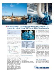
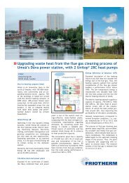
5 Unitop ® <strong>50FY</strong> <strong>heat</strong> <strong>pump</strong> / <strong>chiller</strong> <strong>units</strong> <strong>simultaneously</strong><br />
generate 90 MW <strong>heat</strong> energy and 60 MW chilled water<br />
Client<br />
Helsinki Energy<br />
00090 HELEN, Finland<br />
Helsinki is a fast growing area<br />
With a population of about 560,000<br />
inhabitants (Greater Helsinki area<br />
approx. 1.0 mil.), Helsinki is located<br />
at the sea in the southernmost part of<br />
Finland. In winter, ambient temperatures<br />
drop as low –25ºC for longer periods.<br />
In the summer, the climate is<br />
relatively warm and temperatures rise<br />
up to 25ºC or even higher.<br />
Helsinki Energy<br />
Helsinki Energy is one of the largest<br />
Finnish service companies in the energy<br />
sector. Customers are industrial and<br />
business enterprises, energy companies,<br />
municipalities, real estates and<br />
private consumers using electricity,<br />
district <strong>heat</strong>ing and district cooling.<br />
Helsinki Energy supplies electric energy<br />
to over 300,000 customers in different<br />
parts of Finland. Among the services<br />
provided are the design, projecting<br />
and maintenance of energy production<br />
and distribution systems. It produces<br />
and supplies district cooling energy<br />
and provides IT services to business<br />
buildings. With annual district <strong>heat</strong>ing<br />
sales exceeding 6,000 GWh and serving<br />
13,000 customer premises, most<br />
of which are residential buildings,<br />
Helsinki Energy is the largest energy<br />
company in Finland producing, distributing<br />
and selling district <strong>heat</strong>.<br />
1<br />
Helsinki Energy is a leading company<br />
for combined <strong>heat</strong> and power (CHP)<br />
Helsinki Energy produces district <strong>heat</strong><br />
effectively with combined <strong>heat</strong> and<br />
power production. Thus, the plants<br />
produce both electricity and <strong>heat</strong> with<br />
the highest possible efficiency, as opposed<br />
to separate electricity production,<br />
where the <strong>heat</strong>ing energy generated<br />
as a by-product is lead to the sea<br />
and lost.<br />
The CHP solution also offers a number<br />
of environmental benefits, including<br />
lower fuel use and controlled emissions.<br />
In Helsinki, CHP use typically results<br />
in a fuel consumption efficiency<br />
rate exceeding 90%.<br />
By comparison, an equivalent quantity<br />
of fuel used solely for generating electricity<br />
would result in a maximum fuel<br />
consumption efficiency rate of 40–50%.<br />
Helsinki Energy is one of the world’s<br />
leading CHP specialists, and Finland<br />
one of the leading countries in<br />
this field. Helsinki’s CHP-based dis-<br />
3<br />
trict <strong>heat</strong>ing system was awarded the<br />
United Nations Environmental Prize in<br />
1990 – and Helsinki Energy’s CHP and<br />
district <strong>heat</strong>ing expertise has been<br />
used in Korea, China, Japan, Canada,<br />
Britain, and Russia.<br />
Significant reduction of emissions<br />
Most of the <strong>heat</strong> energy in Helsinki is<br />
produced with natural gas. The use of<br />
natural gas creates no particle or sulphur<br />
emissions, and its carbon dioxide<br />
emissions are considerably lower than<br />
with other fossil fuels.<br />
The emissions from the power plants<br />
in Helsinki have reduced significantly<br />
since 1990. Dust emissions have been<br />
cut down by 89%, sulphur dioxide emissions<br />
by 82% and nitrogen oxide emissions<br />
by 72%. Emission reductions have<br />
been achieved mostly with combined<br />
production, use of natural gas and constantly<br />
refined production techniques.<br />
District <strong>heat</strong>ing...<br />
The move from individually <strong>heat</strong>ed<br />
buildings to centrally generated district<br />
<strong>heat</strong> began in the 1950s, and district<br />
<strong>heat</strong> now covers over 90% of the<br />
city’s infrastructure. Low individual<br />
chimneys have almost vanished from<br />
the urban landscape.<br />
The reliability of the district <strong>heat</strong>ing<br />
network is very high in Helsinki. It is<br />
2
designed with loops allowing distribution<br />
to customers via several alternative<br />
routes, if required. Looped networks<br />
increase distribution reliability<br />
considerably.<br />
The operation of Helsinki Energy’s<br />
district <strong>heat</strong>ing network is constantly<br />
monitored, limiting interruptions to a<br />
minimum.<br />
...and district cooling<br />
Since the late 1990s, Helsinki Energy is<br />
also constantly developing its district<br />
cooling system.<br />
One of the main reasons for the growing<br />
popularity of district cooling is<br />
seen in the increased concentration on<br />
core business activities of companies<br />
and subsequent outsourcing of building<br />
services. Another reason for the growing<br />
popularity of the service is its environmental<br />
friendliness and cost-effectiveness<br />
compared to conventional<br />
technology with local installed small<br />
air conditioning <strong>units</strong>.<br />
From Helsinki Energy’s point of view,<br />
district cooling also enhances the energy<br />
efficiency of CHP production even<br />
further. Along with electricity and district<br />
<strong>heat</strong> sales, district cooling constitutes<br />
a new form of energy service.<br />
Development of district cooling<br />
The capacity of the first district cooling<br />
plant located at the Salmisaari<br />
power plant is 10 MW. It consists of<br />
two absorption <strong>chiller</strong>s and a 1,000 m 3<br />
chilled water storage tank to cope with<br />
peak loads. Between the years<br />
2002-2006 another district cooling<br />
plant was built in the Salmisaari power<br />
plant area. The total capacity of this<br />
plant is 28 MW.<br />
The chilled water is distributed via the<br />
underground district cooling network<br />
to office and business buildings connected<br />
in the district of Ruoholahti.<br />
Since the year 2002, district cooling<br />
has been supplied to office buildings<br />
in the district of Hermanni and Vallila.<br />
Transportable cooling <strong>units</strong> produce<br />
the required cooling energy until a<br />
cooling plant and corresponding distribution<br />
network for district cooling are<br />
constructed in the area.<br />
Energy distribution tunnels<br />
Helsinki Energy operates close to 30 km<br />
of multi-utility tunnels excavated in<br />
bedrock. They contain water-, district<br />
<strong>heat</strong>ing- and district cooling pipelines,<br />
electric cables up to 110 kV as well as<br />
electric and telecommunication cables<br />
for domestic purposes. The size of the<br />
tunnels allows travelling by car.<br />
Due to the growing demand, Helsinki<br />
Energy has increased its district cooling<br />
production capacity significantly<br />
with the new Katri Vala installation.<br />
A distribution network is built to connect<br />
the city centre of Helsinki and the<br />
district of Sörnäinen to the new plant.<br />
Katri Vala combined district <strong>heat</strong>ing<br />
and district cooling plant<br />
In a rock cavern excavated beneath<br />
the Katri Vala Park in the Sörnäinen<br />
district of Helsinki, the <strong>heat</strong>-<strong>pump</strong><br />
plant is generating district <strong>heat</strong> of<br />
88ºC and <strong>simultaneously</strong> chilled water<br />
with a temperature of 4ºC for district<br />
cooling purposes.<br />
5 6<br />
Excavation work for the installation<br />
started in summer 2004 and the plant<br />
has been in commercial operation<br />
since autumn 2006.<br />
The Katri Vala installation is connected<br />
to the Suvilahti seawater <strong>pump</strong>ing<br />
station via a 600 m long multi-utility<br />
tunnel.<br />
“First, the seawater <strong>pump</strong>ing station<br />
will only serve the Katri Vala <strong>heat</strong><strong>pump</strong><br />
plant. By 2020, the <strong>pump</strong>ing station<br />
will also serve the future Suvilahti<br />
and Pasila district cooling plants” says<br />
Mr Veijo Noponen, who is a process<br />
designer and installation supervisor at<br />
Helen Engineering, a business unit of<br />
Helsinki Energy.<br />
4
7 8<br />
“In winter, the energy for district <strong>heat</strong>ing<br />
is extracted from treated domestic<br />
sewage flowing through the evaporators<br />
of the <strong>heat</strong> <strong>pump</strong>s, downstream of the<br />
Viikki sewage works and cold sea water<br />
is used for producing district cooling<br />
in free-cooling mode. In summer, the<br />
<strong>heat</strong> <strong>pump</strong>s produce <strong>heat</strong> continuously<br />
also in cooling mode. While the chilled<br />
water is completely absorbed by the<br />
district cooling system, the surplus<br />
<strong>heat</strong> energy is discharged into the sea<br />
water”, explains Mr. Noponen.<br />
New 10,000 m 3 chilled water storage<br />
facilities connected to the multi-utility<br />
tunnels are planned in the city<br />
centre. They are charged during the<br />
night when cooling energy sales are<br />
generally lower. The energy stored is<br />
used during the next day at peak load<br />
hours. The storage process enables the<br />
operation of the <strong>heat</strong> <strong>pump</strong>s at maximum<br />
efficiency.<br />
Five Unitop ® <strong>50FY</strong> <strong>heat</strong> <strong>pump</strong>s<br />
The Katri Vala installation comprises<br />
five electric-driven Unitop ® <strong>50FY</strong><br />
<strong>heat</strong> <strong>pump</strong>s leaving space for a sixth<br />
unit. Each <strong>heat</strong> <strong>pump</strong> consists of the<br />
Uniturbo ® <strong>50FY</strong> compressor with integrated<br />
lube- and seal oil systems, all<br />
factory assembled, completely piped<br />
and wired up and delivered to site as a<br />
single lift package. The high-efficiency<br />
<strong>heat</strong> exchanger package is also preassembled<br />
in the works. It consists of<br />
evaporator, condenser, subcooler and<br />
intermediate pressure vessel. Disman-<br />
10 11<br />
tled again, the package is supplied to<br />
site in various parts of still impressive<br />
size.<br />
Enhanced finned tubes of the latest design<br />
are used for optimal <strong>heat</strong> transfer<br />
and highest performance of the <strong>heat</strong><br />
exchangers. Materials are selected to<br />
perfectly match the requirements of<br />
the <strong>heat</strong> transfer fluids.<br />
Advanced plant control system<br />
The control and logic system is based<br />
on the latest Siemens PLC equipment<br />
designed especially for use in industrial<br />
environments. Each Unitop ® <strong>50FY</strong> <strong>heat</strong><br />
<strong>pump</strong> is equipped with its own PLC,<br />
touch screen, and is connected to the<br />
field components like pressure- and<br />
temperature sensors, actuators, electric<br />
motors, contactors and switches.<br />
The control and logic system is designed<br />
for fully automatic operation<br />
of the <strong>heat</strong> <strong>pump</strong> plant. For remote<br />
operation, a link is provided via Modebus<br />
to Helsinki energy’s main control<br />
room where operators monitor Helsinki’s<br />
whole district <strong>heat</strong>ing and district<br />
cooling networks.<br />
Flexibility for high energy efficiency<br />
Unitop ® <strong>50FY</strong> <strong>chiller</strong>s offer all imaginable<br />
flexibility regarding use of <strong>heat</strong><br />
sources. Picture no. 12 shows the integration<br />
of the Unitop ® <strong>50FY</strong> <strong>heat</strong> <strong>pump</strong><br />
at Katri Vala.<br />
Winter operation<br />
The temperature of the sewage is<br />
higher than the seawater temperature,<br />
resulting in a favourable COP of the<br />
<strong>heat</strong> <strong>pump</strong>. (Valves B, C+ D open, Valve<br />
A closed). The district <strong>heat</strong>ing water<br />
is pre<strong>heat</strong>ed only by the <strong>heat</strong> <strong>pump</strong> to<br />
62°C, thus further enhancing the overall<br />
COP. The <strong>heat</strong> energy generated is completely<br />
absorbed by the district <strong>heat</strong>ing<br />
network, while the district cooling demand<br />
is covered by using cold seawater<br />
in “free cooling” mode. (Valves G open,<br />
valves E, F + H closed).<br />
Summer operation<br />
There is a considerably smaller demand<br />
of <strong>heat</strong> energy during the warm season.<br />
9
Thus, the Unitop ® <strong>50FY</strong> <strong>heat</strong> <strong>pump</strong>s are<br />
able to produce the full temperature<br />
lift required. The chilled water produced<br />
is absorbed completely by the<br />
district cooling system. During times<br />
without <strong>heat</strong> load, the condensing<br />
temperature is lowered to match with<br />
sea water conditions and the <strong>heat</strong>ing<br />
energy is rejected to the sea, resulting<br />
in a very high COP. (Valves A + H open,<br />
Valve B + C closed, Valves E + F open,<br />
Valves D + G closed).<br />
Main features of the Unitop ® <strong>50FY</strong><br />
• Open-type two stage compressor<br />
• Refrigerants: halocarbon/hydrocarbon<br />
• Tough industrial design with vertically<br />
split casing for easy maintenance<br />
• Suited for all drive systems<br />
• High efficiency across the entire<br />
operating range<br />
• Operating temperatures –40°C/+90°C<br />
• Operation in series or in parallel<br />
• Large capacity, small floor space<br />
Service and maintenance<br />
Specialists of Helsinki Energy are maintaining<br />
the Unitop ® <strong>50FY</strong> <strong>heat</strong> <strong>pump</strong><br />
during normal operation. Under a special<br />
agreement, <strong>Friotherm</strong> carries out<br />
the regular service works on the five<br />
<strong>heat</strong> <strong>pump</strong>s.<br />
E012-07 Subject to technical change<br />
Technical data:<br />
5 Heat Pump Unitop ® <strong>50FY</strong>, each<br />
Winter operation:<br />
Heating capacity 16,770 kW<br />
Heating water flow 1,221 m 3 /h<br />
Inlet/outlet temperature 50/62 °C<br />
Power absorbed 4,770 kW<br />
Electric motor 6,500 kW<br />
Voltage 11 kV<br />
Heat source (cooling) capacity 12,000 kW<br />
Sewage in/out temp. 10/4 °C<br />
Summer operation:<br />
Heating capacity 18,113 kW<br />
Heating water flow 370 m 3 /h<br />
Inlet/outlet temperature 45/88 °C<br />
Power absorbed 6,113 kW<br />
Electric motor 6,500 kW<br />
Voltage 11 kV<br />
Heat source (cooling) capacity 12,000 kW<br />
District cooling in/out temp. 20/4 °C<br />
Legend<br />
1 View of the harbour area and the city<br />
centre of Helsinki.<br />
2 The Hanasaari combined <strong>heat</strong> and power<br />
plant. The Suvilahti seawater <strong>pump</strong>ing<br />
station is located in the flat roofed<br />
brick building on the left.<br />
3 The only smoking chimneys on a cold<br />
winter day are the ones of the Helsinki<br />
Energy’s power plants. They cover more<br />
than 90 percent of the <strong>heat</strong> demand of<br />
the capital city with district <strong>heat</strong><br />
4 A Unitop ® <strong>50FY</strong> <strong>heat</strong> <strong>pump</strong> unit at right,<br />
with district <strong>heat</strong>ing <strong>pump</strong>s and piping<br />
in the centre, towards the end of erection.<br />
5 Helsinki Energy is developing its networks<br />
for district <strong>heat</strong>ing and district<br />
cooling at great speed to match with<br />
the increasing demand.<br />
6 The Katri Vala park is located between<br />
the city center and the harbour area<br />
with the Hanasaari power station.<br />
7 Main entrance door to the district <strong>heat</strong>ing<br />
/ cooling plant located below the<br />
Katri Vala park.<br />
8 One of the three service tunnels of the<br />
Katri Vala plant. Each Unitop ® <strong>50FY</strong> is<br />
placed in a cavern, isolated from the<br />
other <strong>units</strong>.<br />
9 Operating staff member next to a Unitop<br />
® <strong>50FY</strong> <strong>heat</strong> <strong>pump</strong> unit. Right: Compressor<br />
and motor; centre: the seal oil<br />
package; back: the <strong>heat</strong> exchangers.<br />
10 3D-view of the Unitop ® <strong>50FY</strong>. Left:<br />
motor, gear, compressor and oil system.<br />
Right: the <strong>heat</strong> exchanger package.<br />
11 Sample screen of the touch panel with<br />
user friendly setup of the control system<br />
for each Unitop ® <strong>50FY</strong> <strong>heat</strong> <strong>pump</strong> unit.<br />
12 Simplified functional diagram of the<br />
Katri Vala district <strong>heat</strong>ing / district<br />
cooling systems, utilising sewage and<br />
sea water as <strong>heat</strong> sources.<br />
<strong>Friotherm</strong> AG<br />
Zürcherstrasse 12 · P.O.Box 414<br />
CH-8400 Winterthur · Switzerland<br />
Tel. +41 (0) 52 2 62-80 80 · Fax -00 03<br />
E-Mail info@friotherm.com<br />
Internet www.friotherm.com<br />
12