DH6/10
DH6/10 DH6/10
Pilot operated check valve (1) Sub-plate Valve type Sub-plate type Connection diameter Mass When you use a sub-plate, please place an order for the above sub-plate type. For the dimension drawing, refer to pages 6 and 7 of the appendix. Accessories Mounting bolt Type Hexagon socket head cap thread Quantity Tightening torque Nm (kgfcm) Pressure drop characteristics (viscosity 36 mm 2 /s (cSt)) CH/CHY6810 CH1520CHY15 CHY20P Amount of pressure drop (MPa Flow rate (L/min) Amount of pressure drop (MPa Flow rate (L/min) CHY2530CHY20G(R) CH2530 Amount of pressure drop (MPa Flow rate (L/min) Precautions in use Method of obtaining minimum required pilot pressure (refer to symbols in the structural drawing) In the case of CH In the case of CHY A2: Pressure receiving area of lifting piston (cm 2 ) A3: Pressure receiving area of lifting piston rod (cm 2 ) Nominal dimension Method of using internal drain type and external drain type When port A is directly connected to the tank during reverse free flow, the internal drain type is generally used. However, if back pressure is applied to port A, be sure to use the external drain type. Pst: Minimum required pilot pressure (MPa) P1: Load pressure (pressure of port B) (MPa) P2: Back pressure (pressure of port A) (MPa) A1: Pressure receiving area of poppet (cm 2 ) (Note) For minimum required pilot pressure (Pst), low pilot operated check valves for pilot pressure lower than Pst obtained from the above (pilot pressure equivalent to approximately 1/8 of load pressure) are also available (KSV/KSL type). If you need the above valve, please contact us. 1-74
Y B A B A X X ■Dimension drawing ●CH/CHY (G screw connection type) F 2 Q CH*G 1 C C M N G 2-φD 2-E A 15 1 X B In the case of 6 to 10 only G1/4 H J φ25 K L 51.5 (54.5 in the case of 10) G 2-φD 2-E 1 Q A Y CHY*G X Y B 15 1 P Y B A B A X X C G1/4 (both X and Y ports) In the case of 15 to 30 only H J 70.5 φ25 K L Pilot operated check valve (1) 2-φ11 through hole A B 2-φ11 through hole A B Type Nominal dimension 6 A 66.5 B C D E F G H J K L M N 85 40 25 G 1 4 42 27.5 18.5 10.5 33.5 49 80 116 P 18 Q 15 8 66.5 85 40 32 G 3 8 42 27.5 18.5 10.5 33.5 49 80 116 18 15 CH 10 15 66.5 79.5 85 100 40 58 38 45 G 1 2 G 3 4 42 60 27.5 36.5 18.5 17.5 10.5 13 33.5 50.5 49 65.5 80 95 116 135 18 20 16 17 20 25 79.5 97 100 120 58 52 73 63 G 1 G1 1 4 60 75 36.5 54.5 17.5 15.5 13 20.5 50.5 71.5 65.5 87.5 95 115 135 173 20 29 18 24 30 97 120 73 65 G1 1 2 75 54.5 15.5 20.5 71.5 87.5 115 173 29 24 6 66.5 85 40 25 G 1 4 42 23.5 16.5 12.5 35.5 51 80 116 18 15 8 66.5 85 40 32 G 3 8 42 19 16.5 12.5 35.5 51 80 116 18 15 10 66.5 85 40 38 G 1 2 42 19.5 13.5 15.5 38.5 54 80 116 18 16 CHY 15 20 74 74 120 120 73 73 45 52 G 3 4 G 1 75 75 54.5 54.5 15.5 15.5 20.5 18 84 84 97.5 97.5 125 125 183 183 29 29 17 18 25 30 74 74 120 120 73 73 63 65 G1 1 4 G1 1 2 75 75 54.5 54.5 15.5 15.5 18 18 84 84 97.5 97.5 125 125 183 183 29 29 24 24 ●CH/CHY (R screw connection type) C E A 2 L M 2-D (both A and B ports) F A CH*R X B A Y CHY*R In the case of 6 to 10 only Q 12.5 Q 12.5 C Rc1/4 H J K 2-D (both A and B ports) P F C X Y B H Rc1/4 (both X and Y ports) 70.5 In the case of 15 to 30 only J N G K G 2-φ11 through hole A B 2-φ11 through hole A B Type Nominal dimension 6 A 66.5 B C D E F G H J K L M N 85 40 Rc 1 4 42 27.5 18.5 10.5 33.5 49 80 116 18 P ー Q 12.5 8 66.5 85 40 Rc 3 8 42 27.5 18.5 10.5 33.5 49 80 116 18 ー 14 CH 10 15 66.5 79.5 85 100 40 58 Rc 1 2 Rc 3 4 42 60 27.5 36.5 18.5 17.5 10.5 13 33.5 50.5 49 65.5 80 95 116 135 18 20 ー ー 17 19 20 25 79.5 97 100 120 58 73 Rc 1 Rc1 1 4 60 75 36.5 54.5 17.5 15.5 13 20.5 50.5 71.5 65.5 87.5 95 115 135 173 20 29 ー ー 22 24.5 30 97 120 73 Rc1 1 2 75 54.5 15.5 20.5 71.5 87.5 115 173 29 ー 25.5 6 66.5 85 40 Rc 1 4 42 23.5 16.5 12.5 35.5 51 80 116 18 51.5 12.5 8 66.5 85 40 Rc 3 8 42 19 16.5 12.5 35.5 51 80 116 18 51.5 14 10 66.5 85 40 Rc 1 2 42 19.5 13.5 15.5 38.5 54 80 116 18 54.5 17 CHY 15 20 74 74 120 120 73 73 Rc 3 4 Rc 1 75 75 54.5 54.5 15.5 15.5 20.5 18 84 84 97.5 97.5 125 125 183 183 29 29 ー ー 19 22 25 30 74 74 120 120 73 73 Rc1 1 4 Rc1 1 2 75 75 54.5 54.5 15.5 15.5 18 18 84 84 97.5 97.5 125 125 183 183 29 29 ー ー 24.5 25.5 1-75
- Page 30 and 31: Solenoid controlled pilot operated
- Page 32 and 33: Solenoid controlled pilot operated
- Page 34 and 35: Solenoid controlled pilot operated
- Page 36 and 37: Solenoid controlled pilot operated
- Page 38 and 39: Solenoid controlled pilot operated
- Page 40 and 41: Solenoid controlled pilot operated
- Page 42 and 43: Solenoid controlled pilot operated
- Page 44 and 45: Solenoid controlled pilot operated
- Page 46 and 47: Pilot operated directional valve (1
- Page 48 and 49: Pilot operated directional valve (1
- Page 50 and 51: Pilot operated directional valve (2
- Page 52 and 53: Pilot operated directional valve (2
- Page 54 and 55: Pilot operated directional valve (2
- Page 56 and 57: Pilot operated directional valve (3
- Page 58 and 59: Pilot operated directional valve (3
- Page 60 and 61: Pilot operated directional valve (3
- Page 62 and 63: Manual selector valve (1) Spool typ
- Page 64 and 65: Manual selector valve (1) ■Dimens
- Page 66 and 67: Manual selector valve (2) Spool typ
- Page 68 and 69: Manual selector valve (2) ■Dimens
- Page 70 and 71: Manual selector valve - KLA type Ma
- Page 72 and 73: Check valve (1) ■Specifications N
- Page 74 and 75: Check valve (1) ●C (cartridge typ
- Page 76 and 77: Amount of pressure drop (MPa Check
- Page 78 and 79: 45° Check valve (2) ●C (flange c
- Page 82 and 83: A Y B X Pilot operated check valve
- Page 84 and 85: Pilot operated check valve (2) Flan
- Page 86 and 87: Pressure gauge valve Pressure gauge
- Page 88 and 89: Page Relief valve - Direct operated
- Page 90 and 91: Hydraulic symbols Pressure increase
- Page 92 and 93: Pressure override characteristics (
- Page 94 and 95: Dimension drawing RD*G/R RDV6G/R L2
- Page 96 and 97: RDV1M6R A 62 Maximum of 152 61 14.5
- Page 98 and 99: Type indication RBE Relief valve -
- Page 100 and 101: Pilot valve The type indication of
- Page 102 and 103: Dimension drawing RB*P B1 B2 X P T
- Page 104 and 105: Relief valve - Balanced piston type
- Page 106 and 107: Type indication RB35X Pilot relief
- Page 108 and 109: RB35F 38 19 110 Y port G1/4 screw d
- Page 110 and 111: Type indication RB52 Relief valve-
- Page 112 and 113: Pilot valve The type indication of
- Page 114 and 115: Three stage pressure relief valve 3
- Page 116 and 117: Dimension drawing 3RBE L10 L1 L8 L3
- Page 118 and 119: Pressure override characteristics (
- Page 120 and 121: PUE Pilot operated unloading relief
- Page 122 and 123: Dimension drawing PU10 47.1 85 66.7
- Page 124 and 125: Pilot operated unloading relief val
- Page 126 and 127: Dimension drawing PU35P (Gasket con
- Page 128 and 129: Specifications SD6P SD10P P-DE6R14-
Pilot operated check valve (1)<br />
Sub-plate<br />
Valve type Sub-plate type Connection diameter Mass<br />
<br />
<br />
<br />
<br />
<br />
<br />
<br />
<br />
<br />
<br />
<br />
<br />
<br />
<br />
<br />
<br />
<br />
<br />
<br />
<br />
<br />
<br />
<br />
<br />
<br />
<br />
<br />
<br />
<br />
<br />
<br />
<br />
<br />
<br />
<br />
<br />
<br />
<br />
When you use a sub-plate, please place an order for the above sub-plate type.<br />
For the dimension drawing, refer to pages 6 and 7 of the appendix.<br />
Accessories<br />
Mounting bolt<br />
Type Hexagon <br />
socket head cap thread Quantity Tightening torque Nm (kgfcm)<br />
<br />
<br />
<br />
<br />
<br />
<br />
<br />
<br />
<br />
<br />
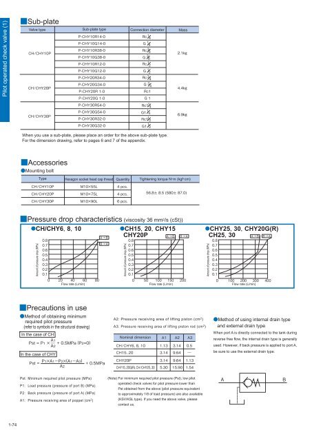
Pressure drop characteristics (viscosity 36 mm 2 /s (cSt))<br />
CH/CHY68<strong>10</strong><br />
CH1520CHY15<br />
CHY20P<br />
Amount of pressure drop (MPa<br />
<br />
<br />
<br />
<br />
<br />
<br />
<br />
<br />
<br />
<br />
Flow rate (L/min)<br />
<br />
<br />
<br />
<br />
<br />
<br />
<br />
<br />
<br />
<br />
<br />
Amount of pressure drop (MPa<br />
<br />
<br />
Flow rate (L/min)<br />
CHY2530CHY20G(R)<br />
CH2530<br />
<br />
<br />
<br />
<br />
<br />
<br />
<br />
<br />
<br />
Amount of pressure drop (MPa<br />
<br />
<br />
Flow rate (L/min)<br />
Precautions in use<br />
Method of obtaining minimum<br />
required pilot pressure<br />
(refer to symbols in the structural drawing)<br />
In the case of CH<br />
<br />
<br />
<br />
<br />
In the case of CHY<br />
<br />
<br />
<br />
A2: Pressure receiving area of lifting piston (cm 2 )<br />
A3: Pressure receiving area of lifting piston rod (cm 2 )<br />
<br />
Nominal dimension<br />
<br />
<br />
<br />
<br />
<br />
<br />
<br />
<br />
<br />
<br />
<br />
<br />
<br />
<br />
<br />
<br />
<br />
Method of using internal drain type<br />
and external drain type<br />
When port A is directly connected to the tank during<br />
reverse free flow, the internal drain type is generally<br />
used. However, if back pressure is applied to port A,<br />
be sure to use the external drain type.<br />
Pst: Minimum required pilot pressure (MPa)<br />
P1: Load pressure (pressure of port B) (MPa)<br />
P2: Back pressure (pressure of port A) (MPa)<br />
A1: Pressure receiving area of poppet (cm 2 )<br />
(Note) For minimum required pilot pressure (Pst), low pilot<br />
operated check valves for pilot pressure lower than<br />
Pst obtained from the above (pilot pressure equivalent<br />
to approximately 1/8 of load pressure) are also available<br />
(KSV/KSL type). If you need the above valve, please<br />
contact us.<br />
<br />
<br />
1-74


