DH6/10
DH6/10 DH6/10
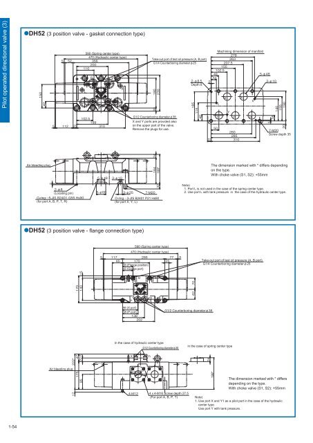
Pilot operated directional valve (3) DH52 (3 position valve - gasket connection type) 590 (Spring center type) 470 (Hydraulic center type) Machining dimension of manifold Take-out port of test oil pressure (A, B port) G1/4 Counterboring diameter25 Depth 8 G1/2 Counterboring diameter38 X and Y ports are provided also on the upper part of the valve. Remove the plugs for use. Screw depth 35 Air bleeding plug 188* The dimension marked with * differs depending on the type. With choke valve (S1, S2): +55mm (Locating pin) O-ring (for port A, B, P, T, R) O-ring3-JIS B2401 P21 Hs90 (for port X, Y, L) Note) 1. Port L is not used in the case of the spring center type. 2. Use port L with tank pressure in the case of the hydraulic center type. DH52 (3 position valve - flange connection type) 590 (Spring center type) 470 (Hydraulic center type) 66 (Flange position) 65 (Gauge port) Take-out port of test oil pressure (A, B port) G1/4 Counterboring diameter25 96 (X port) 98 (P port) G1/2 Counterboring diameter38 In the case of hydraulic center type G1/2 Counterboring diameter38 in the case of spring center type * Air bleeding plug 44-M16 Screw depth 27.5 (For port A, B, P, T) 199* The dimension marked with * differs depending on the type. With choke valve (S1, S2): +55mm Note) 1. Use port X and Y1 as a pilot port in the case of the hydraulic center type. Use port Y with tank pressure. 1-54
Manual selector valve (1) Spring center type Manual selector valve (1) Overview This manual selector valve is used for controlling start and stop, and movement direction of the hydraulic system with handle operation. Type indication Manual selector valve Nominal dimension Connection method Gasket connection type Series number: 10 Position holding method 1 = No spring type, detent type 2 = Spring offset type Spring center type Type of hydraulic oil No symbol Mineral based hydraulic oil V Phosphate ester based hydraulic oil W Fatty ester based hydraulic oil Water-glycol based hydraulic oil Presence/absence of P port restriction No symbol = No restriction P08 = Restriction contraction diameterφ0.8mm P10 = Restriction contraction diameterφ1.0mm P12 = Restriction contraction diameterφ1.2mm Spool type * Refer to “Spool type symbols”. Specifications Maximum working pressure (Note 1) MPa (kgf/cm 2 ) Mass kg Nominal dimension Port A, B, P Port T Operating force during switching N (kgf) 30.9 (315) 2.9 (30) 14.7 (150) 19.6 to 29.4 (2.0 to 3.0) 15.7 to 26.5 (1.6 to 2.7) Sub-plate Valve type Sub-plate type Connection diameter Mass (Note 1) If working pressure exceeds the highest pressure of port T when the spool type is A or B, use port T as a drain port. ● The opening area at spool neutral position is “spool type 23 = 3%, spool type 17 = 6%” when spool type 10 is assumed to be 100%. Accessories Mounting bolt Type Hexagon socket head cap thread Quantity Tightening torque Nm (kgfcm) 4 pcs. () When you use a sub-plate, please place an order for the above sub-plate type. For the dimension drawing, refer to pages 9 and 11 of the appendix. 4 pcs. () 1-55
- Page 10 and 11: Solenoid operated directional valve
- Page 12 and 13: Solenoid operated directional valve
- Page 14 and 15: Solenoid operated directional valve
- Page 16 and 17: Solenoid operated directional valve
- Page 18 and 19: Solenoid operated directional valve
- Page 20 and 21: Solenoid operated directional valve
- Page 22 and 23: Solenoid operated directional valve
- Page 24 and 25: Solenoid operated directional valve
- Page 26 and 27: Solenoid controlled pilot operated
- Page 28 and 29: Solenoid controlled pilot operated
- Page 30 and 31: Solenoid controlled pilot operated
- Page 32 and 33: Solenoid controlled pilot operated
- Page 34 and 35: Solenoid controlled pilot operated
- Page 36 and 37: Solenoid controlled pilot operated
- Page 38 and 39: Solenoid controlled pilot operated
- Page 40 and 41: Solenoid controlled pilot operated
- Page 42 and 43: Solenoid controlled pilot operated
- Page 44 and 45: Solenoid controlled pilot operated
- Page 46 and 47: Pilot operated directional valve (1
- Page 48 and 49: Pilot operated directional valve (1
- Page 50 and 51: Pilot operated directional valve (2
- Page 52 and 53: Pilot operated directional valve (2
- Page 54 and 55: Pilot operated directional valve (2
- Page 56 and 57: Pilot operated directional valve (3
- Page 58 and 59: Pilot operated directional valve (3
- Page 62 and 63: Manual selector valve (1) Spool typ
- Page 64 and 65: Manual selector valve (1) ■Dimens
- Page 66 and 67: Manual selector valve (2) Spool typ
- Page 68 and 69: Manual selector valve (2) ■Dimens
- Page 70 and 71: Manual selector valve - KLA type Ma
- Page 72 and 73: Check valve (1) ■Specifications N
- Page 74 and 75: Check valve (1) ●C (cartridge typ
- Page 76 and 77: Amount of pressure drop (MPa Check
- Page 78 and 79: 45° Check valve (2) ●C (flange c
- Page 80 and 81: Pilot operated check valve (1) Sub-
- Page 82 and 83: A Y B X Pilot operated check valve
- Page 84 and 85: Pilot operated check valve (2) Flan
- Page 86 and 87: Pressure gauge valve Pressure gauge
- Page 88 and 89: Page Relief valve - Direct operated
- Page 90 and 91: Hydraulic symbols Pressure increase
- Page 92 and 93: Pressure override characteristics (
- Page 94 and 95: Dimension drawing RD*G/R RDV6G/R L2
- Page 96 and 97: RDV1M6R A 62 Maximum of 152 61 14.5
- Page 98 and 99: Type indication RBE Relief valve -
- Page 100 and 101: Pilot valve The type indication of
- Page 102 and 103: Dimension drawing RB*P B1 B2 X P T
- Page 104 and 105: Relief valve - Balanced piston type
- Page 106 and 107: Type indication RB35X Pilot relief
- Page 108 and 109: RB35F 38 19 110 Y port G1/4 screw d
Pilot operated directional valve (3)<br />
DH52 (3 position valve - gasket connection type)<br />
<br />
<br />
<br />
<br />
<br />
<br />
<br />
590 (Spring center type)<br />
470 (Hydraulic center type)<br />
<br />
<br />
<br />
<br />
<br />
<br />
<br />
<br />
<br />
<br />
<br />
<br />
<br />
<br />
<br />
Machining dimension of manifold<br />
<br />
Take-out port of test oil pressure (A, B port)<br />
<br />
G1/4 Counterboring diameter25<br />
<br />
<br />
<br />
<br />
<br />
<br />
<br />
<br />
Depth 8<br />
<br />
<br />
<br />
G1/2 Counterboring diameter38<br />
X and Y ports are provided also<br />
on the upper part of the valve.<br />
Remove the plugs for use.<br />
<br />
<br />
<br />
<br />
<br />
<br />
<br />
<br />
<br />
<br />
<br />
<br />
<br />
<br />
<br />
<br />
<br />
<br />
<br />
<br />
<br />
<br />
<br />
Screw depth 35<br />
<br />
Air bleeding plug<br />
<br />
<br />
<br />
188*<br />
The dimension marked with * differs depending<br />
on the type.<br />
With choke valve (S1, S2): +55mm<br />
<br />
<br />
(Locating pin)<br />
O-ring<br />
(for port A, B, P, T, R)<br />
<br />
<br />
<br />
O-ring3-JIS B2401 P21 Hs90<br />
(for port X, Y, L)<br />
Note)<br />
1. Port L is not used in the case of the spring center type.<br />
2. Use port L with tank pressure in the case of the hydraulic center type.<br />
DH52 (3 position valve - flange connection type)<br />
590 (Spring center type)<br />
470 (Hydraulic center type)<br />
<br />
<br />
<br />
<br />
<br />
66 (Flange position)<br />
65 (Gauge port)<br />
Take-out port of test oil pressure (A, B port)<br />
G1/4 Counterboring diameter25<br />
<br />
<br />
<br />
<br />
<br />
<br />
<br />
96 (X port)<br />
98 (P port)<br />
<br />
<br />
<br />
<br />
<br />
G1/2 Counterboring diameter38<br />
In the case of hydraulic center type<br />
G1/2 Counterboring diameter38<br />
in the case of spring center type<br />
*<br />
<br />
<br />
<br />
<br />
<br />
Air bleeding plug<br />
<br />
<br />
<br />
<br />
<br />
44-M16 Screw depth 27.5<br />
(For port A, B, P, T)<br />
199*<br />
The dimension marked with * differs<br />
depending on the type.<br />
With choke valve (S1, S2): +55mm<br />
Note)<br />
1. Use port X and Y1 as a pilot port in the case of the hydraulic<br />
center type.<br />
Use port Y with tank pressure.<br />
1-54


