DH6/10
DH6/10 DH6/10
Pilot operated directional valve (2) ■Specifications Maximum working pressure MPa (kgf/cm 2 ) Highest pilot pressure MPa (kgf/cm 2 ) Lowest pilot pressure MPa (kgf/cm 2 ) Stroke volume of pilot part cm 3 Mass kg Nominal dimension 16 22 32 Port A, B, P Port T Opening area at spool neutral position (with spool 10 as 100%) 3 position valve spring center type 3 position valve hydraulic center type 2 position valve spring offset type 2 position valve hydraulic offset type 2 position valve spring offset type 2 position valve hydraulic offset type 3 position valve spring center type 3 position valve hydraulic center type Position “o”→“a” Position “a”→“o” Position “o”→“b” Position “b”→“o” Spool 17, 22 Spool 23 34.3 (350) 24.5 (250) 24.5 (250) 0.78 (8.0) 0.98 (10.0) 0.5(5.0) 8.9 19.3 70.7 4.45 9.65 35.35 2.30 5.0 17.25 2.15 4.65 18.1 4.45 9.65 35.35 2.30 4.65 16% 3% 17.25 7.5 13 49 ■Maximum flow rate Maximum flow rate L/min 2 position valve spring offset type 3 position valve spring center type Nominal dimension Spool type Working pressure MPa (kgf/cm 2 ) 7 (70) 14 (140) 20.6 (210) 27.4 (280) 34.3 (350) (A) 16 05, 10, 12, 13, 17, 18, 21 22, 23, 03, 04, 11, 26 06 * 240 200 240 145 205 115 180 100 170 90 07, 08, 19, 20 220 160 130 110 100 (A) 22 05, 10, 12, 13, 17, 18, 21 22, 23, 03, 04, 11, 26 * 450 450 370 320 300 06, 07, 08, 19, 20 360 250 210 180 160 (A) 32 05., 10, 12, 13, 17, 18, 21 22, 23, 03, 04, 11, 26 * 1100 1050 860 750 680 06, 07, 08, 19, 20 820 630 510 450 400 (Note) ● The above table shows numerical values in the case of the lowest pilot pressure. ● The maximum flow rate in the case of the 2 position valve hydraulic offset type and 3 position valve hydraulic center type is the flow rate of stage (A) regardless of the spool type, and is the flow rate marked with * regardless of the spool type and pressure if pilot pressure is 1.5 MPa (15 Kgf/cm 2 ) or higher. ■Pressure drop characteristics ● Similar to those of solenoid controlled pilot operated directional valve (DEH16, 22, 32) Refer to the section of the type number index “DEH16, 22, 32”. 1-46
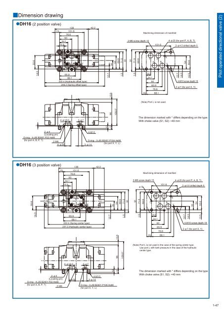
Dimension drawing DH16 (2 position valve) 222.4 (Hydraulic offset type) 248.2 (Spring offset type) Machining dimension of manifold 2-M6 screw depth 15 4-20 (for port P, A, B, T) 2-4.5 drilled depth 5 4-M10 screw depth 18 2-7 (for port X, Y) Pilot operated directional valve (2) (Note) Port L is not used. DH16 (3 position valve) * 222.4 (Spring center type) 237.2 (Hydraulic center type) (Note) Port L is not used in the case of the spring center type. Use port L with tank pressure in the case of the hydraulic center type. * The dimension marked with * differs depending on the type. With choke valve (S1, S2): +40 mm (Locating pin) O-ring4-JIS B2401 P22 Hs90 (for port A, B, P, T) O-ring3-JIS B2401 P10A Hs90 (for port X, Y, L) Machining dimension of manifold 2-M6 screw depth 15 4-20 (for port P, A, B, T) 2-4.5 drilled depth 5 4-M10 screw depth 18 2-7 (for port X, Y) (Locating pin) O-ring4-JIS B2401 P22 Hs90 (for port A, B, P, T) O-ring3-JIS B2401 P10A Hs90 (for port X, Y, L) The dimension marked with * differs depending on the type. With choke valve (S1, S2): +40 mm 1-47
- Page 2 and 3: Oil Pressure Regulating Valve In ad
- Page 4 and 5: Safety Precautions Cautions concern
- Page 6 and 7: L LPR16 to 63 (Logic element for pr
- Page 8 and 9: Solenoid operated directional valve
- Page 10 and 11: Solenoid operated directional valve
- Page 12 and 13: Solenoid operated directional valve
- Page 14 and 15: Solenoid operated directional valve
- Page 16 and 17: Solenoid operated directional valve
- Page 18 and 19: Solenoid operated directional valve
- Page 20 and 21: Solenoid operated directional valve
- Page 22 and 23: Solenoid operated directional valve
- Page 24 and 25: Solenoid operated directional valve
- Page 26 and 27: Solenoid controlled pilot operated
- Page 28 and 29: Solenoid controlled pilot operated
- Page 30 and 31: Solenoid controlled pilot operated
- Page 32 and 33: Solenoid controlled pilot operated
- Page 34 and 35: Solenoid controlled pilot operated
- Page 36 and 37: Solenoid controlled pilot operated
- Page 38 and 39: Solenoid controlled pilot operated
- Page 40 and 41: Solenoid controlled pilot operated
- Page 42 and 43: Solenoid controlled pilot operated
- Page 44 and 45: Solenoid controlled pilot operated
- Page 46 and 47: Pilot operated directional valve (1
- Page 48 and 49: Pilot operated directional valve (1
- Page 50 and 51: Pilot operated directional valve (2
- Page 54 and 55: Pilot operated directional valve (2
- Page 56 and 57: Pilot operated directional valve (3
- Page 58 and 59: Pilot operated directional valve (3
- Page 60 and 61: Pilot operated directional valve (3
- Page 62 and 63: Manual selector valve (1) Spool typ
- Page 64 and 65: Manual selector valve (1) ■Dimens
- Page 66 and 67: Manual selector valve (2) Spool typ
- Page 68 and 69: Manual selector valve (2) ■Dimens
- Page 70 and 71: Manual selector valve - KLA type Ma
- Page 72 and 73: Check valve (1) ■Specifications N
- Page 74 and 75: Check valve (1) ●C (cartridge typ
- Page 76 and 77: Amount of pressure drop (MPa Check
- Page 78 and 79: 45° Check valve (2) ●C (flange c
- Page 80 and 81: Pilot operated check valve (1) Sub-
- Page 82 and 83: A Y B X Pilot operated check valve
- Page 84 and 85: Pilot operated check valve (2) Flan
- Page 86 and 87: Pressure gauge valve Pressure gauge
- Page 88 and 89: Page Relief valve - Direct operated
- Page 90 and 91: Hydraulic symbols Pressure increase
- Page 92 and 93: Pressure override characteristics (
- Page 94 and 95: Dimension drawing RD*G/R RDV6G/R L2
- Page 96 and 97: RDV1M6R A 62 Maximum of 152 61 14.5
- Page 98 and 99: Type indication RBE Relief valve -
- Page 100 and 101: Pilot valve The type indication of
Dimension drawing<br />
DH16 (2 position valve)<br />
<br />
<br />
<br />
<br />
<br />
<br />
<br />
<br />
<br />
<br />
<br />
<br />
<br />
<br />
<br />
222.4 (Hydraulic offset type)<br />
248.2 (Spring offset type)<br />
<br />
<br />
<br />
<br />
<br />
<br />
<br />
<br />
Machining dimension of manifold<br />
2-M6 screw depth 15<br />
4-20 (for port P, A, B, T)<br />
<br />
<br />
<br />
<br />
<br />
<br />
<br />
<br />
<br />
<br />
<br />
<br />
2-4.5 drilled depth 5<br />
<br />
<br />
<br />
<br />
4-M<strong>10</strong> screw depth 18<br />
2-7 (for port X, Y)<br />
Pilot operated directional valve (2)<br />
<br />
<br />
<br />
(Note) Port L is not used.<br />
<br />
<br />
<br />
<br />
DH16 (3 position valve)<br />
<br />
<br />
<br />
<br />
<br />
<br />
<br />
<br />
<br />
<br />
<br />
<br />
<br />
<br />
<br />
*<br />
<br />
<br />
<br />
<br />
<br />
<br />
<br />
<br />
222.4 (Spring center type)<br />
237.2 (Hydraulic center type)<br />
<br />
<br />
<br />
<br />
<br />
(Note) Port L is not used in the case of the spring center type.<br />
Use port L with tank pressure in the case of the hydraulic<br />
center type.<br />
<br />
<br />
<br />
<br />
*<br />
The dimension marked with * differs depending on the type.<br />
With choke valve (S1, S2): +40 mm<br />
<br />
(Locating pin)<br />
O-ring4-JIS B2401 P22 Hs90<br />
(for port A, B, P, T)<br />
<br />
<br />
<br />
O-ring3-JIS B2401 P<strong>10</strong>A Hs90<br />
(for port X, Y, L)<br />
<br />
Machining dimension of manifold<br />
2-M6 screw depth 15<br />
4-20 (for port P, A, B, T)<br />
<br />
<br />
2-4.5 drilled depth 5<br />
<br />
<br />
<br />
<br />
<br />
<br />
<br />
<br />
<br />
<br />
<br />
<br />
<br />
<br />
<br />
<br />
<br />
<br />
<br />
<br />
<br />
<br />
4-M<strong>10</strong> screw depth 18<br />
2-7 (for port X, Y)<br />
<br />
<br />
<br />
<br />
<br />
<br />
(Locating pin)<br />
O-ring4-JIS B2401 P22 Hs90<br />
(for port A, B, P, T)<br />
<br />
<br />
<br />
<br />
<br />
O-ring3-JIS B2401 P<strong>10</strong>A Hs90<br />
(for port X, Y, L)<br />
<br />
The dimension marked with * differs depending on the type.<br />
With choke valve (S1, S2): +40 mm<br />
1-47


