DH6/10
DH6/10 DH6/10
■Dimension drawing 10 ●PRBP 20 P-10/*-E 30 B C L6 L5 L4 φ6 φ13 depth of counter bore 1.4 K Y 2-φD1 φD2 depth of counter bore H6 B 1 B 2 B A 45 X J1 J2 L7 L8 J3 L2 MAX.L1 In case of electric connection symbol C (DIN large connector GDME3011) In case of electric connection symbol B (DIN connector GDM3011) 10 ●PRBP 20 P-10/*-EE 30 H 5 H 1 H 2 52 H 3 16 4 L6 L3 B H4 N φ6 Locating pin Tightening torque #10, #20, #30 56.8±8.5N・m (580±87kgf・cm) 4 L5 Y L4 A 73 69 φ6 φ13 depth of counter bore 1.4 37 PG11 (Cable outer diameter 8 to 10mm) Emergency manual adjustment screw Max. 17.5 (Use length of 16.5 to 17.5 mm) (It will drop out if excessively be moved backward) Air bleeding plug Maximum pressure limiting device Pressure reducing valve of solenoid proportional balanced piston type K Y 2-φD1 φD2 depth of counter bore H6 B 1 B 2 B A 45 X J 1 L 8 J 2 L 7 J 3 L 2 MAX.L1 Cable grounding ISO228- G 1 2 (Outer diameter of connection cableφ6 to φ13) 68 52 L 3 Emergency manual adjustment screw H1 Y Max. 17.5 (Use length of 16.5 to 17.5 mm) (It will drop out if excessively be moved backward) Air bleeding plug Maximum pressure limiting device H2 H3 H4 4 16 B A H5 N Locating pin φ6 Tightening torque #10, #20, #30 56.8±8.5N・m (580±87kgf・cm) 4 (Note) Port X is not used. Nominal dimension 10 20 30 Nominal dimension 10 20 30 B1 85 102 120 J1 7.2 11.1 16.7 B2 66.7 79.4 96.8 J2 21.5 39.7 59.5 N 4-M10 6-M10 J3 K 35.8 49.2 67.5 7.9 6.4 3.8 D1 15 25 31 D2 22 35 40 H1A 212 222 230 H1B 207 217 225 H2 112 122 130 H3 92 102 110 H4 28 38 46 H5 12 14 H6 1.8 2.4 L1 256 255 257 L2 104 121 153 L3 108 107 109.8 L4 42.9 60.3 84.2 L5 ー 42.1 L6 38.5 40.5 35.5 L7 31.8 44.5 62.7 L8 35.5 33.5 34 O-ring JIS B2401 A and B ports X and Y ports P18, Hs90 G30, Hs90 P10, Hs90 G35, Hs90 6-19
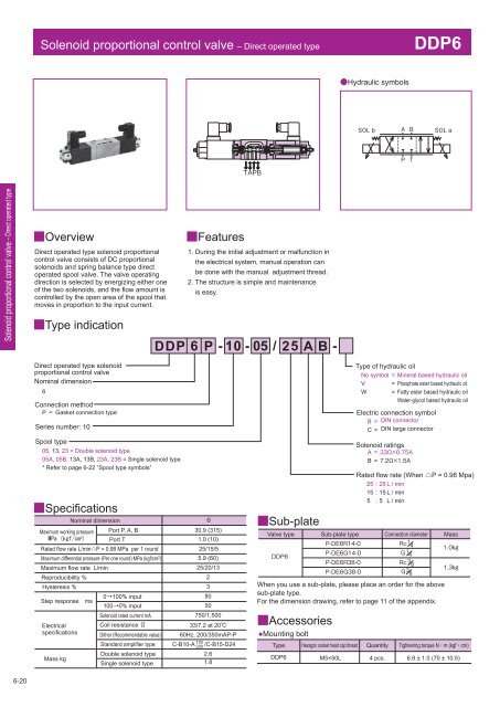
Solenoid proportional control valve – Direct operated type DDP6 Hydraulic symbols Solenoid proportional control valve – Direct operated type Overview Direct operated type solenoid proportional control valve consists of DC proportional solenoids and spring balance type direct operated spool valve. The valve operating direction is selected by energizing either one of the two solenoids, and the flow amount is controlled by the open area of the spool that moves in proportion to the input current. Type indication Features 1. During the initial adjustment or malfunction in the electrical system, manual operation can be done with the manual adjustment thread. 2. The structure is simple and maintenance is easy. Direct operated type solenoid proportional control valve Nominal dimension 6 Connection method P Gasket connection type Series number: 10 Spool type 05, 13, 23 = Double solenoid type 05A, 05B, 13A, 13B, 23A, 23B = Single solenoid type * Refer to page 6-22 “Spool type symbols” Specifications Nominal dimension Maximum working pressure Port P, A, B MPa (kgf/cm 2 ) Port T Rated flow rate L/minP = 0.98 MPa per 1 round Maximum differential pressure (Per one round) MPa (kgf/cm 2 ) Maximum flow rate L/min Reproducibility % Hysteresis % Step responsems Electrical specifications Mass kg 0100% input 1000% input Solenoid rated current mA Coil resistance Ω Dither (Recommendable value) Standard amplifier type Double solenoid type Single solenoid type 30.9 (315) 1.0 (10) 25/15/5 5.9 (60) 25/20/13 2 3 80 50 750/1,500 33/7.2 at 20 60Hz, 200/350mAP-P 100 C-B10-A 200 /C-B15-D24 2.6 1.8 Sub-plate Accessories ●Mounting bolt Type of hydraulic oil No symbol V W Solenoid ratings A = B = Rated flow rate (When P = 0.98 Mpa) 25 : 25 L / min 15 : 15 L / min 5 : 5 L / min Valve type Sub-plate type Connection diameter Mass When you use a sub-plate, please place an order for the above sub-plate type. For the dimension drawing, refer to page 11 of the appendix. Type Hexagon socket head cap thread Quantity Tightening torque N・m (kgf・cm) DDP6 M5×50L 4 pcs. 6.9 ± 1.0 (70 ± 10.5) = = = Mineral based hydraulic oil Phosphate ester based hydraulic oil Fatty ester based hydraulic oil Water-glycol based hydraulic oil Electric connection symbol B = DIN connector C = DIN large connector 6-20
- Page 222 and 223: Dimension drawing ZNS5-1 4-5.5 thro
- Page 224 and 225: ZNS10-1 4-6.6 through hole
- Page 226 and 227: Logic valve Logic valve KLD/LU A po
- Page 228 and 229: Logic valve Cover type symbols Nomi
- Page 230 and 231: Logic valve Pressure decreasing cha
- Page 232 and 233: Logic valve KLD - manifold Machinin
- Page 234 and 235: Logic valve 16 LU 25B
- Page 236 and 237: Logic valve LU 25 A 32DB Hydr
- Page 238 and 239: Logic valve LU40S Hydraulic symbo
- Page 240 and 241: Logic valve LU40E A B
- Page 242 and 243: Logic valve LU 50 63B O-ring “V
- Page 244 and 245: Logic valve 50 ●LU E 63 A L D E G
- Page 246 and 247: Logic valve LU80B Counterboring d
- Page 248 and 249: Logic valve LU 80 100 E A B
- Page 250 and 251: Selector valve Dimension drawing CS
- Page 252 and 253: Logic element for pressure control
- Page 254 and 255: Solenoid proportional control valve
- Page 256 and 257: ■Specifications Nominal dimension
- Page 258 and 259: Solenoid proportional balanced pist
- Page 260 and 261: Pressure override characteristics (
- Page 262 and 263: ●RBP35P-10/*-E B C P 165 130 X T
- Page 264 and 265: Current - Pressure characteristics
- Page 266 and 267: Solenoid proportional pilot pressur
- Page 268 and 269: ■Dimension drawing ●PRDP1M6-D 4
- Page 270 and 271: Specifications Nominal dimension
- Page 274 and 275: ■Current - Flow rate characterist
- Page 276 and 277: Specifications Maximum working pres
- Page 278 and 279: ●DHP22 (Single solenoid type) 94.
- Page 280 and 281: Specifications Nominal dimension 6
- Page 282 and 283: Solenoid proportional control valve
- Page 284 and 285: ■Dimension drawing ●DHPL16 18.3
- Page 286 and 287: Type indication C series Controller
- Page 288 and 289: For AC power supply double solenoid
- Page 290 and 291: For DC power supply double solenoid
- Page 292 and 293: For DC power supply double solenoid
- Page 294 and 295: Sub-plate Appendix-1
- Page 296 and 297: ●Pressure control valve ●Flow c
- Page 298 and 299: ●P-RB10 Counterboring diameter φ
- Page 300 and 301: ●P-CHY20 Screw diameter J, screw
- Page 302 and 303: ●P-DE10 115 11.5 92 32 46 23 75 2
- Page 304 and 305: P-DEH16 Counterborin
- Page 306 and 307: ●P-PU20 Counterboring diameterφC
- Page 308 and 309: FlangeNipple Appendix-15
- Page 310 and 311: ●STNL-High pressure 30.9 MPa (315
- Page 312 and 313: Application examples of SUN cartrid
- Page 314: Kawasaki Heavy Industries, Ltd. Ove
Solenoid proportional control valve – Direct operated type<br />
DDP6<br />
Hydraulic symbols<br />
<br />
<br />
<br />
<br />
<br />
<br />
<br />
Solenoid proportional control valve – Direct operated type<br />
Overview<br />
Direct operated type solenoid proportional<br />
control valve consists of DC proportional<br />
solenoids and spring balance type direct<br />
operated spool valve. The valve operating<br />
direction is selected by energizing either one<br />
of the two solenoids, and the flow amount is<br />
controlled by the open area of the spool that<br />
moves in proportion to the input current.<br />
Type indication<br />
Features<br />
1. During the initial adjustment or malfunction in<br />
the electrical system, manual operation can<br />
be done with the manual adjustment thread.<br />
2. The structure is simple and maintenance<br />
is easy.<br />
Direct operated type solenoid<br />
proportional control valve<br />
Nominal dimension<br />
6<br />
Connection method<br />
P Gasket connection type<br />
Series number: <strong>10</strong><br />
Spool type<br />
05, 13, 23 = Double solenoid type<br />
05A, 05B, 13A, 13B, 23A, 23B = Single solenoid type<br />
* Refer to page 6-22 “Spool type symbols”<br />
Specifications<br />
Nominal dimension<br />
Maximum working pressure Port P, A, B<br />
MPa (kgf/cm 2 ) Port T<br />
Rated flow rate L/minP = 0.98 MPa per 1 round<br />
Maximum differential pressure (Per one round) MPa (kgf/cm 2 )<br />
Maximum flow rate L/min<br />
Reproducibility %<br />
Hysteresis %<br />
Step responsems<br />
Electrical<br />
specifications<br />
Mass kg<br />
0<strong>10</strong>0% input<br />
<strong>10</strong>00% input<br />
Solenoid rated current mA<br />
Coil resistance Ω<br />
Dither (Recommendable value)<br />
Standard amplifier type<br />
Double solenoid type<br />
Single solenoid type<br />
<br />
30.9 (315)<br />
1.0 (<strong>10</strong>)<br />
25/15/5<br />
5.9 (60)<br />
25/20/13<br />
2<br />
3<br />
80<br />
50<br />
750/1,500<br />
33/7.2 at 20<br />
60Hz, 200/350mAP-P<br />
<strong>10</strong>0<br />
C-B<strong>10</strong>-A 200 /C-B15-D24<br />
2.6<br />
1.8<br />
Sub-plate<br />
Accessories<br />
●Mounting bolt<br />
Type of hydraulic oil<br />
No symbol<br />
V<br />
W<br />
Solenoid ratings<br />
A = <br />
B = <br />
Rated flow rate (When P = 0.98 Mpa)<br />
25 : 25 L / min<br />
15 : 15 L / min<br />
5 : 5 L / min<br />
Valve type Sub-plate type Connection diameter Mass<br />
<br />
<br />
<br />
<br />
<br />
<br />
<br />
<br />
<br />
<br />
<br />
When you use a sub-plate, please place an order for the above<br />
sub-plate type.<br />
For the dimension drawing, refer to page 11 of the appendix.<br />
Type Hexagon socket head cap thread Quantity Tightening torque N・m (kgf・cm)<br />
DDP6 M5×50L 4 pcs. 6.9 ± 1.0 (70 ± <strong>10</strong>.5)<br />
=<br />
=<br />
=<br />
Mineral based hydraulic oil<br />
Phosphate ester based hydraulic oil<br />
Fatty ester based hydraulic oil<br />
Water-glycol based hydraulic oil<br />
Electric connection symbol<br />
B = DIN connector<br />
C = DIN large connector<br />
6-20


