DH6/10
DH6/10 DH6/10
Solenoid operated directional valve Maximum flow rate When switching the valve to neutral state with spool type 06, 07 and 08 reaching the stroke end Number of positions Position holding method Spool type symbol Hydraulic symbols Solenoid Maximum flow rate L/min Working pressure MPa (kgf/cm 2 ) 10 (102) 16 (163) 25 (255) 31.5 (321) AC 26 21 18 16 06 a b DC, AC/DC conversion 35 24 21 20 3 positions 2 Spring center type 07 a b AC DC, AC/DC conversion 84 68 52 65 52 61 — — AC 100 100 100 100 08 a b DC, AC/DC conversion 120 120 120 120 1-16
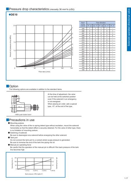
Pressure drop characteristics (viscosity 36 mm 2 /s (cSt)) DE10 Amount of pressure drop (MPa) 2.5 2.0 1.5 1.0 0.5 0 20 40 60 80 100 120 Flow rate (L/min) 1 2 3 4 5 6 7 8 9 Spool holding method 205 206 207 208 209 210 212 213 217 221 222 201 202 203 204 225 101 103 104 Flow direction P→A B→T P→B A→T P→T 7 7 7 7 − 9 7 7 9 1 6 5 6 5 1 9 9 9 9 5 9 7 7 7 − 7 8 7 8 − 7 7 7 8 − 9 7 9 7 − 7 7 7 7 − 7 8 7 7 − 7 7 7 7 − 6 − 5 − − 5 − 6 − − 3 2 9 9 − 2 1 7 7 − 7 7 2 1 − 6 − 6 − − 6 4 7 7 − 4 3 6 6 − Solenoid operated directional valve Option The following options are available in addition to the standard items. SOL. b At the time of adjustment, the valve can be held at the switched position even if the solenoid in an emergency is not energized. When placing an order, add a special type, -07, at the end of the type. Precautions in use Mounting posture When using the valve of the no spring detent type without excitation, mount the solenoid horizontally so that the detent effect is securely obtained. For the valve of other type, there is no limitation of mounting posture. Switching of solenoid Be sure to deenergize one solenoid before energizing the other solenoid. Tank port Do not connect the tank port to a conduit where surge pressure is generated. Be sure to immerse the end of the tank line piping into oil. Manual pin operating force Be careful that the operation of the manual pin is difficult if the back pressure of the tank line becomes high. Operating force N 150 100 50 0 15.3 10.2 5.1 1 (10.2) 2 (20.4) 3 (30.6) 4 (40.8) Back pressure MPa (kgf/cm 2 ) Operating force kgf 1-17
- Page 2 and 3: Oil Pressure Regulating Valve In ad
- Page 4 and 5: Safety Precautions Cautions concern
- Page 6 and 7: L LPR16 to 63 (Logic element for pr
- Page 8 and 9: Solenoid operated directional valve
- Page 10 and 11: Solenoid operated directional valve
- Page 12 and 13: Solenoid operated directional valve
- Page 14 and 15: Solenoid operated directional valve
- Page 16 and 17: Solenoid operated directional valve
- Page 18 and 19: Solenoid operated directional valve
- Page 20 and 21: Solenoid operated directional valve
- Page 24 and 25: Solenoid operated directional valve
- Page 26 and 27: Solenoid controlled pilot operated
- Page 28 and 29: Solenoid controlled pilot operated
- Page 30 and 31: Solenoid controlled pilot operated
- Page 32 and 33: Solenoid controlled pilot operated
- Page 34 and 35: Solenoid controlled pilot operated
- Page 36 and 37: Solenoid controlled pilot operated
- Page 38 and 39: Solenoid controlled pilot operated
- Page 40 and 41: Solenoid controlled pilot operated
- Page 42 and 43: Solenoid controlled pilot operated
- Page 44 and 45: Solenoid controlled pilot operated
- Page 46 and 47: Pilot operated directional valve (1
- Page 48 and 49: Pilot operated directional valve (1
- Page 50 and 51: Pilot operated directional valve (2
- Page 52 and 53: Pilot operated directional valve (2
- Page 54 and 55: Pilot operated directional valve (2
- Page 56 and 57: Pilot operated directional valve (3
- Page 58 and 59: Pilot operated directional valve (3
- Page 60 and 61: Pilot operated directional valve (3
- Page 62 and 63: Manual selector valve (1) Spool typ
- Page 64 and 65: Manual selector valve (1) ■Dimens
- Page 66 and 67: Manual selector valve (2) Spool typ
- Page 68 and 69: Manual selector valve (2) ■Dimens
- Page 70 and 71: Manual selector valve - KLA type Ma
Pressure drop characteristics (viscosity 36 mm 2 /s (cSt))<br />
DE<strong>10</strong><br />
Amount of pressure drop (MPa)<br />
2.5<br />
2.0<br />
1.5<br />
1.0<br />
0.5<br />
0<br />
20 40 60 80 <strong>10</strong>0 120<br />
Flow rate (L/min)<br />
1<br />
2<br />
3<br />
4<br />
5<br />
6<br />
7<br />
8<br />
9<br />
Spool<br />
holding<br />
method<br />
205<br />
206<br />
207<br />
208<br />
209<br />
2<strong>10</strong><br />
212<br />
213<br />
217<br />
221<br />
222<br />
201<br />
202<br />
203<br />
204<br />
225<br />
<strong>10</strong>1<br />
<strong>10</strong>3<br />
<strong>10</strong>4<br />
Flow direction<br />
P→A B→T P→B A→T P→T<br />
7 7 7 7 −<br />
9 7 7 9 1<br />
6 5 6 5 1<br />
9 9 9 9 5<br />
9 7 7 7 −<br />
7 8 7 8 −<br />
7 7 7 8 −<br />
9 7 9 7 −<br />
7 7 7 7 −<br />
7 8 7 7 −<br />
7 7 7 7 −<br />
6 − 5 − −<br />
5 − 6 − −<br />
3 2 9 9 −<br />
2 1 7 7 −<br />
7 7 2 1 −<br />
6 − 6 − −<br />
6 4 7 7 −<br />
4 3 6 6 −<br />
Solenoid operated directional valve<br />
Option<br />
The following options are available in addition to the standard items.<br />
SOL. b<br />
At the time of adjustment, the valve<br />
can be held at the switched position<br />
even if the solenoid in an emergency<br />
is not energized.<br />
When placing an order, add a special<br />
type, -07, at the end of the type.<br />
<br />
Precautions in use<br />
Mounting posture<br />
When using the valve of the no spring detent type without excitation, mount the solenoid<br />
horizontally so that the detent effect is securely obtained. For the valve of other type, there<br />
is no limitation of mounting posture.<br />
Switching of solenoid<br />
Be sure to deenergize one solenoid before energizing the other solenoid.<br />
Tank port<br />
Do not connect the tank port to a conduit where surge pressure is generated.<br />
Be sure to immerse the end of the tank line piping into oil.<br />
Manual pin operating force<br />
Be careful that the operation of the manual pin is difficult if the back pressure of the tank<br />
line becomes high.<br />
Operating force N<br />
150<br />
<strong>10</strong>0<br />
50<br />
0<br />
15.3<br />
<strong>10</strong>.2<br />
5.1<br />
1 (<strong>10</strong>.2) 2 (20.4) 3 (30.6) 4 (40.8)<br />
Back pressure MPa (kgf/cm 2 )<br />
Operating force kgf<br />
1-17


