DH6/10
DH6/10 DH6/10
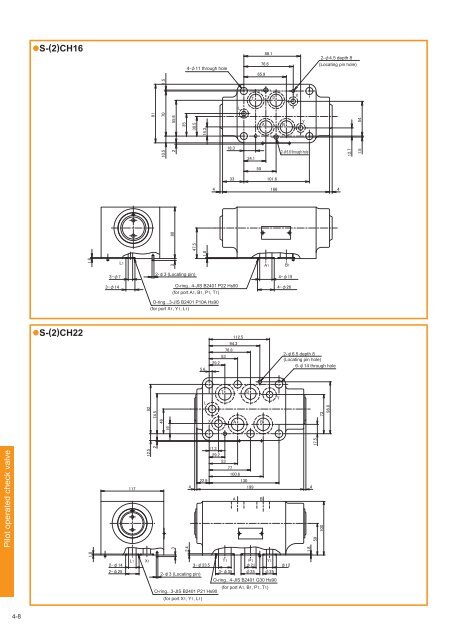
●S-(2)CH16 4-φ11 through hole 76.6 65.9 88.1 2-φ4.5 depth 8 (Locating pin hole) T P X L 91 10.5 70 55.6 35 1.5 2 30.5 14.3 18.3 34.1 A B Y 2-φ6.6 through hole 12.7 54 1.5 50 33 101.6 4 166 4 47.5 1.8 80 1.8 L1 3 A1 B1 3-φ7 2-φ3 (Locating pin) 4-φ19 3-φ14 O-ring...4-JIS B2401 P22 Hs90 (for port A1, B1, P1, T1) 4-φ26 O-ring...3-JIS B2401 P10A Hs90 (for port X1, Y1, L1) ●S-(2)CH22 5.6 112.5 94.3 76.8 53 29.2 2-φ6.5 depth 8 (Locating pin hole) 6-φ14 through hole 92 74.5 46 T P L X A B Y 73 96.8 Pilot operated check valve A B 1.8 19 117 12.5 2 4 22.9 17.3 29.2 53 77 100.6 130 199 4 3 2.4 1.8 17.5 59 100 2-φ14 2-φ25 L1 X1 2-φ3 (Locating pin) 3-φ23.5 O-ring...3-JIS B2401 P21 Hs90 (for port X1, Y1, L1) T1 3-φ35 P1 φ21 φ35 Y1 φ25 O-ring...4-JIS B2401 G30 Hs90 (for port A1, B1, P1, T1) φ12 4-8
Relief valve S-(2)RB Type indication Sandwich type Relief valve RB Single type 2RB Double type Nominal dimension 6, 10 Series number: 10 Relief valve incorporated port symbol Symbol Incorporated port Flow direction of relief Port Port Port Port Port Port Port Type of hydraulic oil No symbol Mineral based hydraulic oil V Phosphate ester based hydraulic oil W Fatty ester based hydraulic oil Water-glycol based hydraulic oil Highest adjustment pressure 100 = 9.8MPa100kgf/cm 2 315 = 30.9MPa315kgf/cm 2 Shape of adjustment part 4 = Thread adjustment (without cap) The relief valve - balance piston and cartridge type (refer to the section of the type number index of “RB1M6, 10”) is used for the relief valve. Hydraulic symbols Relief valve (Note) P1, A1, B1 and T1 show ports on the sub-plate side while P, A, B and T show ports on the selector valve side. 4-9
- Page 140 and 141: Secondary side minimum adjustment p
- Page 142 and 143: The direct operated type relief val
- Page 144 and 145: ●B*G/GT*・3 ●Handle adjusting
- Page 146 and 147: ●B*P*・1 ●Handle adjusting typ
- Page 148 and 149: Counterbalance valve CBD Overview
- Page 150 and 151: Dimension drawing CBD*G/R Handle ad
- Page 152 and 153: Pressure drop characteristics (visc
- Page 154 and 155: Variable throttle valve T1M 3-2 Th
- Page 156 and 157: ■Dimension drawing ●T1M*P C (wh
- Page 158 and 159: ■Pressure - Flow rate characteris
- Page 160 and 161: ■Dimension drawing ●T1M*P L1 L2
- Page 162 and 163: ■Pressure - Flow rate characteris
- Page 164 and 165: ■Pressure drop characteristics (v
- Page 166 and 167: 3-13 ■Dimension drawing ●TC1M*P
- Page 168 and 169: Pressure - Flow rate characteristic
- Page 170 and 171: ■Pressure drop characteristics (v
- Page 172 and 173: Pressure - Flow rate characteristic
- Page 174 and 175: 8 ●F*G/R 4-φ5.5 through hole Cou
- Page 176 and 177: Specifications Nominal dimension Ma
- Page 178 and 179: Temperature and pressure compensate
- Page 180 and 181: Three-way flow regulating valve
- Page 182 and 183: ■Dimension drawing ●FK10 6 10 9
- Page 184 and 185: Check valve S-(2)C Type indicat
- Page 186 and 187: ■Dimension drawing ●S-(2)C6 2 T
- Page 188 and 189: Specifications Nominal dimension Ma
- Page 192 and 193: Relief valve Specifications Nominal
- Page 194 and 195: Sequence valve - Direct operated ty
- Page 196 and 197: ■Dimension drawing ●S-SD6-10-P
- Page 198 and 199: Pressure reducing valve - Direct op
- Page 200 and 201: ■Dimension drawing ●S-PRD6-10-P
- Page 202 and 203: Throttle valve S-(2)T Type
- Page 204 and 205: ■Dimension drawing ●S-T6-10-P 4
- Page 206 and 207: ●S-T10-10-P 46 39.7 16 4-φ6.6 th
- Page 208 and 209: Slow return check valve S-(2)TC
- Page 210 and 211: Opening - Flow rate characteristics
- Page 212 and 213: Dimension drawing S-2TC6 Maximum 21
- Page 214 and 215: ●S-(2)TC22 5.6 29.2 100.6 94.3 76
- Page 216 and 217: ■Dimension drawing ●S-4C5 60 48
- Page 218 and 219: Check valve block ZA Hydraulic
- Page 220 and 221: ●ZA30 5 208.5 116 2 82.5 51.3 50.
- Page 222 and 223: Dimension drawing ZNS5-1 4-5.5 thro
- Page 224 and 225: ZNS10-1 4-6.6 through hole
- Page 226 and 227: Logic valve Logic valve KLD/LU A po
- Page 228 and 229: Logic valve Cover type symbols Nomi
- Page 230 and 231: Logic valve Pressure decreasing cha
- Page 232 and 233: Logic valve KLD - manifold Machinin
- Page 234 and 235: Logic valve 16 LU 25B
- Page 236 and 237: Logic valve LU 25 A 32DB Hydr
- Page 238 and 239: Logic valve LU40S Hydraulic symbo
●S-(2)CH16<br />
4-φ11 through hole<br />
76.6<br />
65.9<br />
88.1<br />
2-φ4.5 depth 8<br />
(Locating pin hole)<br />
T<br />
P<br />
X<br />
L<br />
91<br />
<strong>10</strong>.5 70<br />
55.6<br />
35<br />
1.5<br />
2<br />
30.5<br />
14.3<br />
18.3<br />
34.1<br />
A<br />
B<br />
Y<br />
2-φ6.6 through hole<br />
12.7<br />
54<br />
1.5<br />
50<br />
33<br />
<strong>10</strong>1.6<br />
4 166<br />
4<br />
47.5<br />
1.8<br />
80<br />
1.8<br />
L1<br />
3<br />
A1<br />
B1<br />
3-φ7<br />
2-φ3 (Locating pin)<br />
4-φ19<br />
3-φ14<br />
O-ring...4-JIS B2401 P22 Hs90<br />
(for port A1, B1, P1, T1)<br />
4-φ26<br />
O-ring...3-JIS B2401 P<strong>10</strong>A Hs90<br />
(for port X1, Y1, L1)<br />
●S-(2)CH22<br />
5.6<br />
112.5<br />
94.3<br />
76.8<br />
53<br />
29.2<br />
2-φ6.5 depth 8<br />
(Locating pin hole)<br />
6-φ14 through hole<br />
92<br />
74.5<br />
46<br />
T P<br />
L<br />
X A B<br />
Y<br />
73<br />
96.8<br />
Pilot operated check valve<br />
A<br />
B<br />
1.8<br />
19<br />
117<br />
12.5<br />
2<br />
4<br />
22.9<br />
17.3<br />
29.2<br />
53<br />
77<br />
<strong>10</strong>0.6<br />
130<br />
199<br />
4<br />
3<br />
2.4<br />
1.8<br />
17.5<br />
59<br />
<strong>10</strong>0<br />
2-φ14<br />
2-φ25<br />
L1<br />
X1<br />
2-φ3 (Locating pin)<br />
3-φ23.5<br />
O-ring...3-JIS B2401 P21 Hs90<br />
(for port X1, Y1, L1)<br />
T1<br />
3-φ35<br />
P1<br />
φ21<br />
φ35<br />
Y1<br />
φ25<br />
O-ring...4-JIS B2401 G30 Hs90<br />
(for port A1, B1, P1, T1)<br />
φ12<br />
4-8


