DH6/10
DH6/10 DH6/10
Secondary side minimum adjustment pressure characteristics (viscosity 36 mm 2 /s (cSt)) Pressure increase value per turn (clockwise) of adjust thread MPa (kgf/cm 2 ) Nominal Highest dimension adjustment pressure 10, 20, 30 (Note) As the above value is a calculated value, there are slight variations in the product. Sub-plate Valve type Sub-plate type Dimension drawing PRB Connection diameter Mass Accessories Mounting bolt Type Hexagon socket head cap thread Quantity Tightening torque Nm (kgfcm) When you use a sub-plate, please place an order for the above sub-plate type. For the dimension drawing, refer to page 6, 7 of the appendix. Pressure reducing valve – Balanced piston type pilot operated Maximum 187 Maximum 187 13 Counterboring depth 1.4 D2 Counterboring depth H6 O-ring“W” (for port A, B) Width across flat 19 Width across flat 30 ●Thread adjusting type O-ring2-JIS B2401 P10 Hs90 (for port X, Y) 6 (Locating pin) ●Handle adjusting type Width across flat30 ●Handle with key adjusting type Note: Port X is not used. Nominal dimension O-ring dimension “W” 2-53
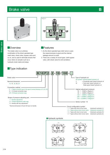
* Brake valve Overview This brake valve is an arbitrary combination of the direct operated type relief valve, check valve, bypass valve and so on, and is used to eliminate shocks that occur when an actuator such as a hydraulic motor starts and stops. Features 1. As the direct operated type relief valve is used, the responsiveness is good and the internal leakage amount is small. 2. There are a variety of circuit types. (with bypass valve, with check valve for anti-cavitation) Type indication Brake valve Nominal dimension 10, 15, 20, 25, 30 Connection method P = Gasket connection type (in the case of nominal dimension of 10, 20, 30) G = G thread connection type GT= R thread connection type Shape of pressure adjusting part Handle adjustment Thread adjustment (with cap) Handle with key adjustment* *Nominal dimension 25 and 30 have no handle. Type of hydraulic oil No symbol = Mineral based hydraulic oil V = Phosphate ester based hydraulic oil W = Fatty ester based hydraulic oil Water-glycol based hydraulic oil Highest adjustment pressure 25 50 100 200 315 = = = = = 2.5MPa 25kgf/cm 2 4.9MPa 50kgf/cm 2 9.8MPa 100kgf/cm 2 19.6MPa 200kgf/cm 2 30.9MPa 315kgf/cm 2 Series number: 10 Circuit configuration symbol 1 = Types with short circuit valve (Hydraulic symbols) (1) 2 = Types without short circuit valve (Hydraulic symbols) (2) 3 = Types with short circuit valve (Hydraulic symbols) (3) 4 = Types without short circuit valve (Hydraulic symbols) (4) Hydraulic symbols 2-54
- Page 90 and 91: Hydraulic symbols Pressure increase
- Page 92 and 93: Pressure override characteristics (
- Page 94 and 95: Dimension drawing RD*G/R RDV6G/R L2
- Page 96 and 97: RDV1M6R A 62 Maximum of 152 61 14.5
- Page 98 and 99: Type indication RBE Relief valve -
- Page 100 and 101: Pilot valve The type indication of
- Page 102 and 103: Dimension drawing RB*P B1 B2 X P T
- Page 104 and 105: Relief valve - Balanced piston type
- Page 106 and 107: Type indication RB35X Pilot relief
- Page 108 and 109: RB35F 38 19 110 Y port G1/4 screw d
- Page 110 and 111: Type indication RB52 Relief valve-
- Page 112 and 113: Pilot valve The type indication of
- Page 114 and 115: Three stage pressure relief valve 3
- Page 116 and 117: Dimension drawing 3RBE L10 L1 L8 L3
- Page 118 and 119: Pressure override characteristics (
- Page 120 and 121: PUE Pilot operated unloading relief
- Page 122 and 123: Dimension drawing PU10 47.1 85 66.7
- Page 124 and 125: Pilot operated unloading relief val
- Page 126 and 127: Dimension drawing PU35P (Gasket con
- Page 128 and 129: Specifications SD6P SD10P P-DE6R14-
- Page 130 and 131: Sequence valve — Balanced piston
- Page 132 and 133: Minimum adjustment pressure charac
- Page 134 and 135: Dimension drawing SB L5 L3 L2 6 13
- Page 136 and 137: Pressure override characteristics (
- Page 138 and 139: Pressure reducing valve - Balanced
- Page 142 and 143: The direct operated type relief val
- Page 144 and 145: ●B*G/GT*・3 ●Handle adjusting
- Page 146 and 147: ●B*P*・1 ●Handle adjusting typ
- Page 148 and 149: Counterbalance valve CBD Overview
- Page 150 and 151: Dimension drawing CBD*G/R Handle ad
- Page 152 and 153: Pressure drop characteristics (visc
- Page 154 and 155: Variable throttle valve T1M 3-2 Th
- Page 156 and 157: ■Dimension drawing ●T1M*P C (wh
- Page 158 and 159: ■Pressure - Flow rate characteris
- Page 160 and 161: ■Dimension drawing ●T1M*P L1 L2
- Page 162 and 163: ■Pressure - Flow rate characteris
- Page 164 and 165: ■Pressure drop characteristics (v
- Page 166 and 167: 3-13 ■Dimension drawing ●TC1M*P
- Page 168 and 169: Pressure - Flow rate characteristic
- Page 170 and 171: ■Pressure drop characteristics (v
- Page 172 and 173: Pressure - Flow rate characteristic
- Page 174 and 175: 8 ●F*G/R 4-φ5.5 through hole Cou
- Page 176 and 177: Specifications Nominal dimension Ma
- Page 178 and 179: Temperature and pressure compensate
- Page 180 and 181: Three-way flow regulating valve
- Page 182 and 183: ■Dimension drawing ●FK10 6 10 9
- Page 184 and 185: Check valve S-(2)C Type indicat
- Page 186 and 187: ■Dimension drawing ●S-(2)C6 2 T
- Page 188 and 189: Specifications Nominal dimension Ma
* <br />
<br />
<br />
<br />
Brake valve<br />
Overview<br />
This brake valve is an arbitrary<br />
combination of the direct operated type<br />
relief valve, check valve, bypass valve and<br />
so on, and is used to eliminate shocks that<br />
occur when an actuator such as a<br />
hydraulic motor starts and stops.<br />
Features<br />
1. As the direct operated type relief valve is used,<br />
the responsiveness is good and the internal<br />
leakage amount is small.<br />
2. There are a variety of circuit types. (with bypass<br />
valve, with check valve for anti-cavitation)<br />
Type indication<br />
Brake valve<br />
Nominal dimension<br />
<strong>10</strong>, 15, 20, 25, 30<br />
Connection method<br />
P = Gasket connection type (in the case of nominal dimension of <strong>10</strong>, 20, 30)<br />
G = G thread connection type<br />
GT=<br />
R thread connection type<br />
Shape of pressure adjusting part<br />
Handle adjustment<br />
Thread adjustment (with cap)<br />
Handle with key adjustment*<br />
*Nominal dimension 25 and 30 have no handle.<br />
Type of hydraulic oil<br />
No symbol = Mineral based hydraulic oil<br />
V = Phosphate ester based hydraulic oil<br />
W = Fatty ester based hydraulic oil<br />
Water-glycol based hydraulic oil<br />
Highest adjustment pressure<br />
25<br />
50<br />
<strong>10</strong>0<br />
200<br />
315<br />
=<br />
=<br />
=<br />
=<br />
=<br />
2.5MPa 25kgf/cm 2 <br />
4.9MPa 50kgf/cm 2 <br />
9.8MPa <strong>10</strong>0kgf/cm 2 <br />
19.6MPa 200kgf/cm 2 <br />
30.9MPa 315kgf/cm 2 <br />
Series number: <strong>10</strong><br />
Circuit configuration symbol<br />
1 = Types with short circuit valve (Hydraulic symbols) (1)<br />
2 = Types without short circuit valve (Hydraulic symbols) (2)<br />
3 = Types with short circuit valve (Hydraulic symbols) (3)<br />
4 = Types without short circuit valve (Hydraulic symbols) (4)<br />
Hydraulic symbols<br />
<br />
<br />
<br />
<br />
<br />
<br />
<br />
<br />
<br />
<br />
<br />
<br />
<br />
<br />
2-54


