DH6/10
DH6/10 DH6/10
Dimension drawing PU35P (Gasket connection type) 165 130 X 21.5 149 100 21 PU35F (Flange connection type) 110 58 71.5 18 129.5 G 1 4 Screw depth 12 Maximum 213 178 45 45 98 40 PCD 130 4-M16 Screw depth 22 70 O-ring JIS B2401 P14 Hs90 (for port X) 35 70 20 115 37.5 140 3.5 195 Handle adjusting type Screw adjusting type Handle with key adjusting type Maximum 213 190 Maximum 213 30 60 35 60 Width across flat 19 Width across flat 30 Width across flat 30 40 O-ring 2-JIS B2401 G50 Hs90 5.2 40 55 (for port P, T) 18 55 6-M16 Pilot operated unloading relief valve (2) Handle adjusting type Screw adjusting type Handle with key adjusting type 190 Maximum 213 30 21 X 60 35 60 Width across flat 19 Width across flat 30 Width across flat 30 45 45 4098 PCD 4-M16 Screw depth 22 2-39
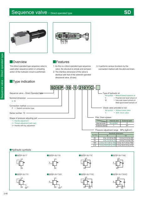
Sequence valve Direct operated type SD X B A Y Sequence valve – Direct operated type Overview This direct operated type sequence valve is used when sequence action or unloading action of the hydraulic circuit is performed. Type indication Sequence valve – Direct Operated type Nominal dimension 6, 10 Features 1. As this is a direct operated type sequence valve, the structure is simple and compact. 2. The interface dimension of the valve is identical with that of the solenoid operated directional valve. (6 size) 3. It performs various functions by the connection method with the pilot and drain. Type of hydraulic oil No symbol = Mineral based hydraulic oil V = Phosphate ester based hydraulic oil W = Fatty ester based hydraulic oil Water-glycol based hydraulic oil Connection method P = Gasket connection type Series number: 10 Check valve provided or not No symbol = Without check valve C = Shape of pressure adjusting part 1 = Handle adjustment 2 = Thread adjustment (with cap) 3 = Handle with key adjustment Pilot, Drain system Internal drain External drain Internal pilot No symbol Y External pilot X XY Pressure adjustment rangeMPa (kgf/cm 2 ) Symbol 25 75 150 210 Nominal dimension 6 10 0 to 2.5 (0 to 25) 0.2 to 2.5 (2 to 25) 0 to 7.4 (0 to 75) 0.4 to 7.4 (4 to 75) 2.9 to 14.7 (30 to 150) 1.0 to 14.7 (10 to 150) 3.4 to 20.6 (35 to 210) 1.0 to 20.6 (10 to 210) Hydraulic symbols 6 6 6 6 SD 10P-10-*/* SD 10P-10-*/*X SD 10P-10-*/*C SD 10P-10-*/*XC A X A A X A B B B B 6 SD 10P-10-*/*Y SD 10P-10-*/*XY SD 10P-10-*/*YC SD 10P-10-*/*XYC A X 6 A 6 A X 6 A B Y B Y B Y B Y 2-40
- Page 76 and 77: Amount of pressure drop (MPa Check
- Page 78 and 79: 45° Check valve (2) ●C (flange c
- Page 80 and 81: Pilot operated check valve (1) Sub-
- Page 82 and 83: A Y B X Pilot operated check valve
- Page 84 and 85: Pilot operated check valve (2) Flan
- Page 86 and 87: Pressure gauge valve Pressure gauge
- Page 88 and 89: Page Relief valve - Direct operated
- Page 90 and 91: Hydraulic symbols Pressure increase
- Page 92 and 93: Pressure override characteristics (
- Page 94 and 95: Dimension drawing RD*G/R RDV6G/R L2
- Page 96 and 97: RDV1M6R A 62 Maximum of 152 61 14.5
- Page 98 and 99: Type indication RBE Relief valve -
- Page 100 and 101: Pilot valve The type indication of
- Page 102 and 103: Dimension drawing RB*P B1 B2 X P T
- Page 104 and 105: Relief valve - Balanced piston type
- Page 106 and 107: Type indication RB35X Pilot relief
- Page 108 and 109: RB35F 38 19 110 Y port G1/4 screw d
- Page 110 and 111: Type indication RB52 Relief valve-
- Page 112 and 113: Pilot valve The type indication of
- Page 114 and 115: Three stage pressure relief valve 3
- Page 116 and 117: Dimension drawing 3RBE L10 L1 L8 L3
- Page 118 and 119: Pressure override characteristics (
- Page 120 and 121: PUE Pilot operated unloading relief
- Page 122 and 123: Dimension drawing PU10 47.1 85 66.7
- Page 124 and 125: Pilot operated unloading relief val
- Page 128 and 129: Specifications SD6P SD10P P-DE6R14-
- Page 130 and 131: Sequence valve — Balanced piston
- Page 132 and 133: Minimum adjustment pressure charac
- Page 134 and 135: Dimension drawing SB L5 L3 L2 6 13
- Page 136 and 137: Pressure override characteristics (
- Page 138 and 139: Pressure reducing valve - Balanced
- Page 140 and 141: Secondary side minimum adjustment p
- Page 142 and 143: The direct operated type relief val
- Page 144 and 145: ●B*G/GT*・3 ●Handle adjusting
- Page 146 and 147: ●B*P*・1 ●Handle adjusting typ
- Page 148 and 149: Counterbalance valve CBD Overview
- Page 150 and 151: Dimension drawing CBD*G/R Handle ad
- Page 152 and 153: Pressure drop characteristics (visc
- Page 154 and 155: Variable throttle valve T1M 3-2 Th
- Page 156 and 157: ■Dimension drawing ●T1M*P C (wh
- Page 158 and 159: ■Pressure - Flow rate characteris
- Page 160 and 161: ■Dimension drawing ●T1M*P L1 L2
- Page 162 and 163: ■Pressure - Flow rate characteris
- Page 164 and 165: ■Pressure drop characteristics (v
- Page 166 and 167: 3-13 ■Dimension drawing ●TC1M*P
- Page 168 and 169: Pressure - Flow rate characteristic
- Page 170 and 171: ■Pressure drop characteristics (v
- Page 172 and 173: Pressure - Flow rate characteristic
- Page 174 and 175: 8 ●F*G/R 4-φ5.5 through hole Cou
Sequence valve Direct operated type<br />
SD<br />
X B A Y<br />
Sequence valve – Direct operated type<br />
Overview<br />
This direct operated type sequence valve is<br />
used when sequence action or unloading<br />
action of the hydraulic circuit is performed.<br />
Type indication<br />
Sequence valve – Direct Operated type<br />
Nominal dimension<br />
6, <strong>10</strong><br />
Features<br />
1. As this is a direct operated type sequence<br />
valve, the structure is simple and compact.<br />
2. The interface dimension of the valve is<br />
identical with that of the solenoid operated<br />
directional valve. (6 size)<br />
3. It performs various functions by the<br />
connection method with the pilot and drain.<br />
Type of hydraulic oil<br />
No symbol = Mineral based hydraulic oil<br />
V = Phosphate ester based hydraulic oil<br />
W = Fatty ester based hydraulic oil<br />
Water-glycol based hydraulic oil<br />
Connection method<br />
P = Gasket connection type<br />
Series number: <strong>10</strong><br />
Check valve provided or not<br />
No symbol = Without check valve<br />
C = <br />
Shape of pressure adjusting part<br />
1 = Handle adjustment<br />
2 = Thread adjustment (with cap)<br />
3 = Handle with key adjustment<br />
Pilot, Drain system<br />
Internal drain<br />
External drain<br />
Internal pilot<br />
No symbol<br />
Y<br />
External pilot<br />
X<br />
XY<br />
Pressure adjustment rangeMPa (kgf/cm 2 )<br />
Symbol<br />
25<br />
75<br />
150<br />
2<strong>10</strong><br />
Nominal dimension<br />
6 <strong>10</strong><br />
0 to 2.5 (0 to 25) 0.2 to 2.5 (2 to 25)<br />
0 to 7.4 (0 to 75) 0.4 to 7.4 (4 to 75)<br />
2.9 to 14.7 (30 to 150) 1.0 to 14.7 (<strong>10</strong> to 150)<br />
3.4 to 20.6 (35 to 2<strong>10</strong>) 1.0 to 20.6 (<strong>10</strong> to 2<strong>10</strong>)<br />
Hydraulic symbols<br />
6<br />
6<br />
6<br />
6<br />
SD <strong>10</strong>P-<strong>10</strong>-*/*<br />
SD <strong>10</strong>P-<strong>10</strong>-*/*X<br />
SD <strong>10</strong>P-<strong>10</strong>-*/*C<br />
SD <strong>10</strong>P-<strong>10</strong>-*/*XC<br />
A<br />
X<br />
A<br />
A<br />
X<br />
A<br />
B<br />
B<br />
B<br />
B<br />
6<br />
SD <strong>10</strong>P-<strong>10</strong>-*/*Y<br />
SD <strong>10</strong>P-<strong>10</strong>-*/*XY<br />
SD <strong>10</strong>P-<strong>10</strong>-*/*YC<br />
SD <strong>10</strong>P-<strong>10</strong>-*/*XYC<br />
A<br />
X<br />
6<br />
A<br />
6<br />
A<br />
X<br />
6<br />
A<br />
B<br />
Y<br />
B<br />
Y<br />
B<br />
Y<br />
B<br />
Y<br />
2-40


