DH6/10
DH6/10 DH6/10
Dimension drawing RB*P B1 B2 X P T L8 L2 L1 L3 L4 G1/4 With Y port only for (external drain type) L6 Maximum L7 Maximum L7 30 L5 Nominal dimension 10 20 30 B1 78 100 115 100 H2 78 O-ringJIS B2401 P10 Hs90 (for port X) 1.4 B2 54 69.8 82.5 M5 13 D1 4-M12 4-M16 4-M18 X D2 12 25 31 4-D1 P T 6 (Locating pin) L9 D2 D3 4 Screw adjusting type D3 20 35 40 (Y) L1 23.5 34 41.5 L2 22.2 11.1 12.7 H1 L3 47.6 55.5 76.2 26 35 L4 54 66.7 89 L5 99.5 113 123 L6 156.5 168 179 Handle adjusting type L7 179 193 203 L8 0 23.8 31.7 60 Width across flat 30 Width across flat 30 Width across flat 19 O-ring “S” (for port P, T) L9 22.1 33.3 44.4 H1 1.8 2.4 2.4 Handle with key adjusting type H2 19 24 24 60 O-ring dimension “S” 2-JIS B2401 P16 Hs90 2-JIS B2401 G30 Hs90 2-JIS B2401 G35 Hs90 Relief valve – Balanced piston type pilot operated (1) RB 10 30 C 61 4.2 Machining dimension of manifold 6 59 32 ±0.2 44 32 44 ±0.2 P T 25 6 M5 screw depth 6 Through hole of pilot hole 40 2 11 20 42 4-M8 2-O-ring 2.427.3(Hs90) Backup ring 3228.40.8 17 51 32 90 164 Maximum 187 6 (Y) 13 G1/4 Screw adjusting type RB*C-10-*/*Y With Y port only for (external drain type) 35 O-ring 2-JIS B2401 P10 Hs90 (for port P, T) 17 2x45° Nozzle M4 D=1 28.4 +0.1 0 2x45° 12.5 35 51 ±0.2 61 32H7 3.2 1.6 C0.1 25 D2 3.2 P R0.4 24 D1 2x30° 4-M8-12/16 D3 25.5 34 38 0.1 0 (finish range) T 1.6 3.2 1.6 40 +0.1 0 42 +0.1 +0.05 22 up to drill shoulder for RB30C Through hole of RB10 to D2 48 Maximum 187 30 Width across flat 30 Width across flat 30 60 60 Nominal dimension 10 D1 10 D2 40 D3 10 A Through hole to D2 Width across flat 19 Handle adjusting type Handle with key adjusting type 30 32 45 32 22 2-15
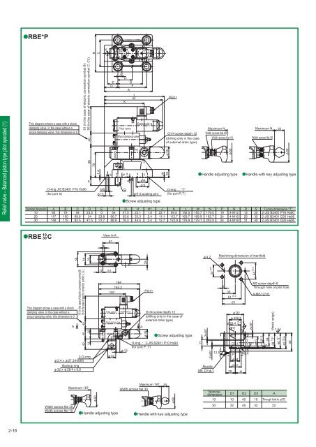
RBE*P B C X P T Relief valve – Balanced piston type pilot operated (1) This diagram shows a case with a shock damping valve. In the case without a shock damping valve, this dimension is 0. Nominal dimension 10 20 30 A 90 117 148 B 78 100 115 C 54 69.8 82.5 91 (in the case of electric connection symbol B) 95 (in the case of electric connection symbol C, CL) O-ring JIS B2401 P10 Hs90 (for port X) 98 40 P 78 D 23.5 34 41.5 1.4 M5 13 E 0 23.8 31.7 E D X F 54 66.7 88.9 J H G F A L M K Pilot valve Shock damping valve P Q 4 Screw adjusting type G 47.5 55.6 76.2 (Y) Solenoid a (Locating pin) H 22.1 33.3 44.4 T R S H1 1.8 2.4 2.4 H1 26 J 22.1 11.1 12.7 PG11 G1/4 screw depth 12 (drilling only in the case of external drain type) 35 O-ring … “T” (for port P,T) K 99.5 112.7 122.9 L 156.5 169.7 179.9 M 155.7 168.9 179.1 Maximum N Width across flat 30 Width across flat 19 Handle adjusting type N 179.5 192.7 202.9 P 19 24 24 60 Q 4-M12 4-M16 4-M18 Handle with key adjusting type R 12 25 31 Maximum N Width across flat 30 S 20 35 40 30 60 O-ring dimension “T” 2-JIS B2401 P16 Hs90 2-JIS B2401 G30 Hs90 2-JIS B2401 G35 Hs90 RBE 10 30 C View A-A 6 61 59 44 32 P T 25 4.2 Machining dimension of manifold This diagram shows a case with a shock damping valve. In the case without a shock damping valve, this dimension is 0. A 91 (in the case of electric connection symbol B) 95 (in the case of electric connection symbol C, CL) 40 40 20 42 11 2-O-ring 2.427.3(Hs90) Backup ring 3228.40.8 17 51 164 163.2 107 Pilot valve Shock damping valve 32 Solenoid a (Y) 6 13 A PG11 G1/4 screw depth 12 (drilling only in the case of external drain type) 35 Screw adjusting type O-ring 2-JIS B2401 P10 Hs90 (for port P, T) 32 ±0.2 17 2x45° 2x45° Nozzle M4 D=1 12.5 6 35 51 ±0.2 25 61 D2 32H7 28.4 +0.2 0 3.2 1.6 C0.1 3.2 P R0.4 24 D1 A 2x30° 44 ±0.2 M5 screw depth 6 Through hole of pilot hole 4-M8-12/16 T 1.6 3.2 φD3 25.5 34 (finish range) 38 0.1 1.6 40 +0.1 0 42 +0.1 +0.05 48 Maximum 187 30 Maximum 187 Width across flat 30 60 60 Width across flat 30 Width across flat 19 Handle adjusting type Handle with key adjusting type Nominal dimension 10 30 D1 10 32 D2 40 45 D3 10 32 A Through hole to D2 22 2-16
- Page 52 and 53: Pilot operated directional valve (2
- Page 54 and 55: Pilot operated directional valve (2
- Page 56 and 57: Pilot operated directional valve (3
- Page 58 and 59: Pilot operated directional valve (3
- Page 60 and 61: Pilot operated directional valve (3
- Page 62 and 63: Manual selector valve (1) Spool typ
- Page 64 and 65: Manual selector valve (1) ■Dimens
- Page 66 and 67: Manual selector valve (2) Spool typ
- Page 68 and 69: Manual selector valve (2) ■Dimens
- Page 70 and 71: Manual selector valve - KLA type Ma
- Page 72 and 73: Check valve (1) ■Specifications N
- Page 74 and 75: Check valve (1) ●C (cartridge typ
- Page 76 and 77: Amount of pressure drop (MPa Check
- Page 78 and 79: 45° Check valve (2) ●C (flange c
- Page 80 and 81: Pilot operated check valve (1) Sub-
- Page 82 and 83: A Y B X Pilot operated check valve
- Page 84 and 85: Pilot operated check valve (2) Flan
- Page 86 and 87: Pressure gauge valve Pressure gauge
- Page 88 and 89: Page Relief valve - Direct operated
- Page 90 and 91: Hydraulic symbols Pressure increase
- Page 92 and 93: Pressure override characteristics (
- Page 94 and 95: Dimension drawing RD*G/R RDV6G/R L2
- Page 96 and 97: RDV1M6R A 62 Maximum of 152 61 14.5
- Page 98 and 99: Type indication RBE Relief valve -
- Page 100 and 101: Pilot valve The type indication of
- Page 104 and 105: Relief valve - Balanced piston type
- Page 106 and 107: Type indication RB35X Pilot relief
- Page 108 and 109: RB35F 38 19 110 Y port G1/4 screw d
- Page 110 and 111: Type indication RB52 Relief valve-
- Page 112 and 113: Pilot valve The type indication of
- Page 114 and 115: Three stage pressure relief valve 3
- Page 116 and 117: Dimension drawing 3RBE L10 L1 L8 L3
- Page 118 and 119: Pressure override characteristics (
- Page 120 and 121: PUE Pilot operated unloading relief
- Page 122 and 123: Dimension drawing PU10 47.1 85 66.7
- Page 124 and 125: Pilot operated unloading relief val
- Page 126 and 127: Dimension drawing PU35P (Gasket con
- Page 128 and 129: Specifications SD6P SD10P P-DE6R14-
- Page 130 and 131: Sequence valve — Balanced piston
- Page 132 and 133: Minimum adjustment pressure charac
- Page 134 and 135: Dimension drawing SB L5 L3 L2 6 13
- Page 136 and 137: Pressure override characteristics (
- Page 138 and 139: Pressure reducing valve - Balanced
- Page 140 and 141: Secondary side minimum adjustment p
- Page 142 and 143: The direct operated type relief val
- Page 144 and 145: ●B*G/GT*・3 ●Handle adjusting
- Page 146 and 147: ●B*P*・1 ●Handle adjusting typ
- Page 148 and 149: Counterbalance valve CBD Overview
- Page 150 and 151: Dimension drawing CBD*G/R Handle ad
RBE*P<br />
B<br />
C<br />
X<br />
P<br />
T<br />
Relief valve – Balanced piston type pilot operated (1)<br />
This diagram shows a case with a shock<br />
damping valve. In the case without a<br />
shock damping valve, this dimension is 0.<br />
Nominal dimension<br />
<strong>10</strong><br />
20<br />
30<br />
A<br />
90<br />
117<br />
148<br />
B<br />
78<br />
<strong>10</strong>0<br />
115<br />
C<br />
54<br />
69.8<br />
82.5<br />
91 (in the case of electric connection symbol B)<br />
95 (in the case of electric connection symbol C, CL)<br />
O-ring JIS B2401 P<strong>10</strong> Hs90<br />
(for port X)<br />
98 40<br />
P<br />
78<br />
D<br />
23.5<br />
34<br />
41.5<br />
1.4<br />
M5<br />
13<br />
E<br />
0<br />
23.8<br />
31.7<br />
E<br />
D<br />
X<br />
F<br />
54<br />
66.7<br />
88.9<br />
J<br />
H<br />
G<br />
F<br />
A<br />
L<br />
M<br />
K<br />
Pilot valve<br />
Shock damping valve<br />
P<br />
Q<br />
4<br />
Screw adjusting type<br />
G<br />
47.5<br />
55.6<br />
76.2<br />
(Y)<br />
Solenoid a<br />
(Locating pin)<br />
H<br />
22.1<br />
33.3<br />
44.4<br />
T<br />
R<br />
S<br />
H1<br />
1.8<br />
2.4<br />
2.4<br />
H1<br />
26<br />
J<br />
22.1<br />
11.1<br />
12.7<br />
PG11<br />
G1/4 screw depth 12<br />
(drilling only in the case<br />
of external drain type)<br />
35<br />
O-ring … “T”<br />
(for port P,T)<br />
K<br />
99.5<br />
112.7<br />
122.9<br />
L<br />
156.5<br />
169.7<br />
179.9<br />
M<br />
155.7<br />
168.9<br />
179.1<br />
Maximum N<br />
Width across flat 30<br />
Width across flat 19<br />
Handle adjusting type<br />
N<br />
179.5<br />
192.7<br />
202.9<br />
P<br />
19<br />
24<br />
24<br />
60<br />
Q<br />
4-M12<br />
4-M16<br />
4-M18<br />
Handle with key adjusting type<br />
R<br />
12<br />
25<br />
31<br />
Maximum N<br />
Width across flat 30<br />
S<br />
20<br />
35<br />
40<br />
30<br />
60<br />
O-ring dimension “T”<br />
2-JIS B2401 P16 Hs90<br />
2-JIS B2401 G30 Hs90<br />
2-JIS B2401 G35 Hs90<br />
RBE<br />
<strong>10</strong><br />
30<br />
C<br />
View A-A<br />
6<br />
61<br />
59<br />
44<br />
32<br />
P<br />
T<br />
25<br />
4.2<br />
Machining dimension of manifold<br />
This diagram shows a case with a shock<br />
damping valve. In the case without a<br />
shock damping valve, this dimension is 0.<br />
A<br />
91 (in the case of electric connection symbol B)<br />
95 (in the case of electric connection symbol C, CL)<br />
40<br />
40<br />
20<br />
42<br />
11<br />
2-O-ring<br />
2.427.3(Hs90)<br />
Backup ring<br />
3228.40.8<br />
17<br />
51<br />
164<br />
163.2<br />
<strong>10</strong>7<br />
Pilot valve<br />
Shock damping valve<br />
32<br />
Solenoid a<br />
(Y)<br />
6<br />
13<br />
A<br />
PG11<br />
G1/4 screw depth 12<br />
(drilling only in the case of<br />
external drain type)<br />
35<br />
Screw adjusting type<br />
O-ring 2-JIS B2401 P<strong>10</strong> Hs90<br />
(for port P, T)<br />
32 ±0.2<br />
17<br />
2x45°<br />
2x45°<br />
Nozzle<br />
M4 D=1<br />
12.5<br />
6<br />
35<br />
51 ±0.2<br />
25<br />
61<br />
D2<br />
32H7<br />
28.4 +0.2<br />
0<br />
3.2 1.6<br />
C0.1<br />
3.2<br />
P R0.4<br />
24<br />
D1<br />
A<br />
2x30°<br />
44 ±0.2<br />
M5 screw depth 6<br />
Through hole of pilot hole<br />
4-M8-12/16<br />
T<br />
1.6 3.2<br />
φD3<br />
25.5<br />
34<br />
(finish range)<br />
38 0.1 <br />
1.6<br />
40 +0.1 0<br />
42 +0.1 +0.05<br />
48<br />
Maximum 187 30<br />
Maximum 187<br />
Width across flat 30<br />
60<br />
60<br />
Width across flat 30<br />
Width across flat 19<br />
Handle adjusting type Handle with key adjusting type<br />
Nominal<br />
dimension<br />
<strong>10</strong><br />
30<br />
D1<br />
<strong>10</strong><br />
32<br />
D2<br />
40<br />
45<br />
D3<br />
<strong>10</strong><br />
32<br />
A<br />
Through hole to D2<br />
22<br />
2-16


