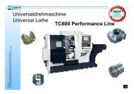
CNC Controllers
CNC Controllers
CNC Controllers

Create successful ePaper yourself
Turn your PDF publications into a flip-book with our unique Google optimized e-Paper software.
<strong>CNC</strong> <strong>Controllers</strong><br />
Specifications
Specifications<br />
5/1/04<br />
:Standard •:Standard option :Option :Function included in another option -:Not Available<br />
Note) Some combinations of these options are restricted.<br />
In case of 300i /310i /320i /300i s/310i s/320i s, using <strong>CNC</strong> Screen Display Function is a<br />
Controlled axis<br />
Item<br />
Specifications<br />
Drawing<br />
Number<br />
Series 30i -A<br />
Series 300i -A<br />
Series 300i s-A<br />
Milling<br />
path<br />
Turning<br />
path<br />
Series 31i -A5<br />
Series 310i -A5<br />
Series 310i s-A5<br />
Milling<br />
path<br />
Turning<br />
path<br />
Series 31i -A<br />
Series 310i -A<br />
Series 310i s-A<br />
Milling<br />
path<br />
Turning<br />
path<br />
Series 32i -A<br />
Series 320i -A<br />
Series 320i s-A<br />
Milling<br />
path<br />
Turning<br />
path<br />
Max. controlled axes<br />
(Machine controlled axes + Loader<br />
controlled axes)<br />
(Machine controlled axes are including<br />
Cs axes)<br />
32 axes J802 - - - - - -<br />
20 axes - - - -<br />
9 axes - - - - - - <br />
Machine groups 1group ◦ ◦ ◦ ◦ ◦ ◦ ◦ ◦<br />
Max. 3 groups S836 - -<br />
Max. 2 groups - - - - - - <br />
Control paths 1 path ◦ ◦ ◦ ◦ ◦ ◦ ◦ ◦<br />
Max. 10 path S801 - - - - - -<br />
Max. 4 path - - - -<br />
Max. 2 path - - - - - - <br />
Control axes(each path) 2 axes - ◦ - ◦ - ◦ - ◦<br />
3 axes ◦ - ◦ - ◦ - ◦ -<br />
Simultaneously controlled axes<br />
(each path)<br />
Simultaneous 2 axes ◦ ◦ ◦ ◦ ◦ ◦ ◦ ◦<br />
Controllable axes expansion<br />
Max. 24 axes J801 - - - - - -<br />
( each path )<br />
Max. 12 axes - - - -<br />
(including PMC axes and Cs axes)<br />
Max. 5 axes - - - - - - <br />
Max. 24 axes J803 - - - - - -<br />
Simultaneously controlled axes<br />
expansion( each path)<br />
Max. 5 axes - - - - - -<br />
Max. 4 axes - - - - <br />
Axis control by PMC Max. 32axes. (Not available on Cs axis) J804 - - - - - -<br />
Max. 16axes. (Not available on Cs axis) - - - -<br />
Max. 8axes. (Not available on Cs axis) - - - - - - <br />
Max. 4 axes / 8 axes S837 - - - - - -<br />
Designation of Spindle axes<br />
( each path / Total )<br />
Max. 4 axes / 6 axes - - - -<br />
Max. 2 axes / 2 axes - - - - - - <br />
Max. 4 axes / 8 axes J852 - - - - - -<br />
Cs contouring control<br />
( each path / Total )<br />
Max. 4 axes / 6 axes - - - -<br />
Max. 2 axes / 2 axes - - - - - - <br />
Controlled path for Loader Max. 8 path - - - - - -<br />
Max. 2 path - - - -<br />
Max. 1 path - - - - - - <br />
Controlled axes for Loader Max. 4 axes <br />
Simultaneously controlled axes for<br />
Loader<br />
Max. 4 axes <br />
Axis control by PMC for Loader Max. 4 axes <br />
Basic three axes are X, Y and Z,<br />
Axis name additional axes are optional from U,<br />
◦ - ◦ - ◦ - ◦ -<br />
V, W, A, B and C.<br />
In case of G code system A, basic 2<br />
axes are X and Z, additional axes<br />
- ◦ - ◦ - ◦ - ◦<br />
are optional from Y, A, B and C.<br />
In case of G code system B/C, basic<br />
2 axes are X and Z, additional axes<br />
are optional from Y, U, V, W, A, B<br />
- - - - <br />
and C.<br />
Axis name expansion Max 3 characters ◦ ◦ ◦ ◦ ◦ ◦ ◦ ◦<br />
Arbitary axis name setting Included in Custom macro function <br />
Max. 3 characters. Included<br />
Spindle name expansion<br />
<br />
in Multi-spindle function.<br />
Synchronous/Composite control S816 <br />
02/05 GFTE-585A-EN - 2 -
:Standard •:Standard option :Option :Function included in another option -:Not Available<br />
Note) Some combinations of these options are restricted.<br />
In case of 300i /310i /320i /300i s/310i s/320i s, using <strong>CNC</strong> Screen Display Function is a<br />
Item<br />
Specifications<br />
Drawing<br />
Number<br />
Series 30i -A<br />
Series 300i -A<br />
Series 300i s-A<br />
Milling<br />
path<br />
Turning<br />
path<br />
Series 31i -A5<br />
Series 310i -A5<br />
Series 310i s-A5<br />
Milling<br />
path<br />
Turning<br />
path<br />
Series 31i -A<br />
Series 310i -A<br />
Series 310i s-A<br />
Milling<br />
path<br />
Turning<br />
path<br />
Series 32i -A<br />
Series 320i -A<br />
Series 320i s-A<br />
Superimposed Control S818 <br />
Milling<br />
path<br />
Turning<br />
path<br />
Synchronous/Composite/Superimposed<br />
control by program command<br />
S890 <br />
Axis synchronous control Max. 12 pairs. J843 - - - - - -<br />
Max. 6 pairs. - - - -<br />
1 pairs. - - - - - - <br />
Twin table control *99 J698 - - - -<br />
Arbitrary angular axis control J924 <br />
Inclined Rotary Axis Control S688 - - - -<br />
Tandem control J733 <br />
Tandem Disturbance Elimination Control Axis synchronous control is required. S660 <br />
Torque control Included in PMC axis control. - -<br />
Pole Position Detection Function S744 <br />
Control axis detach J807 <br />
Chopping J707 - - - -<br />
Increment system IS-A, IS-B ◦ ◦ ◦ ◦ ◦ ◦ ◦ ◦<br />
Increment system C 0.0001mm、0.0001deg、0.00001inch J805 <br />
Increment system D 0.00001mm、0.00001deg、0.000001inch S694 <br />
Increment system E 0.000001mm、0.000001deg、0.0000001inch S805 - -<br />
Flexible feed gear Optional DMR ◦ ◦ ◦ ◦ ◦ ◦ ◦ ◦<br />
Arbitrary command multiply 1/9999 - 9999times S806 <br />
Learning control J705 - -<br />
Preview repetitive control J706 - -<br />
Learning control for parts cutting R510 - -<br />
Dual position feedback J704 <br />
HRV2 control ◦ ◦ ◦ ◦ ◦ ◦ ◦ ◦<br />
HRV3 control J398 <br />
HRV4 control J399 - -<br />
Inch/metric conversion J876 <br />
Interlock<br />
All / each axis, each direction,<br />
block start, cutting block start<br />
◦ ◦ ◦ ◦ ◦ ◦ ◦ ◦<br />
Machine lock all / each axis ◦ ◦ ◦ ◦ ◦ ◦ ◦ ◦<br />
Emergency stop ◦ ◦ ◦ ◦ ◦ ◦ ◦ ◦<br />
Over travel ◦ ◦ ◦ ◦ ◦ ◦ ◦ ◦<br />
Stored stroke check 1 ◦ ◦ ◦ ◦ ◦ ◦ ◦ ◦<br />
Stroke limit external setting J845 <br />
Stored stroke check 2,3 J840 <br />
Stored limit check before move J749 <br />
Chuck and tail stock barrier J720 - - - - <br />
Mirror image each axis ◦ ◦ ◦ ◦ ◦ ◦ ◦ ◦<br />
Follow-up ◦ ◦ ◦ ◦ ◦ ◦ ◦ ◦<br />
Servo off/Mechanical handle ◦ ◦ ◦ ◦ ◦ ◦ ◦ ◦<br />
Chamfering on/off - ◦ - ◦ - ◦ - ◦<br />
Interference check for each path Only for more than 2 path control J839 - - - - -<br />
Interference check for rotary area S643 - -<br />
Unexpected disturbance torque detection<br />
function<br />
J718 <br />
FANUC SERVO MOTOR β Series<br />
Unexpected distubance torque detection<br />
S812 <br />
Fine torque sensing *99 J982 - -<br />
Rotary axis control J743 - -<br />
02/05 GFTE-585A-EN - 3 -
:Standard •:Standard option :Option :Function included in another option -:Not Available<br />
Note) Some combinations of these options are restricted.<br />
In case of 300i /310i /320i /300i s/310i s/320i s, using <strong>CNC</strong> Screen Display Function is a<br />
Item<br />
Specifications<br />
Drawing<br />
Number<br />
Series 30i -A<br />
Series 300i -A<br />
Series 300i s-A<br />
Milling<br />
path<br />
Turning<br />
path<br />
Series 31i -A5<br />
Series 310i -A5<br />
Series 310i s-A5<br />
Milling<br />
path<br />
Turning<br />
path<br />
Series 31i -A<br />
Series 310i -A<br />
Series 310i s-A<br />
Milling<br />
path<br />
Turning<br />
path<br />
Series 32i -A<br />
Series 320i -A<br />
Series 320i s-A<br />
Position switch J846 <br />
High speed position switch J987 - -<br />
Direction-dependent type of<br />
high speed position switch<br />
S721 - -<br />
Linear scale I/F with absolute<br />
address reference mark<br />
J670 <br />
Linear scale I/F expansion with absolute<br />
address reference mark<br />
S730 <br />
Temporary absolute coordinate setting J786 <br />
Dual check safety<br />
I/O Link expansion 3rd channel is<br />
required.<br />
S661 <br />
Operation<br />
Automatic operation ◦ ◦ ◦ ◦ ◦ ◦ ◦ ◦<br />
MDI operation ◦ ◦ ◦ ◦ ◦ ◦ ◦ ◦<br />
DNC operation<br />
Reader/puncher interface<br />
is required.<br />
<br />
DNC operation with memory card<br />
CF card and PCMCIA Card<br />
Attachiment is required.<br />
*2 ◦ ◦ ◦ ◦ ◦ ◦ ◦ ◦<br />
Schedule function <br />
Program number search ◦ ◦ ◦ ◦ ◦ ◦ ◦ ◦<br />
Sequence number search ◦ ◦ ◦ ◦ ◦ ◦ ◦ ◦<br />
Sequence number comparison and stop J844 <br />
Program restart J838 <br />
Tool retract and recover J823 - -<br />
Wrong operation prevention ◦ ◦ ◦ ◦ ◦ ◦ ◦ ◦<br />
Retraction for Rigid tapping J664 <br />
Buffer register ◦ ◦ ◦ ◦ ◦ ◦ ◦ ◦<br />
Dry run ◦ ◦ ◦ ◦ ◦ ◦ ◦ ◦<br />
Single block ◦ ◦ ◦ ◦ ◦ ◦ ◦ ◦<br />
Manual continuous feed (JOG) ◦ ◦ ◦ ◦ ◦ ◦ ◦ ◦<br />
Manual reference position return ◦ ◦ ◦ ◦ ◦ ◦ ◦ ◦<br />
Reference position setting without DOG ◦ ◦ ◦ ◦ ◦ ◦ ◦ ◦<br />
Reference point setting with mechanical<br />
stopper<br />
J729 <br />
Reference position return speed set ◦ ◦ ◦ ◦ ◦ ◦ ◦ ◦<br />
Reference position shift ◦ ◦ ◦ ◦ ◦ ◦ ◦ ◦<br />
Manual handle feed 1-unit 1 unit J835 <br />
Manual handle feed 2/3-units 2 units/3 units J836 <br />
Manual handle feed rate<br />
×1、×10、×m 、×n<br />
m:0~2000、n:0~2000<br />
<br />
Manual feed for 5-axis machining S679 - - - -<br />
Handle interruption J837 <br />
FANUC SERVO MOTOR β Series<br />
with I/O Link<br />
S722 <br />
Manual handle interface<br />
Incremental feed ×1、×10、×100、×1000、×10000 ◦ ◦ ◦ ◦ ◦ ◦ ◦ ◦<br />
Jog and handle simultaneous mode <br />
Manual numerical command J667 - -<br />
Reference position signal output S629 <br />
Retrace J730 - - - -<br />
Manual handle retrace *99 J998 <br />
Manual liner/circular interpolation Only for 1path *99 <br />
Milling<br />
path<br />
Turning<br />
path<br />
02/05 GFTE-585A-EN - 4 -
:Standard •:Standard option :Option :Function included in another option -:Not Available<br />
Note) Some combinations of these options are restricted.<br />
In case of 300i /310i /320i /300i s/310i s/320i s, using <strong>CNC</strong> Screen Display Function is a<br />
Item<br />
Interpolation functions<br />
Specifications<br />
Drawing<br />
Number<br />
Series 30i -A<br />
Series 300i -A<br />
Series 300i s-A<br />
Milling<br />
path<br />
Turning<br />
path<br />
Series 31i -A5<br />
Series 310i -A5<br />
Series 310i s-A5<br />
Milling<br />
path<br />
Turning<br />
path<br />
Series 31i -A<br />
Series 310i -A<br />
Series 310i s-A<br />
Milling<br />
path<br />
Turning<br />
path<br />
Series 32i -A<br />
Series 320i -A<br />
Series 320i s-A<br />
Milling<br />
path<br />
Turning<br />
path<br />
Nano interpolation ◦ ◦ ◦ ◦ ◦ ◦ ◦ ◦<br />
Positioning<br />
G00 (Linear interpolation<br />
type positioning is possible)<br />
◦ ◦ ◦ ◦ ◦ ◦ ◦ ◦<br />
Single direction positioning G60 J812 <br />
Exact stop mode G61 ◦ ◦ ◦ ◦ ◦ ◦ ◦ ◦<br />
Tapping mode G63 ◦ ◦ ◦ ◦ ◦ ◦ ◦ ◦<br />
Cutting mode G64 ◦ ◦ ◦ ◦ ◦ ◦ ◦ ◦<br />
Exact stop G09 ◦ ◦ ◦ ◦ ◦ ◦ ◦ ◦<br />
Linear interpolation ◦ ◦ ◦ ◦ ◦ ◦ ◦ ◦<br />
Circular interpolation ◦ ◦ ◦ ◦ ◦ ◦ ◦ ◦<br />
Exponential interpolation J711 - -<br />
Dwell in seconds and dwell in<br />
revolution (In case of dwell in<br />
Dwell (Second designation) revolution for M system, threading,<br />
◦ ◦ ◦ ◦ ◦ ◦ ◦ ◦<br />
synchronous cutting option is<br />
required.)<br />
Polar coordinate interpolation J815 <br />
Cylindrical interpolation J816 <br />
Helical interpolation<br />
Circular interpolation plus max. 2<br />
axes linear interpolation<br />
J819 <br />
Circular interpolation plus max. 4<br />
Helical interpolation B J655 - - - - - -<br />
axes linear interpolation.<br />
Involutes interpolation J710 - -<br />
Hypothetical axis interpolation J652 - -<br />
Conical/spiral interpolation J780 - -<br />
Smooth interpolation J777 - -<br />
AI contour control I or II is<br />
Nano smoothing S687 - -<br />
AI<br />
required.<br />
contour control I or II is<br />
Nano smoothing for 5-axis machining R512 - - - -<br />
required<br />
Thread cutting, synchronous cutting Spindle serieal output is required. J824 ◦ ◦ ◦ ◦<br />
Multi threading ◦ ◦ ◦ ◦<br />
Thread cutting retract J825 <br />
Continuous threading ◦ ◦ ◦ ◦<br />
Variable lead thread cutting J827 <br />
Circular thread cutting J731 - -<br />
Polygon turning J817 <br />
Polygon machining with two spindles J708 <br />
Skip G31 ◦ ◦ ◦ ◦ ◦ ◦ ◦ ◦<br />
Multi-step skip J849 <br />
High-speed skip Input signal is 8 points. J848 <br />
Torque limit skip ◦ ◦ ◦ ◦ ◦ ◦ ◦ ◦<br />
Reference position return G28 ◦ ◦ ◦ ◦ ◦ ◦ ◦ ◦<br />
Reference position return check G27 ◦ ◦ ◦ ◦ ◦ ◦ ◦ ◦<br />
2nd reference position return ◦ ◦ ◦ ◦ ◦ ◦ ◦ ◦<br />
3rd/4th reference position return J830 <br />
Floating reference position return J831 - -<br />
Normal direction control J813 - - - -<br />
NURBS interpolation J669 - -<br />
3 dimensional circular interpolation S673 - - - -<br />
Balanced cutting Only for more than 2 path control J834 - - - - -<br />
Index table indexing J822 - - - -<br />
Continuous high-speed skip J770 - - - - -<br />
Gentle normal direction control J986 - - - - -<br />
Continuous dressing J630 - - - -<br />
02/05 GFTE-585A-EN - 5 -
:Standard •:Standard option :Option :Function included in another option -:Not Available<br />
Note) Some combinations of these options are restricted.<br />
In case of 300i /310i /320i /300i s/310i s/320i s, using <strong>CNC</strong> Screen Display Function is a<br />
Item<br />
Specifications<br />
Drawing<br />
Number<br />
Series 30i -A<br />
Series 300i -A<br />
Series 300i s-A<br />
Milling<br />
path<br />
Turning<br />
path<br />
Series 31i -A5<br />
Series 310i -A5<br />
Series 310i s-A5<br />
Milling<br />
path<br />
Turning<br />
path<br />
Series 31i -A<br />
Series 310i -A<br />
Series 310i s-A<br />
Milling<br />
path<br />
Turning<br />
path<br />
Series 32i -A<br />
Series 320i -A<br />
Series 320i s-A<br />
Infeed control J631 - - - -<br />
High-speed cycle cutting J832 - -<br />
General purpose retract J997 <br />
Feed function<br />
Rapid traverse rate Max. 999.999m/min(1µm) ◦ ◦ ◦ ◦ ◦ ◦ ◦ ◦<br />
Max. 99.9999m/min(0.1µm) <br />
Max. 99.9999m/min(0.01µm) <br />
Max. 99.9999m/min(0.001µm) - -<br />
Rapid traverse override Fo, 25, 50, 100% or 0~100%(1% Step) ◦ ◦ ◦ ◦ ◦ ◦ ◦ ◦<br />
Feed per minute ◦ ◦ ◦ ◦ ◦ ◦ ◦ ◦<br />
For M system, threading,<br />
Feed per revolution synchronous cutting option is<br />
◦ ◦ ◦ ◦<br />
required.<br />
Without position coder feed per<br />
Included in constant surface speed<br />
revolution<br />
control.<br />
<br />
Without position coder constant Included in constant surface speed<br />
surface speed control<br />
control.<br />
<br />
Tangential speed constant control ◦ ◦ ◦ ◦ ◦ ◦ ◦ ◦<br />
Cutting feedrate clamp ◦ ◦ ◦ ◦ ◦ ◦ ◦ ◦<br />
Automatic acceleration/deceleration<br />
Rapid traverse: linear<br />
Cutting feed: exponential, linear<br />
◦ ◦ ◦ ◦ ◦ ◦ ◦ ◦<br />
Rapid traverse bell-shaped<br />
acceleration/deceleration<br />
◦ ◦ ◦ ◦ ◦ ◦ ◦ ◦<br />
Optimum torque<br />
AI contour control I or II is<br />
acceleration/deceleration<br />
required.<br />
S675 <br />
Bell-shaped<br />
acceleration/deceleration<br />
J829 <br />
after cutting feed interpolation<br />
Linear acceleration/deceleration before Included in AI contour<br />
cutting feed interpolation<br />
control I or II<br />
<br />
Feedrate override 0 - 254% ◦ ◦ ◦ ◦ ◦ ◦ ◦ ◦<br />
2nd feedrate override 0 - 254% J810 - -<br />
One-digit F code feed J820 - - - -<br />
Inverse time feed J715 - - - -<br />
Jog override 0 - 655.34% ◦ ◦ ◦ ◦ ◦ ◦ ◦ ◦<br />
Override cancel ◦ ◦ ◦ ◦ ◦ ◦ ◦ ◦<br />
Manual per revolution feed - ◦ - ◦ - ◦ - ◦<br />
External deceleration J842 <br />
Feed stop J847 - -<br />
Automatic corner deceleration Included in AI contour control I or II <br />
Feedrate clamp by circular radius Included in AI contour control I or II <br />
Linear acc/dec after cutting feed<br />
interpolation<br />
◦ ◦ ◦ ◦ ◦ ◦ ◦ ◦<br />
AI contour control I Look-ahead block no. is Max .30 S807 <br />
Look-ahead block no. is Max .200<br />
AI contour control II<br />
(32i Max.80)<br />
(Path number
:Standard •:Standard option :Option :Function included in another option -:Not Available<br />
Note) Some combinations of these options are restricted.<br />
In case of 300i /310i /320i /300i s/310i s/320i s, using <strong>CNC</strong> Screen Display Function is a<br />
Program input<br />
Item<br />
Specifications<br />
Drawing<br />
Number<br />
Series 30i -A<br />
Series 300i -A<br />
Series 300i s-A<br />
Milling<br />
path<br />
Turning<br />
path<br />
Series 31i -A5<br />
Series 310i -A5<br />
Series 310i s-A5<br />
Milling<br />
path<br />
Turning<br />
path<br />
Series 31i -A<br />
Series 310i -A<br />
Series 310i s-A<br />
Milling<br />
path<br />
Turning<br />
path<br />
Series 32i -A<br />
Series 320i -A<br />
Series 320i s-A<br />
Milling<br />
path<br />
Turning<br />
path<br />
Tape code EIA/ISO ◦ ◦ ◦ ◦ ◦ ◦ ◦ ◦<br />
Label skip ◦ ◦ ◦ ◦ ◦ ◦ ◦ ◦<br />
Parity check Horizontal and vertical parity ◦ ◦ ◦ ◦ ◦ ◦ ◦ ◦<br />
Control in/out ◦ ◦ ◦ ◦ ◦ ◦ ◦ ◦<br />
Optional block skip 1 ◦ ◦ ◦ ◦ ◦ ◦ ◦ ◦<br />
Optional block skip 9 J955 <br />
Max. programmable dimension ±9 digit (R,I,J and K is ±12digit ) ◦ ◦ ◦ ◦ ◦ ◦ ◦ ◦<br />
Program file name 32 characters ◦ ◦ ◦ ◦ ◦ ◦ ◦ ◦<br />
Sequence number N8 digit ◦ ◦ ◦ ◦ ◦ ◦ ◦ ◦<br />
Absolute/incremental programming Combined use in the same block ◦ ◦ ◦ ◦ ◦ ◦ ◦ ◦<br />
Decimal point programming/pocket<br />
calculator type decimal point<br />
programming<br />
◦ ◦ ◦ ◦ ◦ ◦ ◦ ◦<br />
Input unit 10 time multiply ◦ ◦ ◦ ◦ ◦ ◦ ◦ ◦<br />
Diameter/Radius programming ◦ ◦ ◦ ◦ ◦ ◦ ◦ ◦<br />
Dynamic swithching of diameter/radius<br />
specification<br />
S630 - -<br />
Plane selection G17、G18、G19 ◦ ◦ ◦ ◦ ◦ ◦ ◦ ◦<br />
Rotary axis designation ◦ ◦ ◦ ◦ ◦ ◦ ◦ ◦<br />
Rotary axis roll-over ◦ ◦ ◦ ◦ ◦ ◦ ◦ ◦<br />
Polar coordinate command J818 - - - -<br />
Coordinate system setting ◦ ◦ ◦ ◦ ◦ ◦ ◦ ◦<br />
Automatic coordinate system setting ◦ ◦ ◦ ◦ ◦ ◦ ◦ ◦<br />
Workpiece coordinate system G52 - G59 J894 <br />
Workpiece coordinate system preset J917 <br />
Addition of workpiece coordinate system<br />
48-pairs<br />
48 pairs J895 <br />
Addition of workpiece coordinate system<br />
300-pairs<br />
300 pairs J919 - -<br />
Direct input of workpiece orgin offset<br />
value measured<br />
Included in workpiece coordinate system.<br />
<br />
Manual absolute on and off ◦ ◦ ◦ ◦ ◦ ◦ ◦ ◦<br />
Direct drawing dimension programming J870 - - - - <br />
G code system A - ◦ - ◦ - ◦ - ◦<br />
G code system B/C J871 - - - - <br />
Chamfering/Corner R J875 - - - - <br />
Optional chamfering corner R S615 - - - -<br />
Programmable data input G10 ◦ ◦ ◦ ◦ ◦ ◦ ◦ ◦<br />
Programmable parameter input ◦ ◦ ◦ ◦ ◦ ◦ ◦ ◦<br />
Sub program call 10 folds nested ◦ ◦ ◦ ◦ ◦ ◦ ◦ ◦<br />
Custom macro J873 <br />
Addition of custom macro common<br />
variables<br />
#100 - #199、#500 - #999 J887 <br />
Custom macro common variables<br />
between each path<br />
Only for more than 2 path control <br />
Interruption type custom macro J874 <br />
Canned cycle - ◦ - ◦ - ◦ - ◦<br />
Multiple repetitive cycles J877 - - - - <br />
Multiple repetitive cycles II Pocket profile J889 - - - - <br />
Canned cycle for drilling J890 <br />
Circular interpolation by R programming R,I,J,K 12digit ◦ ◦ ◦ ◦ ◦ ◦ ◦ ◦<br />
Mirror image for double turret J881 - - - - <br />
Automatic corner override J891 <br />
Scaling J892 <br />
Coordinate system rotation J893 <br />
02/05 GFTE-585A-EN - 7 -
:Standard •:Standard option :Option :Function included in another option -:Not Available<br />
Note) Some combinations of these options are restricted.<br />
In case of 300i /310i /320i /300i s/310i s/320i s, using <strong>CNC</strong> Screen Display Function is a<br />
Item<br />
Specifications<br />
Drawing<br />
Number<br />
Series 30i -A<br />
Series 300i -A<br />
Series 300i s-A<br />
Milling<br />
path<br />
Turning<br />
path<br />
Series 31i -A5<br />
Series 310i -A5<br />
Series 310i s-A5<br />
Milling<br />
path<br />
Turning<br />
path<br />
Series 31i -A<br />
Series 310i -A<br />
Series 310i s-A<br />
Milling<br />
path<br />
Turning<br />
path<br />
Series 32i -A<br />
Series 320i -A<br />
Series 320i s-A<br />
3-dimensional coordinate system<br />
conversion<br />
J713 <br />
Tilted working plane command S676 - -<br />
Programmable mirror image J880 <br />
Figure copying J897 - - - - -<br />
Tape format for FS15 J882 - -<br />
Tape format for FS10/11 J882 - - - - - - <br />
Macro executor J888 <br />
C-language executor J734 <br />
SRAM Extension for C-executor J736 <br />
Custom software<br />
256KByte<br />
J738<br />
#256K<br />
<br />
512KByte<br />
J738<br />
#512K<br />
<br />
1MByte J738#1M <br />
2MByte J738#2M <br />
3Mbyte J738#3M <br />
4MByte J738#4M <br />
5MByte J738#5M - -<br />
6MByte J738#6M - -<br />
Coordinate system shift - ◦ - ◦ - ◦ - ◦<br />
Direct input of coordinate system shift - ◦ - ◦ - ◦ - ◦<br />
Embedded macro *99 S652 <br />
Embedded macro for milling Embedded macro is required. *99 S654 - - - -<br />
Small-hole peck drilling cycle J896 - - - -<br />
Canned cycles for grinding J640 <br />
Real time custom macro S842 <br />
Pattern data input *99 <br />
Integrated Operation guidance function<br />
MANUAL GUIDE i S780 <br />
MANUAL GUIDE i Basic S781 <br />
MANUAL GUIDE i Milling Cycle S782 <br />
MANUAL GUIDE i Turning Cycle S783 - - - - <br />
MANUAL GUIDE i Animation S784 <br />
MANUAL GUIDE i Set-up Guidance *99 S785 <br />
MANUAL GUIDE i Multi path lathe *99 S786 - - - - <br />
Auxiliary/Spindle speed function<br />
Auxiliary function M8 digit ◦ ◦ ◦ ◦ ◦ ◦ ◦ ◦<br />
2nd auxiliary function B8 digit J920 <br />
Auxiliary function lock ◦ ◦ ◦ ◦ ◦ ◦ ◦ ◦<br />
High-speed M/S/T/B interface ◦ ◦ ◦ ◦ ◦ ◦ ◦ ◦<br />
Waiting function Only for more than 2 path con ◦ ◦ ◦ ◦ ◦ ◦ ◦ ◦<br />
Multiple command of auxiliary function 3 ◦ ◦ ◦ ◦ ◦ ◦ ◦ ◦<br />
Spindle speed function S5 digit , binary output ◦ ◦ ◦ ◦ ◦ ◦ ◦ ◦<br />
Spindle serial output S5 digit , serial output (max. 8 spindles) J850 - - - - - -<br />
S5 digit , serial output (max. 6 spindles)<br />
- - - -<br />
S5 digit , serial output (max. 2 spindles)<br />
- - - - - - <br />
Constant surface speed control J855 <br />
Spindle override 0 - 254% <br />
Actual spindle speed output J856 <br />
Spindle orientation 1 spindle J853 <br />
Spindle orientation expansion Max. 8 spindles J861 - - - - - -<br />
Max. 6 spindles - - - -<br />
02/05 GFTE-585A-EN - 8 -<br />
Milling<br />
path<br />
Turning<br />
path
:Standard •:Standard option :Option :Function included in another option -:Not Available<br />
Note) Some combinations of these options are restricted.<br />
In case of 300i /310i /320i /300i s/310i s/320i s, using <strong>CNC</strong> Screen Display Function is a<br />
Item<br />
Specifications<br />
Drawing<br />
Number<br />
Series 30i -A<br />
Series 300i -A<br />
Series 300i s-A<br />
Milling<br />
path<br />
Turning<br />
path<br />
Series 31i -A5<br />
Series 310i -A5<br />
Series 310i s-A5<br />
Milling<br />
path<br />
Turning<br />
path<br />
Series 31i -A<br />
Series 310i -A<br />
Series 310i s-A<br />
Milling<br />
path<br />
Turning<br />
path<br />
Series 32i -A<br />
Series 320i -A<br />
Series 320i s-A<br />
Max. 2 spindles - - - - - - <br />
Spindle output switching function 1 spindle J854 <br />
Spindle output switching function<br />
expansion<br />
Max. 8 spindles J862 - - - - - -<br />
Max. 6 spindles - - - -<br />
Max. 2 spindles - - - - - - <br />
Spindle synchronous control J858 <br />
Simple spindle synchronous control J748 <br />
Multi spindle control J859 <br />
Spindle positioning J851 <br />
Rigid tap J828 <br />
Rigid tapping by manual handle J651 - -<br />
Arbitrary position reference setting for CS<br />
axis<br />
S664 - -<br />
M code group check J922 - -<br />
Spindle speed fluctuation detection J857 <br />
Live tool control with servo motor J978 <br />
Tool function/Tool compensation<br />
Tool function T7+1/T6+2/T5+3 - ◦ - ◦ - ◦ - ◦<br />
Tool function T8 digit ◦ - ◦ - ◦ - ◦ -<br />
Tool offset pairs<br />
(Note)<br />
Specify total of tool offset pairs of each<br />
path. Max. digit of tool offset is 9.<br />
32 ◦ ◦ ◦ ◦ ◦ ◦ ◦ ◦<br />
Tool offset pairs 64-pairs 64 J925 <br />
Tool offset pairs 99-pairs 99 J926 <br />
Tool offset pairs 200-pairs 200 J927 <br />
Tool offset pairs 400-pairs 400 J928 <br />
Tool offset pairs 499-pairs 499 S614 - -<br />
Tool offset pairs 999-pairs 999 J721 - -<br />
Tool offset pairs 2000-pairs 2000 S622 - -<br />
Tool offset memory B Geometry/wear memory S616 - - - -<br />
Tool offset memory C<br />
Distinction between geometry and<br />
wear, or between cutter and tool J937 - - - -<br />
length compensation.<br />
Common offset memory between each<br />
path<br />
Only for more than 2 path control ◦ ◦ ◦ ◦ ◦ ◦ ◦ ◦<br />
Tool length offset ◦ - ◦ - ◦ - ◦ -<br />
Tool offset S617 ◦ ◦ ◦ ◦<br />
Tool center point control for 5-axis<br />
machining<br />
S677 - - - -<br />
Tool posture control for Tool center point<br />
control for 5-axis machining<br />
S994 - - - -<br />
Y-axis offset J934 - - - - <br />
Tool radius・Tool nose radius<br />
compensation<br />
J930 <br />
3-dimensional tool compensation J727 - - - - -<br />
Cutting point interpolation for<br />
cylindrical interpolation<br />
S674 - -<br />
Tool geometry/wear compensation J931 - - - - <br />
2nd Geometry Tool Offset<br />
Tool geometry/wear compensation<br />
is required<br />
J980 - - - - <br />
Tool pair for tool management function:<br />
64 pairs<br />
64 tools S830 <br />
Tool pair for tool management function:<br />
240 pairs<br />
240 tools S831 <br />
Tool pair for tool management function:<br />
1000 pairs<br />
1000 tools S833 <br />
Tool management function:<br />
Customized data expansion(5~20)<br />
S834 <br />
Milling<br />
path<br />
Turning<br />
path<br />
02/05 GFTE-585A-EN - 9 -
:Standard •:Standard option :Option :Function included in another option -:Not Available<br />
Note) Some combinations of these options are restricted.<br />
In case of 300i /310i /320i /300i s/310i s/320i s, using <strong>CNC</strong> Screen Display Function is a<br />
Item<br />
Specifications<br />
Drawing<br />
Number<br />
Series 30i -A<br />
Series 300i -A<br />
Series 300i s-A<br />
Milling<br />
path<br />
Turning<br />
path<br />
Series 31i -A5<br />
Series 310i -A5<br />
Series 310i s-A5<br />
Milling<br />
path<br />
Turning<br />
path<br />
Series 31i -A<br />
Series 310i -A<br />
Series 310i s-A<br />
Milling<br />
path<br />
Turning<br />
path<br />
Series 32i -A<br />
Series 320i -A<br />
Series 320i s-A<br />
Tool management function:<br />
Customized data expansion(5~40)<br />
S835 <br />
Tool management expansion S852 <br />
Tool management function for oversize<br />
tools<br />
S602 <br />
Tool management tool<br />
attachment/detachment function<br />
S997 <br />
Tool offset value counter input - ◦ - ◦ - ◦ - ◦<br />
Tool length measurement ◦ - ◦ - ◦ - ◦ -<br />
Automatic tool length measurement S618 - - - -<br />
Tool length/work zero point measurement J668 - - - - -<br />
Automatic tool offset J932 - - - - <br />
Direct input of tool offset value measured - ◦ - ◦ - ◦ - ◦<br />
Direct input of offset value measured B J933 - - - - <br />
Rotary table dynamic fixture offset S728 - - - - -<br />
Changing Active Offset Value with<br />
Manual Move<br />
S825 <br />
Tool length compensation in tool axis<br />
direction<br />
S670 - - - - -<br />
Work setting error compensation S993 - -<br />
Tool radius compensation for 5-axis<br />
machining<br />
S667 - - - -<br />
Measurement cycle Embedded macro *99 S663 - - - -<br />
Wheel wear compensation J633 - - - - -<br />
Direct input of offset value<br />
measured B for 2 spindle lathe<br />
J686 - - - - <br />
Tool life management J935 <br />
Addition of tool pairs for tool life<br />
management<br />
Max. 1024 pairs J936 <br />
Accuracy compensasion function<br />
Backlash compensation ◦ ◦ ◦ ◦ ◦ ◦ ◦ ◦<br />
Backlash compensation for each rapid<br />
traverse and cutting feed<br />
◦ ◦ ◦ ◦ ◦ ◦ ◦ ◦<br />
Smooth backlash compensation ◦ ◦ ◦ ◦ ◦ ◦ ◦ ◦<br />
Stored pitch error compensation J841 <br />
Interpolation type pitch error<br />
Stored pitch error compensation is<br />
S644 - -<br />
compensation<br />
required.<br />
Stored pitch error compensation is<br />
Bi-directional pitch error compensation S656 <br />
required.<br />
Extended bi-directional pitch error<br />
compensation<br />
Periodical secondary pitch error<br />
compensation<br />
Hobbing/Electric gear box<br />
Stored pitch error compensation, Bidirectional<br />
pitch error compensation<br />
are required.<br />
Stored pitch error compensation is<br />
required.<br />
Milling<br />
path<br />
Turning<br />
path<br />
S657 <br />
S634 - -<br />
Inclination compensation<br />
Stored pitch error compensation is<br />
required.<br />
J981 <br />
Straightness compensation<br />
Stored pitch error compensation is<br />
required.<br />
J747 - -<br />
128points.<br />
Interpolation type straightness<br />
Stored pitch error compensation is<br />
compensation<br />
required.<br />
S639 - -<br />
3-dimensional error compensation<br />
Stored pitch error compensation is<br />
required.<br />
S666 - -<br />
Thermal Growth Compensation Along<br />
Tool Vector<br />
S860 - -<br />
Simple electric gear box J779 <br />
Skip function for EGB axis J696 - -<br />
Electric gear box 2 pair S710 - -<br />
Electric gear box automatic phase<br />
synchronization<br />
S711 - -<br />
Spindle electric gear box *99 S720 - -<br />
02/05 GFTE-585A-EN - 10 -
:Standard •:Standard option :Option :Function included in another option -:Not Available<br />
Note) Some combinations of these options are restricted.<br />
In case of 300i /310i /320i /300i s/310i s/320i s, using <strong>CNC</strong> Screen Display Function is a<br />
Item<br />
Specifications<br />
Drawing<br />
Number<br />
Series 30i -A<br />
Series 300i -A<br />
Series 300i s-A<br />
Milling<br />
path<br />
Turning<br />
path<br />
Series 31i -A5<br />
Series 310i -A5<br />
Series 310i s-A5<br />
Milling<br />
path<br />
Turning<br />
path<br />
Series 31i -A<br />
Series 310i -A<br />
Series 310i s-A<br />
Milling<br />
path<br />
Turning<br />
path<br />
Series 32i -A<br />
Series 320i -A<br />
Series 320i s-A<br />
Flexible synchronous control S709 - -<br />
Editing operation<br />
32Kbyte - - - - - - ◦ ◦<br />
64Kbyte J943 ◦ ◦ ◦ ◦ ◦ ◦ <br />
Part program storage size *3<br />
128Kbyte J944 <br />
(Note)<br />
256Kbyte J945 <br />
Specify total of part program storage size 512Kbyte J946 <br />
of each path.<br />
1Mbyte J947 <br />
2Mbyte J948 <br />
4Mbyte J949 - -<br />
8Mbyte J959 - -<br />
Number of registerable programs 63 ◦ ◦ ◦ ◦ ◦ ◦ ◦ ◦<br />
Number of registerable programs<br />
expansion 1<br />
Max. 1000 programs J953 <br />
Number of registerable programs<br />
expansion 2<br />
Max 4000 programs J954 - -<br />
Part program editing ◦ ◦ ◦ ◦ ◦ ◦ ◦ ◦<br />
Program protect ◦ ◦ ◦ ◦ ◦ ◦ ◦ ◦<br />
Key and progrm encryption J778 - -<br />
Extended part program editing ◦ ◦ ◦ ◦ ◦ ◦ ◦ ◦<br />
Playback J879 <br />
Machining time stamp J964 - -<br />
Backgriound editting J956 <br />
Including background editing<br />
Multi part program editting only available on 15"and 10" display<br />
<br />
unit<br />
Memory card program edit & operation<br />
Max 63 progrmas. The tool on PC<br />
is required to convert and store files<br />
◦ ◦ ◦ ◦ ◦ ◦ ◦ ◦<br />
Memory card program entry count<br />
extension<br />
Max. 1000 programs S995 <br />
Setting and display<br />
Status display ◦ ◦ ◦ ◦ ◦ ◦ ◦ ◦<br />
Clock function ◦ ◦ ◦ ◦ ◦ ◦ ◦ ◦<br />
Current position display ◦ ◦ ◦ ◦ ◦ ◦ ◦ ◦<br />
Program commnent display Program name 31 characters<br />
◦ ◦ ◦ ◦ ◦ ◦ ◦ ◦<br />
Parameter setting and dispaly ◦ ◦ ◦ ◦ ◦ ◦ ◦ ◦<br />
Alarm display ◦ ◦ ◦ ◦ ◦ ◦ ◦ ◦<br />
Alarm history display ◦ ◦ ◦ ◦ ◦ ◦ ◦ ◦<br />
Operator message history display<br />
External message or external data<br />
input is required.<br />
<br />
Operation history display ◦ ◦ ◦ ◦ ◦ ◦ ◦ ◦<br />
・Machine remote diagnosis<br />
Remote diagnostic<br />
package + Ethernet<br />
(Function:Reading <strong>CNC</strong>/PMC<br />
<br />
status, etc.)<br />
Run hour and parts count display J971 <br />
Actual cutting feedrate display ◦ ◦ ◦ ◦ ◦ ◦ ◦ ◦<br />
Display of spindle speed and T code at<br />
all screens<br />
◦ ◦ ◦ ◦<br />
Directory display of floppy cassette<br />
Included in reader/puncher<br />
interface<br />
<br />
Optional path name display Only for more than 2 path control ◦ ◦ ◦ ◦ ◦ ◦ ◦ ◦<br />
Operating monitor screen Load meter etc. ◦ ◦ ◦ ◦ ◦ ◦ ◦ ◦<br />
Servo setting screen ◦ ◦ ◦ ◦ ◦ ◦ ◦ ◦<br />
Spindle setting screen Only for αi series <br />
Servo waveform display ◦ ◦ ◦ ◦ ◦ ◦ ◦ ◦<br />
Maintenance information screen ◦ ◦ ◦ ◦ ◦ ◦ ◦ ◦<br />
Software operator's panel J960 <br />
Software operator's panel<br />
general purpose switch<br />
Software operator's panel is<br />
required.<br />
02/05 GFTE-585A-EN - 11 -<br />
Milling<br />
path<br />
Turning<br />
path<br />
J961
:Standard •:Standard option :Option :Function included in another option -:Not Available<br />
Note) Some combinations of these options are restricted.<br />
In case of 300i /310i /320i /300i s/310i s/320i s, using <strong>CNC</strong> Screen Display Function is a<br />
Item<br />
Extended software operator's panel<br />
general purpose switch<br />
Specifications<br />
Drawing<br />
Number<br />
Series 30i -A<br />
Series 300i -A<br />
Series 300i s-A<br />
Milling<br />
path<br />
Turning<br />
path<br />
Series 31i -A5<br />
Series 310i -A5<br />
Series 310i s-A5<br />
Milling<br />
path<br />
Turning<br />
path<br />
Series 31i -A<br />
Series 310i -A<br />
Series 310i s-A<br />
Milling<br />
path<br />
Turning<br />
path<br />
Series 32i -A<br />
Series 320i -A<br />
Series 320i s-A<br />
Milling<br />
path<br />
Turning<br />
path<br />
<br />
Machine operation menu S844 <br />
Multi-language display English ◦ ◦ ◦ ◦ ◦ ◦ ◦ ◦<br />
Japanese J965 <br />
German S839 <br />
French S841 <br />
Spanish J970 <br />
Italian J968 <br />
Chinese J967 <br />
Chinese(simplified characters) S829 <br />
Korean J969 <br />
Portuguese J678 <br />
Dutch J962 <br />
Danish J650 <br />
Swedish S691 <br />
Hungarian S690 <br />
Czech S689 <br />
Polish S739 <br />
Dynamic display language switching included in Multi-Language display <br />
Data protection key 4 types ◦ ◦ ◦ ◦ ◦ ◦ ◦ ◦<br />
Protection of Data at Eight Levels S828 <br />
Erase CRT screen display Manual or Automatic *1 ◦ ◦ ◦ ◦ ◦ ◦ ◦ ◦<br />
Parameter set supporting screen ◦ ◦ ◦ ◦ ◦ ◦ ◦ ◦<br />
Machining condition selecting function<br />
AI contour control I or II is<br />
required.<br />
S637 <br />
Help function ◦ ◦ ◦ ◦ ◦ ◦ ◦ ◦<br />
Self-diagnosis function ◦ ◦ ◦ ◦ ◦ ◦ ◦ ◦<br />
Periodic maintenance screen ◦ ◦ ◦ ◦ ◦ ◦ ◦ ◦<br />
Display of hardware and software<br />
configuration<br />
◦ ◦ ◦ ◦ ◦ ◦ ◦ ◦<br />
Servo information screen ◦ ◦ ◦ ◦ ◦ ◦ ◦ ◦<br />
Spindle information screen <br />
Trouble diagnosis *99 <br />
Machine alarm diagnosis *99 S813 <br />
Graphic function J972 <br />
touch panel control *99 J682 <br />
External touch panel interface J685 <br />
Virtual MDI Key S882 <br />
Data input/output<br />
Included in software operator's<br />
panel general purpose switch<br />
Reader/puncher interface<br />
Reader/puncher (Ch.1)<br />
interface<br />
J900 <br />
Reader/puncher interface<br />
Reader/puncher (Ch.2)<br />
interface<br />
J901 <br />
Fast data server<br />
Only 1 path control/Option<br />
board is required<br />
S737 <br />
Data server buffer mode Fast data server is required J728 - -<br />
External tool offset J910 <br />
External machine zero point shift J912 <br />
External message J911 <br />
Including External tool offset,<br />
External data input External tool offset, and External J913 <br />
message.<br />
External key input ◦ ◦ ◦ ◦ ◦ ◦ ◦ ◦<br />
External workpiece number search 9999 ◦ ◦ ◦ ◦ ◦ ◦ ◦ ◦<br />
External program number search 1 - 9999 <br />
02/05 GFTE-585A-EN - 12 -
:Standard •:Standard option :Option :Function included in another option -:Not Available<br />
Note) Some combinations of these options are restricted.<br />
In case of 300i /310i /320i /300i s/310i s/320i s, using <strong>CNC</strong> Screen Display Function is a<br />
Item<br />
Specifications<br />
Drawing<br />
Number<br />
Series 30i -A<br />
Series 300i -A<br />
Series 300i s-A<br />
Milling<br />
path<br />
Turning<br />
path<br />
Series 31i -A5<br />
Series 310i -A5<br />
Series 310i s-A5<br />
Milling<br />
path<br />
Turning<br />
path<br />
Series 31i -A<br />
Series 310i -A<br />
Series 310i s-A<br />
Milling<br />
path<br />
Turning<br />
path<br />
Series 32i -A<br />
Series 320i -A<br />
Series 320i s-A<br />
Memory card input/output ◦ ◦ ◦ ◦ ◦ ◦ ◦ ◦<br />
Screen hard copy *2 ◦ ◦ ◦ ◦ ◦ ◦ ◦ ◦<br />
Power Mate <strong>CNC</strong> manager J674 <br />
External I/O device control J902 <br />
One touch macro call S655 <br />
Automatic data backup ◦ ◦ ◦ ◦ ◦ ◦ ◦ ◦<br />
Interface function<br />
Embedded Ethernet ◦ ◦ ◦ ◦ ◦ ◦ <br />
Fast Ethernet Option board is required. S707 <br />
PROFIBUS-DP master Option board is required. S731 <br />
PROFIBUS-DP slave Option board is required. S732 <br />
DeviceNet master Option board is required. S723 <br />
DeviceNet slave Option board is required. *99 <br />
FL-net Option board is required. J692 <br />
Others<br />
NC ready, servo ready, automatic<br />
operation, automatic operation start<br />
Status output signal lamp, feed hold, reset, NC alarm,<br />
◦ ◦ ◦ ◦ ◦ ◦ ◦ ◦<br />
distribution end, rewinding, inch<br />
input, cutting, inposition, thread<br />
7.2" monochrome LCD • • • • • • • •<br />
Control unit incorporated type display unit<br />
8.4" color LCD • • • • • • • •<br />
*8 *9<br />
10.4" color LCD • • • • • • • •<br />
(Not available in 300i)<br />
15" color LCD • • • • • • • •<br />
Without option slots<br />
• • • • • • • •<br />
Control unit dimensions for<br />
LCD unit mounted type<br />
(depth)<br />
Stand–alone type display<br />
*8 *10<br />
Stand–alone type control unit<br />
(width)<br />
(depth 60mm except 15"LCD)<br />
Milling<br />
path<br />
Turning<br />
path<br />
Option 1 slots<br />
(depth 90mm except 15"LCD)<br />
• • • • • • • •<br />
Option 2 slots<br />
(depth 110mm except 15"LCD)<br />
• • • • • • • •<br />
10.4" color LCD • • • • • • • •<br />
15" color LCD • • • • • • • •<br />
Option 2 slots<br />
(width 60mm)<br />
• • • • • • • •<br />
Option 4 slots<br />
(width 90mm)<br />
• • • • • • • •<br />
Separate MDI<br />
(ONG small, horizontal type) *1<br />
• • • • • • • •<br />
02/05 GFTE-585A-EN - 13 -
:Standard •:Standard option :Option :Function included in another option -:Not Available<br />
Note) Some combinations of these options are restricted.<br />
In case of 300i /310i /320i /300i s/310i s/320i s, using <strong>CNC</strong> Screen Display Function is a<br />
Item<br />
Specifications<br />
Drawing<br />
Number<br />
Series 30i -A<br />
Series 300i -A<br />
Series 300i s-A<br />
Milling<br />
path<br />
Turning<br />
path<br />
Series 31i -A5<br />
Series 310i -A5<br />
Series 310i s-A5<br />
Milling<br />
path<br />
Turning<br />
path<br />
Series 31i -A<br />
Series 310i -A<br />
Series 310i s-A<br />
Milling<br />
path<br />
Turning<br />
path<br />
Series 32i -A<br />
Series 320i -A<br />
Series 320i s-A<br />
Separate MDI<br />
MDI unit<br />
(ONG vertical type,<br />
• • • • • • • •<br />
*1<br />
horizontal type)<br />
Separate MDI (personal<br />
computer key, vertical type)<br />
• • • • • • • •<br />
Touch panel Only for 10.4", 15" LCD *9*10 • • • • • • • •<br />
1st PMC path<br />
2nd PMC path<br />
3rd PMC path<br />
1st path PMC message display<br />
function<br />
2nd path PMC message display<br />
function<br />
3rd path PMC message display<br />
function<br />
I/O Link expansion 2nd channel<br />
Basic instruction:<br />
25nsec/step<br />
Max. step number ladder:<br />
64000<br />
Basic instruction:<br />
25nsec/step<br />
Max. step number ladder:<br />
64000<br />
Basic instruction:<br />
25nsec/step<br />
Max. step number ladder:<br />
64000<br />
128Kbyte<br />
256Kbyte<br />
128Kbyte<br />
128Kbyte<br />
DI/DO points:<br />
addition 1024/1024 points<br />
S977<br />
#128K<br />
S977<br />
#256K<br />
S978<br />
#128K<br />
S979<br />
#128K<br />
Milling<br />
path<br />
Turning<br />
path<br />
• • • • • • • •<br />
<br />
<br />
<br />
<br />
<br />
<br />
S981 <br />
I/O Link expansion 3rd channel<br />
DI/DO points:<br />
addition 1024/1024 points<br />
S985 <br />
I/O Link expansion 4th channel<br />
DI/DO points:<br />
addition 1024/1024 points<br />
S986 - - - - - -<br />
Step sequence Only 1st PMC path S982 <br />
Nonvolatile PMC extra relay function S984 <br />
Standard operator's panel <br />
Machine interface (I/O Link)<br />
Max. DI/DO points:<br />
4096/4096 points (FS30i)<br />
3072/3072 points (FS31i/32i)<br />
(Note) If using more than 1024/1024<br />
points, I/O Link expansion option is<br />
necessary.<br />
(For expanding 4096/4096 points, option<br />
board is required. )<br />
I/O Unit-MODEL A<br />
I/O Unit-MODEL B<br />
Operator's panel I/O module<br />
Total 112,000 steps<br />
for 3 paths<br />
Power magnetics control I/O module<br />
Connection panel I/O module<br />
(DI/DO module, 2A output module,<br />
Analog input module)<br />
• • • • • • • •<br />
• • • • • • • •<br />
• • • • • • • •<br />
• • • • • • • •<br />
• • • • • • • •<br />
I/O Link - AS-i converter <br />
Manula pulse generator <br />
Pendant type manual pulse generator<br />
With axis selection and<br />
magnification switches<br />
<br />
Handy machine operator’s panel <br />
FANUC AC servo motor<br />
Connectable servo motor αi S series, αi series,<br />
◦ ◦ ◦ ◦ ◦ ◦ ◦ ◦<br />
βi s series<br />
FANUC servo amplifier<br />
Connectable servo amplifier αi series SVM (for 30i /31i /32i ),<br />
◦ ◦ ◦ ◦ ◦ ◦ ◦ ◦<br />
βi series SVM<br />
A quad B rectangle wave interface<br />
for rotary/linear encoder<br />
<br />
Separate detector I/F unit for full-closed FANUC serial interface for rotary<br />
control<br />
/linear encoder<br />
<br />
Analog 1Vp-p interface for rotary<br />
/linear encoder<br />
<br />
Connectable spindle motor<br />
FANUC AC spindle motor<br />
αi series<br />
◦ ◦ ◦ ◦ ◦ ◦ ◦ ◦<br />
Connectable spindle amplifier<br />
FANUC servo amplifier<br />
αi series<br />
<br />
Input power supply DC24V±10% • • • • • • • •<br />
LCD mounted type control unit,<br />
display unit for stand-alone type<br />
control unit<br />
• • • • • • • •<br />
Ambient temperature of unit *10<br />
At operating: 0℃ - 58℃<br />
At nonoperating: -20℃ - 60℃<br />
02/05 GFTE-585A-EN - 14 -
:Standard •:Standard option :Option :Function included in another option -:Not Available<br />
Note) Some combinations of these options are restricted.<br />
In case of 300i /310i /320i /300i s/310i s/320i s, using <strong>CNC</strong> Screen Display Function is a<br />
Item<br />
Specifications<br />
Stand alone type control unit<br />
At operating: 0℃ - 55℃<br />
At nonoperating: -20℃ - 60℃<br />
Drawing<br />
Number<br />
Series 30i -A<br />
Series 300i -A<br />
Series 300i s-A<br />
Milling<br />
path<br />
Turning<br />
path<br />
Series 31i -A5<br />
Series 310i -A5<br />
Series 310i s-A5<br />
Milling<br />
path<br />
Turning<br />
path<br />
Series 31i -A<br />
Series 310i -A<br />
Series 310i s-A<br />
Milling<br />
path<br />
Turning<br />
path<br />
Series 32i -A<br />
Series 320i -A<br />
Series 320i s-A<br />
Milling<br />
path<br />
Turning<br />
path<br />
• • • • • • • •<br />
Normally: 75%RH or less<br />
(No dew, nor frost allowed)<br />
Ambient relative humidity *10 Short term (within one month):<br />
◦ ◦ ◦ ◦ ◦ ◦ ◦ ◦<br />
95%RH or less(No dew, nor frost<br />
allowed)<br />
Vibration IEC68-2-6 conforming ◦ ◦ ◦ ◦ ◦ ◦ ◦ ◦<br />
02/05 GFTE-585A-EN - 15 -
Software of personal computer part in case of the <strong>CNC</strong> system which is<br />
300i /310i -A5/310i /320i or connected with personal computer via<br />
HSSB(High Speed Serial Bus)<br />
Items<br />
Specifications<br />
Remarks<br />
Software of personal computer part in case Windows ® 2000/XP *4<br />
Extended library<br />
FOCAS2 *7<br />
Software packages<br />
Development tools<br />
Basic operation package 2<br />
<strong>CNC</strong> screen display function<br />
Ladder editing package<br />
Visual Studio ® .NET<br />
Option<br />
Option<br />
Option<br />
*4 Microsoft Corp.<br />
Software of GUI part in case of the <strong>CNC</strong> system which is 300i s/310i s-A5/310i s/320i s<br />
(GUI = Graphical User Interface)<br />
Items<br />
Specifications<br />
Remarks<br />
Operating system<br />
Windows ® CE .NET *4<br />
Extended library<br />
FOCAS2 *7<br />
Software packages<br />
Development tools<br />
<strong>CNC</strong> screen display function<br />
eMbadded TM Visual C++ 4.0 *4 Microsoft Corp.<br />
Hardware of Windows ® CE GUI part of incorporated type 300i s/310i s-A5/310i s/320i s<br />
(GUI = Graphical User Interface)<br />
Items Specifications Remarks<br />
CPU<br />
Main memory<br />
File memory<br />
RENESAS SH-4<br />
64MBytes or 128MBytes<br />
CompactFlash card *4 Built-in<br />
10.4" color TFT LCD (640×480 dots), or<br />
Monitor<br />
12.1" color TFT LCD (800x600 dots), or<br />
*8<br />
15.0" color TFT LCD (1024×768 dots)<br />
Touch panel<br />
Option<br />
PCMCIA x1 slot<br />
Ports<br />
Ethernet (100BASE-TX)<br />
Serial ports are shared by <strong>CNC</strong> control<br />
USB x2<br />
and Windows control.<br />
Serial port (RS-232-C) x2<br />
Ambient temperature of unit<br />
At operating: 0℃~58℃<br />
At nonoperating: -20℃~60℃<br />
Normally: 10%~75%RH or less<br />
Ambient relative humidity<br />
Short term (within one month):<br />
10%~90%RH or less<br />
(No dew, nor frost allowed)<br />
Hardware of HSSB(High Speed Serial Bus) and Required hardware of commercially<br />
available personal computer in case of the <strong>CNC</strong> system which is connected with the<br />
personal computer via HSSB(High Speed Serial Bus).<br />
<strong>CNC</strong> side interface<br />
Items<br />
Specifications<br />
Option board in case of Display unit<br />
incorporated type<br />
Basicaly mounted in case of Display unit<br />
separate type<br />
Remarks<br />
Personal computer side interface board<br />
Connecting cable<br />
Personal computer requirements<br />
PCI Bus and HSSB for 1 channel<br />
PCI Bus and HSSB for 2 channel<br />
Optical fiber cable<br />
CPU: Pentium ® or more<br />
PCI slot 1 or more<br />
For PCI slot in the personal computer<br />
Using voltage: +5V only<br />
Max. length: 100m<br />
For environmental requirements of the<br />
personal computer, refer to the manual<br />
supplied with the machine.<br />
Software of MANUAL GUIDE i Simulator for PC<br />
Items Specifications Remarks<br />
MANUAL GUIDE i Simulator for PC<br />
A08B-9010-J540#ZZ11<br />
For Windows ® 2000/XP PRO<br />
Including a CD-R and a protection uint<br />
Currently only for Milling system<br />
02/05 GFTE-585A-EN - 16 -
Hardware of PANEL i used in 300i /310i -A5/310i /320i<br />
CPU<br />
Main memory<br />
Hard disk<br />
Monitor<br />
Ports<br />
<strong>CNC</strong> interface<br />
Extension slot<br />
Items<br />
Ambient temperature of unit<br />
Ambient relative humidity<br />
Specifications<br />
Remarks<br />
Pentium ® III,<br />
Celeron TM *4<br />
Max. 512MBytes<br />
40GBytes<br />
10.4" color TFT LCD (640×480 dots), or<br />
Display Max. 65536 colors<br />
12.1" color TFT LCD (800x600 dots), or<br />
*5 *8<br />
15.0" color TFT LCD (1024×768 dots)<br />
Touch panel<br />
Option<br />
PCMCIA x1 slot<br />
Full keyboard x1/Mouse x1<br />
Serial (RS-232C) x2/Parallel x1<br />
ATAPI x2<br />
Touch panel is connected to serial port 1.<br />
Floppy disk x1<br />
Ethernet (100BASE-TX)<br />
USB×2 (rear), USBx1 (front)<br />
High-Speed Serial Bus<br />
Max. length: 50m<br />
(Optical fiber cable)<br />
PCI spec. extension slot<br />
(Short card size) x2 *6<br />
At operating: 5℃~45℃<br />
At nonoperating: -20℃~60℃<br />
Normally: 10%~75%RH or less<br />
Short term (within one month):<br />
10%~90%RH or less<br />
(No dew, nor frost allowed)<br />
Wet Humidity: 29℃ or less<br />
Hardware of Display Unit for i s series <strong>CNC</strong> used in 300i s/310i s-A5/310i s/320i s<br />
Items<br />
Specifications<br />
Remarks<br />
CPU<br />
Main memory<br />
File memory<br />
RENESAS SH-4<br />
64MBytes or 128MBytes<br />
CompactFlash card *4 Built-in<br />
10.4" color TFT LCD (640×480 dots), or<br />
Monitor 12.1" color TFT LCD (800x600 dots), or<br />
*8<br />
15.0" color TFT LCD (1024×768 dots)<br />
Touch panel<br />
Option<br />
PCMCIA x1 slot<br />
Ports<br />
Ethernet (100BASE-TX)<br />
USB x2<br />
Ambient temperature of unit<br />
At operating: 0℃~58℃<br />
At nonoperating: -20℃~60℃<br />
Normally: 10%~75%RH or less<br />
Ambient relative humidity<br />
Short term (within one month):<br />
10%~90%RH or less<br />
(No dew, nor frost allowed)<br />
(Note)<br />
*1 : There are some limitations in case of 300 i /310i -A5/310i /320i /300i s/310i s-A5/310i s/320i s.<br />
*2 : In case of 300i /310i -A5/310i /320i /300i s/310i s-A5/310i s/320i s, this function can not be used.<br />
*3 : The actual registrable value might changes according to the registered number of programs and the program sizes.<br />
*4 : Intel, Pentium are registered trademarks of Intel Corporation. Celeron is the trademark of Intel Corporation.<br />
MIcrosoft, Windows, VIsual Studio, and eMbadded Visual Tools logo are registered trademarks of<br />
Microsoft Corporation. CompactFlash is registered trademark of SanDisk Corporation.<br />
Each companie's name and product's name is the trademark or registered trademark.<br />
*5 : A special driver is necessary to display 16 or more colors.<br />
*6 : Extension Board for IBM PC should be prepared by MTB.<br />
*7 : FOCAS2 = FANUC Open Cnc API Specifications version 2<br />
*8 : LCD is manufactured by using high precision technology, however it has points which are always bright or dark.<br />
This phenomenon is caused by LCD's structure, and not defects.<br />
*9 : Please refer to page 14 for hardware of LCD-mounted type 300 i s/310i s-A5/310i s/320i s.<br />
*10 : Please refer to page 15 for PANEL i used in 300i /310i -A5/310i /320i and<br />
Hardware of Display Unit for i s series <strong>CNC</strong> used in 300i s/310i s-A5/310i s/320i s.<br />
*99 : Please ask the sales division the schedule.<br />
02/05 GFTE-585A-EN - 17 -
GE Fanuc Automation <strong>CNC</strong> Europe S.A. • Zone Industrielle • L-6468 Echternach • Grand Duché de Luxembourg<br />
Phone: +352 727 979 1 • Fax: +352 727 979 227 • Email: info@gefanuc-europe.com • Internet: www.gefanuc-europe.com<br />
Specifications are subject to change without notice • All rights reserved • © 2005 GE Fanuc Automation <strong>CNC</strong> Europe S.A.<br />
GFTE-585A-EN 02/2005