Sample exam No. 3
Sample exam No. 3
Sample exam No. 3

You also want an ePaper? Increase the reach of your titles
YUMPU automatically turns print PDFs into web optimized ePapers that Google loves.
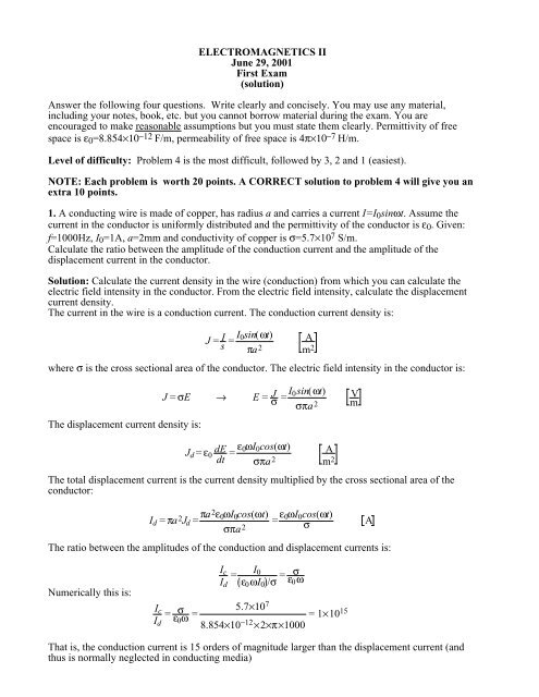
ELECTROMAGNETICS II<br />
June 29, 2001<br />
First Exam<br />
(solution)<br />
Answer the following four questions. Write clearly and concisely. You may use any material,<br />
including your notes, book, etc. but you cannot borrow material during the <strong>exam</strong>. You are<br />
encouraged to make reasonable assumptions but you must state them clearly. Permittivity of free<br />
space is ε 0 =8.854×10 −12 F/m, permeability of free space is 4π×10 −7 H/m.<br />
Level of difficulty: Problem 4 is the most difficult, followed by 3, 2 and 1 (easiest).<br />
NOTE: Each problem is worth 20 points. A CORRECT solution to problem 4 will give you an<br />
extra 10 points.<br />
1. A conducting wire is made of copper, has radius a and carries a current I=I 0 sinωt. Assume the<br />
current in the conductor is uniformly distributed and the permittivity of the conductor is ε 0 . Given:<br />
f=1000Hz, I 0 =1A, a=2mm and conductivity of copper is σ=5.7×10 7 S/m.<br />
Calculate the ratio between the amplitude of the conduction current and the amplitude of the<br />
displacement current in the conductor.<br />
Solution: Calculate the current density in the wire (conduction) from which you can calculate the<br />
electric field intensity in the conductor. From the electric field intensity, calculate the displacement<br />
current density.<br />
The current in the wire is a conduction current. The conduction current density is:<br />
J = I s = I 0sin(ωt)<br />
πa 2<br />
where σ is the cross sectional area of the conductor. The electric field intensity in the conductor is:<br />
A<br />
m 2<br />
The displacement current density is:<br />
J = σE → E = J σ = I 0sin(ωt)<br />
σπa 2<br />
V<br />
m<br />
J d = ε 0 dE<br />
dt = ε 0ωI 0 cos(ωt)<br />
σπa 2<br />
The total displacement current is the current density multiplied by the cross sectional area of the<br />
conductor:<br />
I d = πa 2 J d = πa2 ε 0 ωI 0 cos(ωt)<br />
σπa 2<br />
A<br />
m 2<br />
= ε 0ωI 0 cos(ωt)<br />
σ<br />
The ratio between the amplitudes of the conduction and displacement currents is:<br />
A<br />
Numerically this is:<br />
I c<br />
I d<br />
=<br />
I 0<br />
ε 0 ωI 0 /σ = σ<br />
ε0 ω<br />
I c<br />
=<br />
I σ<br />
d<br />
ε 0 ω = 5.7×10 7<br />
= 1×10 15<br />
8.854×10 −12 ×2×π×1000<br />
That is, the conduction current is 15 orders of magnitude larger than the displacement current (and<br />
thus is normally neglected in conducting media)
2. A method of measuring the permittivity of a flat piece of material is as follows: A transmitter is<br />
placed 0.3m from a conducting wall. A very narrow pulse is transmitted and received in the receiver<br />
after 2 ns. <strong>No</strong>w a flat piece of the dielectric material is placed between the transmitter and the wall<br />
and the signal is received after 2.1 ns. Assume that the only reflections are from the conducting wall<br />
and that the dielectric is a perfect dielectric with permeability of free space. Calculate the relative<br />
permittivity of the dielectric.<br />
Transmitter<br />
d<br />
Transmitter<br />
ε 0 ,µ 0<br />
ε 0 ,µ 0<br />
ε 1 ,µ 0<br />
d 2<br />
d 1<br />
Receiver<br />
Receiver<br />
dielec<br />
tric<br />
<strong>No</strong>te: d 1 +d 2 =d=0.3m.<br />
Solution: The increase in time of propagation to and from the wall is due to the larger permittivity of<br />
the dielectric.<br />
Before the dielectric has been inserted, the phase velocity is:<br />
v p0 = 2d t<br />
= 0.6<br />
2×10 −9 = 3×10⁸ m s<br />
After inserting the dielectric:<br />
or:<br />
t = 2d 2<br />
v p0<br />
+ 2d 1<br />
v p1<br />
→<br />
2d 1<br />
v p1<br />
= t − 2d 2<br />
v p0<br />
2d 1 ε r ε 0 µ 0<br />
1<br />
= 2d 1 ε r<br />
c<br />
= t − 2d 2<br />
v p0<br />
Thus:<br />
ε r =<br />
2d ct −<br />
2d 2 c<br />
=<br />
1 v p0 2d ct − d 2<br />
1 2d 1 d 1<br />
Example: if d 2 =d 1 =0.15m:<br />
ε r = 3×108 ×2.1×10 -9<br />
2×0.15<br />
− 1 = 1.1 → ε r = 1.21<br />
3. A high voltage power line is made of aluminum, has a radius of 20mm and carries a sinusoidal<br />
current of 1000 A at 60 Hz. This current is a conduction current. The conductivity of aluminum is<br />
3.6×10 7 S/m. Assuming the permittivity of aluminum is the same as that of free space, calculate the<br />
displacement current in the power line.
Solution: Calculate the conduction current density in the conductor. From this calculate the electric<br />
field intensity. From the electric field intensity calculate the displacement current density and then<br />
the displacement current.<br />
The conduction current density is the total conduction current divided by the cross sectional area of<br />
the conductor:<br />
J c = I S = Isinωt<br />
πr 2<br />
The electric field intensity in the conductor is:<br />
A<br />
m 2<br />
J c = σE → E = J c<br />
σ = I sinωt<br />
σπr 2<br />
<strong>No</strong>w we can calculate the displacement current density as:<br />
V<br />
m<br />
J d = ε 0<br />
dE<br />
dt<br />
= ε 0<br />
d<br />
dt<br />
I sinωt<br />
σπr 2<br />
= Iε 0ω<br />
cos ωt A<br />
σπr 2<br />
The displacement current is the displacement current density multiplied by cross sectional area:<br />
I d = J d S = Iε 0ωπr 2<br />
σπr 2<br />
m 2<br />
cos ωt = Iε 0ω<br />
σ<br />
cos ωt A<br />
With ω=2π×60=120π, ε 0 =8.854×10 −12 , I=1000 and σ=3.6×10 7 we get:<br />
I d = Iε 0ω<br />
σ<br />
cos ωt = 1000×8.854×10−12 ×120π<br />
3.6×10 7 cos 120πt = 9.27×10 −14 A<br />
<strong>No</strong>te: the very small displacement current compared with the conduction current is the reason we<br />
normally do not consider displacement currents in conductors.<br />
4. A low loss dielectric material is known to have permeability of free space but its conductivity and<br />
permittivity are not knows. Two measurements are performed to determine the permittivity and<br />
conductivity of the material<br />
1. A plane wave is generated so it propagates in the direction indicated in the figure and the time<br />
averaged power density is measured at point (a) and (b). The values obtained are P a and P b .<br />
2. The phase of the plane wave is measured at points (a) and (b). The values obtained are φ a and φ b .<br />
Calculate the permittivity and conductivity of the material if the measurements are performed at a<br />
frequency ω.<br />
d<br />
z<br />
a<br />
φ<br />
P<br />
a<br />
a<br />
µ, ε, σ<br />
b<br />
φ<br />
b P<br />
b
Solution: We can write the attenuation and phase constants from the fact that the material is low<br />
loss, assuming unknown conductivity s and permittivity e. From the power densities at the two<br />
locations we can write in general:<br />
At any point in the material we can write the following:<br />
At z=a we have:<br />
At z=b we have:<br />
<strong>No</strong>w we know that:<br />
P(z) = Pe −2αz e −j2βz<br />
P(z=a) = Pe −2αa e −j2βa<br />
P(z=a) = Pe −2αb e −j2βb<br />
Since P a and P b are given we write:<br />
Pe −2αa = P a and Pe −2αb = P b<br />
or:<br />
Pe −2αa = P a<br />
and<br />
P b<br />
=<br />
P Pe−2αb =<br />
e−2αb<br />
a Pe−2αa e = −2αa e−2αb e 2αa = e<br />
−2α(b − a)<br />
P b<br />
P a<br />
= e −2α(b − a) → ln P b<br />
P a<br />
= −2α(b − a) = −2αd<br />
From this we write:<br />
α = − 1 2d ln P b<br />
P a<br />
= 1 2d ln P a<br />
P b<br />
The attenuation constant for low loss dielectrics is also equal to:<br />
Thus the first relation we have is:<br />
α = σ 2<br />
µ 0ε<br />
1<br />
d ln P a<br />
P b<br />
= σ µ 0<br />
ε<br />
In this relation the unknowns are s and e. We need another relation and this is found from the phase.<br />
We write:<br />
The change in phase may be written as:<br />
φ a = βa, φ b = βb<br />
or:<br />
φ b − φ a = βb − βa = β(b − a) = βd<br />
For a low loss dielectric we have:<br />
Thus:<br />
φ b − φ a = βd<br />
β = ω µ 0 ε
φ b − φ a = ωd µ 0 ε<br />
In this relation the only unknown is e so we can write:<br />
ε = φ b − φ a<br />
2<br />
ω 2 d 2 µ 0<br />
Substituting this into the first relation, we write:<br />
σ = 1 ε<br />
d µ<br />
ln P a<br />
= 0 P 1 φ b − φ<br />
2 a<br />
ln P a<br />
b d ω 2 d 2 µ<br />
2 0<br />
P b<br />
Thus, the conductivity and permittivity of the material are:<br />
= 1 d<br />
φ b − φ a<br />
ωdµ 0<br />
ln P a<br />
P b<br />
σ = 1 d<br />
φ b − φ a<br />
ωdµ 0<br />
ln P a<br />
P b<br />
and ε = φ b − φ a<br />
2<br />
ω 2 d 2 µ 0