RAiO RA8806 - Display Future
RAiO RA8806 - Display Future
RAiO RA8806 - Display Future

Create successful ePaper yourself
Turn your PDF publications into a flip-book with our unique Google optimized e-Paper software.
Version 1.3<br />
<strong>RA8806</strong><br />
Two Layers Character/Graphic LCD Controller<br />
6-9 PWM<br />
<strong>RA8806</strong> provide a set of programmable PWM (Pulse Width Modulation) for LCD contrast adjustment.<br />
The PWM frequency and duty can be set by register. And the driving capability of PWM output pin is<br />
larger than other output pin, about 4 multiples of normal output. Besides, if the PWM function is disable,<br />
it can use as normal IO signal. The relative function setting please refers to the table below.<br />
Table 6-21<br />
Reg. Bit_Num Description Reference<br />
PCR<br />
Bit 7 PWM function enable<br />
Bit [3:0] Clock source divide ratio select<br />
REG[D0h]<br />
PDCR Bit [7:0] PWM Duty Cycle Select REG[D1h]<br />
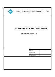
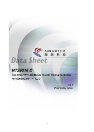
The following are two examples for the PWM output (pin “PWM_OUT”):<br />
T PWM<br />
T H<br />
T L<br />
Example-1:<br />
System Clock = 10Mhz,<br />
Register PCR Bit[3:0] = 0001b Clock Source = 10MHz/2 = 5MHz<br />
T PWM = 256*(1/5MHz) = 51.2µs<br />
Register PDCR Bit[7:0] = 0Fh <br />
T H = 16*(1/5MHz) = 3.2µs<br />
T L = (256-16) * (1/ 5MHz) = 48µs<br />
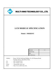
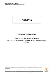
T PWM<br />
T H<br />
T L<br />
Example-2:<br />
System Clock = 10Mhz,<br />
Register PCR Bit[3:0] = 0010b Clock Source = 10MHz/4 = 2.5MHz<br />
T PWM = 256*(1/2.5MHz) = 102.4 µs<br />
Register PDCR Bit[7:0] = 7Fh <br />
T H = 128*(1/2.5MHz) = 51.2µs<br />
T L = (256-128) * (1/ 2.5MHz) = 51.2µs<br />
Figure 6-37 : PWM_OUT Pulse<br />
<strong>RAiO</strong> TECHNOLOGY INC. 68/193 www.raio.com.tw