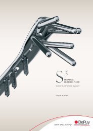
S3™ Proximal Humerus Plating System Surgical Technique - Biomet
S3™ Proximal Humerus Plating System Surgical Technique - Biomet
S3™ Proximal Humerus Plating System Surgical Technique - Biomet
You also want an ePaper? Increase the reach of your titles
YUMPU automatically turns print PDFs into web optimized ePapers that Google loves.
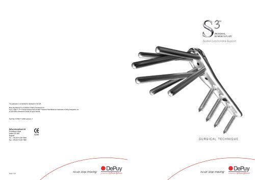
PROXIMAL<br />
HUMERUS PLATE<br />
Spatial Subchondral Support<br />
This publication is not intended for distribution in the USA.<br />
Never Stop Moving is a trademark of DePuy International Ltd.<br />
F.A.S.T. Guide, S 3 <strong>Proximal</strong> <strong>Humerus</strong> Plate and SNP Anatomic Plate Module are trademarks of DePuy Orthopaedics, Inc.<br />
© 2009 DePuy International Limited. All rights reserved.<br />
Cat No: 0709-11-000 version 1<br />
DePuy International Ltd<br />
St Anthony’s Road<br />
Leeds LS11 8DT<br />
England<br />
Tel: +44 (0)113 387 7800<br />
Fax: +44 (0)113 387 7890<br />
0086<br />
SURGICAL TECHNIQUE<br />
Issued: 11/09
<strong>Surgical</strong> <strong>Technique</strong> Guide<br />
Designed To...<br />
S 3 <strong>Proximal</strong> <strong>Humerus</strong> Plate<br />
Based on our experience in distal radius fracture management we’ve designed the new <strong>Proximal</strong> Humeral Plate.<br />
Simplified Soft Tissue Fixation<br />
• Uniquely designed suture holes allow tuberosity repairs after humeral head fixation<br />
• Suture holes are designed to accommodate multiple passes for extensive soft tissue fixation<br />
F.A.S.T. Guide Technology<br />
• Pre-loaded single use disposable drill guides<br />
• No intraoperative assembly required resulting in significant time savings<br />
• F.A.S.T. Guide are colour coded for easy plate identification: Red = Right, Lime = Left<br />
Help Restore the Natural Anatomy<br />
• Precisely contoured plates are designed to<br />
mirror the complex shape of the<br />
proximal humerus<br />
• The S 3 <strong>Proximal</strong> <strong>Humerus</strong> Plate is designed<br />
to act as a reduction template to help restore<br />
the natural anatomy<br />
• Multiple 4.0 mm subchondral support pegs<br />
and screws maintain fracture reduction<br />
Minimise Subacromial Impingement<br />
• The S 3 <strong>Proximal</strong> <strong>Humerus</strong> Plate is designed<br />
to be positioned approximately 3.0 cm distal to<br />
the greater tuberosity preventing<br />
subacromial impingement<br />
• Anatomically contoured under surface aids in<br />
restoring humeral head rotation<br />
Provide a Strong and Stable Construct<br />
• Precise fixed angle peg distribution provides<br />
spatial subchondral support to resist varus<br />
forces throughout the full range of motion<br />
• <strong>Proximal</strong> and distal locking screws and pegs<br />
ensure a strong interface for a secure and<br />
stable construct<br />
• Blunt tipped subchondral support pegs<br />
provide improved stability while preventing<br />
protrusion through the articular surface<br />
Achieve Predictable and<br />
Reproducible Results<br />
• Central guiding K-Wire provides visual<br />
confirmation for plate positioning<br />
• Manually inserted blunt-tipped drill bits provide<br />
protection against the potential perforation of<br />
the articular surface<br />
• Predetermined peg trajectories ensure a<br />
consistent spatial distribution within the<br />
humeral head<br />
2 3
<strong>Surgical</strong> <strong>Technique</strong><br />
<strong>Surgical</strong> <strong>Technique</strong><br />
Step 1: Procedure Mapping<br />
• Exposure: deltopectoral<br />
• Identify: coracoid, acromium and<br />
deltoid insertion<br />
Step 4: Exposure<br />
• The exposure is through a 12 ‐ 14 cm incision<br />
• Identify and retract the cephalic vein<br />
• Develop the interval between the pectoralis<br />
and deltoid<br />
• Extend incision line distal from coracoid<br />
• Self retaining retractors are useful for exposure<br />
Tips: during the exposure, the 2.8 mm drill<br />
bit can be loaded in preparation for plate<br />
application.<br />
Step 2: Patient Positioning<br />
• Sterile Mayo stand assists during dissection<br />
Tips: the procedure can be performed in the<br />
beach chair position or supine as per surgeon’s<br />
discretion.<br />
Step 5: Pectoralis Incision and<br />
Identification of the Biceps Tendon<br />
• Gently retract the coracobrachialis medially<br />
• Find the pectoralis insertion at the floor of the<br />
deltoid pectoralis interval<br />
• Release the proximal third of the pectoralis<br />
tendon to expose the biceps<br />
Step 3: Acquire Initial Images<br />
• Examine the fracture under fluoroscopy<br />
• Internal rotation, external rotation and<br />
sometimes axillary views are necessary<br />
Step 6: Complete Exposure<br />
• Develop the subacromial space and mobilise<br />
the proximal deltoid<br />
Tips: use of a large, blunt humeral head<br />
depressor can facilitate exposure.<br />
4 5
<strong>Surgical</strong> <strong>Technique</strong><br />
<strong>Surgical</strong> <strong>Technique</strong><br />
Step 7: Fracture Debridement<br />
• Debride the fracture<br />
Step 10: Apply Bone Graft<br />
• To facilitate healing, bone graft should<br />
be considered<br />
Step 8: Fracture Reduction<br />
• After debridement, the fracture is reduced by<br />
traction and indirect manipulation<br />
Tips: remove the Mayo table to<br />
facilitate reduction.<br />
Step 11: Determine the Proper<br />
Plate Position<br />
• Select the appropriate side plate (left or right)<br />
• Choose the appropriate length (3,4,6,8,11 or<br />
14 hole)<br />
• Fix the shaft of the plate using a 3.8 mm<br />
cortical screw through the slotted hole<br />
Tips: If using prepacked sterile implants, S3<br />
trial templates can be used to confirm the<br />
required plate size.<br />
Apply the plate 2 cm to 2.5 cm distal to the<br />
insertion of the supraspinatus, the anterior<br />
border of the plate should be immediately<br />
lateral to the bicipital groove.<br />
Step 9: Tuberosity Repair<br />
• In the case of severe comminution, suturing<br />
the rotator cuff together will help reduce<br />
the tuberosities<br />
After plate positioning a 2.0 mm guide wire will<br />
need to be loaded in the wire driver.<br />
Step 12: Drill Central Guide Wire<br />
• Drill the 2.0 mm guide wire through the central<br />
hole on the proximal portion of the plate.<br />
Advance slowly and verify its trajectory<br />
under fluoroscopy<br />
6 7
<strong>Surgical</strong> <strong>Technique</strong><br />
<strong>Surgical</strong> <strong>Technique</strong><br />
Step 13: Verify Central Guide<br />
Wire Placement<br />
• Place the guide wire in the centre of the<br />
humeral head<br />
• This plate position will reduce the risk of<br />
subacromial impingement<br />
Step 15: Manually Drill for Subchondral<br />
Support Pegs<br />
• With the 4.0 mm drill attached to the driver<br />
handle, advance the drill, through the drill<br />
guide until resistance from subchondral bone<br />
is felt<br />
• This will ensure that the peg engages<br />
subchondral bone for optimal fixation<br />
Tips: when drilling for smooth pegs use FDB40L<br />
(Drill Bit Fast 4.0 mm Long).<br />
When drilling for partially threaded pegs use<br />
FDS40 (Drill Bit Fast 4.0 mm Step).<br />
Step 14: Drill Cortex Through<br />
F.A.S.T. Guide<br />
• Using the short 4.0mm drill (FDB40S), drill<br />
through the F.A.S.T. Guide and perforate<br />
the cortex<br />
• This drill has a stop that will only<br />
allow it to penetrate the<br />
near cortex<br />
• If re-drilling is required after F.A.S.T. Guide<br />
removal, thread the drill guide (DRGSH) into<br />
the desired peg hole and drill on power using<br />
DB40S (Drill Bit Short 4.0 mm)<br />
Tips: bending the central guide wire and<br />
rotating it out of the way will ease the<br />
attachment of the drill guide to the plate.<br />
Other K-Wire holes can be used to provisionally<br />
fix the plate to the bone.<br />
Step 16: Verify Drill Depth<br />
• Once resistance is felt, fluoro imaging should<br />
verify that the tip of the manual drill is close to<br />
subchondral bone<br />
• Care should be taken not to penetrate<br />
subchondral bone<br />
Tips: the depth gauges have a bias built in that<br />
will reduce the measured depth by 2.5 mm. If<br />
peg to subchondral bone contact is desired,<br />
add 2.5 mm to the depth gauge.<br />
Depths can be Gauged from the<br />
manual drill or the sleeveless depth<br />
gauge. Both can be read through<br />
either the F.A.S.T. Guide or through<br />
the drill guide, using the appropriate<br />
calibrated scale.<br />
8 9
<strong>Surgical</strong> <strong>Technique</strong><br />
<strong>Surgical</strong> <strong>Technique</strong><br />
Step 17: Attach Tuberosities to Plate<br />
• Using 20 gauge, monofilament stainless wire,<br />
secure the tuberosities to the plate by passing<br />
the needles close to the insertion of the tendon<br />
and then through to side, front or top loading<br />
wire attachment points (see insert)<br />
Step 19: Final Verification<br />
• Evaluate the humerus under fluoroscopy to<br />
assess the reduction and to confirm<br />
proper positioning<br />
• Twist the wire until appropriate tension<br />
is reached<br />
Step 18: Fix Remaining Screws in Plate<br />
• The shaft of the plate can be fixed with either<br />
90˚ locking screws or multidirectional<br />
cortical screws<br />
Step 20: Function<br />
• The S 3 <strong>Proximal</strong> <strong>Humerus</strong> Plate is designed<br />
to provide the greatest patient function and the<br />
lowest risk of subacromial impingement<br />
• Using the appropriate end of the tissue<br />
protector, drill to the correct depth (far cortex)<br />
and measure with the barrel depth gauge<br />
• Multiple divergent blunt pegs provide optimum<br />
subchondral support<br />
• Use a set screw for each 90˚ screw to lock it<br />
into place<br />
• Do not use a set screw when using<br />
multidirectional screws<br />
Tips: an alternate approach is to apply the wire<br />
tension bands to the plate prior to placing the<br />
subchondral support pegs. This may aid in the<br />
reduction.<br />
10 11
Peg and Screw Options<br />
S 3 <strong>Proximal</strong> <strong>Humerus</strong> Plate Shoulder Fixation <strong>System</strong><br />
Description<br />
1 Smooth Pegs, Locking<br />
2 Threaded Pegs, Locking<br />
3 90˚ Cortical Screws,<br />
Non-locking<br />
4 Multi-directional Cortical<br />
Screws, Non-Locking<br />
5 90˚ Locking Set Screw<br />
Provides spatial subchondral support<br />
Help to capture and lag the humeral head<br />
Provide bi-cortical fixation while locking to<br />
the plate using the NL-SS sets crews<br />
Provide multi-directional fixation when used<br />
through the oblong hole<br />
Secures the 90˚ lock distal screws to the plate<br />
1<br />
STP Series<br />
4 MD Series 5 NL-SS Series<br />
2 STPT Series 3 NL Series<br />
Important:<br />
This <strong>Surgical</strong> <strong>Technique</strong> guide does not include all of the information necessary for the selection and use of this device. Please<br />
refer to instructions for use (I.F.U.) and product labelling for all necessary information.<br />
Indications:<br />
The S 3 <strong>Proximal</strong> <strong>Humerus</strong> Plate is indicated for fractures and fracture dislocations, osteotomies, and non-unions of the<br />
proximal humerus.<br />
Plate Options<br />
Description<br />
head Width x Shaft Width x Overall Length<br />
STP, STPT Series available in 20 mm - 65 mm Lengths (2.5 mm Steps)<br />
NL, MD Series available in 20 mm - 38 mm Lengths (2 mm Steps)<br />
Contraindications:<br />
If any of the following are suspected, tests are to be performed prior to implantation. Active or latent infection. Sepsis. Insufficient<br />
quantity or quality of bone and/or soft tissue. Material sensitivity. Patients who are unwilling or incapable of following post operative<br />
care instructions.<br />
Warning and Precautions:<br />
If any of the following are suspected, tests are to be performed prior to implantation:<br />
6<br />
7<br />
8<br />
9<br />
10<br />
11<br />
S 3 <strong>Proximal</strong> <strong>Humerus</strong> Plate<br />
S 3 <strong>Proximal</strong> <strong>Humerus</strong> Plate<br />
S 3 <strong>Proximal</strong> <strong>Humerus</strong> Plate<br />
S 3 <strong>Proximal</strong> <strong>Humerus</strong> Plate<br />
S 3 <strong>Proximal</strong> <strong>Humerus</strong> Plate<br />
S 3 <strong>Proximal</strong> <strong>Humerus</strong> Plate<br />
16.0 mm x 11.8 mm x 70.0 mm<br />
17.0 mm x 12.3 mm x 87.1 mm<br />
17.0 mm x 17.0 mm x 110 mm<br />
17.0 mm x 17.0 mm x 150 mm<br />
17.0 mm x 17.0 mm x 195 mm<br />
17.0 mm x 17.0 mm x 246 mm<br />
6<br />
7<br />
8<br />
3 hole<br />
4 hole<br />
6 hole<br />
• Active or latent infection<br />
• Insufficient quantity or quality of bone and/or soft tissue<br />
• Material sensitivity<br />
9<br />
8 hole<br />
• Sepsis<br />
10<br />
11<br />
11 hole<br />
14 hole<br />
• Patients who are unwilling or incapable of following post operative care instructions<br />
Warnings and Precautions:<br />
An implant must never be reused. Previous stresses may have created imperfections that can potentially lead to device failure.<br />
Instrumentation must be inspected for wear or damage prior to usage. Protect implants against scratching or nicking. Such stress<br />
concentration can lead to failure.<br />
Adverse Effects:<br />
Potential for these devices failing as a result of loose fixation and/or loosening, caused by:<br />
• Mechanical Stress<br />
• Excessive activity<br />
• Load bearing particularly when the implants experience increased loads due to a delayed union, nonunion, or<br />
incomplete healing<br />
12 13
Ordering Information<br />
Ordering Information<br />
Instruments<br />
Description<br />
Order Code<br />
Implants<br />
Description<br />
Non-Sterile Code<br />
Sterile Code<br />
Guide Soft Tissue Shoulder<br />
Depth Gauge Shoulder<br />
F.A.S.T Shoulder Depth Gauge Stepped<br />
2.0 mm Square Driver Insert<br />
4.0 mm Drill Guide Shoulder<br />
Handle Mini Quick Connect<br />
Cannulated Ratcheting Handle<br />
Quick Couple Handle<br />
F.A.S.T Peg Driver 4.0 mm<br />
S3 Trial 3/4 Hole Left<br />
S3 Trial 6 Hole Left<br />
S3 Trial 8 Hole Left<br />
S3 Trial 11/14 Hole Left<br />
S3 Trial 3/4 Hole Right<br />
S3 Trial 6 Hole Right<br />
S3 Trial 8 Hole Right<br />
S3 Trial 11/14 Hole Right<br />
Instrument Cases<br />
Description<br />
Sterile Instrument Case<br />
Non-Sterile Instrument Case<br />
Disposables<br />
Description<br />
2.8 mm Drill for Distal Screw<br />
4.0 mm F.A.S.T Guide Long Drill<br />
4.0 mm F.A.S.T Guide Short Drill<br />
4.0 mm F.A.S.T Guide Drill<br />
K-wire, 2.0 mm<br />
Implants<br />
Description<br />
3.8 x 20.0 mm Multidirectional Screw<br />
3.8 x 22.0 mm Multidirectional Screw<br />
3.8 x 24.0 mm Multidirectional Screw<br />
3.8 x 26.0 mm Multidirectional Screw<br />
3.8 x 28.0 mm Multidirectional Screw<br />
3.8 x 30.0 mm Multidirectional Screw<br />
3.8 x 32.0 mm Multidirectional Screw<br />
3.8 x 34.0 mm Multidirectional Screw<br />
3.8 x 36.0 mm Multidirectional Screw<br />
3.8 x 38.0 mm Multidirectional Screw<br />
3.8 x 20.0 mm 90º Locking Screw<br />
3.8 x 22.0 mm 90º Locking Screw<br />
3.8 x 24.0 mm 90º Locking Screw<br />
3.8 x 26.0 mm 90º Locking Screw<br />
3.8 x 28.0 mm 90º Locking Screw<br />
3.8 x 30.0 mm 90º Locking Screw<br />
3.8 x 32.0 mm 90º Locking Screw<br />
3.8 x 34.0 mm 90º Locking Screw<br />
3.8 x 36.0 mm 90º Locking Screw<br />
3.8 x 38.0 mm 90º Locking Screw<br />
SSTG<br />
SBDG<br />
FSDGS<br />
SDI<br />
DRGSH<br />
MQC<br />
8261-66-000<br />
QCH<br />
FPD40<br />
2312-03-503<br />
2312-03-506<br />
2312-03-508<br />
2312-03-514<br />
2312-03-603<br />
2312-03-606<br />
2312-03-608<br />
2312-03-614<br />
Order Code<br />
2312-03-500<br />
PHT<br />
Non-Sterile Code<br />
MD20<br />
MD22<br />
MD24<br />
MD26<br />
MD28<br />
MD30<br />
MD32<br />
MD34<br />
MD36<br />
MD38<br />
NL20<br />
NL22<br />
NL24<br />
NL26<br />
NL28<br />
NL30<br />
NL32<br />
NL34<br />
NL36<br />
NL38<br />
Order Code<br />
2312-01-309<br />
2312-01-306<br />
2312-01-307<br />
2312-01-308<br />
2312-01-310<br />
Sterile Code<br />
8575-38-020<br />
8575-38-022<br />
8575-38-024<br />
8575-38-026<br />
8575-38-028<br />
8575-38-030<br />
8575-38-032<br />
8575-38-034<br />
8575-38-036<br />
8575-38-038<br />
8575-90-020<br />
8575-90-022<br />
8575-90-024<br />
8575-90-026<br />
8575-90-028<br />
8575-90-030<br />
8575-90-032<br />
8575-90-034<br />
8575-90-036<br />
8575-90-038<br />
S3 Shoulder Plate 3 Hole Left<br />
S3 Shoulder Plate 4 Hole Left<br />
S3 Shoulder Plate 6 Hole Left<br />
S3 Shoulder Plate 8 Hole Left<br />
S3 Shoulder Plate 11 Hole Left<br />
S3 Shoulder Plate 14 Hole Left<br />
S3 Shoulder Plate 3 Hole Right<br />
S3 Shoulder Plate 4 Hole Right<br />
S3 Shoulder Plate 6 Hole Right<br />
S3 Shoulder Plate 8 Hole Right<br />
S3 Shoulder Plate 11 Hole Right<br />
S3 Shoulder Plate 14 Hole Right<br />
4.0 x 20.0 mm Standard Peg<br />
4.0 x 25.0 mm Standard Peg<br />
4.0 x 30.0 mm Standard Peg<br />
4.0 x 32.0 mm Standard Peg<br />
4.0 x 35.0 mm Standard Peg<br />
4.0 x 37.5 mm Standard Peg<br />
4.0 x 40.0 mm Standard Peg<br />
4.0 x 42.5 mm Standard Peg<br />
4.0 x 45.0 mm Standard Peg<br />
4.0 x 47.5 mm Standard Peg<br />
4.0 x 50.0 mm Standard Peg<br />
4.0 x 52.5 mm Standard Peg<br />
4.0 x 55.0 mm Standard Peg<br />
4.0 x 57.5 mm Standard Peg<br />
4.0 x 60.0 mm Standard Peg<br />
4.0 x 62.5 mm Standard Peg<br />
4.0 x 65.0 mm Standard Peg<br />
4.0 x 20.0 mm Threaded Peg<br />
4.0 x 25.0 mm Threaded Peg<br />
4.0 x 30.0 mm Threaded Peg<br />
4.0 x 32.5 mm Threaded Peg<br />
4.0 x 35.0 mm Threaded Peg<br />
4.0 x 37.5 mm Threaded Peg<br />
4.0 x 40.0 mm Threaded Peg<br />
4.0 x 42.5 mm Threaded Peg<br />
4.0 x 45.0 mm Threaded Peg<br />
4.0 x 47.5 mm Threaded Peg<br />
4.0 x 50.0 mm Threaded Peg<br />
4.0 x 52.5 mm Threaded Peg<br />
4.0 x 55.0 mm Threaded Peg<br />
4.0 x 57.5 mm Threaded Peg<br />
4.0 x 60.0 mm Threaded Peg<br />
4.0 x 62.5 mm Threaded Peg<br />
4.0 x 65.0 mm Threaded Peg<br />
SSPL3<br />
SSPL4<br />
SSPL6<br />
SSPL8<br />
SSPL11<br />
SSPL14<br />
SSPR3<br />
SSPR4<br />
SSPR6<br />
SSPR8<br />
SSPR11<br />
SSPR14<br />
STP20<br />
STP25<br />
STP30<br />
STP325<br />
STP35<br />
STP375<br />
STP40<br />
STP425<br />
STP45<br />
STP475<br />
STP50<br />
STP525<br />
STP55<br />
STP575<br />
STP60<br />
STP625<br />
STP65<br />
STPT20<br />
STPT25<br />
STPT30<br />
STPT325<br />
STPT35<br />
STPT375<br />
STPT40<br />
STPT425<br />
STPT45<br />
STPT475<br />
STPT50<br />
STPT525<br />
STPT55<br />
STPT575<br />
STPT60<br />
STPT625<br />
STPT65<br />
8572-01-003<br />
8572-01-004<br />
8572-01-006<br />
8572-01-008<br />
8572-01-011<br />
8572-01-014<br />
8572-02-003<br />
8572-02-004<br />
8572-02-006<br />
8572-02-008<br />
8572-02-011<br />
8572-02-014<br />
8570-40-200<br />
8570-40-250<br />
8570-40-300<br />
8570-40-325<br />
8570-40-350<br />
8570-40-374<br />
8570-40-400<br />
8570-40-425<br />
8570-40-450<br />
8570-40-475<br />
8570-40-500<br />
8570-40-525<br />
8570-40-550<br />
8570-40-575<br />
8570-40-600<br />
8570-40-625<br />
8570-40-650<br />
8571-40-200<br />
8571-40-250<br />
8571-40-300<br />
8571-40-325<br />
8571-40-350<br />
8571-40-374<br />
8571-40-400<br />
8571-40-425<br />
8571-40-450<br />
8571-40-475<br />
8571-40-500<br />
8571-40-525<br />
8571-40-550<br />
8571-40-575<br />
8571-40-600<br />
8571-40-625<br />
8571-40-650<br />
90º Locking Screw<br />
NLSS<br />
8575-90-000<br />
14 15


