Phased Array Using the Sequential Rotation Principle - Empire
Phased Array Using the Sequential Rotation Principle - Empire
Phased Array Using the Sequential Rotation Principle - Empire

Create successful ePaper yourself
Turn your PDF publications into a flip-book with our unique Google optimized e-Paper software.
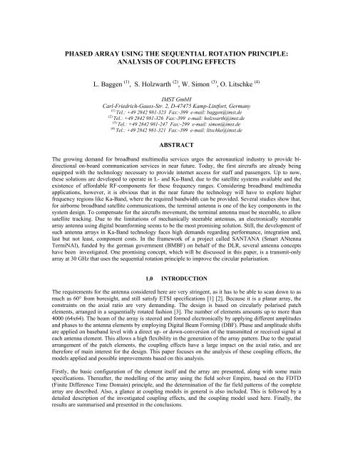
PHASED ARRAY USING THE SEQUENTIAL ROTATION PRINCIPLE:<br />
ANALYSIS OF COUPLING EFFECTS<br />
L. Baggen (1) , S. Holzwarth (2) , W. Simon (3) , O. Litschke (4)<br />
IMST GmbH<br />
Carl-Friedrich-Gauss-Str. 2, D-47475 Kamp-Lintfort, Germany<br />
(1)<br />
Tel.: +49 2842 981-323 Fax:-399 e-mail: baggen@imst.de<br />
(2)<br />
Tel.: +49 2842 981-326 Fax:-399 e-mail: holzwarth@imst.de<br />
(3)<br />
Tel.: +49 2842 981-247 Fax:-299 e-mail: simon@imst.de<br />
(4)<br />
Tel.: +49 2842 981-321 Fax:-399 e-mail: litschke@imst.de<br />
ABSTRACT<br />
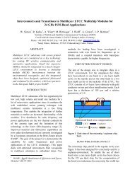
The growing demand for broadband multimedia services urges <strong>the</strong> aeronautical industry to provide bidirectional<br />
on-board communication services in near future. Today, <strong>the</strong> first aircrafts are already being<br />
equipped with <strong>the</strong> technology necessary to provide internet access for staff and passengers. Up to now,<br />
<strong>the</strong>se solutions are developed to operate in L- and Ku-Band, due to <strong>the</strong> satellite systems available and <strong>the</strong><br />
existence of affordable RF-components for <strong>the</strong>se frequency ranges. Considering broadband multimedia<br />
applications, however, it is obvious that in <strong>the</strong> near future <strong>the</strong> technology will have to explore higher<br />
frequency regions like Ka-Band, where <strong>the</strong> required bandwidth can be provided. Several studies show that,<br />
for airborne broadband satellite communications, <strong>the</strong> terminal antenna is one of <strong>the</strong> key components in <strong>the</strong><br />
system design. To compensate for <strong>the</strong> aircrafts movement, <strong>the</strong> terminal antenna must be steerable, to allow<br />
satellite tracking. Due to <strong>the</strong> limitations of mechanically steerable antennas, an electronically steerable<br />
array antenna using digital beamforming seems to be <strong>the</strong> most promising solution. Still, <strong>the</strong> development of<br />
such antenna arrays in Ka-Band technology faces high demands regarding performance, integration and,<br />
last but not least, component costs. In <strong>the</strong> framework of a project called SANTANA (Smart ANtenna<br />
TermiNAl), funded by <strong>the</strong> german government (BMBF) on behalf of <strong>the</strong> DLR, several antenna concepts<br />
have been investigated. One promising concept, which will be discussed in this paper, is a transmit-only<br />
array at 30 GHz that uses <strong>the</strong> sequential rotation principle to improve <strong>the</strong> circular polarisation.<br />
1.0 INTRODUCTION<br />
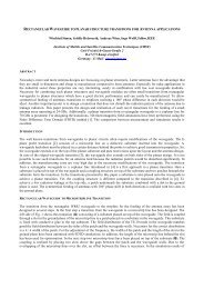
The requirements for <strong>the</strong> antenna considered here are very stringent, as it has to be able to scan down to as<br />
much as 60° from boresight, and still satisfy ETSI specifications [1] [2]. Because it is a planar array, <strong>the</strong><br />
constraints on <strong>the</strong> axial ratio are very demanding. The design is based on circularly polarised patch<br />
elements, arranged in a sequentially rotated fashion [3]. The number of elements amounts up to more than<br />
4000 (64x64). The beam of <strong>the</strong> array is steered and formed electronically by applying different amplitudes<br />
and phases to <strong>the</strong> antenna elements by employing Digital Beam Forming (DBF). Phase and amplitude shifts<br />
are applied on baseband level with a direct up- or down-conversion of <strong>the</strong> transmitted or received signal at<br />
each antenna element. This allows a high flexibility in <strong>the</strong> generation of <strong>the</strong> array pattern. Due to <strong>the</strong> spatial<br />
arrangement of <strong>the</strong> patch elements, <strong>the</strong> coupling effects have a large impact on <strong>the</strong> axial ratio, and are<br />
<strong>the</strong>refore of main interest for <strong>the</strong> design. This paper focuses on <strong>the</strong> analysis of <strong>the</strong>se coupling effects, <strong>the</strong><br />
models applied and possible improvements based on this analysis.<br />
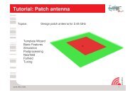
Firstly, <strong>the</strong> basic configuration of <strong>the</strong> element itself and <strong>the</strong> array are presented, along with some main<br />
specifications. Thereafter, <strong>the</strong> modelling of <strong>the</strong> array using <strong>the</strong> field solver <strong>Empire</strong>, based on <strong>the</strong> FDTD<br />
(Finite Difference Time Domain) principle, and <strong>the</strong> determination of <strong>the</strong> far field patterns of <strong>the</strong> complete<br />
array are described. Also, a glance at coupling models in general is also included. This is followed by a<br />
detailed description of <strong>the</strong> investigated coupling effects, and <strong>the</strong> coupling model used here. Finally, <strong>the</strong><br />
results are summarised and presented in <strong>the</strong> conclusions.
2.0 BASIC ELEMENT & CONFIGURATION<br />
The basic antenna element consists of a circularly polarised patch element, which is fed by a circular<br />
waveguide via an elliptical slot. All patches of <strong>the</strong> array have a square shape, and can each be separately<br />
steered in amplitude and phase. The schematic is displayed in figure 1.<br />
Patch, circularly polarised<br />
Substrate<br />
Slot<br />
Circular waveguide<br />
Figure 1. Overview of <strong>the</strong> basic antenna element.<br />
As mentioned previously, <strong>the</strong>se elements will be sequentially rotated as indicated in figure 2, in order to<br />
improve <strong>the</strong> axial ratio. The patches are not only rotated spatially 90° with respect to each o<strong>the</strong>r, but also<br />
fed with a 90° phase shift. Normally, <strong>the</strong> sequential rotation principle is used to generate circular<br />
polarisation when using linearly polarised patch elements [3]. Yet, <strong>the</strong> use of sequentially rotated circularly<br />
polarised elements enhances <strong>the</strong> polarisation behaviour of <strong>the</strong> array [4], and bring <strong>the</strong> design one step<br />
fur<strong>the</strong>r towards fulfilling <strong>the</strong> stringent requirements. The array will be composed of approximately 4000 of<br />
such elements, arranged in subgroups of 4 rotated elements. The frequency bandwidth is 29.5-30 GHz, and<br />
<strong>the</strong> element spacing is approximately 5 mm (about half a wavelength at 29.7 GHz). The maximum scan<br />
angle is 60° with respect to boresight. Because <strong>the</strong> bandwidth is an uncritical parameter in <strong>the</strong> design, all<br />
radiation patterns given in this paper will be determined for <strong>the</strong> centre frequency of 29.7 GHz.<br />
270°<br />
180°<br />
270°<br />
180°<br />
270°<br />
180°<br />
0° 90°<br />
0° 90°<br />
0° 90°<br />
270°<br />
180°<br />
270°<br />
180°<br />
Basic group<br />
0° 90°<br />
0° 90°<br />
Figure 2. Patches arranged according to <strong>the</strong> sequential rotation principle.
3.0 BASIC MODELLING OF THE ARRAY<br />
The radiation patterns and <strong>the</strong> inp ut return loss are determined with <strong>the</strong> help of <strong>the</strong> FDTD-field solver<br />
EMPIRE. It is impossible to model a large number of such complex elements due to practical restrictions as<br />
available memory and computation time, which limit <strong>the</strong> size of <strong>the</strong> array model. Moreover, beam steering,<br />
which is one of <strong>the</strong> key points of <strong>the</strong> design, is difficult to implement with FDTD-modelling. Thus, <strong>the</strong><br />
following approach has been adopted: only a small number of elements are modelled, yet <strong>the</strong> most<br />
significant coupling effects, also called “first order” coupling effects, are included. Normally, this involves<br />
embedding <strong>the</strong> active element in <strong>the</strong> array structure, and taking only its direct neighbours into account, as<br />
displayed in figure 3a. These neighbours are considered as passive components, and are terminated with an<br />
ideal impedance (in <strong>the</strong> model, PML-walls).<br />
The complete radiating structure (active and passive patches) is enclosed by a box that registers <strong>the</strong> near<br />
fields, as shown in figure 3a. In order to obtain <strong>the</strong> far fields, <strong>the</strong> E- and H-fields on <strong>the</strong> walls of this box<br />
are transformed, using image <strong>the</strong>ory and <strong>the</strong> equivalence principle [5]. The far field pattern of this<br />
embedded element is multiplied by <strong>the</strong> appropriate array factor, in order to arrive at <strong>the</strong> far field pattern of<br />
<strong>the</strong> complete array. This is also called <strong>the</strong> C-approach [6]. By adding a phase shift for each element, <strong>the</strong><br />
influence of coupling on <strong>the</strong> scan performance can also be easily investigated.<br />
4.0 COUPLING EFFECTS<br />
The sequential rotated configuration implies that <strong>the</strong> patches are arranged in groups of 4 elements, which<br />
are each situated spatially in a 90° shifted sequence (see also figure 2). First simulations have shown that<br />
this spatial orientation has a major impact on <strong>the</strong> determination of <strong>the</strong> far field patterns. Thus, modelling<br />
only one active element surrounded by passive elements does not suffice. The basic model, as presented in<br />
figure 3a, has to be extended to account for <strong>the</strong> special configuration. Therefore, <strong>the</strong> basic group adopted<br />
here consists of a total of 16 elements: a group of 4 elements sequentially arranged, surrounded by a ring of<br />
passive neighbours as depicted in figure 3b. This model is still quite good to handle with respect to required<br />
simulation time and available CPU-memory. For each of <strong>the</strong> 4 patches in <strong>the</strong> group <strong>the</strong> far field is<br />
determined, considering 1 active patch, and <strong>the</strong> remaining 15 as passive elements. Afterwards, <strong>the</strong><br />
sequential 90° phase shift is added, and <strong>the</strong> 4 far field patterns are superimposed, with <strong>the</strong> phase centre<br />
located in <strong>the</strong> centre of <strong>the</strong> 4 patches. The far field of <strong>the</strong> phased array is calculated by multiplying <strong>the</strong><br />
group pattern, derived from simulation, by <strong>the</strong> appropriate array factor (based on superimposing 2x2 groups<br />
of patches). This approach still offers <strong>the</strong> possibility to steer each patch with a variable amplitude and phase<br />
shift, thus enabling investigation of <strong>the</strong> scanning behaviour and tapering.<br />
180° 270° 180°<br />
90°<br />
0°<br />
90°<br />
0°<br />
90° 0°<br />
90°<br />
180°<br />
270°<br />
180°<br />
270°<br />
180° 270°<br />
180°<br />
90°<br />
0° 90°<br />
0°<br />
180°<br />
270°<br />
180°<br />
270°<br />
Figure 3. Coupling: general first order model (a), extended sequential rotated model (b), active patches in red.
An interesting aspect that was noticed during <strong>the</strong> investigations is that <strong>the</strong> properties of <strong>the</strong> circularly<br />
polarised patch change very quickly due to coupling. The stand alone patch (without any neighbouring<br />
patches) shows excellent properties with respect to circular polarisation. When introduced in a sequentially<br />
orientated 2x2 group, its circular performance decreases dramatically, which also applies when introduced<br />
in a 4x4 configuration. The co- and cross-polar patterns of <strong>the</strong>se three configurations are displayed in figure<br />
4 (active patch is red). This does not imply that <strong>the</strong> patch has to be redesigned right away. Indeed, <strong>the</strong><br />
presence of <strong>the</strong> neighbouring patches influences negatively <strong>the</strong> characteristics of <strong>the</strong> active patch, yet when<br />
<strong>the</strong> radiation patterns of <strong>the</strong> 4 active patches of a single sequential rotated group are superimposed, a large<br />
part of this influence is cancelled because of <strong>the</strong> applied sequential principle.<br />
10.00<br />
10.00<br />
8.00<br />
6.00<br />
4.00<br />
5.00<br />
0.00<br />
single<br />
"4 group"<br />
"16-group"<br />
Directivity [dB]<br />
2.00<br />
0.00<br />
-2.00<br />
-4.00<br />
-6.00<br />
single<br />
"4 group"<br />
"16-group"<br />
Directivity [dB]<br />
-5.00<br />
-10.00<br />
-15.00<br />
-20.00<br />
-8.00<br />
-25.00<br />
-10.00<br />
-90.0 -60.0 -30.0 0.0 30.0 60.0 90.0<br />
angle [deg]<br />
-30.00<br />
-90.00 -60.00 -30.00 0.00 30.00 60.00 90.00<br />
angle [deg]<br />
Figure 4. Co- (left) and cross-polar (right) patterns<br />
for different patch configurations, cardinal plane.<br />
The far field patterns of an array composed of 64x64 elements for different scan angles (0° and 60°) are<br />
shown in figure 5a and 5b. One is based on <strong>the</strong> far field pattern of a stand alone patch, and <strong>the</strong> o<strong>the</strong>r on <strong>the</strong><br />
4x4 group model of patches as displayed in figure 3b. It is clearly visible that <strong>the</strong> coupling cannot be<br />
neglected, and causes severe problems, especially during scanning. The gain is reduced and a high sidelobe<br />
appears in case of scanning at 60° in <strong>the</strong> vicinity of -10°, which is due to coupling. The corresponding<br />
cross-polar components, which are not shown here, are also much higher when coupling is included. For<br />
<strong>the</strong> inter-cardinal planes, <strong>the</strong> situation is even worse, as <strong>the</strong> sidelobes increase dramatically in certain angle<br />
regions.<br />
50<br />
40<br />
Directivity [dB]<br />
30<br />
20<br />
10<br />
0<br />
-10<br />
-20<br />
0 deg<br />
60 deg<br />
-30<br />
-90.00 -60.00 -30.00 0. 00 30.00 60.00 90.00<br />
angle [deg]<br />
Figure 5a. Co-polar patterns of <strong>the</strong> phased array (64x64 elements), scan angles 0° and 60°,<br />
cardinal plane, without coupling.
50<br />
40<br />
Directivity [dB]<br />
30<br />
20<br />
10<br />
0<br />
-10<br />
"0 deg"<br />
"60 deg"<br />
-20<br />
-30<br />
-90.00 -60.00 -30.00 0.00 30.00 60.00 90.00<br />
angle [deg]<br />
Figure 5b. Co-polar patterns of <strong>the</strong> phased array (64x64 elements), scan angles 0° and 60°,<br />
cardinal plane, with coupling.<br />
5.0 POSSIBLE CAUSES & SOLUTIONS<br />
In order to determine <strong>the</strong> major coupling effects, different possibilities have been investigated. Two major<br />
coupling mechanisms can be distinguished:<br />
• Coupling via surface waves. The substrate used is ra<strong>the</strong>r thick (about 800 µm), and can give rise<br />
to <strong>the</strong> propagation of surface waves. In this case solutions like Photonic BandGap (PBG)<br />
structures [7], vias or similar approaches could be considered. Yet, simulations show surprisingly<br />
that only a little part of <strong>the</strong> total energy radiated is propagating via <strong>the</strong> substrate. This can be<br />
derived from <strong>the</strong> FDTD-model by applying <strong>the</strong> same box used to determine <strong>the</strong> far field (see<br />
section 3.0). To check <strong>the</strong>se results, two different approaches have been considered: one model<br />
has been defined with solid metal walls between <strong>the</strong> patches, to short-circuit possible surface<br />
waves, and ano<strong>the</strong>r model was defined with a thinner substrate. The results of <strong>the</strong>se simulations<br />
are almost identical to those of <strong>the</strong> original model. This is a strong indication that surface waves<br />
can be neglected for this configuration, when considering coupling.<br />
• Coupling via <strong>the</strong> neighbouring patches. This coupling mechanism is ra<strong>the</strong>r complex. It is caused<br />
by <strong>the</strong> near field generated by <strong>the</strong> active patch, which in turn excites <strong>the</strong> neighbouring patches.<br />
These adjacent patches are excited, with a certain phase lag depending on <strong>the</strong> element spacing,<br />
and start radiating. Normally, <strong>the</strong> adjacent patches act as receivers, and radiate only a small<br />
portion of <strong>the</strong> received power, which depends on <strong>the</strong> quality of <strong>the</strong> load. Yet, for this<br />
configuration where <strong>the</strong> patches are square, and sequentially rotated, only part of <strong>the</strong> power<br />
received by <strong>the</strong> neighbouring elements is of <strong>the</strong> “correct mode” and thus absorbed, <strong>the</strong> remaining<br />
part is however radiated. The transmission values from <strong>the</strong> active patch to its passive neighbours<br />
are well below -15 dB or lower. This causes an important levels of interference, which results in<br />
larger sidelobes than <strong>the</strong>oretical expected.<br />
To sum up, it can be stated that <strong>the</strong> major coupling effects are likely to be caused by <strong>the</strong> coupling between<br />
<strong>the</strong> adjacent patches, and not by surface waves, as one would expect in first instance. This type of coupling<br />
depends on <strong>the</strong> geometrical dimensions of <strong>the</strong> patches and <strong>the</strong> distance between <strong>the</strong> elements. It is <strong>the</strong>refore<br />
hard to counteract without major changes in <strong>the</strong> layout of <strong>the</strong> array, which are not possible at this time. A<br />
possible solution would be to introduce additional, simple structures, such as linear radiators, on <strong>the</strong> surface<br />
of <strong>the</strong> substrate, to interfere with <strong>the</strong> coupling between <strong>the</strong> patches. A possible solution is depicted in figure<br />
7, and is currently under investigation.
Figure 7. A possible improved layout for counteracting coupling.<br />
6.0 CONCLUSIONS<br />
A model for describing at least first order coupling effects for large arrays composed of sequentially rotated<br />
patch elements has been introduced. An efficient method of determining <strong>the</strong> far field patterns at different<br />
scan angles, based on <strong>the</strong> coupling model just mentioned, has also been presented. The type of coupling has<br />
been investigated in detail, and it has been shown that its main mechanism is <strong>the</strong> coupling between <strong>the</strong><br />
patches, and depends on <strong>the</strong> geometrical configuration of <strong>the</strong> array. The effect of surface waves only plays<br />
a minor role. Investigation of possible solutions, like grid structures on <strong>the</strong> surface of <strong>the</strong> substrate is<br />
ongoing.<br />
7.0 REFERENCES<br />
1. Dreher, A., S. Holzwarth, C. Hunscher, A. Jacob, and N. Niklasch, “ Smart antenna terminal for broadband<br />
aeronautical applications”, Fifth European workshop on mobile/Personal Satcoms Proceddings (EMPS 2002),<br />
September 25-26, Baveno (Italy), 2002, pp. 263-269.<br />
2. ETSI EN 301 459, Satellite Earth Stations and Systems (SES), section: Harmonised EN for Satellite Interactive<br />
Terminals (SIT) and Satellite User Terminals (SUT) transmitting towards satellites in <strong>the</strong> geostationary orbit in <strong>the</strong><br />
29.5 to 30.0 GHz frequency bands covering essential requirements under article 3.2 of <strong>the</strong> R&TTE Directive,<br />
V1.2.1,October 2000.<br />
3.<br />
Teshirogi, et al., “Wideband circularly polarised array antenna with sequential rotations and phase shift of<br />
elements”, International Symposium on Antennas & Propagation Proceedings, Japan, 1995, pp. 117-120.<br />
4. Nauwelaers, B., G. Raguenet, and A van de Capelle, “La rotation sequentielle et la polarisation circulaire”,<br />
Conference Journees Internationales de Nice sur les antennas, November 13-15, 1990, pp.459-462.<br />
5. Harrington, R.F., Time-Harmonic Electromagnetic fields, pp. 103-111, McGraw-Hill Book company, New York,<br />
1961.<br />
6. Su, T. and H. Ling, “On modelling mutual coupling in antenna arrays using <strong>the</strong> coupling matrix”, Microwave and<br />
Optical Technology Letters, Vol. 28, No. 4, February 2001, pp. 231-237.<br />
7. Yang, F. and Y. Rahmat-Samii, “Mutual coupling reduction of microstrip antennas using electromagnetic bandgap<br />
structure”, IEEE Antennas and Propagation Society International Symposium Vol. 2, 2001, pp.478-481.