fluid couplings - Laumayer
fluid couplings - Laumayer
fluid couplings - Laumayer

You also want an ePaper? Increase the reach of your titles
YUMPU automatically turns print PDFs into web optimized ePapers that Google loves.
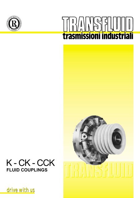
K - CK - CCK<br />
FLUID COUPLINGS<br />
drive with us
INDEX<br />
DESCRIPTION page 2<br />
OPERATION 2 ÷ 4<br />
ADVANTAGES 4<br />
PERFORMANCE CURVES 5<br />
VERSIONS 6<br />
LAYOUTS 6<br />
SELECTION 7 ÷ 10<br />
DIMENSIONS 11 ÷ 23<br />
OIL FILL 24<br />
SAFETY DEVICES 24 ÷ 27<br />
PARTICULAR INSTALLATIONS 28<br />
APPLICATIONS 29<br />
OTHER TRANSFLUID PRODUCTS 30<br />
SALES NETWORK<br />
1
DESCRIPTION & OPERATING CONDITIONS<br />
1. DESCRIPTION<br />
The TRANSFLUID coupling (K series) is a constant filling type<br />
comprising three main elements:<br />
1 - driving impeller (pump) mounted on the input shaft.<br />
2 - driven impeller (turbine) mounted on the output shaft.<br />
3 - cover, flanged to the output impeller, with an oil-tight seal.<br />
The first two elements can work both as pump and/or turbine.<br />
2. OPERATING CONDITIONS<br />
The TRANSFLUID coupling is a hydrokinetic transmission. The<br />
impellers perform like a centrifugal pump and a hydraulic turbine.<br />
With an input drive to the pump (e.g. electric motor or Diesel<br />
engine) kinetic energy is imparted to the oil in the coupling. The<br />
oil moves by centrifugal force across the blades of the turbine<br />
towards the outside of the coupling.<br />
This absorbs the kynetic energy and develops a torque which is<br />
always equal to input torque thus causing rotation of the output<br />
shaft. The wear is practically zero since there are no mechanical<br />
connections.<br />
The efficiency is influenced only by the speed difference (slip)<br />
between pump and turbine.<br />
1 - INTERNAL IMPELLER<br />
2 - EXTERNAL IMPELLER<br />
3 - COVER<br />
4 - FLEX COUPLING<br />
2<br />
The slip is essential to the functioning of the coupling: there could<br />
not be torque transmission without slip! The formula for slip, from<br />
which the power loss can be deduced is as follows:<br />
slip % =<br />
input speed – output speed<br />
input speed<br />
x 100<br />
In normal conditions (standard duty), slip can vary from 1,5%<br />
(large power) to 6% (small power).<br />
TRANSFLUID <strong>couplings</strong> follow the laws of all centrifugal<br />
machines:<br />
1 - transmitted torque is proportional to the square of input<br />
speed;<br />
2 - transmitted power is proportional to the cube of input speed;<br />
3 - transmitted power is proportional to the fifth power of circuit<br />
outside diameter.
FLUID COUPLING FITTED ON ELECTRIC MOTORS<br />
2.1. TRANSFLUID COUPLING FITTED ON ELECTRIC MOTORS<br />
The <strong>fluid</strong> coupling is mainly fitted on triphase squirrel-cage<br />
motors which supply maximum torque at 85% of rated speed.<br />
With direct-on-line starting, these motors absorb approx. 6 times<br />
nominal current.<br />
The result is an increase of: motor temperature, prime costs<br />
(specially with frequent starts) and the overcoming of limits<br />
imposed on many plants by suppliers of electrical energy.<br />
To avoid these inconveniences, some people substitute direct<br />
starting with other methods.<br />
The most usual method is star-delta starting ( ) that reduces by<br />
about 1/3 the absorbed current and torque required by direct<br />
starting. This method does not eliminate high current peaks<br />
during the initial commutation phase, and with high inertia<br />
machines it is necessary to select an oversized motor to deal with<br />
the long acceleration period during starting. With the inclusion of<br />
a TRANSFLUID coupling the motor starts on very low load with<br />
only an instantaneous current peak at switch-on (see Fig. 2).<br />
At start all the torque is available to accelerate the motor and the<br />
driving impeller. In this phase there is 100% slip until the motor<br />
reaches the maximum torque point (200% of nominal torque).<br />
Then the driven member speed increases progressively whilst<br />
slip reduces to its minimum value. (Fig. 1)<br />
% STARTING TORQUE<br />
slip 100%<br />
slip 2 ÷ 5%<br />
% INPUT SPEED<br />
Ÿ<br />
3<br />
Furthemore the <strong>fluid</strong> coupling provides protection against<br />
overload or stalling of the driven machine. In these cases, if the<br />
motor were rigidly connected, stopping of the rotor would occur<br />
immediately with overheating and instantaneous increase of<br />
current to the same values or more, of starting current.<br />
With the <strong>fluid</strong> coupling when these factors occur, the motor<br />
decelerates until 100% of slip is reached (breakdown point).<br />
At this point the absorption of current is considerably less than<br />
the starting current (about 75%). (Fig. 3)<br />
% ABSORBED CURRENT<br />
% ABSORBED CURRENT<br />
WITHOUT COUPLING<br />
WITH COUPLING<br />
% TIME<br />
slip 100%<br />
% INPUT SPEED<br />
% STARTING TORQUE
FLUID COUPLING WITH DELAYED-FILL CHAMBER<br />
THE ADVANTAGES OF FLUID COUPLING<br />
2.2 TRANSFLUID FLUID COUPLINGS WITH A DELAYED FILL<br />
CHAMBER<br />
A low starting torque is achieved and, with the standard circuit<br />
in a maximum oil fill condition, <strong>fluid</strong> <strong>couplings</strong> allow not to<br />
overcome 200% of the nominal motor torque. It is possible to<br />
furtherly limit the starting torque down to 160% of the nominal<br />
torque, by decreasing oil fill: this, on the other hand, leads to a<br />
slip and working temperature increase in the <strong>fluid</strong> coupling.<br />
The most convenient technical solution is to have <strong>fluid</strong> <strong>couplings</strong><br />
with a delayed fill chamber connected to the main circuit by<br />
means of valves with calibrated bleed orifices, externally<br />
adjustable from size 15CK (Fig. 4b).<br />
With a simple operation, it is therefore possible to adjust the<br />
starting time.<br />
In a standstill position, the delayed fill chamber contains a part<br />
of the filling oil, thus reducing the effective quantity in the working<br />
circuit (Fig. 4a): a torque reduction is obtained to allow at the<br />
same time the motor to quickly reach the steady running speed,<br />
as if started without load.<br />
During start-up, oil flows from the delayed fill chamber to the<br />
main circuit (Fig. 4b) in a proportional quantity to the rotating<br />
speed.<br />
As soon as the <strong>fluid</strong> coupling reaches the nominal speed, all the<br />
oil flows into the main circuit (Fig. 4c) and torque is transmitted<br />
with a minimum slip.<br />
With a simple delayed fill chamber, the ratio between starting<br />
and nominal torque may reach 150 %. This ratio may be furtherly<br />
reduced down to 120 % with a double delayed fill chamber,<br />
which contains a higher oil quantity, to be progressively<br />
transferred into the main circuit during the starting phase.<br />
This is then fit for very smooth start-ups with low torque<br />
absorptions, as typically required for machinery with large inertia<br />
values and for belt conveyors.<br />
The advantages of the delayed fill chamber become more and<br />
more evident when the power to be transmitted furtherly<br />
increases:<br />
the simple chamber is available from size 11CK, while the<br />
double chamber from size 15CCK.<br />
Fig. 4a<br />
AT REST<br />
Fig. 4 b<br />
ACCELERATION<br />
4<br />
3. SUMMARY OF THE ADVANTAGES GIVEN BY FLUID<br />
COUPLINGS<br />
– very smooth start-ups<br />
– reduction of current absorptions during the starting phase: the<br />
motor starts with very low load<br />
– protection of the motor and the driven machine from jams and<br />
overloads<br />
– utilization of asynchronous squirrel cage motors instead of<br />
special motors with soft starter devices<br />
– higher duration and operating convenience of the whole drive<br />
train, thanks to the protection function achieved by the <strong>fluid</strong><br />
coupling<br />
– higher energy saving, thanks to the current peaks reduction<br />
– limited starting torque down to 120% in the versions with a<br />
double delayed fill chamber<br />
– same torque at input and output: the motor can supply the<br />
maximum torque also when load is jammed<br />
– torsional vibration absorption for internal combustion engines,<br />
thanks to the presence of a <strong>fluid</strong> as a power transmission<br />
element<br />
– possibility to achieve a high number of start-ups, also with an<br />
inversion of the rotation sense<br />
– load balancing in case of a double motor drive: <strong>fluid</strong> <strong>couplings</strong><br />
automatically adjust load speed to the motors speed<br />
– high efficiency<br />
– minimum maintenance<br />
– Viton rotating seals<br />
– cast iron and steel material with anticorrosion treatment<br />
valvola valve<br />
grano calibrated calibrato plug<br />
Fig. 4 c<br />
RUNNING
STARTING TORQUE CHARACTERISTICS<br />
4. CHARACTERISTIC CURVES<br />
MI : transmitted torque from <strong>fluid</strong> coupling<br />
Mm : starting torque of the electric motor<br />
Mn : nominal torque at full load<br />
...... : accelerating torque<br />
K type<br />
(standard circuit)<br />
CK type<br />
(circuit with a<br />
delayed chamber)<br />
CCK type<br />
(circuit with a double<br />
delayed chamber)<br />
Torque<br />
200%<br />
100%<br />
Torque<br />
200%<br />
100%<br />
Torque<br />
200%<br />
100%<br />
Mm<br />
MI<br />
0 5 10 Time [s]<br />
Mm<br />
0 5 10 Time [s]<br />
Mm<br />
MI<br />
5<br />
Mn<br />
Mn<br />
MI Mn<br />
0 5 10 Time [s]<br />
180÷200%<br />
160÷180%<br />
120÷150%
PRODUCTION PROGRAM<br />
5 VERSIONS<br />
5.1 IN LINE<br />
KR-CKR-CCKR : basic coupling (KR), with a simple<br />
(CKR) or double (CCKR) delayed fill<br />
chamber.<br />
KRG-CKRG-CCKRG : basic coupling with elastic coupling<br />
KRM-CKRM-CCKRM (clamp type), or superelastic.<br />
KRB-CKRB-CCKRB : like ..KRG, but with brake drum or<br />
…KRBP brake disc.<br />
KRD-CKRD-CCKRD : basic coupling ..KR with output shaft. It<br />
allows the utilization of other flex<br />
<strong>couplings</strong>; it is possible to place it (with<br />
a convenient housing) between the<br />
motor and a hollow shaft gearbox.<br />
EK : <strong>fluid</strong> coupling fitted with a bell housing, to<br />
be placed between a flanged electric<br />
motor and a hollow shaft gearbox.<br />
KCM-CKCM-CCKCM: basic coupling for half gear <strong>couplings</strong>.<br />
KCG-CKCG-CCKCG : basic ..KCM with half gear <strong>couplings</strong>. On<br />
request, layout with brake drum or brake<br />
disc.<br />
KDM-CKDM-CCKDM: <strong>fluid</strong> coupling with disc <strong>couplings</strong>.<br />
…KDMB : like ..KDM, but with brake drum or<br />
…KDMBP brake disc.<br />
KSD<br />
1<br />
KSI<br />
6.1 IN LINE VERSIONS MOUNTING EXAMPLES<br />
Fig. A Horizontal axis between the motor and the driven<br />
machine (KR-CKR-CCKR and similar).<br />
Fig. B It allows a radial disassembly without moving the<br />
motor and the driven machine (KCG-KDM and similar).<br />
Fig. C Between a flanged electric motor and a hollow shaft<br />
gearbox by means of a bell housing (..KRD and EK).<br />
Fig. D Vertical axis mounting between the electric motor and<br />
a gearbox or driven machine. In case of order,<br />
please specify mounting type 1 or 2.<br />
Fig. E Between the motor and a supported pulley for high<br />
powers and heavy radial loads.<br />
Fig. G<br />
2<br />
KCM<br />
CKR - CCKR<br />
6<br />
KR<br />
5.2 PULLEY<br />
Fig. C<br />
Fig. Fig. E<br />
KRD<br />
CKRG - C<br />
KRG<br />
EK<br />
CKRBP - CCKRBP<br />
N.B.: The ..KCG - ..KDM versions allow a radial disassembly without moving the motor or the driven machine.<br />
KSD–CKSD–CCKSD : basic coupling foreseen for a flanged pulley,<br />
with simple (CK..) or double (CCK..) delayed<br />
fill chamber.<br />
KSI-CKSI-CCKSI : <strong>fluid</strong> coupling with an incorporated pulley,<br />
which is fitted from inside.<br />
KSDF-CKSDF-CCKS..: basic ..KSD coupling with flanged pulley,<br />
externally mounted and therefore to be easily<br />
disassembled.<br />
Fig. Fig. AA<br />
Fig. Fig. B B<br />
Fig. Fig. D<br />
Fig. F<br />
1<br />
2<br />
6. 2 PULLEY VERSIONS MOUNTING EXAMPLES<br />
Fig. F Horizontal axis.<br />
Fig. G Vertical axis. When ordering, please specify mounting<br />
type 1 or 2.
FLUID COUPLING SELECTION<br />
7. SELECTION<br />
7.1 SELECTION CHART<br />
The chart below may be used to select a unit size from the<br />
horsepower and input speed. If the selection point falls on a size<br />
limit line dividing one size from the other, it is advisable to select<br />
the larger size with a proportionally reduced oil fill.<br />
GENERAL REFERENCE HORSEPOWER CHART<br />
HP kW<br />
HORSEPOWER<br />
INPUT SPEED RPM<br />
THE CURVES SHOW LIMIT CAPACITY OF COUPLING<br />
7<br />
Tab. A
FLUID COUPLING SELECTION<br />
7.2 SELECTION TABLE<br />
Fluid <strong>couplings</strong> for standard electric motors.<br />
TYPE<br />
MOTOR 3000 rpm • 1800 rpm 1500 rpm<br />
• 1200 rpm<br />
SHAFT<br />
DIA.<br />
71 14<br />
80 19<br />
90S 24<br />
90L 24<br />
100L 28<br />
112M 28<br />
132 38<br />
132M 38<br />
160M 42<br />
160L 42<br />
180M 48<br />
180L 48<br />
200L 55<br />
225S 60<br />
225M<br />
55 (3000)<br />
60<br />
250M<br />
60 (3000)<br />
65<br />
280S<br />
65 (3000)<br />
75<br />
280M<br />
65 (3000)<br />
75<br />
315S<br />
65 (3000)<br />
80<br />
315M<br />
65 (3000)<br />
80<br />
355S<br />
80 (3000)<br />
100<br />
355M<br />
80 (3000)<br />
100<br />
NO - STANDARD<br />
MOTORS<br />
kW HP COUPLING<br />
kW HP COUPLING kW HP COUPLING kW HP COUPLING<br />
0,37<br />
0,55<br />
0,75<br />
1,1<br />
0,5<br />
0,75<br />
1<br />
1,5<br />
_ _<br />
1,5 2 6 K<br />
2,2 3<br />
3 4<br />
4 5,5 7 K<br />
5,5<br />
7,5<br />
7,5<br />
10<br />
18,5<br />
(1)<br />
_ _ _<br />
11<br />
15<br />
15<br />
20<br />
18,5 25 9 K<br />
22 30<br />
(1)<br />
_ _ _<br />
30<br />
37<br />
40<br />
50<br />
11 K (1)<br />
_ _ _<br />
45 60 11 K (1)<br />
55 75 13 K (1)<br />
75 100<br />
90 125<br />
13 K<br />
110 150<br />
132<br />
160 220<br />
(2)<br />
0,25<br />
0,37<br />
0,55<br />
0,75<br />
0,35<br />
0,5<br />
0,75<br />
1<br />
6 K<br />
0,25<br />
0,37<br />
0,55<br />
0,75<br />
0,35<br />
0,5<br />
0,75<br />
1<br />
6 K<br />
0,25<br />
0,37<br />
0,55<br />
0,33<br />
0,5<br />
0,75<br />
_<br />
7 K<br />
0,25<br />
0,37<br />
0,55<br />
0,33<br />
0,5<br />
0,75<br />
_<br />
7 K<br />
1,1 1,5<br />
1,1 1,5<br />
0,75 1<br />
0,75 1<br />
1,5 2<br />
1,5 2<br />
7 K<br />
1,1 1,5<br />
1,1 1,5<br />
8 K<br />
2,2<br />
3<br />
3<br />
4<br />
7 K<br />
2,2<br />
3<br />
3<br />
4<br />
1,5 2 8 K 1,5 2 9 K<br />
4 5,5<br />
4 5,5<br />
8 K<br />
2,2 3<br />
2,2 3<br />
5,5<br />
7,5<br />
7,5<br />
10<br />
8 K 5,5<br />
7,5<br />
7,5<br />
10<br />
9 K<br />
3<br />
4<br />
5,5<br />
4<br />
5,5<br />
7,5<br />
9 K<br />
11 K<br />
3<br />
4<br />
5,5<br />
4<br />
5,5<br />
7,5<br />
11 K<br />
11 15 9 K 11 15<br />
11 K<br />
7,5 10<br />
12 K<br />
7,5 10<br />
12 K<br />
15 20 11 K 15 20<br />
11 15<br />
11 15 13 K<br />
18,5 25<br />
12 K<br />
(11 K) 18,5 25<br />
_ _ _ _ _ _<br />
12 K<br />
22 30 12 K 22 30<br />
15 20<br />
15 20<br />
30<br />
37<br />
40<br />
50<br />
13 K<br />
(12 K)<br />
30<br />
37<br />
40<br />
50<br />
13 K<br />
22<br />
_<br />
25<br />
30<br />
_<br />
13 K<br />
18,5<br />
22<br />
_<br />
25<br />
30<br />
_<br />
15 K<br />
_<br />
13 K<br />
15 K<br />
45 60<br />
45 60<br />
15 K<br />
30 40<br />
30 40 17 K<br />
55 75 15 K 55 75<br />
37 50<br />
37 50<br />
75 100<br />
17 K<br />
(15 K) 75 100<br />
17 K<br />
45 60 17 K 45 60<br />
19 K<br />
90 125<br />
90 125<br />
55 75<br />
55 75<br />
17 K<br />
21 K<br />
110 150<br />
110 150<br />
75 100 19 K<br />
75 100<br />
180<br />
_<br />
132<br />
160<br />
180<br />
220<br />
19 K<br />
132<br />
160<br />
180<br />
220<br />
19 K<br />
21 K<br />
90<br />
110<br />
125<br />
150<br />
21 K<br />
90<br />
110<br />
125<br />
150<br />
24 K<br />
200<br />
250<br />
270<br />
340<br />
_<br />
_<br />
250<br />
315<br />
340<br />
430<br />
21 K<br />
24 K<br />
250<br />
315<br />
340<br />
430<br />
24 K<br />
160<br />
200<br />
250<br />
270<br />
270<br />
340<br />
24 K<br />
27 K<br />
160<br />
200<br />
250<br />
220<br />
270<br />
340<br />
27 K<br />
29 K<br />
max max max<br />
700 952 27 K 510 700 27 K 440 598 29 K 370 500 29 K<br />
• Power refer to motors connected at 380V - 60 Hz<br />
(1) Special version, 24 hours service<br />
(2) Only for KR<br />
NB: The <strong>fluid</strong> coupling size is tied to the motor shaft dimensions<br />
1000 1360<br />
29 K<br />
8<br />
810 1100<br />
1300 1740<br />
29 K<br />
34 K<br />
2300 3100 D 34 K<br />
800 1088<br />
1350 1836<br />
34 K<br />
D 34 K<br />
1000 rpm<br />
Tab. B<br />
kW HP COUPLING<br />
600 800<br />
950 1300<br />
34 K<br />
D34 K
FLUID COUPLING SELECTION<br />
7.3 PERFORMANCE CALCULATIONS<br />
For frequent starts or high inertia acceleration, it is necessary to<br />
first carry out following calculations. For this purpose it is<br />
necessary to know:<br />
Pm - input power kW<br />
nm - input speed rpm<br />
PL - power absorbed by the load at rated speed kW<br />
nL - speed of driven machine rpm<br />
J - inertia of driven machine Kgm<br />
T - ambient temperature °C<br />
The preliminary selection will be made from the selection graph<br />
Tab. A depending upon input power and speed.<br />
Then check:<br />
A) acceleration time.<br />
B) max allowable temperature.<br />
C) max working cycles per hour<br />
A) Acceleration time t a :<br />
n u • J r<br />
t a = (sec) where:<br />
9,55 • M a<br />
nu = coupling output speed (rpm)<br />
2<br />
Jr = inertia of driven machine referred to coupling shaft (Kgm )<br />
Ma = acceleration torque (Nm)<br />
n u = n m • (<br />
100 - S<br />
)<br />
where S is the percent slip derived from the characteristic<br />
curves of the coupling respect to the absorbed torque ML. If S is not known accurately, the following assumptions may<br />
be made for initial calculations:<br />
4 up to size 13”<br />
3 from size 15” up to size 19”<br />
2 for all larger sizes.<br />
J r = J • (<br />
n L<br />
100<br />
)<br />
n u<br />
PD GD<br />
Note! J = or<br />
4 4<br />
M a = 1,65 M m - M L<br />
2<br />
2 2<br />
9550<br />
where: Mm = (Nominal Torque)<br />
• Pm nm 9550<br />
dove: ML = (Absorbed Torque)<br />
• PL nu 2<br />
9<br />
B) Max allowable temperature.<br />
For simplicity of calculation, ignore the heat dissipated during<br />
acceleration.<br />
Coupling temperature rise during start-up is given by:<br />
Ta =<br />
Q<br />
C<br />
(°C)<br />
where: Q = heat generated during acceleration (kcal)<br />
C = total thermal capacity (metal and oil) of coupling<br />
selected from Tab. C (kcal/°C).<br />
Q = •(<br />
+ ) (kcal)<br />
The final coupling temperature reached at the end of the<br />
acceleration cycle will be:<br />
T f = T + T a + T L (°C)<br />
where: T f = final temperature (°C)<br />
T = ambient temperature (°C)<br />
T a = temperature rise during acceleration (°C)<br />
T L = temperature during steady running (°C)<br />
TL= 2,4 • P •<br />
L S<br />
(°C)<br />
K<br />
where: K = factor from Tab. D<br />
T f =must not exceed 110°C for <strong>couplings</strong> with<br />
standard gaskets<br />
T f =must not exceed 150°C for <strong>couplings</strong> with<br />
Viton gaskets<br />
C) Max working cycles per hour H<br />
In addition to the heat generated in the coupling by slip<br />
during steady running, heat is also generated (as calculated<br />
above) during the acceleration period. To allow time for this<br />
heat to be dissipated, one must not exceed the max<br />
allowable number of acceleration cycles per hour.<br />
H max =<br />
nu 10<br />
4<br />
3600<br />
ta + tL J •<br />
r nu 76,5<br />
where t L = minimum working time<br />
M •<br />
L ta 8<br />
tL= 10 • 3 Q<br />
(sec)<br />
T2 a + T •<br />
L K<br />
( )
FLUID COUPLING SELECTION<br />
7.4 CALCULATION EXAMPLE<br />
Assuring: Pm = 20 kW n m = 1450 rpm<br />
Supponendo: P L = 12 kW n L = 700 rpm<br />
Supponendo: J = 350 kgm<br />
Supponendo: T = 25 °C<br />
Transmission via belts.<br />
From selection graph on Tab. A, selected size is 12K.<br />
A) Acceleration time<br />
From curve TF 5078-X (supplied on request) slip S = 4%<br />
100 - 4<br />
nu = 1450 • ( )= 1392 rpm<br />
100<br />
2 700<br />
Jr = 350 • ( )= 88,5 Kgm<br />
1392<br />
9550 •<br />
20<br />
Mm = = 131 Nm<br />
1450<br />
9550 • 12<br />
ML = = 82 Nm<br />
1392<br />
Ma = 1,65 •131 • 82 = 134 Nm<br />
1392 • 88,5<br />
ta = = 96 sec<br />
9,55 • 134<br />
B) Max allowable temperature<br />
1392 88,5 • 1392<br />
+<br />
4<br />
10 76,5<br />
C = 4,2 kcal/°C (Tab. C)<br />
Q = • ( ) = 361 kcal<br />
Ta =<br />
361<br />
4,2<br />
= 86 °C<br />
K = 8,9 (Tab. D)<br />
12<br />
TL = 2,4 = 13 °C<br />
• 4<br />
•<br />
8,9<br />
T f = 25 + 86 + 13 = 124 °C<br />
Viton gaskets needed<br />
C) Max working cycles per hour<br />
tL = 10 • 361<br />
= 724 sec<br />
86<br />
2 + 13 3<br />
( ) • 8,9<br />
3600<br />
H = = 4 starts per hour<br />
96 + 724<br />
2<br />
2<br />
82 •<br />
96<br />
8<br />
10<br />
FACTOR K<br />
Size<br />
6<br />
7<br />
8<br />
9<br />
11<br />
12<br />
13<br />
15<br />
17<br />
19<br />
21<br />
24<br />
27<br />
29<br />
34<br />
D34<br />
Tab. C<br />
THERMAL CAPACITY<br />
K<br />
kcal/°C<br />
0,6<br />
1,2<br />
1,5<br />
2,5<br />
3,2<br />
4,2<br />
6<br />
9<br />
12,8<br />
15,4<br />
21,8<br />
29<br />
43<br />
56<br />
92<br />
138<br />
CK<br />
kcal/°C<br />
OUTPUT SPEED rpm<br />
--<br />
3,7<br />
5<br />
6,8<br />
10<br />
14,6<br />
17,3<br />
25,4<br />
32<br />
50<br />
63<br />
99<br />
–<br />
CCK<br />
kcal/°C<br />
--<br />
10,3<br />
15,8<br />
19,4<br />
27,5<br />
33,8<br />
53,9<br />
66,6<br />
101<br />
–<br />
Tab. D<br />
FACTOR K
FLUID COUPLING SERIES 6 ÷ 19 KR-CKR-CCKR<br />
8. DIMENSIONS<br />
Size<br />
6<br />
7<br />
8<br />
9<br />
only for size “6” only for size “6”<br />
Ø40H7<br />
U<br />
2.5<br />
M<br />
±0.1 f7<br />
P<br />
W C<br />
O<br />
T<br />
V<br />
Q<br />
J<br />
S<br />
R<br />
E<br />
F A<br />
– D BORES RELATIVE TO TAPER BUSHES WITH A KEYWAY ACCORDING TO ISO 773 - DIN 6885/1<br />
PARTICULAR CASES:<br />
• CYLINDRICAL BORE WITHOUT TAPER BUSH<br />
•• CYLINDRICAL BORE WITHOUT TAPER BUSH, WITH A REDUCED KEYWAY (DIN 6885/2) - FOR 7 AND 8KR, Q DIMENSION IS M14<br />
••• TAPER BUSH WITHOUT KEYWAY<br />
– WHEN ORDERING, SPECIFY: SIZE, MODEL, D DIAMETER<br />
EXAMPLE: 11CKR - D 42<br />
* SEE DRAWING DIMENSIONS ARE SUBJECT TO ALTERATION WITHOUT NOTICE<br />
11<br />
N M<br />
±0.1 f7<br />
KR KR<br />
CKR - CCKR CKR - CCKR<br />
Dimensions<br />
bussola taper bush conica<br />
J 1<br />
D<br />
NB: The arrows indicate input and output in the standard version.<br />
I<br />
P<br />
O<br />
In case of installation on shafts without<br />
shoulders, please contact Trans<strong>fluid</strong><br />
T<br />
B1<br />
B2<br />
C1<br />
C2<br />
albero cylindrical con foro bore cilindico<br />
D J J 1 A B B 1 B 2 C C 1 C 2 E F I M N O P Q R S T U V W Z Weight Kg<br />
(without oil)<br />
KR CKR CCKR KR CKR CCKR Nr. Ø<br />
28 38<br />
11<br />
42••• 48••<br />
111<br />
60<br />
110<br />
80<br />
110<br />
325 107 68,5<br />
154<br />
201 27 195<br />
60 88,9 8 M8 M20 42 56<br />
83<br />
M10 M12<br />
M16<br />
107 27 19 15 12 14,5 2,75 3,35<br />
28 38<br />
12<br />
42••• 48••<br />
60<br />
110<br />
80<br />
110<br />
370 122<br />
75<br />
221 24 145<br />
224<br />
42<br />
83<br />
M10 M12<br />
M16<br />
15,5 18,5 4,1 4,8<br />
13<br />
42 48<br />
143<br />
110<br />
398 137 180 240 28 179 80 122,2<br />
84 M16<br />
7 142 17 17 24 27 5,2 5,8<br />
55••• 60•••<br />
48 55<br />
15<br />
60 65•••<br />
145<br />
110 58,5<br />
110<br />
140<br />
460 151 87 135 205 273 321 35 206 259 90 136<br />
5 8<br />
74 104<br />
80 70<br />
100<br />
M20<br />
M16 M20<br />
M20<br />
156<br />
34<br />
19 19 37 41 48,7 7,65 8,6 9,3<br />
17<br />
48<br />
60<br />
55<br />
65••• 145<br />
110<br />
140 520 170 37<br />
M10 M27<br />
80<br />
103<br />
M16 M20<br />
M20 8<br />
51 57 66 11,7 13,6 14,9<br />
75• 80• 140 170<br />
96 176 223 303 383 225 337 125 160 15 12<br />
103 132<br />
180 34 24 19<br />
48 55 110 80 M16 M20<br />
19 60 65••• 145 140 565 190 17 103<br />
M20<br />
58 64 73 14,2 16,5 18,5<br />
75• 80• 140 170 103 133<br />
J 1<br />
D G7<br />
Oil<br />
max lt<br />
KR CKR CCKR KR CKR CCKR<br />
19• 24• – 45 55 195 60 90,5 29 88 * 53 * 4 – – – – 68 – – 16,5 2,7 0,50<br />
19 24 40 50<br />
228 77 112 22<br />
M12 27 35 M6 M8<br />
5,1 0,92<br />
28 38••<br />
69<br />
60 80<br />
114 40 73 3<br />
M7 M12 M14 40 56 M10 M12<br />
88 21 12 14<br />
24 50<br />
256 91<br />
–<br />
117<br />
–<br />
18<br />
– M12 36 M8<br />
5,5<br />
–<br />
1,5<br />
–<br />
28 38•• 60 80 M12 M14 41 61 M10 M12<br />
28 38 60 80<br />
295 96 145 31<br />
6 43 54 M10 M12 6<br />
10 1,95<br />
42••• 110 110 – – 128 79 M16 – –
FLUID COUPLING SERIES 6 ÷ 19 KRG-…KRB-…KRD<br />
Size<br />
KRB<br />
(with (Con fascia brake freno) drum)<br />
X1 X<br />
Dimensions<br />
H7<br />
KRBP<br />
(with (Con disco brake freno) disc)<br />
G1<br />
j7<br />
KRD<br />
Z<br />
L 1<br />
C 3<br />
C C 1 C 2 C 3 C 4 C 5 G G 1 H K L L 1 Flex Brake Brake Z<br />
coupling drum disc<br />
12<br />
Weight Kg<br />
(without oil)<br />
KRG CKRG CCKRG KRD CKRD CCKRD max X x Y X1x Y1 KRG CKRG CCKRG KRD CKRD CCKRD<br />
6 149 107 28 19 73 40 30 BT 02 on request 3,9 3<br />
7 189<br />
–<br />
133<br />
– 42 28 110 60 40 BT 10 160 x 60<br />
8,3<br />
–<br />
5,7<br />
–<br />
8 194 138 2<br />
on request –<br />
8,7 6,1<br />
9 246 – 176 – 38 16 – 11,6 –<br />
11<br />
255<br />
302<br />
185<br />
232 55<br />
42<br />
132<br />
80<br />
50 BT 20<br />
160 x 60<br />
200 x 75<br />
18 20,5 13 15,5<br />
12<br />
322 252<br />
21,5 24,5 16,7 19,7<br />
13<br />
15<br />
285<br />
343<br />
345<br />
411 459<br />
212<br />
230<br />
272<br />
298 346<br />
70<br />
80<br />
48<br />
60<br />
170<br />
3<br />
110<br />
60<br />
80<br />
BT 30<br />
BT 40<br />
200 x 75<br />
250 x 95<br />
250 x 95<br />
315 x 118<br />
400 x 30<br />
450 x 30<br />
400 x 30<br />
450 x 30<br />
5<br />
35<br />
34<br />
50,3<br />
37<br />
54,3 62<br />
26,3<br />
40,4<br />
29,3<br />
44,4 52,1<br />
17<br />
19<br />
362 442 522 263 343 423 90 75 250 110 100 BT 50 315 x 118<br />
400 x 150<br />
445 x 30<br />
450 x 30<br />
15<br />
77<br />
84<br />
83<br />
90<br />
92<br />
99<br />
58,1<br />
65,1<br />
64,1<br />
71,1<br />
73,1<br />
80,1<br />
– G1 SHAFT BORE WITH A KEYWAY ACCORDING TO ISO 773 - DIN 6885/1<br />
– WHEN ORDERING, SPECIFY: SIZE - MODEL - D DIAMETER<br />
– UPON REQUEST: BORE G 1 MACHINED; G SPECIAL SHAFT<br />
– FOR …KRB - KRBP SERIES SPECIFY X AND Y OR X 1 AND Y 1 DIAMETER<br />
EXAMPLE: 9KRB - D38 - BRAKE DRUM = 160x60<br />
L<br />
Y<br />
Y 1<br />
C<br />
K<br />
KRG<br />
KRD<br />
C1<br />
C2<br />
KRG CKRG - CKRG CCKRG-<br />
CCKRG<br />
NB: The arrows indicate input and output in the standard version.<br />
C4<br />
C5<br />
CKRD - CCKRD CKRD - CCKRD<br />
DIMENSIONS ARE SUBJECT TO ALTERATION WITHOUT NOTICE
FLUID COUPLING SERIES 21 ÷ 34 KR-CKR-CCKR<br />
Size<br />
21<br />
24<br />
27<br />
29<br />
34<br />
W<br />
W<br />
O<br />
O<br />
P<br />
P<br />
±0.1 f7<br />
M N U V<br />
±0.1 f7<br />
M N U V<br />
KR<br />
Dimensions<br />
T<br />
T<br />
KR<br />
KR<br />
Z<br />
Z<br />
Q<br />
Q<br />
C<br />
B C E<br />
B E<br />
24<br />
1924<br />
M14 Nr.12 19<br />
M14 Nr.12<br />
570 Ø 570<br />
± 0,1<br />
± 0,1<br />
308 Ø 308<br />
Ø 200 f 7<br />
f 7<br />
200<br />
Ø<br />
Ø<br />
Ø<br />
6<br />
6<br />
S<br />
S<br />
R<br />
R<br />
J<br />
J<br />
D A<br />
G7 F<br />
D A<br />
G7 F<br />
C<br />
C<br />
22<br />
722<br />
M16 Nr.10 7<br />
M16 Nr.10<br />
Ø 480 ± 0,1<br />
Ø 480 ± 0,1<br />
Ø 200 f 7<br />
Ø 200 f 7<br />
I N M<br />
±0.1 f7<br />
I N M<br />
±0.1 f7<br />
P<br />
P<br />
O<br />
O<br />
T<br />
T<br />
Z<br />
Z<br />
CKR - CCKR<br />
CKR - CCKR<br />
C1<br />
C2 C1<br />
C2<br />
34KR 34KR 34CKR 34CKR - - 34CCKR<br />
34CCKR<br />
34KR<br />
34CKR - 34CCKR<br />
13<br />
B1<br />
B2 B1<br />
B2<br />
NB: The arrows indicate input and output in the standard version.<br />
C1<br />
C2 C1<br />
C2<br />
Size<br />
Dimensions<br />
D J A B B 1 B 2 C C 1 C 2 E F I M N O P Q R S T U V W Z<br />
KR CKR CCKR KR CKR CCKR Nr. Ø<br />
•80 90 170<br />
620 205<br />
260 360 450<br />
45<br />
130 M20 M24<br />
•❒100 210<br />
110 200<br />
295 395 485<br />
250 400 160 228 5 M14 M36<br />
165 M24<br />
•80 90 170<br />
710 229<br />
260 360 450 21 130 M20 M24<br />
•❒100 210 295 395 485 56 8 165 M24 14<br />
120 max 210 780 278 297 415 515 6 315<br />
200 275 7 M16<br />
135 max 240 860 295 131 231 326 444 544 18 350 537 M45<br />
150 max 265 1000 368 387 518 618 19 400 * * * * *<br />
CKR - CCKR<br />
167 M24<br />
(for max bore)<br />
167 M24<br />
(for max bore)<br />
200 M36<br />
(for max bore)<br />
Weight Kg<br />
(without oil)<br />
255 40 15 30<br />
– –<br />
308 33<br />
– –<br />
* * – – *<br />
• STANDARD DIMENSIONS WITH A KEYWAY ACCORDING TO ISO 773 - DIN 6885/1<br />
❒<br />
*<br />
REDUCED DEPTH KEYWAY AS PER DIN 6885/2<br />
SEE DRAWING Pag13<br />
– WHEN ORDERING, SPECIFY: SIZE, MODEL, D DIAMETER<br />
Pag13<br />
EXAMPLE: 2ICCKR - D 80 DIMENSIONS ARE SUBJECT TO ALTERATION WITHOUT NOTICE<br />
21<br />
24<br />
27<br />
29<br />
34<br />
Oil<br />
max lt<br />
KR CKR CCKR KR CKR CCKR<br />
87 97 105 19 23 31<br />
105 115 123 28,4 31,2 39<br />
158 176 195 42 50 61<br />
211 229 239 55 63 73<br />
337 352 362 82,5 92,5 101
FLUID COUPLING SERIES 21 ÷ 34…KRG-…KRB-…KRBP-…KRD<br />
Size<br />
21•<br />
24•<br />
27<br />
29<br />
34<br />
KRB<br />
(with brake drum)<br />
(Con fascia freno)<br />
X1 X H G<br />
H7<br />
Dimensions<br />
KRBP<br />
(with (Con brake disco disc) freno)<br />
G1<br />
j7<br />
KRD<br />
Z<br />
L<br />
Y<br />
Y 1<br />
C<br />
K<br />
KRG<br />
L 1<br />
C 3<br />
KRD<br />
C C 1 C 2 C 3 C 4 C 5 G G 1 H K L L 1 Flex Brake Brake Z<br />
coupling drum disc<br />
• FOR BORES D 100 INCREASE DIMENSIONS BY 35 mm.<br />
– G1 SHAFT WITH A KEYWAY ACCORDING TO ISO 773 - DIN 6885/1<br />
– UPON REQUEST, G FINISHED BORE AND G1 SPECIAL SHAFT DIAMETER<br />
Pag14<br />
– WHEN ORDERING, SPECIFY: SIZE - MODEL - D DIAMETER FOR …KRB OR …KRBP, SPECIFY X AND Y OR X1 AND Y1 DIMENSIONS BRAKE DRUM OR DISC<br />
EXAMPLE: 19KRBP - D80 - BRAKE DISC 450 x 30<br />
DIMENSIONS ARE SUBJECT TO ALTERATION WITHOUT NOTICE<br />
14<br />
Weight kg<br />
(without oil)<br />
KRG CKRG CCKRG KRD CKRD CCKRD max X x Y X1xY1 KRG CKRG CCKRG KRD CKRD CCKRD<br />
560 x 30<br />
433• 533• 623• 292• 392• 482• 110 90 290 3 140 120 BT60<br />
400 x 150 630 x 30<br />
45<br />
129 139 147 99,5 109,5 117,5<br />
710 x 30<br />
500 x 190 795 x 30<br />
147 157 165 117,5 127,5 135,5<br />
484<br />
513<br />
602<br />
631<br />
702<br />
731<br />
333<br />
362<br />
451<br />
480<br />
551<br />
580<br />
130 100 354 4 150 140 BT80 500 x 190<br />
710 x 30<br />
795 x 30 20<br />
228<br />
281<br />
246<br />
299<br />
265<br />
309<br />
178<br />
231<br />
186<br />
249<br />
215<br />
259<br />
595 726 826 437 568 668 160 140 425 5 180 150 CT90 630 x 265 1000 x 30 50 449 464 474 358 373 383<br />
C1<br />
C2<br />
KRG CKRG CKRG - CCKRG - CCKRG<br />
NB: The arrows indicate input and output in the standard version.<br />
C4<br />
C5<br />
CKRD CKRD - CCKRD - CCKRD
FLUID COUPLING SERIES 7 ÷ 34 KCM-CKCM-CCKCM<br />
E<br />
F<br />
0<br />
+0.05<br />
A D D B<br />
Size<br />
H<br />
H<br />
C<br />
Dimensions<br />
F1<br />
• INTERCHANGEABLE WITH STANDARD VERSION<br />
– WHEN ORDERING, SPECIFY: SIZE - MODEL<br />
EXAMPLE: 34CCKCM<br />
E<br />
0<br />
+0.05<br />
KCM CKM<br />
CKCM CKCM - CCKCM-<br />
CCKCM<br />
NB: The arrows indicate input and output in the standard version.<br />
15<br />
C1<br />
C2<br />
THIS FLUID COUPLING IS FORESEEN FOR THE ASSEMBLY OF HALF GEAR COUPLINGS<br />
A B C C1C2 D E F F1H L Weight kg<br />
(without oil)<br />
Gear<br />
coupling<br />
KCM CKCM CCKCM<br />
Nr. Ø KCM CKCM CCKCM size<br />
7<br />
8<br />
228<br />
256<br />
116<br />
140<br />
145 –<br />
95,25 6 6,4<br />
1/4<br />
28<br />
UNF<br />
17<br />
7,3<br />
8,1 –<br />
1”<br />
S<br />
9<br />
11<br />
12<br />
13<br />
295<br />
325<br />
370<br />
398<br />
152,5<br />
177<br />
186<br />
198<br />
208<br />
233<br />
265<br />
283,5<br />
–<br />
122,22 8 9,57<br />
7 6,5<br />
3/8<br />
24<br />
UNF<br />
18,5<br />
21<br />
14<br />
16<br />
21<br />
28<br />
18,5<br />
24<br />
31<br />
–<br />
1” 1/2<br />
S<br />
15 460 248 327 375 24,5 47,2 51 52,9<br />
17<br />
19<br />
21<br />
24<br />
520<br />
565<br />
620<br />
710<br />
213<br />
240<br />
250<br />
315<br />
332<br />
417<br />
412<br />
507<br />
177,8<br />
203,2<br />
10<br />
12<br />
12,75 9,5 10<br />
1/2<br />
20<br />
UNF 25,5<br />
66,2<br />
75<br />
109<br />
129<br />
72<br />
81<br />
119<br />
139<br />
81<br />
90<br />
127<br />
147<br />
2” 1/2<br />
S<br />
3”<br />
S<br />
27<br />
29<br />
780<br />
860<br />
280<br />
367<br />
396<br />
526<br />
555<br />
626<br />
655<br />
241,3<br />
8 19,05 22 28<br />
3/4<br />
10 50<br />
206<br />
255<br />
229<br />
278<br />
239<br />
288<br />
3” 1/2<br />
E<br />
34 1000 318 471 634 734 279,4<br />
UNC<br />
436 444 454<br />
4”<br />
E<br />
SUPERSTANDARD<br />
VERSION<br />
C C 1 C 2<br />
140•<br />
145•<br />
189<br />
–<br />
–<br />
198 245<br />
198• 265•<br />
223,5 283,5•<br />
251• 319 367<br />
296 376 456<br />
320 420 510<br />
408 526• 626•<br />
437 555• 655•<br />
510 634• 734•<br />
Gear<br />
coupling<br />
size<br />
DIMENSIONS ARE SUBJECT TO ALTERATION WITHOUT NOTICE<br />
1”<br />
S<br />
1” 1/2<br />
S<br />
2” 1/2<br />
S<br />
3” 1/2<br />
E<br />
4”<br />
E
FLUID COUPLING SERIES 7 ÷ 34 KCG-CKCG-CCKCG<br />
N<br />
A G<br />
G<br />
I<br />
C<br />
N<br />
M I<br />
KCG KCG CKCG - CCKCGCKCG<br />
- CCKCG<br />
KCGB<br />
(with (Con fascia brake freno) drum)<br />
KCGBP<br />
(Con (with disco brake freno) disc)<br />
Brake Fascia drum o disco or freno disc a upon richiesta request<br />
Size<br />
•<br />
••<br />
Dimensions<br />
A C C 1 C 2 G I M M 1 M 2 N<br />
KCG CKCG CCKCG max KCG CKCG CCKCG<br />
S = SHROUDED SCREWS<br />
E = EXPOSED SCREWS<br />
••• INTERCHANGEABLE WITH STANDARD VERSION<br />
– WHEN ORDERING, SPECIFY: SIZE - MODEL<br />
EXAMPLE: 21CKCG<br />
16<br />
C1<br />
M1<br />
M2<br />
NB: The arrows indicate input and output in the standard version.<br />
FLUID COUPLING FITTED WITH HALF GEAR COUPLINGS, TO BE RADIALLY<br />
DISASSEMBLED WITHOUT MOVING THE MACHINES<br />
Gear coupling<br />
Size Weight Kg<br />
228<br />
256<br />
295<br />
325<br />
370<br />
229<br />
234<br />
–<br />
278,6<br />
287,6 334,6<br />
299,6 366,6<br />
–<br />
50<br />
65<br />
43<br />
49,3<br />
143<br />
148<br />
180<br />
189<br />
201<br />
–<br />
236<br />
268<br />
–<br />
44,5<br />
50,8<br />
4<br />
8<br />
398 309,6 385,1 211 286,5<br />
460 407 486 534 253 332 380<br />
520<br />
565<br />
409 491 571<br />
95 77<br />
255 337 417<br />
79,5 23,5<br />
620<br />
710<br />
502 604 694 111 91 320 422 512 93,5 35,2<br />
780 586 745 845<br />
134 106,5 373 532 632 7<br />
8<br />
9<br />
11<br />
12<br />
•<br />
1”<br />
S<br />
1” 1/2<br />
S<br />
13<br />
•<br />
15<br />
17<br />
19<br />
2” 1/2<br />
S<br />
21<br />
24<br />
•<br />
3”<br />
S<br />
27<br />
29<br />
34<br />
860<br />
1000<br />
615<br />
718<br />
774<br />
881<br />
874<br />
981 160 120,5<br />
402<br />
477<br />
561<br />
640<br />
661<br />
740<br />
3” 1/2<br />
109,5 E<br />
••<br />
4”<br />
123,5<br />
•• E<br />
56,6<br />
81,5<br />
SUPERSTANDARD VERSION<br />
C C 1 C 2 M M 1 M 2<br />
229••• 143•••<br />
234••• – 148••• –<br />
292<br />
–<br />
192<br />
–<br />
301 348 201 248<br />
301••• 368••• 201••• 268•••<br />
•••<br />
226,5 386,5<br />
•••<br />
226,5 286,5<br />
410••• 478 526 256••• 324 372<br />
453 533 613 301 381 461<br />
479 579 669 325 425 515<br />
627 745••• 845••• 414 532••• 632•••<br />
656 774••• 874••• 443 561••• 661•••<br />
757 881••• 981••• 516 640••• 740•••<br />
Gear<br />
coupling<br />
size<br />
DIMENSIONS ARE SUBJECT TO ALTERATION WITHOUT NOTICE<br />
1”<br />
S<br />
1” 1/2<br />
S<br />
2” 1/2<br />
S<br />
3” 1/2<br />
E<br />
4”<br />
E
FLUID COUPLING SERIES 9 ÷ 34 KDM-CKDM-CCKDM<br />
A<br />
Size<br />
D<br />
9<br />
11<br />
12<br />
13<br />
15<br />
17<br />
19<br />
21<br />
24<br />
27<br />
29<br />
34<br />
N<br />
I<br />
KDM KDM CKDM - CCKDM<br />
CKDM - CCKDM<br />
Dimensions<br />
A B B 1 B 2 C C 1 C 2 D H I M M 1 M 2 N Disc<br />
coupling<br />
KDM CKDM CCKDM KDM CKDM CCKDM max KDM CKDM CCKDM<br />
17<br />
Weight kg<br />
(without oil)<br />
KDM CKDM CCKDM<br />
295 177 – 278 – 180 – 20,5 –<br />
325<br />
186<br />
233<br />
– 289<br />
336<br />
–<br />
55 123 50<br />
189<br />
–<br />
51,5<br />
1055 22,5 25<br />
–<br />
370 253 356 256 – 26 29<br />
398 216 276 339 399 65 147 60 219 279 1065 41,3 44,3<br />
460 246 314 362 391 459 507 75 166 70 251 319 367 72,5 1075 62,9 66,9 74,6<br />
520<br />
269 349 429 444 524 604 90 192 85 274 354 434 87,5 1085<br />
88,4 94,4 103,4<br />
565 95,4 101,4 114,4<br />
620<br />
315 415 505 540 640 730 115 244 110 320 420 510 112,5 110<br />
161 171 179<br />
710 179 189 197<br />
780 358 476 576 644 762 862<br />
135 300 140<br />
364 482 582<br />
143 1140<br />
295 313 332<br />
860 387 505 605 673 792 891 393 511 611 348 366 376<br />
1000 442 573 673 768 899 999 165 340 160 448 579 679 163 1160 574 562 572<br />
– WHEN ORDERING, SPECIFY: SIZE - MODEL<br />
– FINISHED D BORE UPON REQUEST<br />
EXAPLE: 27 CKDM<br />
B<br />
M<br />
C<br />
N<br />
I<br />
H<br />
N<br />
I<br />
B1<br />
B2<br />
M1<br />
M2<br />
NB: The arrows indicate input and output in the standard version.<br />
FLUID COUPLING FITTED WITH HALF DISC COUPLINGS, WITHOUT MAINTENANCE AND PRESCRIBED FOR PARTICULAR AMBIENT CONDITIONS. TO BE<br />
RADIALLY DISASSEMBLED WITHOUT MOVING THE MACHINES.<br />
C1<br />
C2<br />
DIMENSIONS ARE SUBJECT TO ALTERATION WITHOUT NOTICE<br />
N<br />
I
FLUID COUPLING SERIES …KDMB-…KDMBP<br />
KDMB KDMB<br />
(with brake drum)<br />
Size<br />
12<br />
13<br />
15<br />
17<br />
19<br />
21<br />
24<br />
27<br />
29<br />
34<br />
X1 X S<br />
KDMBP<br />
(with (Con brake dis disc)<br />
KDM<br />
Dimensions<br />
U<br />
Z<br />
Y<br />
N1<br />
R Q<br />
max<br />
Y1<br />
A B B1B2 CB CB1 CB2 D D1 I I1MB MB1 MB2 N N1P Q R S T U V Z Disc<br />
coupling<br />
KDM CKDM CCKDM KDM CKDM CCKDM max max std max KDM CKDM CCKDM ±0,1 f7 Nr. Ø<br />
370 186 253<br />
–<br />
336,5 403,5<br />
–<br />
55 60 50 80 97 206,5 273,5<br />
–<br />
51,5 99 162 67 69 128 142 8<br />
M8<br />
114<br />
–<br />
1055<br />
398 216 276 440,5 500,5 65 70 60 140 161 240,5 300,5 61,5 163 193 78 129 155 170 140 1065<br />
460 246 314 362 495,5 563,5 611,5 75 80 70 150 174 275,5 343,5 391,5 72,5 177 219 98 134 175 192 157 109 1075<br />
520<br />
269 349 429 548,5 628,5 708,5 90 95 85 189 303,5 383,5 463,5 87,5 192 247<br />
107<br />
143 204 224 M10 185 118 1085<br />
565<br />
160<br />
87<br />
12<br />
620<br />
315 415 505 628,5 728,5 818,5 115 120 110 198 358,5 458,5 549,5 112,5 201 312<br />
133<br />
137 256 276 M12 234 112 1110<br />
710 109<br />
780 358 476 576 731,5 849,5 949,5<br />
135 145 140 227<br />
411,5 529,5 629,5<br />
143 230 366<br />
107<br />
155 315 338 M14 286 133 1140<br />
860 378 505 605 760,5 878,5 978,5 180 440,5 558,5 658,5 109<br />
1000 442 573 673 845,5 976,5 1076,5 165 175 160 237 505,5 636,5 736,5 163 240 410 124 152 356 382 M16 325 130 1160<br />
– WHEN ORDERING, SPECIFY: SIZE - MODEL<br />
– D AND D1 FINISHED BORES UPON REQUEST<br />
– FOR BRAKE DRUM OR DISC, SPECIFY DIMENSIONS X AND Y OR X 1 AND Y 1<br />
EXAMPLE : 17KDMB - BRAKE DRUM 400 x 150<br />
B<br />
MB<br />
CB<br />
B1<br />
N N1<br />
N<br />
B2<br />
I<br />
KDM<br />
NB: The arrows indicate input and output in the standard version.<br />
LIKE KDM, BUT FORESEEN FOR A BRAKE DRUM OR DISC ASSEMBLY<br />
18<br />
I1<br />
MB1<br />
MB2 CB1<br />
CB2<br />
I<br />
CKDM - CCKDM<br />
Size<br />
CKDM - CCKDM<br />
Dimensions<br />
Brake Brake<br />
drum disc<br />
Weight kg<br />
(without oil)<br />
X x Y X1 x Y1 KDM CKDM CCKDM<br />
160 x 60<br />
200 x 75<br />
on request<br />
27<br />
42,8<br />
30<br />
45,8<br />
–<br />
250 x 95 450 x 30 64,4 68,4 76,1<br />
315 x 118 500 x 30 91,4 97,4 106,4<br />
400 x 150 560 x 30 98,4 104,4 119,4<br />
400 x 150 630 x 30 169 179 187<br />
500 x 190 710 x 30 187 197 205<br />
500 x 190 800 x 30<br />
303 321 340<br />
348 366 376<br />
on request 800 x 30 12<br />
13<br />
15<br />
17<br />
19<br />
21<br />
24<br />
27<br />
29<br />
34<br />
1000 x 30<br />
554 569 579<br />
DIMENSIONS ARE SUBJECT TO ALTERATION WITHOUT NOTICE
FLUID COUPLING SERIES 9 ÷ 34 KRM - CKRM - CCKRM<br />
Size<br />
Dimensions<br />
D J J 1 A B C C 1 C 2 E F G H L Q R S<br />
KRM CKRM CCKRM<br />
19<br />
max<br />
Elastic<br />
coupling<br />
Weight kg<br />
(without oil)<br />
KRM CKRM CCKRM<br />
9<br />
28<br />
42<br />
38<br />
–<br />
60 80<br />
110<br />
295 96 276 – 31<br />
43<br />
79<br />
54 M 10 M 12<br />
M 16<br />
14,5 –<br />
128<br />
28 •38<br />
60 80<br />
42 56 M 10 M 12<br />
11<br />
42 48<br />
111<br />
110<br />
325 107 332 27 50 185 50 M 20<br />
83 M 16<br />
53 F 16,5 19<br />
–<br />
12<br />
42<br />
38<br />
•48<br />
80<br />
110<br />
370 122<br />
285<br />
352<br />
–<br />
24 145<br />
42 56<br />
83<br />
M 12<br />
20 23<br />
M16<br />
13<br />
42<br />
••55<br />
48<br />
••60<br />
143<br />
110<br />
110 58,5<br />
398 137 332 392 28 177 65 228 72<br />
74<br />
84<br />
104 M 20<br />
55 F 33 36<br />
48 55<br />
110<br />
80 70 M 16 M 20<br />
15<br />
60 ••65<br />
145<br />
140<br />
460 151 367 435 483 35 206 70 235 80<br />
100 M 20<br />
56 F 48 52 59,7<br />
17<br />
48<br />
60<br />
55<br />
••65 145<br />
110<br />
140 520 170 37<br />
M 27<br />
80<br />
103<br />
M16 M20<br />
M20<br />
67 73 82<br />
75 80 140 170<br />
380 460 540 225 75 288 90<br />
105 135<br />
58 F<br />
48 55 110 80 M16 M20<br />
19 60 ••65 145 140 565 190 17 103 M20 74 80 89<br />
•••75 •••80 140 170 105 135 M20<br />
60 65 140<br />
520 170 37<br />
105<br />
67 73 82<br />
* 75 * 80 140 170<br />
380 460 540 225 75 288 90<br />
60 65 140<br />
565 190 17<br />
*<br />
M 27<br />
105 135<br />
105<br />
M 20 58 F<br />
74 80 89<br />
75 * 80 140 170 105 135<br />
* 80 90 170<br />
– 17 D BORES RELATIVE TO TAPER BUSHES WITH A KEYWAY ACCORDING TO ISO 773 - DIN 6885/1<br />
• CYLINDRICAL BORE WITHOUT TAPER BUSH WITH A REDUCED KEYWAY DIN 6885/2<br />
•• TAPER BUSH WITHOUT KEYWAY<br />
••• 19 CYLINDRICAL BORE WITHOUT TAPER BUSH<br />
CYLINDRICAL BORE VERSION<br />
21<br />
620 205<br />
496 596 686<br />
45<br />
130 M 20 M 24<br />
124 134 142<br />
❒100 210 531 631 721<br />
250 90 378 110 M 36<br />
165 M 24<br />
65 F<br />
24<br />
*80 90<br />
–<br />
170<br />
710 229<br />
496 596 686 21 130 M 20 M 24<br />
142 152 160<br />
❒100 210 531 631 721 56 165 M 24<br />
27<br />
29<br />
34<br />
H<br />
G<br />
H7<br />
L<br />
C<br />
COUPLING ALLOWING HIGHER MISALIGNMENTS AND THE REPLACEMENT OF THE ELASTIC ELEMENTS WITHOUT MOVING THE MACHINES<br />
TAPER BUSH VERSION<br />
120 max 210 780 278 525 643 743 6 315 100 462 122<br />
135 max 240 860 295 577 695 795 18 350 120 530 145 M 45<br />
150 max 265 1000 368 648 779 879 19 400 140 630 165<br />
– D BORES WITH KEYWAYS ACCORDING TO ISO 773 - DIN 6885/1<br />
* STANDARD DIMENSIONS<br />
❒ REDUCED KEYWAY AS PER DIN 6885/2<br />
– WHEN ORDERING, SPECIFY: SIZE - SERIE D DIAMETER - EXAMPLE: 13 CKRM-D 55<br />
Q<br />
J<br />
E<br />
In case of installation on shafts without<br />
shoulders, please contact Trans<strong>fluid</strong><br />
F A<br />
shaft with cylindrical bore<br />
KRM KRM<br />
CKRM CKRM - CCKRM - CCKRM<br />
J<br />
D G7<br />
NB: The arrows indicate input and output in the standard version.<br />
C1<br />
C2<br />
167 M 24<br />
(for max bore)<br />
167 M 24<br />
(for max bore)<br />
200 M 36<br />
(for max bore)<br />
66 F 211 229 248<br />
68 F 293 311 321<br />
610 F 467 482 492<br />
DIMENSIONS ARE SUBJECT TO ALTERATION WITHOUT NOTICE
FLUID COUPLING SERIES D34 KBM<br />
Ø140<br />
m6<br />
170<br />
140<br />
257.5<br />
383<br />
FLUID COUPLING WITH DOUBLE CIRCUIT, FITTED WITH MAIN JOURNALS AND INPUT AND OUTPUT SHAFTS<br />
WEIGHT Kg<br />
(without oil)<br />
SLIDING LIBERO<br />
BLOCCATO LOCKED<br />
KEYWAYS ACCORDING TO ISO 773 - DIN 6885/1<br />
1400<br />
640 377<br />
1120<br />
885<br />
810 OIL<br />
162<br />
max. lt<br />
20<br />
140<br />
257.5<br />
NB: The arrows indicate input and output in the standard version.<br />
Ø140<br />
m6<br />
Ø1000<br />
DIMENSIONS ARE SUBJECT TO ALTERATION WITHOUT NOTICE
FLUID COUPLING SERIES 6 - 27 KSD - CKSD - CCKSD<br />
Size<br />
6<br />
7<br />
8<br />
9<br />
11<br />
12<br />
13<br />
15<br />
17<br />
19<br />
Dimensions<br />
A I<br />
S D T<br />
B1<br />
B2<br />
CKSD-CCKSD<br />
KSD<br />
C1<br />
C2<br />
C<br />
E<br />
P L<br />
J<br />
R<br />
21<br />
D<br />
K<br />
J 1<br />
M<br />
F ±0.1<br />
f7<br />
taper bush<br />
N<br />
H<br />
cylindrical bore<br />
D J J 1 A B B 1 B 2 C C 1 C 2 E F G H I K L M N P Q R S T<br />
KSD CKSD CCKSD max CKSD CCKSD Nr. Ø max<br />
•19 •24 – 45 55 195 60 140 62 45 57 – 7 42 88 17 – – – 35<br />
19 24<br />
28 ••38<br />
24<br />
28 ••38<br />
69<br />
40 50<br />
60 80<br />
50<br />
60 80<br />
228<br />
256<br />
77<br />
91<br />
–<br />
159<br />
174<br />
194<br />
–<br />
55<br />
70<br />
81<br />
75 90<br />
4 M 6<br />
–<br />
8<br />
35<br />
50<br />
65<br />
3<br />
114 14<br />
M 12<br />
M 12 M 14<br />
M12<br />
M 12 M 14<br />
29 38<br />
43 54<br />
33<br />
43 54<br />
M 6 M 8<br />
M 10 M 12<br />
M6 M8<br />
M 10 M 12<br />
50<br />
28 38 60 80<br />
–<br />
39 54 M 10 M 12<br />
•••42<br />
110<br />
295 96<br />
–<br />
250<br />
116<br />
78 M 16<br />
28 38<br />
111<br />
60 80<br />
96 114 85 5 128 20<br />
38 59 M 10 M 12<br />
69<br />
•••42 •••48 110<br />
325 107 73,5 259 290,5 113 8 195 M 20<br />
78 M 16<br />
38 42<br />
80 110<br />
M8 13<br />
54 83 M 12 M 16<br />
••48<br />
113<br />
110<br />
370 122 274 327 125 112 130 98 7 145 22<br />
83 M 16<br />
80<br />
42 48<br />
110<br />
80 224<br />
76 M 16<br />
•••55 •••60<br />
144<br />
110 58,5<br />
398 137 367 407 190 135 155 158 6 177 29<br />
76 106 M 20<br />
88<br />
48 55<br />
110<br />
80 70 M 16 M 20<br />
60 •••65<br />
145<br />
140<br />
460 151 92 140 390 438 486 195 150 178 259 17 159 206 28<br />
100 M 20<br />
100<br />
48<br />
60<br />
•75<br />
48<br />
55<br />
•••65<br />
•80<br />
55<br />
145<br />
110<br />
140<br />
140 170<br />
110<br />
520 170<br />
101 181 455 516 596<br />
245<br />
180 200<br />
12<br />
M10<br />
337 17 180<br />
7<br />
225<br />
60<br />
M27<br />
69<br />
99<br />
99 139<br />
69<br />
M 20 132<br />
60 •••65 140 565 190 225 45 99<br />
•75 •80 140 170 99 139<br />
– D BORES 60 65 RELATIVE 140 TO TAPER BUSHES WITH A KEYWAY ACCORDING TO ISO 773 - DIN 6885/1<br />
103<br />
– 17 PARTICULAR CASES: • CYLINDRICAL 520 170 BORE WITHOUT TAPER BUSH 245- DIN 6885<br />
60<br />
•75 •80 140 170<br />
103 143<br />
•• CYLINDRICAL BORE WITHOUT TAPER BUSH 101 181 WITH 455 A REDUCED 516 596 KEYWAY 180(DIN2006885/2) 12 - MFOR 10 7 337 AND 17 8KSD 180Q DIMENSION 225 IS M14 M 27<br />
60 65 140<br />
103 M 20<br />
••• 19 TAPER BUSH WITHOUT A KEYWAY<br />
565 190 225 45<br />
•75 •80 140 170 CYLINDRICAL BORE VERSION<br />
103 143<br />
21<br />
•80<br />
•100<br />
170<br />
210<br />
620 205<br />
505<br />
545<br />
580<br />
620<br />
670<br />
710<br />
260<br />
300<br />
190<br />
230<br />
57<br />
135<br />
165<br />
M 20<br />
M 24<br />
24<br />
•80<br />
•100<br />
– 170<br />
210<br />
710 229<br />
115 205<br />
505<br />
545<br />
580<br />
620<br />
670<br />
710<br />
236<br />
276<br />
200 228 8 M 14 400 20<br />
190<br />
230<br />
7 250<br />
46<br />
M 36<br />
135<br />
165<br />
M 20<br />
M 24<br />
27 120 max 210 780 278 138<br />
CONSULT OUR ENGINEERS<br />
– ALL D BORES WITH KEYWAYS ACCORDING TO ISO 773 - DIN 6885/1<br />
• STANDARD DIMENSIONS<br />
– WHEN ORDERING, SPECIFY: SIZE - MODEL - D DIAMETER<br />
EXAMPLE: 12KSD - D 42<br />
TAPER BUSH VERSION<br />
only for size “6”<br />
NB: The arrows indicate input and output in the standard version.<br />
J 1<br />
In case of installation on shafts without<br />
shoulders, please contact Trans<strong>fluid</strong><br />
6<br />
7<br />
8<br />
9<br />
11<br />
12<br />
13<br />
15<br />
17<br />
19<br />
21<br />
24<br />
27<br />
G7<br />
Weight kg<br />
(without oil)<br />
KSD<br />
3,2<br />
CKSD CCKSD<br />
5,9<br />
6,5<br />
–<br />
13 –<br />
15 17,5<br />
19 22<br />
31 34<br />
46 50 57,5<br />
74 80 89<br />
82 88 97<br />
110 120 128<br />
127 137 145<br />
184 202 221<br />
DIMENSIONS ARE SUBJECT TO ALTERATION WITHOUT NOTICE<br />
132<br />
145
STANDARD PULLEYS<br />
Size<br />
6<br />
7<br />
8<br />
9<br />
11<br />
12<br />
13<br />
...KSI<br />
Dimensions<br />
D U<br />
..KSI - ..KSDFKSI<br />
- KSDF<br />
Integral<br />
pulley<br />
Dp N° type<br />
19 - 24 24<br />
63<br />
80<br />
100<br />
80<br />
19 - 24 11,5 90<br />
100<br />
80<br />
2 - SPA/A<br />
28 - 38 26,5 90<br />
100<br />
19 - 24<br />
28 - 38<br />
26,5<br />
90<br />
100<br />
112<br />
3 - SPA/A<br />
28 - 38<br />
42<br />
10<br />
15<br />
34<br />
112<br />
125<br />
160<br />
5 - SPA/A<br />
4 - SPB/B<br />
38 - 42<br />
48<br />
12 140 5 - SPB/B<br />
42 - 48<br />
55 - 60<br />
48 - 55<br />
50 180<br />
6 - SPB/B<br />
15<br />
50 200<br />
3 V 10,3 8,7<br />
60 - 65<br />
5 V 17,5 12,7<br />
27 120 max 17 355 12 - SPC/C<br />
8 V 28,6 19<br />
– WHEN ORDERING, SPECIFY: SIZE - MODEL - D DIAMETER - Dp - NUMBER AND TYPE OF GROOVES<br />
SPZ-Z<br />
SPA-A<br />
SPB-B<br />
SPC/C<br />
EXAMPLE: 13 CKSDF - D55 - PULLEY Dp. 250 - 5 SPC/C<br />
..CKSI - ..CKSDF<br />
GROOVE V Z<br />
D<br />
22<br />
12<br />
15<br />
19<br />
25,5<br />
37<br />
8<br />
10<br />
12,5<br />
17<br />
24<br />
Size<br />
7<br />
U<br />
V Z<br />
8<br />
9<br />
11<br />
12<br />
13<br />
15<br />
17<br />
19<br />
21<br />
24<br />
D<br />
D p<br />
...KSDF<br />
..KSDF<br />
Dimensions<br />
D U<br />
19 - 24 11,5<br />
28 - 38 26,5<br />
19 - 24<br />
28 - 38<br />
28 - 38<br />
42<br />
Flanged<br />
pulley<br />
Dp N° type<br />
125<br />
41,5 125<br />
2 - SPA/A<br />
58 200 3 - SPB/B<br />
38 - 42<br />
48<br />
50<br />
51<br />
26<br />
180<br />
200<br />
4 - SPB/B<br />
3 - SPC/C<br />
4 - SPC/C<br />
42 - 48<br />
55 - 60<br />
50<br />
49<br />
250<br />
6 - SPB/B<br />
5 - SPC/C<br />
48 - 55<br />
60 - 65<br />
17<br />
250<br />
280<br />
5 - SPC/C<br />
65 - 75<br />
80<br />
80 20<br />
100 60<br />
12 265 7 - SPB/B<br />
72 315 6 - SPB/B<br />
35 355 6 - SPC/C<br />
355<br />
400<br />
8 - SPC/C<br />
355<br />
400<br />
DIMENSIONS ARE SUBJECT TO ALTERATION WITHOUT NOTICE
FLUID COUPLINGS SERIES 6 ÷ 11 EK<br />
Size<br />
6<br />
7<br />
8<br />
9<br />
11<br />
Example Esempio di of applicazione application<br />
Dimensions<br />
D J G L A C M N O Weight Kg OIL<br />
(without oil) max lt<br />
• 42<br />
EK<br />
(Nr.4x90˚ ) O<br />
O(Nr.4x90˚<br />
)<br />
M<br />
N<br />
F7<br />
G<br />
L C<br />
NB: The arrows indicate input and output in the standard version.<br />
23<br />
Electric Motors<br />
TYPE<br />
kW<br />
1500 rpm<br />
14 35 14 28<br />
130 110 9 71 0,37<br />
• 19<br />
24<br />
45<br />
55<br />
19<br />
24<br />
33<br />
38<br />
248 110<br />
165 130 11<br />
0,50<br />
80<br />
90 S<br />
0,55 - 0,75<br />
1,1<br />
• 24 52 24 38 269 132 165 130 11<br />
0,92<br />
90S - 90L<br />
*<br />
• 28 62 28 44 299 142 215 180 13<br />
1,5<br />
• 38 82 38 57 399 187 265 230 13<br />
1,95<br />
112 42 63 399 187 300 250 17<br />
2,75<br />
90LL<br />
1,1 - 1,5<br />
1,8<br />
100 L<br />
112 M<br />
2,2 - 3<br />
4<br />
132S - 132 M<br />
* 132L<br />
5,3<br />
11,4<br />
12,2<br />
26,9<br />
5,5 - 7,5<br />
9,2<br />
28,3<br />
160M - 160 L 11 - 15<br />
J<br />
• STANDARD DIMENSIONS<br />
* NOT STANDARD<br />
ALL DIMENSIONS ARE WITH A KEYWAY ACCORDING TO ISO 773 - DIN 6885/1<br />
WHEN ORDERING, SPECIFY: SIZE - MODEL - D DIAMETER<br />
EXAMPLE: 8 EK-D 28 - G 28<br />
DIMENSIONS ARE SUBJECT TO ALTERATION WITHOUT NOTICE<br />
H7<br />
M<br />
A
RECOMMENDED OIL AND QUANTITY<br />
SAFETY DEVICES<br />
9. OIL FILL<br />
Trans<strong>fluid</strong> <strong>fluid</strong> <strong>couplings</strong> are not generally filled with oil, so<br />
it is necessary to follow the procedure reported here below to<br />
achieve the standard fill X for K series, fill 2 for CK series and fill<br />
3 for CCK series:<br />
1 - position the <strong>fluid</strong> coupling axis horizontally, turn it until the X<br />
mark (respectively 2 or 3 according to the <strong>fluid</strong> coupling type)<br />
cast into the housing gets at the top vertical (maximum oil fill),<br />
so that the oil plug is inclined as shown in Fig. 5.<br />
2 - fill with oil until it overflows out of the filler hole. While filling,<br />
gently rock the coupling on its axis to make sure all air excess<br />
is vented out of the circuit. The quantities to be introduced are<br />
those reported in Tab. E.<br />
3 - screw the cap and make sure no leakages occur; otherwise<br />
use thread sealant on filler plug threads.<br />
4 - the fillings marked X-1-2-3-4 may be chosen by the operators<br />
to meet the best performance in terms of start-up and steady<br />
running condition.<br />
5 - for normal operating conditions, use only ISO HM 32 (or<br />
equivalent SAE 10W).<br />
At low ambient temperatures (near 0°C), it is recommended to<br />
use ISO FD 10 (or equivalent SAE 5W) oil.<br />
For temperatures below –10°C, ask Trans<strong>fluid</strong>.<br />
6 - for vertical mounted applications, the <strong>couplings</strong> recommended<br />
oil fills are reported in Tab. E.<br />
Size<br />
6<br />
7<br />
8<br />
9<br />
11<br />
12<br />
13<br />
15<br />
17<br />
19<br />
21<br />
24<br />
27<br />
29<br />
34<br />
D34<br />
SERIES K<br />
RECOMMENDED OIL: ISO 32 HM<br />
Agip OSO 32<br />
Aral VITAM GF 32<br />
Bp ENERGOL HLP 32<br />
Castrol HYSPIN AWS 32<br />
Chevron RPM EP HYDRAULIC 32<br />
Esso NUTO H32<br />
Mobil DTE 24<br />
Shell TELLUS 32<br />
Texaco RANDO HD 32<br />
Total AZOLLA ZS 32<br />
Fillings<br />
OIL QUANTITY lt<br />
FILL X FILL 2 FILL 3<br />
0,50<br />
—<br />
—<br />
0,92<br />
—<br />
—<br />
1,50<br />
—<br />
—<br />
1,95<br />
—<br />
—<br />
2,75<br />
3,35<br />
—<br />
4,1<br />
4,8<br />
—<br />
5,2<br />
5,6<br />
—<br />
7,65<br />
8,6<br />
9,3<br />
11,7<br />
13,6<br />
16,4<br />
14,2<br />
16,5<br />
18,8<br />
19<br />
23<br />
27,3<br />
28,4<br />
31,2<br />
35,5<br />
42<br />
50<br />
59,5<br />
55<br />
63<br />
70,6<br />
82,5<br />
92,5<br />
96,7<br />
162<br />
—<br />
—<br />
SERIES CK<br />
SERIES CCK<br />
24<br />
10. SAFETY DEVICES<br />
FUSIBLE PLUG<br />
In case of overloads, or when slip reaches very high values, oil<br />
temperature excessively increases, damaging oil seals and<br />
letting oil out.<br />
To avoid damage, for severe applications it is advisable to fit a<br />
convenient fusible plug. Fluid <strong>couplings</strong> are supplied with a<br />
fusible plug at 145°C (120°C, 175°C or 198°C upon request).<br />
SWITCHING PIN<br />
Oil leakage out of the fusible plug may be avoided with the<br />
installation of a switching pin device. When the temperature<br />
reaches the melting point of the fusible ring element, this<br />
releases a pin that intercepts a relay cam, giving an alarm or<br />
stopping the main motor supply.<br />
As for the fusible plug, 3 different fusible rings are available (see<br />
page 25).<br />
ELECTRONIC OVERLOAD CONTROLLER<br />
It consists of a proximity sensor measuring the speed variation<br />
between input and output of the <strong>fluid</strong> coupling, giving an alarm<br />
signal or stopping the motor in case the set threshold is<br />
overcome.<br />
With such a device, as well as with the infrared temperature<br />
controller, no further maintenance or repair intervention is<br />
necessary after the overload situation, because the machinery<br />
can regularly go on, once the cause of the inconvenience has<br />
been removed (see page 26).<br />
INFRARED TEMPERATURE CONTROLLER<br />
To measure the operating temperature, a device fitted with an<br />
infrared sensor is available. After conveniently positioning it by<br />
the <strong>fluid</strong> coupling, it allows a very precise non-contact<br />
temperature measurement.<br />
Temperature values are reported on a display that also allows the<br />
setting of 2 alarm thresholds to be used by the customer (see<br />
page 27).<br />
Tab. E<br />
Fig. 5<br />
4 3 22<br />
1 X<br />
X X 11<br />
22<br />
33<br />
4<br />
13
SAFETY DEVICES<br />
OPERATION<br />
10.1 SWITCHING PIN DEVICE<br />
The device includes a fusible switching pin, fitted on the <strong>fluid</strong><br />
coupling cover, and a relay to be positioned according to the<br />
distances shown in Fig. 6.<br />
The switching pin is formed by a threaded plug and a pin held in<br />
place by a fusible ring: the pin comes out owing to centrifugal<br />
force when the temperature set for the fusible ring melts it.<br />
The temperature increment may depend on an overload, a jam in<br />
the driven machine or an insufficient oil fill.<br />
The pin, sliding about 16 mm, intercepts the cam of the relay to<br />
give an alarm or a motor stop signal.<br />
After a possible intervention, and after removing the cause, the<br />
device may be easily reset by replacing the threaded plug or<br />
even the fusible ring, following the specific instructions reported in<br />
the installation manual.<br />
The switching pin device is generally to be required when<br />
ordering, as the <strong>fluid</strong> coupling cover needs a convenient<br />
machining and balancing.<br />
In case it needs to be fitted on a pre-existing plant which was not<br />
equipped with it, the replacement of the whole cover fitted with a<br />
switching pin is recommended.<br />
To increase safety on <strong>fluid</strong> <strong>couplings</strong>, a standard fusible plug set<br />
at a higher temperature than that of the switching pin, is always<br />
present.<br />
For a correct operation, see also the technical features relative to<br />
standard or reverse mountings, reported at page 28.<br />
Dimensions<br />
33<br />
Size<br />
25<br />
..KR - ..KCM -<br />
..KR - ..KCM -<br />
..KDM<br />
..KDM<br />
41.5<br />
Lever switch<br />
(protezione (IP 65 protection) IP 65)<br />
70<br />
Ø9<br />
135<br />
B<br />
D (..KR)<br />
50<br />
25.5<br />
Camma Cam<br />
6<br />
C (..KCM)<br />
..KSD<br />
11 12 13 15 17 19 21 24 27 29 34<br />
A 165 189 203 229 260 281 307 350 377 415 478<br />
B<br />
C<br />
D<br />
E<br />
F<br />
40,5 45 51 55 63 70 70 102 113<br />
187 205 282 295 360 352<br />
Ø 80-90 Ø 100 Ø 80-90 Ø 100<br />
395 435 395 435<br />
155<br />
— — —<br />
101,5 105,5 120 135 152 144 180 180 215 182 200 232<br />
123<br />
114,5<br />
127<br />
118,5<br />
142<br />
136<br />
163<br />
155<br />
180<br />
173<br />
Switching Tappo fusibile pina<br />
percussione<br />
172<br />
165<br />
18 7.5<br />
16.5<br />
208<br />
204<br />
208<br />
204<br />
Fig. 6<br />
MELTING TEMPERATURE<br />
120˚ C<br />
145˚ C<br />
175<br />
229<br />
208<br />
SPEC.<br />
SPEC.<br />
SPEC.<br />
247<br />
226<br />
284<br />
259<br />
A<br />
..KR - ..KCM - ..KSD<br />
16.5<br />
1004-A<br />
1004-B<br />
1004-C<br />
+ 10˚ C<br />
0<br />
DIMENSIONS ARE SUBJECT TO ALTERATION WITHOUT NOTICE
SAFETY DEVICES<br />
OPERATION<br />
10.2 OVERLOAD CONTROLLER<br />
When load torque increases, slip also increases and output<br />
speed consequently decreases.<br />
The said speed variation can be measured by means of a sensor<br />
sending a pulse train to the speed controller. If the rotating speed<br />
goes lower than the set threshold (see diagram) on the controller,<br />
a signal is given through the intervention of the inner relay.<br />
The device has got a “TC” timer with a blind time before starting<br />
(1 - 120 s) avoiding the alarm intervention during the starting<br />
phase, and another “T” timer (1 – 30 s) preventing from<br />
undesired relay intervention during sudden changes of torque.<br />
The device also provides a speed proportional analogic output<br />
signal (0 – 10 V), to be forwarded to a display or a signal<br />
transducer (4 – 20 mA).<br />
Standard supply is 230 V ac, other supplies are available upon<br />
request: 115 V ac, 24 V ac or 24 V dc, to be specified with the<br />
order.<br />
CONTROLLER PANEL (Fig. 8)<br />
TC Blind time for starting<br />
Set screw regulation up to 120 s.<br />
DS Speed range regulation<br />
Programmable DIP-SWITCH (5 positions), selecting relay status,<br />
proximity type, reset system, acceleration or deceleration.<br />
Programming speed Dip-Switch with 8 positions allows to choose<br />
the most suitable speed range, according to the application being<br />
performed.<br />
SV Speed level (set point)<br />
Set screw regulation with digits from 0 to 10. The value 10<br />
corresponds to full range set with Dip-Switch.<br />
R Reset<br />
Local manual reset is possible through R button, or remote reset<br />
by connecting a N.O. contact at pins 2-13.<br />
SS Threshold overtaking<br />
(RED LED) It lights up every time that the set threshold (set<br />
point) is overtaken.<br />
A Alarm led<br />
(RED LED) It lights up when alarm is ON and the inner relay is<br />
closed.<br />
E Enable<br />
(YELLOW LED) It lights up when the device is enabled.<br />
T Delay time<br />
Set screw regulation up to 30 s.<br />
ON Supply<br />
(GREEN LED) It shows that the device is electrically supplied.<br />
FOR FURTHER DETAILS, ASK FOR TF 5800-B.<br />
26<br />
SPEED<br />
RELAY<br />
START-UP<br />
Fig. 7<br />
OPERATION<br />
Diagram<br />
Fig. 8<br />
OVERLOAD<br />
1490<br />
1490<br />
RPM<br />
RPM<br />
LED TIME
SAFETY DEVICES<br />
OPERATION<br />
10.3 INFRARED TEMPERATURE CONTROLLER<br />
This is a non contacting system to check <strong>fluid</strong> coupling<br />
temperature. It is reliable and easy-mounting.<br />
It has 2 adjustable thresholds with a logical alarm on the former,<br />
and a relay alarm on the latter.<br />
The proximity sensor must be positioned near the <strong>fluid</strong> coupling<br />
outer impeller or cover, according to one of the layouts shown in<br />
Fig. 9.<br />
It is adviced to place it in A or C positions, as the air flow<br />
generated by the <strong>fluid</strong> coupling during rotation helps to remove<br />
possible dirt particles that may lay on the sensor lens.<br />
The distance between the sensor and the <strong>fluid</strong> coupling must be<br />
about 15-20 mm (cooling fins do not disturb the correct operation<br />
of the same sensor).<br />
To avoid the bright surface of the <strong>fluid</strong> coupling to reflect light,<br />
and thus compromise a correct temperature reading, it is<br />
necessary to paint the surface which is directly facing the sensor<br />
of a flat black colour (a stripe of 6-7 cm is sufficient).<br />
The sensor cable has a standard length of 90 cm. In case of<br />
need, a longer one may be used only if plaited and shielded as<br />
per type “K” thermocouples.<br />
SENSOR<br />
Temperature range 0 ÷ 200 °C<br />
Ambient temperature -18 ÷ 70 °C<br />
Accuracy 0.0001 °C<br />
Dimensions 32.5 x 20 mm<br />
Standard wire length • 0,9 m<br />
Body ABS<br />
Protection IP 65<br />
CONTROLLER<br />
Power supply 85…264 Vac / 48…63 Hz<br />
Relay output OP1 NO (2A – 250V)<br />
Logical output OP2 Not insulated<br />
(5Vdc, ±10%, 30 mA max)<br />
AL1 alarm (display) Logic (OP2)<br />
AL2 alarm (display) Relay (OP1) (NO, 2A / 250Vac)<br />
Pins protection IP 20<br />
Body protection IP 30<br />
Display<br />
protection<br />
IP 65<br />
Dimensions 1/32 DIN – 48x24x120 mm<br />
Weight 100 gr<br />
27<br />
1<br />
2<br />
AT<br />
Filettatura Thread<br />
• TO BE MADE LONGER WITH TWISTED AND SHIELDED WIRES FOR TYPE K THERMOCOUPLES (NOT SUPPLIED)<br />
120<br />
B<br />
SENSOR SENSORE<br />
25<br />
2<br />
Fig. 9<br />
FIG. 9<br />
Ch.23.7<br />
DIN PG PG11 11<br />
5.6<br />
5.6<br />
1.5 6.4<br />
34<br />
Spessore Max panel pannello thickness max. 20 20 mm<br />
mm<br />
DISPLAY<br />
48
STANDARD OR REVERSE MOUNTING<br />
11. INSTALLATION<br />
11.1 STANDARD MOUNTING<br />
Driver inner impeller<br />
Minimum possible inertia is added to the motor, that is therefore<br />
free to accelerate more quickly.<br />
During the starting phase, the outer impeller gradually reaches<br />
the steady running condition. For very long starting times, heat<br />
dissipation capacity is lower.<br />
If a braking system is required, it is convenient and easy to<br />
install a brake drum or disc on the flex coupling.<br />
For the very few cases in which the driven machine cannot be<br />
rotated by hand, maintenance procedures of oil checking and<br />
refilling, as well as alignment, become more difficult.<br />
The delayed fill chamber, when present, is fitted on the driven<br />
side. The rotating speed of the said chamber gradually increases<br />
during start-up, thus leading to a longer starting time, given the<br />
bleed orifices diameters are not changed. If oil quantity is<br />
excessively reduced, the transmissible torque may be lower<br />
than the starting torque of the driven machine. In such a case,<br />
part of the oil remains inside the delayed chamber. This lack of oil<br />
in the <strong>fluid</strong> coupling may prevent starting the <strong>fluid</strong> coupling up.<br />
The “switching pin” device might not work correctly on<br />
machines where, owing to irregular operating conditions, the<br />
driven side may suddenly stop, or jam during the starting phase.<br />
Flex coupling is protected by the presence of the <strong>fluid</strong> coupling in<br />
front of it, and therefore this configuration is fit for applications<br />
with frequent start-ups or inversions of the rotating sense.<br />
28<br />
11.2 REVERSE MOUNTING<br />
Driver outer impeller<br />
Higher inertia directly connected to the motor.<br />
The outer impeller, being directly connected to the motor,<br />
reaches synchronous speed at once. Ventilation is therefore<br />
maximum from the beginning.<br />
The assembly of a brake disc or drum on KR <strong>fluid</strong> <strong>couplings</strong> is<br />
more difficult and expensive, and leads to a longer axial<br />
dimension of the whole machine group.<br />
The outer impeller and cover are connected to the motor, it is<br />
therefore possible to manually rotate the coupling to check<br />
alignment and oil level, and for refilling.<br />
The delayed fill chamber is fitted on the driver side, and reaches<br />
the synchronous speed in a few seconds.<br />
Oil is therefore centrifuged into the main circuit gradually and<br />
completely.<br />
Starting time is adjustable by replacing the calibrated bleed<br />
orifices.<br />
The starting phase, however requires a shorter time than that<br />
needed in the configuration with an inner driver impeller.<br />
The switching pin operation is always assured, as the outer<br />
impeller, where fitted, always rotates because it mounted on the<br />
driver shaft.<br />
In case of frequent start-ups or inversions of the rotating sense,<br />
the flex coupling is much more stressed.<br />
If not expressely required by the customer or needed for the application being performed, the <strong>fluid</strong> coupling is supplied according to<br />
our “standard” mounting. Do specify in your quotation request whether you need a “reverse” mounting.<br />
NOTE: Starting from size 13 included, a baffle ring is always fitted on the driver impeller, and therefore it is not recommended to<br />
“reverse” mount a <strong>fluid</strong> coupling foreseen with a “standard” mounting, and viceversa.<br />
In these cases contact Trans<strong>fluid</strong> for more detailed information.
APPLICATIONS<br />
12. FIELDS OF APPLICATION<br />
• MISCELLANEOUS<br />
- Centrifugal fans<br />
- Centrifugal and reciprocating compressors<br />
- Belt and bucket conveyors<br />
- Chain conveyors<br />
- Bridge cranes (traslation and rotation)<br />
- Rotating jib cranes<br />
- Winders<br />
- Winches<br />
- Ski lifts<br />
- Merry-go-round, thrill rides<br />
- Mine car haulage<br />
• BUILDING MACHINERY<br />
- Tower cranes (translation and rotation)<br />
- Screw and slat conveyors<br />
• MACHINES FOR QUARRIES<br />
- Crushers<br />
- Ball, barrel and hammer mills<br />
- Bucket excavators<br />
- Screening drums<br />
• MACHINES FOR CONCRETE<br />
- Mixers<br />
- Rotating furnaces<br />
• MACHINES FOR CERAMIC INDUSTRY<br />
- Continuous and non continuous ball mills<br />
- Mixers<br />
- Presses<br />
• BRICK MACHINES<br />
- Clod crushers<br />
- Crushing mills<br />
- Rolling mills<br />
- Brick-molding machines<br />
• MACHINES FOR STONE CUTTING AND FINISHING<br />
- Frame cranes<br />
- Stone cutting machines<br />
29<br />
• TEXTILE MACHINES<br />
- Barrels for tannery<br />
- Centrifuges<br />
- Carding machines<br />
- Washing machines<br />
• WOOD WORKING MACHINES<br />
- Debarking drums<br />
- Plywood pressing machines<br />
- Chipping machines<br />
• BITUMINOUS ROAD MIX MACHINES<br />
• MACHINES FOR WASTE DISPOSAL<br />
- Grinders<br />
- Water depurators<br />
• CHEMICAL, FOOD AND BOTTLING MACHINERY<br />
- Centrifugal agitators<br />
- Centrifugal idroextractors<br />
- Rotating filters<br />
- Soap cutters<br />
- Rubber calenders and mixers<br />
- Pallettizers<br />
- Labeling machines<br />
• MECHANICAL AND AUTOMOTIVE INDUSTRY<br />
- Balancing machines<br />
- Gate closing control drives<br />
• METAL WORKING MACHINES<br />
- Machines to twist ropes and wires<br />
- Bar-straightening machines<br />
- Presses<br />
- Forming machines<br />
- Wiredrawing machines<br />
• PAPER MACHINERY<br />
- Paper winding drums<br />
- Pulpers
OTHER TRANSFLUID PRODUCTS<br />
FLUID COUPLING<br />
KSL SERIES<br />
Start up and variable<br />
speed drive up to 4000 kW<br />
FLUID COUPLING<br />
K SERIES<br />
For diesel engines<br />
Up to 1300 kW<br />
ELASTIC COUPLING<br />
HRC SERIES<br />
Up to 3150 Nm<br />
FLUID COUPLING<br />
KPT SERIES<br />
Start up and variable<br />
speed drive up to 1700 kW<br />
HYDRAULIC CLUTCH<br />
HYDRAULIC BRAKE<br />
SHC-SL SERIES<br />
Up to 2500 Nm<br />
Up to 9000 Nm<br />
POWER SHIFT TRANSMISSION<br />
With torque converter<br />
one or more gears<br />
manual or electric selector<br />
up to 75 kW<br />
30<br />
FLUID COUPLING<br />
KPTO SERIES<br />
For internal combustion engines<br />
P.T.O. for pulley and cardan shaft<br />
up to 1700 kW<br />
BARREL COUPLING<br />
ROLGEAR<br />
Up to 5000000 Nm<br />
ELASTIC COUPLING<br />
RBD SERIES<br />
For internal combustion engines<br />
up to 10000 Nm
SALES NETWORK<br />
EUROPE<br />
AUSTRIA<br />
BENZLER ANTRIEBSTECHNIK GMBH<br />
4050 Traun<br />
BELGIUM<br />
N.V. ESCO TRANSMISSIONS S.A.<br />
1831 Diegem<br />
DENMARK<br />
NOMO TRANSMISSIONER<br />
2765 Smoerun<br />
DENMARK (Diesel appl.)<br />
TRANSFLUID s.r.l.<br />
20016 Pero (MI)<br />
ENGLAND & IRELAND<br />
BIBBY TRANSMISSIONS LTD<br />
Dewsbury West Yorkshire wf13 1eh<br />
ENGLAND & IRELAND (Diesel appl.)<br />
MARINE AND INDUSTRIAL TRANS. LTD.<br />
Queenborough Kent me115al<br />
FINLAND<br />
OY BENZLER AB<br />
02211 Espoo 21<br />
FRANCE<br />
▲ TRANSFLUID FRANCE SARL<br />
38500 Voiron<br />
Tel.: 4.76919242<br />
Fax: 4.76919242<br />
GERMANY<br />
EUGEN SCHMIDT UND CO<br />
53842 Troisdorf<br />
HOLLAND<br />
BENZLER TBA B.V.<br />
05902 RH Venlo<br />
HOLLAND (Diesel appl.)<br />
ESCO AANDRIJVINGEN B.V.<br />
2404 HM Alphen a/d Rijn<br />
HUNGARY<br />
AGISYS<br />
H1116 Budapest<br />
NORWAY<br />
TRANSFLUID s.r.l.<br />
20016 Pero (MI)<br />
PORTUGAL<br />
TRANSMICEM LDA<br />
2735-469 Cacem<br />
SLOVENIJA<br />
NOVI STROJI<br />
3210 Slovenske Konjice<br />
▲ BRANCH OFFICE<br />
SPAIN<br />
TECNOTRANS SABRE S.A.<br />
08040 Barcelona<br />
SWEDEN<br />
JENS S. TRANSMISSIONER AB<br />
SE-601-19 Norrkoping<br />
SWEDEN (Diesel appl.)<br />
M-TECH TRANSMISSIONS AB<br />
61531 Valdemarsvik<br />
SWITZERLAND<br />
WHG ANTRIEBSTECHNIK AG<br />
CH-5037 Muhen<br />
TURKEY<br />
REMAS<br />
81700 Tuzla Istanbul<br />
AMERICA<br />
ARGENTINA<br />
TRANSFLUID s.r.l.<br />
20016 Pero (MI)<br />
BRAZIL & CHILE<br />
PANA AMERICAN<br />
Sao Paulo<br />
MEXICO<br />
A.A.R.I., S.A. de C.V.<br />
11500 Mexico df<br />
PERU’<br />
IMINTESA<br />
Lima<br />
U.S.A. & CANADA<br />
KRAFT POWER CORP.<br />
Lawrenceville GA 30043<br />
▲ U.S.A. & CANADA & MEXICO<br />
TRANSFLUID LLC<br />
Medinah, IL 60157<br />
Tel.: 708.4889442<br />
Fax: 708.4889446<br />
AFRICA<br />
EGYPT<br />
INTERN. FOR TRADING & AGENCY (ITACO)<br />
Nasr City (Cairo)<br />
MAROCCO<br />
SOGERIC<br />
Casablanca<br />
SOUTH AFRICA<br />
BIBBY TURBOFLEX (S.A.) Pty ltd.<br />
Atlasville Boksburg 1465<br />
SOUTH AFRICA (Diesel applic.)<br />
TRANSFLUID s.r.l.<br />
20016 Pero (MI)<br />
LOCAL DISTRIBUTOR<br />
OCEANIA<br />
AUSTRALIA<br />
MOTION INDUSTRIES<br />
Wetherill Park Nsw 2164<br />
AUSTRALIA (Diesel applic.)<br />
TWIN DISC PACIFIC PTY LTD<br />
Virginia Dc Qld 4014<br />
NEW ZEALAND<br />
PAYKEL ENG. SUPPLIES<br />
Auckiand<br />
TRANSFLUID s.r.l. ■ Via V. Monti, 19 ■ 20016 Pero (Milano) Italy ■ Tel. +39-02.339315.1 ■ Fax +39-02.33910699 ■ e-mail: info@trans<strong>fluid</strong>.it ■ www.trans<strong>fluid</strong>.it<br />
0203 bulletin 145 GB<br />
ASIA<br />
ASIA South East<br />
BENZLER (F.E.) PTE LTD.<br />
Singapore 129808<br />
ASIA South East (Diesel appl.)<br />
TWIN DISC FAR EAST - LTD<br />
Singapore 9161<br />
CHINA<br />
▲<br />
TRANSFLUID srl<br />
Beijing Representative Office<br />
Tel.:10.62381099<br />
Fax 10.62381090<br />
INDIA<br />
PROTOS ENGINEERING CO. PRIVATE LTD<br />
Chennai 600002<br />
IRAN<br />
LEBON CO.<br />
Tehran 15166<br />
ISRAEL<br />
ELRAM ENGINEERING LTD.<br />
Emek Hefer<br />
JAPAN<br />
ASAHI SEIKO CO. LTD.<br />
Osaka 593<br />
KOREA<br />
NARA TRANSMISSIONS CO. LTD.<br />
Pusan - South Korea<br />
TAIWAN<br />
FAIR POWER TECHNOLOGIES CO. LTD<br />
Taipei<br />
THAILAND<br />
SYSTEM CORP. LTD.<br />
Bangkok 10140