- Page 1 and 2: Aerodynamics and Acoustics of the V
- Page 3 and 4: Aerodynamic measurements with the N
- Page 5 and 6: TABLE OF CONTENTS ABSTRACT ii ACKNO
- Page 7 and 8: LIST OF SYMBOLS, TABLES AND FIGURES
- Page 9 and 10: List of Figures Chapter 2 2.1 Plan
- Page 11 and 12: Chapter 3 3.1 Background Noise Leve
- Page 13 and 14: 4.9 Complete diagram of all of the
- Page 15 and 16: 4.42 Comparison of the measured to
- Page 17 and 18: effective angle of attack (top) and
- Page 19 and 20: primary types of tunnels; a closed
- Page 21 and 22: Another anechoic chamber that was d
- Page 23 and 24: 3. To determine the interference co
- Page 25 and 26: Flow through the empty hard wall te
- Page 27 and 28: facility. The following sections de
- Page 29 and 30: measuring 1.016 m wide and 2.235 m
- Page 31 and 32: absolute origin was located on the
- Page 33 and 34: located near the mid span, location
- Page 35 and 36: will be equal since both probes are
- Page 37 and 38: test section inlet and exit to dete
- Page 39 and 40: minimize an interference effects. W
- Page 41 and 42: the test section window (figure 2-3
- Page 43 and 44: Hatch Side Opposite Side x/c z/c x/
- Page 45 and 46: Suction Side Pressure Side x/c x (i
- Page 47 and 48: Figure 2-2. Photograph showing the
- Page 49: 0.04 0.03 Hard Wall Test Section Pr
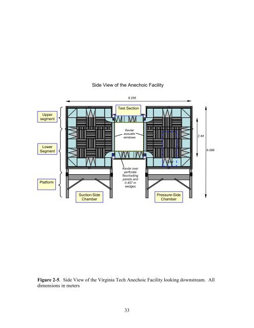
- Page 53 and 54: 5.13 m 1.83 m Acoustic Absorbers on
- Page 55 and 56: Tensioned Kevlar covering steel per
- Page 57 and 58: 2.75 1.473 0.33 0.933 1.054 2.565 D
- Page 59 and 60: Figure 2-14. Transition wedges that
- Page 61 and 62: Upper transition wedges removed flo
- Page 63 and 64: Figure 2-18. Section A-A from Figur
- Page 65 and 66: Starboard Side Window Y Z- positive
- Page 67 and 68: Figure 2-22. NACA 0012 Model mounte
- Page 69 and 70: DU97-W300 Airfoil Model Coordinates
- Page 71 and 72: Figure 2-26. Photograph of the stab
- Page 73 and 74: Figure 2-28. Boundary layer measure
- Page 75 and 76: 0.381 0.05 0.279 0.050 0.102 Figure
- Page 77 and 78: 0.03 0.02 Hard Wall Probe Calibrati
- Page 79 and 80: 5 Pitot static probes Aluminum moun
- Page 81 and 82: Figure 2-36. Wall deflection measur
- Page 83 and 84: Figure 2-38. Out of Flow microphone
- Page 85 and 86: pressure levels measured in the pro
- Page 87 and 88: The boundary layer thickness values
- Page 89 and 90: figure the negative static pressure
- Page 91 and 92: tunnel speed was increased to a nom
- Page 93 and 94: Location Number Port Starboard Cond
- Page 95 and 96: 100 Kevlar wall, 1/8-inch Mic, Midd
- Page 97 and 98: Suction Side flow 1 10 To Diffuser
- Page 99 and 100: Boundary Layer Thickness Distributi
- Page 101 and 102:
5 0.610 m NACA 0015 with Lift Inter
- Page 103 and 104:
0.16 Boundary Layer Thickness Distr
- Page 105 and 106:
0.08 0.06 Kevlar Window Shape on St
- Page 107 and 108:
Deflection,m, and CPS 0.2 0.1 0 -0.
- Page 109 and 110:
4. RESULTS OF 2007 FINAL CALIBRATIO
- Page 111 and 112:
treatment was in addition to the wa
- Page 113 and 114:
length, and lined around the circum
- Page 115 and 116:
RPM, and thus the overall drag on t
- Page 117 and 118:
These plots exclude the 10 m/s spec
- Page 119 and 120:
4.4.1 Experimental Approach During
- Page 121 and 122:
plots have the chord wise distance
- Page 123 and 124:
This confirmed that the Kevlar was
- Page 125 and 126:
thickness were computed for a nomin
- Page 127 and 128:
For the empty test section the maxi
- Page 129 and 130:
measurement. Figure 4-58 has a comp
- Page 131 and 132:
positive static pressure coefficien
- Page 133 and 134:
(2006) for one example) and the ind
- Page 135 and 136:
locations. While the power rule pla
- Page 137 and 138:
imposed by the airfoil may also be
- Page 139 and 140:
measured) for the 0.9144 m chord NA
- Page 141 and 142:
Stability Tunnel Description Power
- Page 143 and 144:
Location X Location (m) Velocity (m
- Page 145 and 146:
100 80 60 Hard Wall Baseline, 1/8-i
- Page 147 and 148:
Settling Chamber, Fan and Completed
- Page 149 and 150:
10 8 Original Vane Shape Vane shape
- Page 151 and 152:
Completed Large Wall Between 3rd an
- Page 153 and 154:
100 Completed Treatment at 10.83 m/
- Page 155 and 156:
100 Completed Treatment at 31.27 m/
- Page 157 and 158:
100 Completed Treatment at 51.45 m/
- Page 159 and 160:
100 Completed Treatment at 72.03 m/
- Page 161 and 162:
Upper Anechoic Chamber elliptic aco
- Page 163 and 164:
Model installed and removed through
- Page 165 and 166:
Steel Panel Cut Outs Kevlar coverin
- Page 167 and 168:
Figure 4-24. Photograph showing the
- Page 169 and 170:
100 80 Anechoic Configuration with
- Page 171 and 172:
100 90 80 In Flow Noise Comparison,
- Page 173 and 174:
f = 331 f f = 22 f f = 8 f f f f 10
- Page 175 and 176:
20 10 0 2007 Anechoic Configuration
- Page 177 and 178:
Narrow band SPL Anechoic Configurat
- Page 179 and 180:
0.5 NACA0012, Re= 1448757.67, α ge
- Page 181 and 182:
0.5 NACA0012, Re= 3078660.50, α ge
- Page 183 and 184:
5 4 NACA0012, Re= 1527936.46, α ge
- Page 185 and 186:
1.5 DU96, Re=1580000, α geom =3.8
- Page 187 and 188:
1.5 1 B1-18, Re=2940000, α geom =3
- Page 189 and 190:
Empty Test Section Port Window Boun
- Page 191 and 192:
Ceiling Thickness = 107 mm Port Sid
- Page 193 and 194:
Thickness of the Boundary Layer, m
- Page 195 and 196:
NACA 0012 at 8 o Effective AOA Port
- Page 197 and 198:
y-y o , cm 150 100 50 Starboard Sid
- Page 199 and 200:
Starboard Side Window at 30 m/s, NA
- Page 201 and 202:
Deflection, cm 10 5 0 -5 Suction Wi
- Page 203 and 204:
1 8 0 1 6 0 P r e s s u r e W i n d
- Page 205 and 206:
y-y o , cm 150 100 50 Suction Windo
- Page 207 and 208:
0.2 0.15 0.1 Conditions on the pres
- Page 209 and 210:
Click on plot to start streamline,
- Page 211 and 212:
Pressure Window Midheight at 30 m/s
- Page 213 and 214:
0.2 0.15 0.1 Conditions on the pres
- Page 215 and 216:
Click on plot to start streamline,
- Page 217 and 218:
Cumulative mass flux through the wi
- Page 219 and 220:
Cumulative mass flux through the wi
- Page 221 and 222:
5. CONCLUSIONS The acoustic treatme
- Page 223 and 224:
overall levels with the completed f
- Page 225 and 226:
REFERENCES 1. Brooks, T. F., Pope,
- Page 227:
21. Taylor, G., “Fluid Flow in Re