Very High Speed Counter Module - Esco Drives & Automation
Very High Speed Counter Module - Esco Drives & Automation Very High Speed Counter Module - Esco Drives & Automation
A-2 Specifications General Specifications Module Location 1734-TB, -TBS, -TB3, -TB3S wiring base assembly Keyswitch Position 2 Pointbus Current 180mA maximum Power Dissipation 1.9W maximum @ rated load Thermal Dissipation 6.5 BTU/hr maximum @ rated load Isolation Voltage (minimum) Prequalified for 1250V ac/rms between: Module 1 System side (PointBus) Chassis ground A/B/Z inputs O0/O1 and user power supply Module 2 System side Chassis ground Vaux + User power supply common External dc Power (does not represent power required to supply outputs) Field Power Bus Dimensions Inches (Millimeters) Environmental Conditions Operational Temperature Storage Temperature Relative Humidity Shock Operating Non-operating Vibration Conductors Wire Size Category Terminal Base Screw Torque No additional external power required to power module 24V dc nominal; range 10-28.8V dc 2.21H x 0.47W x 2.97L (56.0H x 12.0W x 75.5L) -20 to 55°C (-4 to 131°F) -40 to 85°C (-40 to 185°F) 5 to 95% noncondensing 30g peak acceleration, 11(±1)ms pulse width 50g peak acceleration, 11(±1)ms pulse width Tested 5g @ 10-500Hz per IEC 68-2-6 14 AWG (2.5mm 2 ) - 22 AWG (0.25mm 2 ) solid or stranded wire rated at 75°C or higher 3/64 inch (1.2mm) insulation maximum 2 2 7 pound-inches (0.6Nm) Field Wiring Terminations Module 1 0 - A 1 - Aret 2 - B 3 - Bret 4 - Z 5 - Zret 6 - Output 0 7 - Output 1 Module 2 0 - Chassis ground 1 - Chassis ground 2 - Return 0 3 - Return 1 4 - -V 5 - -V 6 - +V 7 - +V Mass 1.15 oz/32.60 grams Agency Certification (when product is marked) CE marked for all applicable directives. C-Tick marked for all applicable acts. DeviceNet compatible as certified by ODVA, Inc. 1 Off/on delay is time from a valid output “on” signal to output energization. On/off delay is time from a valid output “off” signal to output deenergization. 2 Use this conductor category information for planning conductor routing as described in publication 1770-4.1, “Industrial Automation Wiring and Grounding Guidelines.”. Publication 1734-UM003A-EN-P - August 2000
Specifications A-3 Input Derating Curve for 1734-VHSC24 30 28.8 Input Voltage Input Voltage (V) 25 24 20 15 10 5 10 20 30 40 45 55 Module Ambient Still Air Temperature (°C) Note: Exceeding the maximum input voltage can cause permanent damage to the input. Specifications for the Very High Speed Counter Module, cat. no. 1734-VHSC5 Specifications - 1734-VHSC5 Very High Speed Counter Module Input Specifications Number of Inputs 1 - 1 group of A/Areturn, B/Breturn and Z/Zreturn Input Voltage 5V dc Input Current 19.1mA @ 5V dc 25.7mA @ 6V dc Input OFF-State Current 2.6V dc Maximum ON-State Voltage +6V Input Filter Selections Off 10µs 100µs 1.0ms 10.0ms Maximum Input Frequency 1.0MHz counter and encoder X1 configurations 500kHz encoder X2 configuration (no filter) 250kHz encoder X4 configuration (no filter) Output Specifications Number of Outputs 1 isolated group of 2 capable of 0.5A @ 24V dc Output Control Outputs can be tied to any of 4 compare windows Output Supply Voltage Range 10-28.8V dc OFF-State Leakage Current
- Page 5 and 6: Preface 3 Definitions The following
- Page 7 and 8: Table of Contents Important User In
- Page 9 and 10: Chapter 1 About the Very High Speed
- Page 11 and 12: About the Very High Speed Counter M
- Page 13 and 14: About the Very High Speed Counter M
- Page 15 and 16: About the Very High Speed Counter M
- Page 17 and 18: About the Very High Speed Counter M
- Page 19 and 20: About the Very High Speed Counter M
- Page 21 and 22: About the Very High Speed Counter M
- Page 23 and 24: Chapter 2 Installing the Very High
- Page 25 and 26: 0 1 2 3 Installing the Very High Sp
- Page 27 and 28: Installing the Very High Speed Coun
- Page 29 and 30: Chapter 3 Very High Speed Counter M
- Page 31 and 32: Very High Speed Counter Module Inpu
- Page 33 and 34: Very High Speed Counter Module Inpu
- Page 35 and 36: Very High Speed Counter Module Inpu
- Page 37 and 38: Very High Speed Counter Module Inpu
- Page 39 and 40: Very High Speed Counter Module Inpu
- Page 41 and 42: Chapter 4 Configuring Your Very Hig
- Page 43 and 44: Configuring Your Very High Speed Co
- Page 45 and 46: Configuring Your Very High Speed Co
- Page 47 and 48: Configuring Your Very High Speed Co
- Page 49 and 50: Chapter 5 Accessing Instantiated In
- Page 51 and 52: Accessing Instantiated Instances 5-
- Page 53 and 54: Chapter 6 Troubleshooting with the
- Page 55: Appendix A Specifications Specifica
- Page 59 and 60: Index A active features per mode 1-
- Page 61 and 62: Allen-Bradley Publication Problem R
- Page 64: Back Cover Publication 1734-UM003A-
Specifications A-3<br />
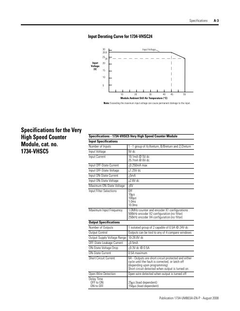
Input Derating Curve for 1734-VHSC24<br />
30<br />
28.8<br />
Input Voltage<br />
Input<br />
Voltage<br />
(V)<br />
25<br />
24<br />
20<br />
15<br />
10<br />
5<br />
10 20 30 40 45 55<br />
<strong>Module</strong> Ambient Still Air Temperature (°C)<br />
Note: Exceeding the maximum input voltage can cause permanent damage to the input.<br />
Specifications for the <strong>Very</strong><br />
<strong>High</strong> <strong>Speed</strong> <strong>Counter</strong><br />
<strong>Module</strong>, cat. no.<br />
1734-VHSC5<br />
Specifications - 1734-VHSC5 <strong>Very</strong> <strong>High</strong> <strong>Speed</strong> <strong>Counter</strong> <strong>Module</strong><br />
Input Specifications<br />
Number of Inputs<br />
1 - 1 group of A/Areturn, B/Breturn and Z/Zreturn<br />
Input Voltage<br />
5V dc<br />
Input Current<br />
19.1mA @ 5V dc<br />
25.7mA @ 6V dc<br />
Input OFF-State Current 2.6V dc<br />
Maximum ON-State Voltage +6V<br />
Input Filter Selections Off<br />
10µs<br />
100µs<br />
1.0ms<br />
10.0ms<br />
Maximum Input Frequency 1.0MHz counter and encoder X1 configurations<br />
500kHz encoder X2 configuration (no filter)<br />
250kHz encoder X4 configuration (no filter)<br />
Output Specifications<br />
Number of Outputs 1 isolated group of 2 capable of 0.5A @ 24V dc<br />
Output Control<br />
Outputs can be tied to any of 4 compare windows<br />
Output Supply Voltage Range 10-28.8V dc<br />
OFF-State Leakage Current


