Very High Speed Counter Module - Esco Drives & Automation
Very High Speed Counter Module - Esco Drives & Automation
Very High Speed Counter Module - Esco Drives & Automation
Create successful ePaper yourself
Turn your PDF publications into a flip-book with our unique Google optimized e-Paper software.
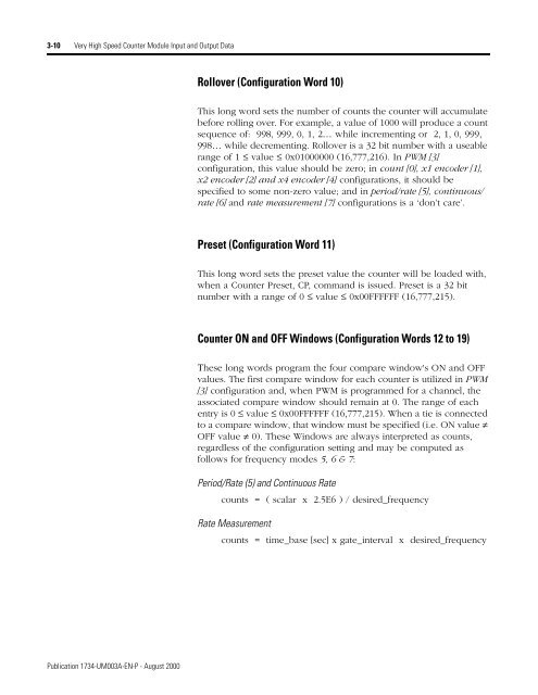
3-10 <strong>Very</strong> <strong>High</strong> <strong>Speed</strong> <strong>Counter</strong> <strong>Module</strong> Input and Output Data<br />
Rollover (Configuration Word 10)<br />
This long word sets the number of counts the counter will accumulate<br />
before rolling over. For example, a value of 1000 will produce a count<br />
sequence of: 998, 999, 0, 1, 2… while incrementing or 2, 1, 0, 999,<br />
998… while decrementing. Rollover is a 32 bit number with a useable<br />
range of 1 ≤ value ≤ 0x01000000 (16,777,216). In PWM [3]<br />
configuration, this value should be zero; in count [0], x1 encoder [1],<br />
x2 encoder [2] and x4 encoder [4] configurations, it should be<br />
specified to some non-zero value; and in period/rate [5], continuous/<br />
rate [6] and rate measurement [7] configurations is a ‘don’t care’.<br />
Preset (Configuration Word 11)<br />
This long word sets the preset value the counter will be loaded with,<br />
when a <strong>Counter</strong> Preset, CP, command is issued. Preset is a 32 bit<br />
number with a range of 0 ≤ value ≤ 0x00FFFFFF (16,777,215).<br />
<strong>Counter</strong> ON and OFF Windows (Configuration Words 12 to 19)<br />
These long words program the four compare window's ON and OFF<br />
values. The first compare window for each counter is utilized in PWM<br />
[3] configuration and, when PWM is programmed for a channel, the<br />
associated compare window should remain at 0. The range of each<br />
entry is 0 ≤ value ≤ 0x00FFFFFF (16,777,215). When a tie is connected<br />
to a compare window, that window must be specified (i.e. ON value ≠<br />
OFF value ≠ 0). These Windows are always interpreted as counts,<br />
regardless of the configuration setting and may be computed as<br />
follows for frequency modes 5, 6 & 7:<br />
Period/Rate (5) and Continuous Rate<br />
counts = ( scalar x 2.5E6 ) / desired_frequency<br />
Rate Measurement<br />
counts = time_base [sec] x gate_interval x desired_frequency<br />
Publication 1734-UM003A-EN-P - August 2000


