Worksheet Answers
Worksheet Answers
Worksheet Answers

Create successful ePaper yourself
Turn your PDF publications into a flip-book with our unique Google optimized e-Paper software.
<strong>Worksheet</strong> <strong>Answers</strong><br />
WORKSHEET 2<br />
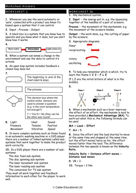
1. Whenever you see the word automatic or<br />
‘auto’, connected with a product you know it’s<br />
based upon a system that it can control.<br />
2. Input - Process - Output.<br />
3. A black box is a system that you know how to<br />
operate and you know what it does, but you don’t<br />
know how it works.<br />
4.<br />
5. When a system can sense a change in the<br />
environment and use the data to control it’s<br />
actions.<br />
6. An open loop system includes feedback a<br />
closed loop does not.<br />
7.<br />
The beginning or end of the<br />
chart (start & stop)<br />
The process<br />
WORKSHEET 3b<br />
1. Any mechanical system.<br />
2. Input – the energy put in, e.g. the squeezing<br />
together of the handles of a pair of scissors.<br />
Process – the movement of the mechanism, e.g.<br />
the movement of the scissors blades.<br />
Output – the work done, e.g. the cutting of paper<br />
by the scissors.<br />
3. Appropriate diagrams<br />
linear<br />
reciprocating<br />
rotary<br />
oscillating<br />
4. To help you remember which is which, try to<br />
learn the rhyme 1 2 3 – F L E<br />
(F L E are the initial letters of what is in the<br />
middle)<br />
5.<br />
The decision box where the<br />
control works. Sensors are<br />
used to answer a question<br />
(e.g. is the room temperature<br />
hot enough?)<br />
Y = Yes N = No (they can be<br />
the other way round)<br />
8. Light Heat Sound<br />
Pressure Tension Position<br />
Movement Vibration Speed<br />
9. In more complex systems such as those found<br />
in an automatic washing machine or a DVD player<br />
there are a number of linked systems called subsystems<br />
that work together to make the product<br />
work correctly.<br />
10. In a DVD player there are a number of subsystems:<br />
The disc feed sub-system<br />
The disc spinning sub-system<br />
The laser movement sub-system<br />
The laser reading sub-system<br />
The conversion for TV sub-system<br />
They must all work together and feedback<br />
information to each other for the player to work<br />
well.<br />
6. When a mechanism such as a lever improves<br />
the effect of an effort, the mechanism is said to<br />
have provided a Mechanical Advantage (MA). To<br />
work out what this is, the following formula can<br />
be used<br />
MA = Load ÷ Effort<br />
7. MA = 5<br />
8. Since the effort and the load started to move<br />
at the same time and stopped at the same time,<br />
but the effort moved twice as far, the effort<br />
moved faster than the load. The difference<br />
between the two speeds is known as the Velocity<br />
Ratio.<br />
Velocity Ratio = Distance effort moves ÷<br />
Distance load moves<br />
9. VR = 3<br />
10. Torque = 2 Nm<br />
© Cable Educational Ltd
<strong>Worksheet</strong> <strong>Answers</strong><br />
WORKSHEET 3d<br />
1. The load moves 2M<br />
2. The Mechanical Advantage (MA) of a pulley<br />
system is the same value as the number of pulley<br />
wheels.<br />
3. Largest load = 60N<br />
4.<br />
5. Speed ratio is<br />
Dia of driver pulley ÷ Dia of driven pulley<br />
6.<br />
WORKSHEET 4<br />
1. Frame - made up of beams connected<br />
together, e.g. Electricity pylons, some bridges,<br />
etc.<br />
Slab - made up of boards connected together,<br />
e.g. Boxes, chipboard based furniture, etc.<br />
Monocoque or Shell - made from shaped<br />
sheets of rigid material, e.g. Car bodies, cans,<br />
etc.<br />
Flexible - made from flexible sheets of<br />
material, e.g. Air beds, blow-up furniture, etc.<br />
2. Note: Most rigid structures need to be able<br />
to flex a little without breaking up, e.g. the forks<br />
on a bicycle must flex when it ridden over bumps<br />
in the road and a skyscraper must sway in a high<br />
wind.<br />
3. Tension, Compression, Bending, Torsion, Shear<br />
4.<br />
7.<br />
Gear ratio = Number of teeth on driver gear<br />
÷ Number of teeth on driven gear<br />
8. 300rpm<br />
9. Two meshing gears turn in opposite<br />
directions. To get the driver and driven gears to<br />
turn in the same direction an idler gear needs to<br />
be added to the system.<br />
10. 20rpm<br />
WORKSHEET 3e<br />
1. Cams are used in mechanisms to change<br />
rotary motion to reciprocating (backwards and<br />
forwards) motion.<br />
2.<br />
3.<br />
4. Four times faster.<br />
5.<br />
A rigid gate structure<br />
Top surface is compressed<br />
and is shorter<br />
Bottom surface is stretched<br />
and is longer<br />
WORKSHEET 5b<br />
1. Density Is the amount of matter (mass) in a<br />
material. A cube made form a high density<br />
material will be heavier than the same size cube<br />
made from a low density material.<br />
Gold & Lead<br />
2. Fusibility Is a measure of how easy it is to<br />
melt the material. The temperature at which the<br />
material normally melts is known as the melting<br />
point. Note: A highly fusible material has a low<br />
melting point.<br />
Zinc & Lead<br />
3. Wood & Polystyrene<br />
4. Copper or Gold<br />
5. There also materials like some plastics or<br />
frosted glass that let some light through, but<br />
detail of what is on the other side of the<br />
© Cable Educational Ltd
<strong>Worksheet</strong> <strong>Answers</strong><br />
WORKSHEET 5b (Cont.)<br />
material cannot be seen, these are known as<br />
Translucent materials.<br />
6. A force will deform a material. If the<br />
deformation is temporary and the material<br />
returns to its original state then it is said to be<br />
elastic.<br />
7.<br />
8. Ductility.<br />
9. Malleability Is a measure of how easily a<br />
material can be permanently deformed by<br />
compressive forces. e.g. hammering, without<br />
cracking.<br />
10. Toughness Is a measure of how well a<br />
material can stand up to sudden forces, e.g. A<br />
hammer blow, without cracking. A material that<br />
is not tough is called Brittle.<br />
WORKSHEET 7b<br />
1. When parts have to fit together.<br />
2. Incorrect measuring when using a ruler.<br />
3. A template is an accurately formed shape,<br />
made from a rigid material. The template can be<br />
drawn around or followed repeatedly without<br />
wearing away. These are particularly useful for<br />
irregular shapes.<br />
4.<br />
5. Guiding tools.<br />
Tensile strength - resists<br />
stretching e.g. High tensile steel<br />
Bending strength -<br />
resists bending - is rigid.<br />
E.g. woods<br />
Shear strength - resists<br />
sliding forces such as<br />
those made by scissors<br />
e.g. Stainless steel<br />
6. Jigs are used to ensure that dimensions are<br />
always accurate. They are particularly useful<br />
when the positioning of holes and bends are<br />
important.<br />
7. Lining up holes, bending in the correct<br />
position, lining up saw cuts, etc.<br />
8. The work piece can slip if it is not clamped in<br />
place.<br />
9. To allow the rod to be passed over the pin<br />
position, so that a reverse curve can be bent<br />
afterwards with the pin back in position.<br />
10. Mild steel.<br />
© Cable Educational Ltd<br />
WORKSHEET 8<br />
1. Computer aided design / computer aided<br />
manufacture.<br />
2. Dimensions added automatically, views can be<br />
twisted and turned and viewed from any angle.<br />
3. Faster accurate drawing, common parts can<br />
be inserted from a drawings bank, changes can<br />
be made quickly and easily, dimensions can be<br />
added automatically, printouts can be too any<br />
scale, in 3D the object can be viewed from any<br />
angle.<br />
4. The cost of the computer and programs. Early<br />
ideas can be recorded faster by sketching. A pad<br />
of paper and a pencil can be used anywhere.<br />
5. In the CAD/CAM system, data from the CAD<br />
drawing is downloaded to the CAM program<br />
which is then used to control the cutting<br />
machine.<br />
6. Injection moulding, compression moulding,<br />
vacuum forming and extrusion of plastics can all<br />
be done by computer controlled machines.<br />
7. Up to 500th of a millimetre.<br />
8. A computer can also be used to control the<br />
handling of the parts to be cut from one machine<br />
to another. Computer controlled fabrication<br />
(joining parts together) is also possible. Parts<br />
can be automatically held together in the right<br />
positions, while they are welded, riveted or glued<br />
by computer controlled equipment.<br />
9. Very accurate work The machine does need<br />
breaks The machine does not get tired and<br />
inaccurate Changes of design can be made<br />
quickly.<br />
10. The cost of the computers and programs.<br />
The high cost of the machine. The loss of jobs.<br />
WORKSHEET 9a<br />
1. One-off - Producing one product at a time.<br />
This method is often used by traditional<br />
craftsmen and artists, who work to order.<br />
2. Advantages: The customer gets a product<br />
that is designed exactly as they want it. Quality<br />
checks can be made at every stage of<br />
manufacture. Disadvantages: The production<br />
process is slow and costly.<br />
3. Batch Production - Is used where the need<br />
for a product is not continuous, or not enough<br />
are sold to make mass production worthwhile e.g.
<strong>Worksheet</strong> <strong>Answers</strong><br />
WORKSHEET 9a (Cont.)<br />
room heaters, and one style of calculator. Batch<br />
production often looks like mass production, but<br />
it uses machines that can be altered to make<br />
another model, or something completely<br />
different.<br />
4. Advantages: Flow production methods lower<br />
the production cost. Model changes can be made<br />
regularly upon change over.<br />
Disadvantages: No production occurs while the<br />
machines are being reset The products need to<br />
be stored until there is a demand for them.<br />
5. Mass Production - Is used where there is a<br />
continuous demand for large quantities of a<br />
product. E.g. Tin cans for food, cars, etc.<br />
Sometimes called flow production, this system is<br />
organised so that specially designed machines<br />
carry out one operation on the product, that is<br />
continuously passed from one different machine<br />
to the next, until at the end of the line it is<br />
complete and finished.<br />
6. Advantages: Low production costs if<br />
sufficient products are made.<br />
Disadvantages: Models cannot be changed easily.<br />
If one machine breaks down the whole line is<br />
effected. The machines cannot be easily reset to<br />
make other models. The machine cost a lot to<br />
purchase.<br />
7. Computer Integrated Manufacturing<br />
8. Stock control, production planning, marketing,<br />
sales, research and development, CAM<br />
manufacturing, quality control.<br />
9. Each department uses computers, the CIM<br />
system links all the computers, so that everyone<br />
involved can see what is happening, with regard<br />
to the product, in the other departments.<br />
10. One-off.<br />
WORKSHEET 9c<br />
1. Do what it is meant to do excellently Last a<br />
long time. Need little maintenance.<br />
2.<br />
3. The company can organise itself so that every<br />
employee tries to work with quality in mind,<br />
including those not directly involved in the<br />
making of the product, such as managers and<br />
office staff. When a company has done this they<br />
can apply to be inspected to see if they are good<br />
enough to be awarded the ISO 9001.<br />
4. To make sure the product meets the required<br />
safety standards and to maintain consumer<br />
confidence. Also to make sure that parts fit<br />
together and do not have to be rejected.<br />
5. The amount that a dimension can vary without<br />
affecting performance is known as the tolerance.<br />
6. Lengths, widths and depths. Positions of holes<br />
and their diameters. Angle measurement Surface<br />
flatness and smoothness.<br />
7. Checking each part of a product every time it<br />
is manufactured costs a lot of money and is<br />
normally only considered for the most expensive,<br />
top of the range products.<br />
8. By identifying a trend of a machine to<br />
produce out of tolerance parts, before the<br />
tolerance has been reached.<br />
9.<br />
10.<br />
© Cable Educational Ltd<br />
WORKSHEET 9d<br />
1. This analysis process involves collecting data<br />
at each stage of the manufacture and use of a<br />
product, from the extraction of the raw<br />
materials, to the problems it produces when it is<br />
thrown away at the end of its life. This data is<br />
about:<br />
A) The cost of getting the raw material.<br />
B) The cost of converting the raw material<br />
into a usable material.<br />
C) The amount of recycled material used in<br />
the product.<br />
D) How much time energy and waste is<br />
involved in the<br />
E) How much material, time and energy used in<br />
packaging.<br />
F) How easily it can be disposed of safely, or<br />
recycled.<br />
2. The aims of responsible manufacturers are:<br />
A) To reduce the amount of energy used in<br />
manufacturing the product.
<strong>Worksheet</strong> <strong>Answers</strong><br />
WORKSHEET 9d (Cont.)<br />
B) To make a product that lasts a reasonably<br />
long time.<br />
C) To make it as recyclable as possible when it<br />
is worn out, or out of date.<br />
3. Recycling is processing old material to make it<br />
good enough to be used as new. Reused refers to<br />
materials that can be used for other purposes,<br />
or products that can be cleaned and used again.<br />
4. Put in a bottle bank. Sorted for colour.<br />
Broken up. Melted down. Used as new glass or<br />
added to new glass.<br />
5. The government’s policy can be called the<br />
‘4Rs’ policy.<br />
Reduction - Reduce the production of waste in<br />
the first Place.<br />
Re-use -<br />
Recover -<br />
Remove -<br />
Clean and re-use products, e.g.<br />
Bottles.<br />
Recycle paper, glass, cloth, steel<br />
and Aluminium, etc.<br />
Remove as little as possible and try<br />
and gain energy from burning the<br />
waste or collecting methane gas<br />
from a landfill site.<br />
WORKSHEET 10a<br />
1. A new problem needs to be solved. New<br />
technology makes the old design obsolete.<br />
Fashion changes and old designs don’t sell.<br />
Novelty, a manufacturer needs their product to<br />
be different from their rivals.<br />
2. Often a company will carry out market<br />
research to see if there is a need for the<br />
product they intend to design and manufacture.<br />
One way of doing this, is by asking the general<br />
public to answer a questionnaire containing<br />
questions about the problem and what they see<br />
as a possible solution.<br />
3. :<br />
WHAT is the situation? E.g. What happens to<br />
the controllers without storage?<br />
WHY does this cause a problem?<br />
WHEN does this cause a problem? E.g. Is the<br />
user likely to be standing or sitting at the<br />
time?<br />
WHO does the problem effect? E.g. who will<br />
want to find the controllers quickly?<br />
WHERE will the solution be used? E.g. Which<br />
room and where in the room?<br />
4. A brief is a short statement explaining the<br />
problem and suggesting a possible solution.<br />
5. Analyse rival products. Investigate new<br />
technology and new materials. Check fixed data.<br />
WORKSHEET 10h<br />
1. The Designer Specification is a list of all the<br />
factors that must be right if the design is to be<br />
successful.<br />
2. Four selected from: Function, Shape, Size,<br />
Aesthetics, Storage, Manufacture, Materials,<br />
Finish, Safety, Ergonomics, Cost, Pollution,<br />
Market.<br />
3. Regularly throughout the rest of the design<br />
process.<br />
4. Isometric and Oblique.<br />
5. Crating the drawing first.<br />
6. Add notes.<br />
© Cable Educational Ltd<br />
7.Trying out small changes to your chosen idea,<br />
to improve it. Researching possible materials to<br />
use, shaping methods, jointing methods and<br />
finishes, and then choosing which you are going<br />
to use.<br />
8. Textbook or computer program.<br />
9. Weight, rigidity, hardness, toughness,<br />
texture, colour, opacity, malleability, ductility,<br />
conductivity.<br />
10. A prototype is the product made at the end<br />
of a project, using the correct sizes, materials,<br />
joints and finishes. The prototype should work. A<br />
model is often made to a proportional size, with<br />
cheaper materials. It doesn’t always need to<br />
work.<br />
11. Dimensions, proportions, colour schemes,<br />
mechanical systems, feature positions, shape,<br />
attractiveness, stability.<br />
12. Paper, card, cardboard, MDF, plywood, balsa<br />
wood, rigid foam, polymorph plastic, wire, welding<br />
rod, match sticks, lollipop sticks, clear plastic<br />
sheet, drinking straws, clay.<br />
13. Glue gun adhesive, double sided tape, split<br />
pins, blutack, PVA, velcro, pritt-stick.<br />
14. Orthographic working drawing Rendered<br />
pictorial drawing<br />
15. It should include all the information<br />
required to make the product.<br />
16. Information table Flowchart.<br />
17. The ‘Quality Check’ column is very important,<br />
because if the checks are not planned they will<br />
be forgotten and the product parts are unlikely<br />
to fit together well.<br />
18. Drilling holes before the item is bent and<br />
difficult to hold.
<strong>Worksheet</strong> <strong>Answers</strong><br />
WORKSHEET 10h (Cont.)<br />
19. Designer specification.<br />
20. Market Testing To support your own<br />
thoughts about the product, it is a good idea to<br />
create a questionnaire and ask your family and<br />
friends to give their opinions by testing your<br />
prototype.<br />
WORKSHEET 11a<br />
1. One year’s growth of wood is shown as an<br />
annual ring.<br />
2. By counting the number of annual rings.<br />
3. The five main features are: bark, growth<br />
cells, annual rings, heartwood, sapwood.<br />
4. Harder, darker and drier, the best wood.<br />
5. To be useful, the wood has to be converted<br />
from a tree trunk to planks. This is done by<br />
sawing through the tree trunk. There are two<br />
common methods of sawing.<br />
6.<br />
WORKSHEET 11c<br />
1. Hardwoods - deciduous. Softwoods -<br />
coniferous.<br />
2. Made from the waste wood left over from<br />
conversion.<br />
3. Planed All Round, Planed Both Sides.<br />
4. 47mm x 22mm<br />
5. A plank is between 225 and 375mm wide and<br />
50mm or more thick. A strip is between 25 and<br />
100mm wide and between 9 and 25mm thick.<br />
6. Cedar or protected Scots Pine.<br />
7. Beech<br />
8. It is made from thin sheets of wood<br />
(veneers), glued together with the grain<br />
direction at 90° to the one next to it. They<br />
always have an odd number of layers 3,5,7 etc. to<br />
reduce warping.<br />
9. Blockboard<br />
10. It is made from small chips of waste wood.<br />
Through and through<br />
Conversion<br />
Quarter sawn<br />
Conversion<br />
Through and through - a quick cheap method,<br />
but produces planks that are likely to warp.<br />
Quarter Sawn - a more costly method that<br />
produces more waste, but the planks produced<br />
are less likely to warp.<br />
7. When the wood is cut into planks it is still<br />
very wet from the water taking the minerals<br />
from the roots to the leaves. If the planks dry<br />
quickly the wood splits and warps and becomes<br />
useless. To dry the wood slowly it is stacked in<br />
large drying ovens called kilns. The drying<br />
programme takes four or five weeks.<br />
8.<br />
9. Less than 10%<br />
10. It is best stored flat or vertically upright,<br />
so that it does not bend because of its own<br />
weight.<br />
WORKSHEET 12<br />
1.<br />
1. Look along the length of the strip of wood<br />
and see if it is warped, bowed or twisted.<br />
2. Check the ends to see if there are any<br />
splits.<br />
3. Check for knot holes or loose knots.<br />
4. Check to see if there are too many knots,<br />
because they may make the wood hard to<br />
plane smooth.<br />
5. Check for small holes made by insects<br />
such as woodworm.<br />
2. 3mm<br />
3. Allow 1162mm or 1165mm (3mm added at one<br />
end or both ends).<br />
4. Marking gauge.<br />
5. Check that the edge is at right angles with a<br />
try square.<br />
WORKSHEET 13<br />
1. Mark out the shape in a corner of the sheet.<br />
2. By the loop mark on the face side and the tick<br />
mark on the face edge.<br />
3.<br />
© Cable Educational Ltd
<strong>Worksheet</strong> <strong>Answers</strong><br />
WORKSHEET 13 (Cont.)<br />
4. With the handle touching the face edge.<br />
5. A marking gauge.<br />
6. It cannot be rubbed out.<br />
7. Dividers have points on both legs.<br />
8. A marking knife.<br />
WORKSHEET 14a<br />
1. Each tooth of the saw is alternately bent to<br />
the right and the left of centre. This is to stop<br />
the blade from jamming in the cut. The width of<br />
the cut is called the kerf.<br />
2. Diagram of a bench hook (sawing board).<br />
3. Use trestles (sawing horses)<br />
4. A Tenon Saw, it has a rigid blade designed for<br />
cutting joints.<br />
5. A Panel Saw, because you can complete long<br />
straight cuts with it.<br />
6. Coping Saw<br />
7. Teeth per inch.<br />
8. Set the frame at right angles to the blade.<br />
WORKSHEET 14c<br />
1. Jack plane and Smoothing plane.<br />
2. So that the plane produces tissue thin<br />
shavings.<br />
3. Height adjustment screw.<br />
4. Level adjustment lever.<br />
5. 0.5mm or less.<br />
6.To check the direction, the side of the piece<br />
of wood should be looked at, not the top surface<br />
being planed. Look at the grain approaching the<br />
top surface. Plane in the same direction.<br />
7. Either direction.<br />
8. The wood splits.<br />
9. Plane half way from both ends.<br />
10. Clamp an extra piece of waste wood to the<br />
edge of the board or chamfer the corners of the<br />
board.<br />
WORKSHEET 14d<br />
1.<br />
2. Ash or Polycarbonate<br />
3. It stops the wooden handle from splitting.<br />
4. They allow the chisel to get into corners.<br />
5. Keep both hands behind the blade.<br />
6. Tool steel<br />
7. For cutting the mortise of a mortise and<br />
tenon joint.<br />
8. To absorb some of the shock.<br />
9. The gouge has a curved blade the firmer<br />
chisel has a flat blade.<br />
10. To cut shallow depressions in wood.<br />
WORKSHEET 14e<br />
1. Holding the drill bit.<br />
2. HSS High Speed Steel.<br />
3. Countersunk hole Screwhead level with surface<br />
4.<br />
5. This drill is so named because the main parts<br />
can be made to slide up and down the central<br />
pillar.<br />
6. When drilling a larger hole with a power drill.<br />
7. When using a flatbit or hole saw, only cut the<br />
hole until the point of the flatbit, or the guide<br />
bit of the hole saw, break through the other<br />
side. Then turn the wood over and using the<br />
break-through hole as a guide, cut the second<br />
half of the hole.<br />
8. Hole saw. Drill bits are not normally made<br />
that large.<br />
© Cable Educational Ltd
<strong>Worksheet</strong> <strong>Answers</strong><br />
WORKSHEET 14f<br />
1. Never use a power tool until you have<br />
received instruction on how to use it safely.<br />
2. If your finger touches the revolving disc you<br />
will receive a very painful graze.<br />
3. A good rule is that when the wood is touching<br />
the disc it should be covering the slide slot in<br />
the table. If it doesn’t, it is too short.<br />
4. To stop the disc from clogging.<br />
5. If a finger touches the blade lightly, the<br />
flesh tends to move up and down with the blade<br />
and is not cut by it.<br />
6. Position the hold down bar no more than<br />
0.5mm above the material being cut.<br />
7. Stop the power lead from trailing across the<br />
floor of the workshop.<br />
WORKSHEET 15c<br />
1. Side grain to side grain.<br />
2. A butt joint is end grain to side grain, a cut<br />
joint allows for side grain to side grain contact.<br />
3. Two from: butt joint, lap joint, comb joint,<br />
mitre joint, dowel joint, dovetail joint. Both<br />
sketched.<br />
4. Two from: through housing, dovetail housing,<br />
stopped housing. Both sketched.<br />
5. A wooden strip glued on the inside or dovetail<br />
pinning. (Sketched)<br />
6. Triangular pieces of thin wood glued into saw<br />
cuts across the joint. (Sketched)<br />
7. Lining up the holes.<br />
8. Dovetail joint. (Sketched)<br />
9. Use a Cross halving.<br />
10. One from through housing, dovetail housing,<br />
or stopped housing. (Sketched).<br />
4. The glue soaks into the pores of the wood and<br />
then sets like lots of little fingers grabbing onto<br />
the wood on both sides.<br />
5. It is very important that the surfaces to be<br />
glued are freshly cleaned with glass paper to<br />
remove any dirt or oily residue left by touching<br />
the surface with your fingers.<br />
6. Using a cramp to hold the two halves of a<br />
joint together firmly, helps to force glue into<br />
the pores of the wood. Cramping also holds the<br />
joint still while the glue is setting.<br />
7. Varnish the wood before you glue the parts<br />
together, the glue will not stain varnished wood.<br />
8. After normal glueing, mix sawdust of the<br />
same wood with the glue to make a paste and use<br />
this to fill the gap.<br />
9. Synthetic Resin (Cascamite) because it is<br />
waterproof.<br />
10. Use it in a well ventilated area and do not<br />
sniff it.<br />
WORKSHEET 18b<br />
1. Friction between the nail shaft and the<br />
surrounding wood.<br />
2. Galvanised mild steel.<br />
3. A pin punch is used with a hammer to drive<br />
the head of the pin below the wood surface. The<br />
hole above the pin head can then be filled with a<br />
wood.<br />
4. Place the nail at least nine times its diameter<br />
from the end of the wood.<br />
5. Sketch of claw hammer. Designed for hitting<br />
nails into wood and for removing bent nails from<br />
wood.<br />
6. Hold the pin in a piece of card.<br />
7. The chipboard screw has thread all the way<br />
up the shaft and it has two threads (spirals)<br />
wrapped around each other.<br />
8.<br />
WORKSHEET 17<br />
1. Permanent jointing.<br />
2.The solvent needs to evaporate (dry) before<br />
the adhesive works. The time this takes is called<br />
the setting time.<br />
3. Most wood adhesives are made up of solid<br />
particles of glue being dissolved in a solvent<br />
(water or spirit).<br />
9.<br />
10. Knock down joint.<br />
© Cable Educational Ltd
<strong>Worksheet</strong> <strong>Answers</strong><br />
WORKSHEET 19<br />
1. A laminate is made up of layers of veneers<br />
(thin sheets of natural wood) glued, one on top of<br />
another. Unlike plywood, the grain of each sheet<br />
is normally lined up in the same direction.<br />
2. For laminated wood to bend the layers would<br />
need to slide over each other the adhesive<br />
prevents this from happening.<br />
3. A laminated strip is tougher than solid wood<br />
because a crack that starts on one side of the<br />
strip is stopped by the glue line and does not go<br />
all the way through.<br />
4.<br />
5.<br />
6. To stop the laminate from sticking to the<br />
blocks.<br />
WORKSHEET 20b<br />
1. To stop wood from absorbing moisture, so<br />
that it is less likely to become stained and warp.<br />
To protect against rot and insect attack. To<br />
improve the appearance of the wood’s surface.<br />
2. Planing with the blade set to provide tissuethin<br />
shavings.<br />
3. 00<br />
4. Wrap the glasspaper around a sanding block.<br />
Always sand backwards and forwards in the<br />
direction of the grain.<br />
5. Stain (colouring) is used to change the colour<br />
of light woods to make them more interesting or<br />
to blend in with darker woods.<br />
6. Matt, satin and gloss.<br />
7.<br />
i) Apply the first coat thinly and let it set<br />
fully. This coat soaks into the pores of the<br />
wood and then sets. The wood is now sealed.<br />
ii) Use a fine grade of glass paper to lightly<br />
sand the surface because the first coat<br />
tends to make the surface rough as it sets.<br />
iii) Apply the second coat also thinly, check<br />
for any runs or drips and let it set to a<br />
smooth finish.<br />
8. It does not crack or peel off.<br />
9.<br />
1. A primer coat. A primer is a paint that<br />
sets quickly and seals the pores in the wood.<br />
2. An undercoat coat. Undercoat paint<br />
contains a lot of pigment (colour) to stop the<br />
original surface showing through.<br />
3. A gloss top coat. Gloss paint contains less<br />
pigment and more clear varnish to provide<br />
the shine. If the paint also contains<br />
polyurethane it will have a tough, scratch<br />
resistant finish.<br />
10. Acrylic gloss. A water based paint that only<br />
requires a primer and top coat. The gloss is not<br />
as shiny, or the finish as scratch resistant as a<br />
polyurethane paint. Emulsion A water based paint<br />
that often contains vinyl to make it more water<br />
resistant and easier to wipe clean. Normally only<br />
two coats are required, the first coat seals the<br />
wood like a primer. The finish can be matt or<br />
satin only, gloss is not an option.<br />
WORKSHEET 21<br />
1.<br />
© Cable Educational Ltd<br />
2. So that they can be held safely and give good<br />
leverage.<br />
3. It is cut into an octagonal shape.<br />
4. The outside shape before the hollowing.<br />
5. The wood should be prepared by marking out
<strong>Worksheet</strong> <strong>Answers</strong><br />
WORKSHEET 21 (Cont.)<br />
an octagon on both ends and then planing the<br />
sides. At one end a saw cut should be made to<br />
allow the teeth of the drive dog to dig into the<br />
wood. (sketches req.).<br />
6.<br />
7.<br />
10. It is weak and soft.<br />
WORKSHEET 25<br />
1. Scribers, scribing blocks, dividers and odd-leg<br />
callipers.<br />
2. Using Engineer’s Blue<br />
3. Use a centre punch to make an indent for the<br />
leg to sit in.<br />
4. Odd-leg Callipers.<br />
5. For running along the edge of the metal.<br />
6. So lines can be scratched at different<br />
heights.<br />
7. Because it can do at least three different<br />
jobs.<br />
8.<br />
8. Never attempt to use a lathe until you have<br />
received instruction from your teacher. Always<br />
wear goggles!<br />
9.<br />
WORKSHEET 24b<br />
1. Ferrous - metals that contain iron and are<br />
affected by magnetism (apart from stainless<br />
steel).<br />
Non-ferrous - metals that do not contain iron<br />
and are not effected by magnetism.<br />
2. Alloys - metals made up from a mixture of<br />
elements, e.g. Copper + zinc (brass) or lead + tin<br />
(solder)<br />
3. In steel the rust layer is loose and can fall<br />
away; this exposes new atoms that will combine<br />
with oxygen to form new rust. In non-ferrous<br />
metals the oxide layer is dense and does not fall<br />
away; this creates a barrier to the oxygen in the<br />
air and new corrosion occurs very slowly. The<br />
layer is called tarnish.<br />
4. Mild steel contains contains 0.15 - 0.35%<br />
carbon, and is ductile, malleable and tough. Tool<br />
steel contains 0.8 - 1.5% carbon, and is very<br />
hard, rather brittle and is difficult to cut.<br />
5. It does not rust.<br />
6. It is nearly as strong as mild steel but only<br />
only third the weight.<br />
7. It is a good conductor of heat and has a high<br />
melting point.<br />
8. It is not rigid enough to be used for taps.<br />
9. It is wear resistant.<br />
10. A sketch showing the combination square set<br />
up like an engineers square.<br />
WORKSHEET 26a<br />
1. To take different lengths of blade.<br />
2. 32 TPI or 24 TPI<br />
3. So that the teeth don’t jam.<br />
4.<br />
5. A Tension file.<br />
6.<br />
7.<br />
© Cable Educational Ltd<br />
8. To stop the saw blade from sliding over the<br />
metal when starting a cut, use a triangular file to<br />
file a groove on the waste side of the line. The<br />
saw teeth should fit into the groove.
<strong>Worksheet</strong> <strong>Answers</strong><br />
WORKSHEET 26b<br />
1. To push fit into the handle.<br />
2. Sketches of cross sections of flat, square,<br />
triangular, round, half-round, knife.<br />
3. Bastard to get rid of most of the waste<br />
quickly. Second cut to leave a reasonably smooth<br />
finish. Smooth or dead smooth to provide a very<br />
smooth finish.<br />
4.<br />
the vice can be used as a guide.<br />
5. When cutting along a curved line.<br />
6. One side of the cut curves away from the<br />
other side.<br />
7. They can be used for both straight and<br />
curved cuts.<br />
WORKSHEET 26e<br />
1.<br />
5. When filing a long edge, push the file<br />
forwards and slide it sideways at the same time.<br />
6. Drawfiling (Sketched)<br />
WORKSHEET 26c<br />
1. To hold smaller diameter jobber drill bits.<br />
2. The larger diameter bits have a tapered<br />
shank and are held directly in the pillar drill<br />
spindle. The thin part at the end locks into the<br />
spindle and cannot slip under pressure, like a<br />
straight shank could in a chuck.<br />
3. For holes in metal of 8mm diameter or larger,<br />
it is better to use a smaller drill bit first (4 or<br />
5mm dia.). The smaller drill is less likely to<br />
wander off the centre punch mark. It also<br />
provides a hole that can guide (pilot) the larger<br />
drill.<br />
4. Set the pillar drill’s depth stop, so that the<br />
drill cannot drill beyond a depth of 10mm.<br />
5. Use cone bit.<br />
6. Illustration of a hand vice with the metal<br />
supported on a block of wood.<br />
WORKSHEET 26d<br />
1. High Carbon Steel<br />
2. A sketch of chain drilled holes.<br />
3. The chisel is hit with a hammer to cut<br />
between the holes until the inside is cut free.<br />
The edges are then filed with a safe-edge file.<br />
2. HSS or tool steel with a tungsten carbide tip.<br />
3. To 100th of a millimetre.<br />
4. Illustration of turning down, facing off,<br />
parting off, thread cutting.<br />
5. Enlarging a hole by cutting away the inside<br />
wall.<br />
6. The chuck revolves the work, while the drill<br />
bit is held still in the tailstock.<br />
7. Use a centre drill.<br />
WORKSHEET 27a<br />
1. Annealing - by heating the metal to a dull red.<br />
The metal is now more malleable, so it will not<br />
split when it is hit with the mallet. The surface<br />
will now be black (burnt tarnish) and this needs<br />
to be cleaned off before hollowing. Either emery<br />
cloth can be used to clean it, or the still warm<br />
disc can be placed into a bath of dilute sulphuric<br />
acid.<br />
2. Forming block or sandbag and a bossing<br />
mallet.<br />
3.<br />
4. Chiselling is faster than filing and the top of<br />
© Cable Educational Ltd<br />
4. Sinking gives a lip around the edge.<br />
5. Sketches of a bowl without a lip and one with<br />
a lip.
<strong>Worksheet</strong> <strong>Answers</strong><br />
WORKSHEET 27a (Cont.)<br />
6. a) to remove any unwanted bumps and to<br />
correct the overall shape.<br />
b) to harden the metal and make it more rigid.<br />
7. The bowl is placed over a Mushroom Stake.<br />
Starting in the centre, the bowl is revolved one<br />
space after each blow. The blows should spiral<br />
outwards to the edge.<br />
3. To grip the hot metal firmly.<br />
4.<br />
WORKSHEET 27b<br />
1. Up to 1.5 mm.<br />
2. The net should be dimensioned for a box of<br />
200x150x20mm.<br />
5.<br />
1. Hold the bar at a slight<br />
angle to the anvil face and<br />
hit on one side, the anvil<br />
face flattens the other<br />
side at the same time.<br />
2. Turn the bar 90°<br />
and hit again to make<br />
the point square in<br />
shape.<br />
3. It is less costly than metal if an error is<br />
made.<br />
4. By folding over to make a safe edge.<br />
5. Folding bars can handle sheet metal of larger<br />
size than a vice on its own.<br />
6. By using a block of wood a folding jig. It has<br />
to be the same size as the base but thicker than<br />
the box height.<br />
7. Use wooden striker, hit with a mallet.<br />
8. For bending curves, a machine that has three<br />
adjustable rollers is used. The tightness of the<br />
curve can be controlled by altering the position<br />
of each roller.<br />
WORKSHEET 27d<br />
3. Hit each corner of the<br />
square shape to turn it<br />
into an octagonal shape<br />
4. Continue turning<br />
the bar and hitting the<br />
corners until the point<br />
is round in shape.<br />
6. Upsetting is the term given to the process of<br />
thickening the metal. This is useful for<br />
maintaining strength when drilling a hole.<br />
7. Heat the bar to a bright red and then grip it<br />
the vice and slide on a special twisting tool, or<br />
use a large tap wrench. Twist the metal while it<br />
is still red hot. Twisting will only occur between<br />
the vice and the wrench.<br />
1. When it is hit it is squashed and becomes<br />
denser. Also, a shaped product will have the<br />
‘grain’ (layers of crystals) flow around the shape.<br />
2.<br />
© Cable Educational Ltd
<strong>Worksheet</strong> <strong>Answers</strong><br />
WORKSHEET 27d (Cont.)<br />
8.<br />
2. Work towards the end of<br />
the metal to complete the<br />
curving.<br />
9.<br />
An ‘S’ scroll<br />
1. Start the curve by<br />
hammering it over the anvil<br />
beak.<br />
3. Close the loop by tapping it with<br />
a hammer on top of the anvil face.<br />
10. The metal is heated to bright red in a forge.<br />
WORKSHEET 28b<br />
1. The pattern should be tapered so that it can<br />
be taken out of the sand without dislodging any<br />
sand grains. The taper is known as the Draft.<br />
2. Internal corners need to have a fillet to stop<br />
cracks appearing during cooling.<br />
3. A pattern that, because of its shape, would<br />
dislodge sand when it was removed needs to be<br />
split into two or more sections. The two halves<br />
are held together with dowels.<br />
4. So that the halves can be separated when the<br />
pattern needs to be removed.<br />
5. A) the drag is turned upside down and put on<br />
the base board. The pattern is placed in the<br />
middle. Moulding sand, made damp with oil or<br />
water is sieved over the pattern until the<br />
pattern is covered. B) The rest of the sand is<br />
then shovelled in and then rammed with a<br />
rammer until it is packed tightly. The surface is<br />
then levelled by scraping a metal strip across<br />
(strickling).<br />
C) The drag is turned the right way up and the<br />
cope is then placed on top. The top half of the<br />
pattern is added and also the sprue pins are<br />
positioned. Sand is then added and rammed to fill<br />
the cope.<br />
D) The cope is now lifted off and the top half of<br />
the pattern and the sprue pins are removed.<br />
Channels called gates are cut between the sprue<br />
pin holes and the pattern to allow the molten<br />
metal to flow into the mould cavity.<br />
E) A wood screw is screwed into the pattern and<br />
it is tapped from side to side to release the<br />
pattern from the sides of the sand mould. The<br />
pattern is then carefully lifted vertically from<br />
the mould.<br />
F) The cope is placed back on the drag. A hollow<br />
basin shape (pouring basin) is cut into the sprue<br />
hole that the metal will flow into (runner). A thin<br />
metal rod is pushed into the sand to create<br />
narrow holes that will allow air to escape when<br />
the metal is poured.<br />
6. To allow trapped air to escape.<br />
7. The casting will come free with its gates and<br />
sprues attached, these will have to be removed<br />
by sawing them off and filing down the stumps.<br />
8. To provide a hole in the casting.<br />
9. Extra pieces are added to provide hollows in<br />
the mould that will hold the core in place. These<br />
are called core prints.<br />
10. The cores sit in the core prints.<br />
WORKSHEET 29b<br />
1. Cutting an internal thread into the side of a<br />
hole is known as ‘tapping the hole’.<br />
2. On a tap or die. The ‘M’ stands for metric.<br />
The 10 is the thread diameter in mm. The 1.5 is<br />
the size of the pitch in mm.<br />
3. The pitch is the distance between the tip of<br />
one tooth and the tip of the next tooth, in mm.<br />
4. This is a hole that is smaller in diameter than<br />
the thread diameter (nominal size), so that the<br />
thread can be cut into its side.<br />
5. A blind hole.<br />
© Cable Educational Ltd<br />
6. Taper tap - tapers for ten threads. Second<br />
tap - tapers for five threads. Plug tap - tapers<br />
for 1.25 threads.
<strong>Worksheet</strong> <strong>Answers</strong><br />
WORKSHEET 29b (Cont.)<br />
7.<br />
8. A die held in a die stock.<br />
9. The centre screw is tightened to open the<br />
die. The outer screws are tightened to close the<br />
die.<br />
10. Make sure that the die stock is at right<br />
angles to the rod to stop a ‘drunken’ thread being<br />
cut.<br />
Effect of drunken thread<br />
WORKSHEET 29c<br />
1. Hammer the rivet shank into a rough<br />
mushroom shape using the Ball Peen part of the<br />
hammer head.<br />
2. The set part is used to go over the shank of<br />
the rivet and push the two pieces of metal to be<br />
joined together. The snap part is used to support<br />
the rivet head while the shank is being formed<br />
and also to round off and smooth the rough<br />
shaped head at the shank end.<br />
3. To make sure the holes line up, mark out and<br />
drill one pair of holes only. Rivet them together<br />
and then line up the metal sheets. The remaining<br />
holes can then be marked out and drilled.<br />
4. The pin is pulled by jaws in the gun. The pin<br />
head squeezes into the tube of the rivet. The pin<br />
then breaks away and leaves the head behind.<br />
soaking into the surface of the metals to be<br />
joined.<br />
4. To stop the component form overheating. The<br />
heat goes into the sink to heat it up instead of<br />
travelling further up the wire and heating the<br />
component.<br />
5. The solder remains liquid until the surface<br />
goes dull.<br />
6.<br />
1. When the metal is heated up for soldering<br />
it stops an oxide layer forming (tarnish).<br />
Molten solder must be able to soak into the<br />
surfaces of the metal sheets being joined, to<br />
make a strong joint.<br />
2. It breaks down the surface tension of the<br />
molten solder to allow it flow in between the<br />
metal sheets.<br />
7. Acid - a clear liquid that when applied will<br />
clean the surface of the sheet metal by<br />
dissolving any oxide layer or grease, before<br />
soldering starts. This flux must be washed away<br />
with water as soon as the joint has been<br />
soldered, otherwise it will weaken the joint.<br />
Passive - a brown resin that looks like grease.<br />
This does not dissolve any old oxide layers, so<br />
surfaces need to be cleaned with emery cloth<br />
first. It does not need to be washed away at the<br />
end.<br />
8.<br />
1. Apply flux to both 2. Melt solder onto<br />
the surfaces<br />
hot tip (tinning the<br />
iron)<br />
3. Apply solder to<br />
both fluxed<br />
surfaces<br />
4. Place the parts together<br />
and rub the hot iron over<br />
the joint to re-melt the<br />
solder. Then let it cool and<br />
set.<br />
WORKSHEET 29d<br />
1. Tin and Lead.<br />
2. 183° to 250°C<br />
3. Dirt and grease will stop the solder from<br />
© Cable Educational Ltd
<strong>Worksheet</strong> <strong>Answers</strong><br />
WORKSHEET 29e<br />
1. Spelter is brass (copper & zinc) and melts at<br />
870°C.<br />
2. The force of the blowtorch flame can move<br />
the metal parts to be soldered.<br />
3. So that the loops can be twisted to tighten<br />
the wire.<br />
4. Borax. The powder is mixed with water to<br />
make a paste.<br />
5.<br />
6. Copper, zinc and silver.<br />
7. Easy flow - melts between 625°C and 690°C<br />
Medium - melts between 690°C and 725°C Hard<br />
- melts between 725°C and 800°C<br />
8. If one type of solder only was used, then the<br />
solder put on the seam would re-melt and the<br />
joint would spring open when the base was being<br />
heated for joining. When the three grades are<br />
used, as shown in the diagram, each joint melts<br />
at a lower temperature than the last, so earlier<br />
joints stay set.<br />
WORKSHEET 29f<br />
1. Gas - using an oxyacetylene gas flame Arc -<br />
using an electric spark Resistance - using an<br />
electric current.<br />
2. Acetylene and Oxygen.<br />
3. The filler rod is used to build up the joint and<br />
to replace the metal that has evaporated.<br />
4. The flame is moved forward in a series of<br />
small circular movements to heat a wider area<br />
than the diameter of the flame.<br />
5. If the ends are not tacked the pieces will<br />
warp in the heat and the joint will separate.<br />
6. The joint metal and the filler rod are both<br />
connected to an electric circuit. When the rod is<br />
held a short distance away from the joint, sparks<br />
fly between the two. The temperature of the<br />
sparks is so high that both the end of the rod<br />
and the joint metal melt and form a weld pool.<br />
7. A passing a current through the sheets of<br />
metal heats them up where they touch each<br />
other, because this is where there is most<br />
resistance.<br />
8. Illustration of Squeeze time, Weld time, Hold<br />
time and Release.<br />
WORKSHEET 30<br />
1. Work Hardening When metal is bent or<br />
shaped by hitting with a mallet, the area being<br />
reshaped becomes harder and more brittle.<br />
2. Annealing is the process of heating metal to<br />
soften it and remove the brittleness.<br />
3. Put soap on the surface and heat with a<br />
blowtorch until the soap turns black.<br />
4. Heat to cherry red and then let it cool slowly,<br />
buried in sand.<br />
5. It is hardened by heating to bright red and<br />
then cooling it quickly by plunging it into room<br />
temperature water.<br />
6. It is now very hard, but unfortunately also<br />
very brittle, too brittle to use without it<br />
breaking. It needs to be softened a little to<br />
reduce the brittleness, this is done by the<br />
process of tempering.<br />
7. A) Clean the area to be tempered. B) Heat<br />
gently until the correct colour appears and moves<br />
to the blade. C) Plunge into room temperature<br />
water and swirl it around.<br />
8. It is case hardened.<br />
9. Any cracks that start in the hard, brittle<br />
outer case are stopped by the soft core.<br />
10. At certain temperatures, colours appear on<br />
the surface that only appear at that particular<br />
temperature. So the type of colour showing tells<br />
you what the temperature of the surface is.<br />
© Cable Educational Ltd
<strong>Worksheet</strong> <strong>Answers</strong><br />
WORKSHEET 31<br />
1. Wrap emery cloth around a file and rub it up<br />
and down in one direction.<br />
2. It can catch your clothing or a rag if you are<br />
holding it and drag your hand into the machine.<br />
3. It is less likely to flake off.<br />
4. Lacquered.<br />
5.<br />
6. Enamelling.<br />
Blown air<br />
WORKSHEET 32b<br />
1. Piercing is when a press is used to cut holes<br />
of any shape out of a sheet of metal. The part<br />
cut out is waste. Blanking is when a press is used<br />
to cut out a shape that is to be kept and used.<br />
The sheet of metal that it has been cut from is<br />
the waste.<br />
2.<br />
3.<br />
4. Illustrations of extrusion and rolling.<br />
5. An ingot of metal is heated until it is soft. A<br />
hydraulic ram then forces the metal through a<br />
shaped hole in a die.<br />
6. Die casting. Because the moulds are<br />
permanent and do not need to be made each<br />
time.<br />
7. Lost wax casting.<br />
WORKSHEET 33<br />
1. Thermoplastics - can be reshaped by heating.<br />
They will try and return to their original shape if<br />
re-heated. Thermosetting Plastics - cannot be<br />
reshaped by heating and can withstand higher<br />
temperatures than thermoplastics.<br />
2. All modern plastics are made mainly from oil,<br />
coal and extracts from plants. They are<br />
synthetic (not natural - manmade) and come in<br />
hundreds of types, each with their own set of<br />
properties. Many have been made to order by<br />
materials scientists.<br />
3. Most property changes are made by adding<br />
additives to the basic plastic.<br />
4. To protect it from the effects of ultra violet<br />
light and stop it becoming brittle.<br />
5. Polyvinyl chloride (PVC) because it is rigid,<br />
quite hard, has good chemical resistance and is<br />
tough.<br />
6. Expanded polystyrene because it is very light<br />
in weight.<br />
7. Acrylic, because it is rigid, hard, very durable<br />
outside and polishes to a high shine.<br />
8. It is tough, resists wear, has good chemical<br />
resistance.<br />
9. ABS because it is very tough, scratch<br />
resistant and has good chemical resistance.<br />
10. Urea formaldehyde, because it is rigid, hard,<br />
strong, heat resistant, does not bend when<br />
heated.<br />
WORKSHEET 34<br />
1. To protect the surfaces from accidental<br />
scratching.<br />
2. Spirit based markers.<br />
3. By marking out the centre point on a double<br />
layer of masking tape stuck in the correct<br />
position.<br />
4. To allow a pencil to be used for marking out a<br />
curved line and a marking gauge to scratch a line.<br />
5. Show that there is less waste when a shape is<br />
marked out in a corner and not in the centre of a<br />
sheet.<br />
WORKSHEET 35a<br />
1.<br />
1. Hard, rigid plastics such as Acrylic and<br />
Polystyrene can crack easily if they are not<br />
well supported.<br />
2. Power saws tend to create so much<br />
© Cable Educational Ltd
<strong>Worksheet</strong> <strong>Answers</strong><br />
WORKSHEET 35a (Cont.)<br />
friction heat that the cut plastic softens<br />
and welds itself back together again behind<br />
the blade.<br />
2. It provides support all around the saw blade.<br />
3. If the teeth pointed upwards the plastic<br />
would rise with saw with no support.<br />
4. The tape takes away enough heat from the<br />
plastic to stop it welding together behind the<br />
blade.<br />
5.<br />
sheet of MDF. Let it cool. C) Remove the top<br />
surface to half the depth of the indent with a<br />
file. D) Re-heat in an oven until the acrylic<br />
returns to its original thickness.<br />
4. A description of press forming.<br />
5. So that the formed plastic can be removed<br />
from the mould easily.<br />
6.<br />
6.<br />
7. A standard drill will catch the plastic as it<br />
breaks through the bottom of the hole and cause<br />
cracking around the hole.<br />
8. Use pilot holes. First drill the hole with a<br />
4mm drill and then redrill with a 6mm drill and<br />
continue using drills that are 2 or 3mm larger in<br />
diameter until the correct size is reached.<br />
WORKSHEET 35c<br />
1. If the plastic sheet is re-heated then it will<br />
try to return to its original shape of a flat sheet.<br />
This property is known as plastic memory.<br />
2.<br />
7. Using a profile router.<br />
8. Blow moulding, Vacuum forming, Press<br />
forming.<br />
9. Blow moulding.<br />
WORKSHEET 35d<br />
1. Injection moulding (possible diagram)<br />
2. Thermoset plastics cannot be softened by reheating,<br />
so any plastic left in the machine would<br />
block the nozzle for good.<br />
3.<br />
3. A) Placing a shape onto MDF. B) Clamp a sheet<br />
of soft heated acrylic between the shape and<br />
4. A) A layer of release agent is applied to the<br />
© Cable Educational Ltd
<strong>Worksheet</strong> <strong>Answers</strong><br />
WORKSHEET 35d (Cont.)<br />
inner surface to stop the new GRP from sticking<br />
to the mould. The release agent can be in wax<br />
form.<br />
B) A thick layer of coloured gellcoat resin is<br />
painted over the release agent.<br />
C) A sheet of glassfibre is laid by hand over the<br />
dry but sticky gell coat layer.<br />
D) Polyester resin, the same colour as the<br />
geelcoat, is stippled onto the glassfibre until it is<br />
covered with resin. This is then allowed to set<br />
before the hull is taken out of the mould.<br />
WORKSHEET 36<br />
1. A diagram of an ‘Octaclip’ in use.<br />
2. Any cement spillage or seepage from the joint<br />
will permanently mark the surface.<br />
3. Cements are spirit based and can cause major<br />
problems if sniffed.<br />
4. Where large areas of contact are involved.<br />
5. A heated wheel, run over two sheets, one on<br />
top of the other, will heat-weld the two sheets<br />
together along the line of travel.<br />
WORKSHEET 37<br />
1. Ultra-violet light can cause some plastics to<br />
become brittle and shatter easily.<br />
2. Rub the edge longways over a board covered<br />
with wet & dry paper.<br />
3. Wrap wet & dry paper around a half round file<br />
and drawfile along the edge of the plastic.<br />
4. To stop the plastic from over heating and<br />
burning, move the plastic towards you once and<br />
let it cool for a few seconds before making a<br />
second pass.<br />
5. Scratches on the face of the plastic can be<br />
removed by rubbing the scratched area with<br />
metal polish and a rag.<br />
WORKSHEET 39b<br />
1. They do not rot or corrode. They are light in<br />
weight. They are easy to use in mass production.<br />
They come in a vast range of colours. They can<br />
be clear and transparent. Lubrication is not<br />
required for moving parts. Moving parts work<br />
quitly.<br />
2. The exact amount of plastic powder or<br />
granules is put into the mould so that there is no<br />
waste to clog up the process.<br />
3. Ejector pins.<br />
4. Extrusion, because long lengths can be made.<br />
5.<br />
6.<br />
7. So that the inside walls of the mould are<br />
coated evenly.<br />
WORKSHEET 40<br />
1. A smart material is a material that can be<br />
controlled. It can be made to change its colour,<br />
size or shape and be returned to its original form<br />
at will.<br />
2. The control input can be changing the<br />
temperature of the material, applying an electric<br />
current through the material or by applying<br />
pressure to the material.<br />
3. Shape Memory Alloys & Shape Memory<br />
Plastics.<br />
4. Nickel and Titanium.<br />
5.<br />
© Cable Educational Ltd<br />
At room temperature the split rivet<br />
is in its open position.<br />
When cooled to below<br />
freezing, the rivet becomes<br />
straight.
<strong>Worksheet</strong> <strong>Answers</strong><br />
WORKSHEET 40 (Cont.)<br />
When cold and straight the<br />
rivet is placed through the<br />
hole and is allowed to heat<br />
up to room temperature. The<br />
rivet then opens up inside<br />
the tube and holds the sheet<br />
and tube firmly together.<br />
6.<br />
The diagram shows a<br />
detector for a fire alarm<br />
sprinkler system. When a<br />
fire raises the<br />
temperature, the positive<br />
(+) contact straightens<br />
and breaks the circuit,<br />
this will trigger the<br />
sprinklers.<br />
7.<br />
The diagram shows an artificial<br />
hip joint. When it is cooled the<br />
teeth lie flat and allow it to be<br />
inserted into the top of the<br />
thighbone.<br />
When the temperature of the<br />
joint rises to that of the<br />
body, the teeth curve out and<br />
grip the inside of the hole in<br />
the bone and stop the joint<br />
from moving.<br />
8.<br />
Glasses frames that<br />
remember their shape<br />
are made from a SMA.<br />
If the glasses are sat<br />
upon and the frames are<br />
twisted, the alloy<br />
remembers its room<br />
temperature shape and<br />
returns to it.<br />
© Cable Educational Ltd