Instructions for Installation and Servicing turboMAX plus - AC Wilgar
Instructions for Installation and Servicing turboMAX plus - AC Wilgar
Instructions for Installation and Servicing turboMAX plus - AC Wilgar

You also want an ePaper? Increase the reach of your titles
YUMPU automatically turns print PDFs into web optimized ePapers that Google loves.
For the installer<br />
<strong>Instructions</strong> <strong>for</strong> <strong>Installation</strong> <strong>and</strong> <strong>Servicing</strong><br />
<strong>turboMAX</strong> <strong>plus</strong> <strong>and</strong> thermoCOMP<strong>AC</strong>T<br />
Wall hung room sealed fan assisted<br />
combination <strong>and</strong> system boilers<br />
824/2 E<br />
828/2 E<br />
837 E<br />
615/2 E<br />
620/2 E<br />
624/2 E<br />
628/2 E<br />
637 E<br />
GB
Table of Contents<br />
Page<br />
1 List of Contents . . . . . . . . . . . . . . . . . . . . . . . . . 4<br />
1.1 Contents included with boiler (<strong>turboMAX</strong> <strong>plus</strong>) 4<br />
1.2 Contents included with boiler (thermoCOMP<strong>AC</strong>T)4<br />
2 Introduction . . . . . . . . . . . . . . . . . . . . . . . . . . . . 5<br />
2.1 General In<strong>for</strong>mation . . . . . . . . . . . . . . . . 5<br />
2.2 General notes . . . . . . . . . . . . . . . . . . . . . . . . . . . 5<br />
2.3 EC designation . . . . . . . . . . . . . . . . . . . . . . . . . . 5<br />
3 Boiler Specification . . . . . . . . . . . . . . . . . . . . . . 6<br />
3.1 Technical data . . . . . . . . . . . . . . . . . . . . 6<br />
3.2 Boiler connections (<strong>turboMAX</strong> <strong>plus</strong>) . . . . . . . . 8<br />
3.3 Boiler connections (thermoCOMP<strong>AC</strong>T) . . . . . . 8<br />
3.4 Functional diagram (<strong>turboMAX</strong> <strong>plus</strong>) . . . . . . . . 8<br />
3.5 Functional diagram (thermoCOMP<strong>AC</strong>T) . . . . . . 9<br />
4 General Requirements . . . . . . . . . . . . . . . . . . . . 10<br />
4.1 Related documents . . . . . . . . . . . . . . . . . . . . . . 10<br />
4.2 Boiler location . . . . . . . . . . . . . . . . . . . . . . . . . . 10<br />
4.3 Gas supply . . . . . . . . . . . . . . . . . . . . . . . . . . . . . 10<br />
4.4 Flue system . . . . . . . . . . . . . . . . . . . . . . . . . . . . . 10<br />
4.4.1 Top outlet flue system . . . . . . . . . . . . . . . . . . . . 11<br />
4.4.2 Rear outlet flue system . . . . . . . . . . . . . . . . . . . 11<br />
4.4.3 Extended top outlet flue system . . . . . . . . . . . 11<br />
4.4.4 Flue termination . . . . . . . . . . . . . . . . . . . . . . . . 12<br />
4.5 Air supply . . . . . . . . . . . . . . . . . . . . . . . . . . . . . . 12<br />
4.6 Cupboard or compartment ventilation . . . . . . 12<br />
4.7 Electrical supply . . . . . . . . . . . . . . . . . . . . . . . . . 12<br />
4.8 Guide to system requirements . . . . . . . . . . . . . 13<br />
4.8.1 Water circulation system . . . . . . . . . . . . . . . . . . 13<br />
4.8.2 Filling <strong>and</strong> make up . . . . . . . . . . . . . . . . . . . . . . 13<br />
4.8.3 Pressure relief valve . . . . . . . . . . . . . . . . . . . . . 13<br />
4.8.4 Pressure gauge . . . . . . . . . . . . . . . . . . . . . . . . . 13<br />
4.8.5 Expansion vessel . . . . . . . . . . . . . . . . . . . . . . . . 13<br />
4.8.6 Circulating pump . . . . . . . . . . . . . . . . . . . . . . . . 14<br />
4.8.7 System by-pass . . . . . . . . . . . . . . . . . . . . . . . . . 14<br />
4.8.8 Venting . . . . . . . . . . . . . . . . . . . . . . . . . . . . . . . . 14<br />
5 Boiler <strong>Installation</strong> Sequence . . . . . . . . . . . . . . . 15<br />
5.1 General . . . . . . . . . . . . . . . . . . . . . . . . . . . . . . . . 15<br />
5.2 Using boiler template . . . . . . . . . . . . . . . . . . . . 16<br />
5.3 Fitting the boiler hanging bracket . . . . . . . . . . 16<br />
5.4 Install the flue system . . . . . . . . . . . . . . . . . . . . 17<br />
5.5 Fitting the boiler . . . . . . . . . . . . . . . . . . . . . . . . 17<br />
5.6 Removing boiler casing . . . . . . . . . . . . . . . . . . . 17<br />
5.7 Gas supply (<strong>turboMAX</strong> <strong>plus</strong>) . . . . . . . . . . . . . . . 17<br />
5.8 Cold water mains inlet <strong>and</strong> hot water outlet<br />
(<strong>turboMAX</strong> <strong>plus</strong>) . . . . . . . . . . . . . . . . . . . . . . . . . 18<br />
5.9 Central heating flow <strong>and</strong> return pipework<br />
(<strong>turboMAX</strong> <strong>plus</strong>) . . . . . . . . . . . . . . . . . . . . . . . . . 18<br />
5.10 Gas supply (thermoCOMP<strong>AC</strong>T) . . . . . . . . . . . . . 19<br />
5.11 Central heating flow <strong>and</strong> return pipework<br />
(thermoCOMP<strong>AC</strong>T) . . . . . . . . . . . . . . . . . . . . . . 19<br />
5.12 Connection to a Vantage unvented cylinder .<br />
(thermoCOMP<strong>AC</strong>T) . . . . . . . . . . . . . . . . . . . . . . 20<br />
Page<br />
5.13 Connect the flue system to the boiler . . . . . . . 20<br />
5.14 Electrical installation . . . . . . . . . . . . . . . . . . . . . 20<br />
5.15 Connection to the main supply . . . . . . . . . . . . 20<br />
5.16 Electronic board layout . . . . . . . . . . . . . . . . . . . 21<br />
5.17 Controls (<strong>turboMAX</strong> <strong>plus</strong> boiler) . . . . . . . . . . . . 22<br />
5.18 Controls (thermoCOMP<strong>AC</strong>T boiler) . . . . . . . . . 23<br />
5.19 Thermostatic radiator valves . . . . . . . . . . . . . . 24<br />
5.20 Frost protection . . . . . . . . . . . . . . . . . . . . . . . . . 24<br />
5.21 Circulating pump . . . . . . . . . . . . . . . . . . . . . . . . 24<br />
5.22 Anti-cycling ‘economiser’ control . . . . . . . . . . . 24<br />
6 Commissioning Part I . . . . . . . . . . . . . . . . . . . . 25<br />
6.1 Preliminary electrical checks . . . . . . . . . . . . . . 25<br />
6.2 Gas supply . . . . . . . . . . . . . . . . . . . . . . . . . . . . . 25<br />
6.3 Cold water supply (<strong>turboMAX</strong> <strong>plus</strong> only) . . . . . 25<br />
6.4 Filling the heating system (<strong>turboMAX</strong> <strong>plus</strong>) . . 25<br />
6.5 Filling the heating system (thermoCOMP<strong>AC</strong>T) 26<br />
6.6 Initial system flush ("cold“) . . . . . . . . . . . . . . . . 26<br />
7 Gas supply adjustments (Commissioning Part II) 26<br />
7.1 Gas inlet working pressure . . . . . . . . . . . . . . . . 26<br />
7.2 Main burner pressure . . . . . . . . . . . . . . . . . . . . 27<br />
7.3 Adjusting the central heating output<br />
(range rating) . . . . . . . . . . . . . . . . . . . . . . . . . . . 27<br />
7.4 Adjusting to the maximum heat load<br />
(nominal load) . . . . . . . . . . . . . . . . . . . . . . . . . . 29<br />
7.5 Adjusting the ignition rate . . . . . . . . . . . . . . . . 29<br />
7.6 Checking <strong>and</strong> adjusting to the operating point<br />
(<strong>turboMAX</strong> <strong>plus</strong> 837E <strong>and</strong><br />
thermoCOMP<strong>AC</strong>T 637E only) . . . . . . . . . . . . . . 30<br />
7.7 Setting or adjusting the mid-setting point . . . 31<br />
7.8 Fit combustion chamber cover . . . . . . . . . . . . . 33<br />
7.9 Fit boiler casing . . . . . . . . . . . . . . . . . . . . . . . . . 33<br />
8 Functional checks (Commissioning Part III) 33<br />
8.1 Functional checks . . . . . . . . . . . . . . . . . . . . . . . 33<br />
8.2 Functional check of operation<br />
(<strong>turboMAX</strong> <strong>plus</strong> only) . . . . . . . . . . . . . . . . . . . . . 33<br />
8.3 Functional check of operation<br />
(thermoCOMP<strong>AC</strong>T only) . . . . . . . . . . . . . . . . . . 34<br />
8.4 Adjusting pump speed . . . . . . . . . . . . . . . . . . . . 34<br />
8.5 H<strong>and</strong>ing over to the user . . . . . . . . . . . . . . . . . 35<br />
9 <strong>Servicing</strong> . . . . . . . . . . . . . . . . . . . . . . . . . . . . . . 35<br />
9.1 Initial inspection . . . . . . . . . . . . . . . . . . . . . . . . . 35<br />
9.2 Cleaning the burner <strong>and</strong> primary heat<br />
exchanger . . . . . . . . . . . . . . . . . . . . . . . . . . . . . . 35<br />
2<br />
<strong>Instructions</strong> <strong>for</strong> <strong>Installation</strong> <strong>and</strong> <strong>Servicing</strong> <strong>turboMAX</strong> <strong>plus</strong> <strong>and</strong> thermoCOMP<strong>AC</strong>T R1
Table of Contents<br />
Page<br />
10 Fault Finding . . . . . . . . . . . . . . . . . . . . . . . . . . . 37<br />
10.1 Introduction . . . . . . . . . . . . . . . . . . . . . . . . . . . . 37<br />
10.2 Indicator lights (<strong>turboMAX</strong> <strong>plus</strong> only) . . . . . . . 37<br />
10.3 Indicator lights (thermoCOMP<strong>AC</strong>T only) . . . . . 37<br />
10.4 Logical fault finding procedure . . . . . . . . . . . . 36<br />
10.5 Status Modes . . . . . . . . . . . . . . . . . . . . . . . . . . . 38<br />
10.6 Diagnostic Mode . . . . . . . . . . . . . . . . . . . . . . . . . 39<br />
10.7 Fault codes . . . . . . . . . . . . . . . . . . . . . . . . . . . . . 40<br />
10.8 Fault memory . . . . . . . . . . . . . . . . . . . . . . . . . . . 40<br />
10.9 Fault finding charts . . . . . . . . . . . . . . . . . . . . . . 41<br />
11 Diagrams . . . . . . . . . . . . . . . . . . . . . . . . . . . . . . 48<br />
11.1 Functional flow diagrams . . . . . . . . . . . . . 48<br />
12.2 Wiring diagrams . . . . . . . . . . . . . . . . . . . . . . . . . 50<br />
<strong>Instructions</strong> <strong>for</strong> <strong>Installation</strong> <strong>and</strong> <strong>Servicing</strong> <strong>turboMAX</strong> <strong>plus</strong> <strong>and</strong> thermoCOMP<strong>AC</strong>T R1 3
o<br />
C<br />
o<br />
C<br />
0<br />
I<br />
VRC-VC<br />
o<br />
C<br />
o<br />
C<br />
0<br />
I<br />
VRC-VC<br />
1 List of contents<br />
1 List of contents<br />
1.1 Contents included with boiler (<strong>turboMAX</strong> <strong>plus</strong>)<br />
Ensure that all contents are included be<strong>for</strong>e<br />
commencing installation.<br />
Note!<br />
DO NOT remove the boiler from the polystrene<br />
base at this stage.<br />
1.2 Contents included with boiler (thermoCOMP<strong>AC</strong>T)<br />
Ensure that all contents are included be<strong>for</strong>e<br />
commencing installation.<br />
Note!<br />
DO NOT remove the boiler from the polystrene<br />
base at this stage.<br />
12<br />
1<br />
11<br />
1<br />
11<br />
2<br />
10<br />
2<br />
10<br />
3<br />
9<br />
3<br />
9<br />
8<br />
8<br />
7<br />
4<br />
7<br />
6<br />
4<br />
5<br />
6<br />
5<br />
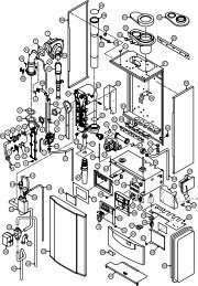
Fig. 1.1: Items supplied with unit (<strong>turboMAX</strong> <strong>plus</strong>)<br />
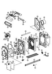
Fig. 1.2: Items supplied with unit (thermoCOMP<strong>AC</strong>T)<br />
Item Quantity Description<br />
Item Quantity Description<br />
1 1 Boiler<br />
2 1 Flue restriction ring<br />
3 1 Controls cover door<br />
4 1 Lower cover plate (packed in bottom<br />
packaging)<br />
5 1 Cold water inlet valve<br />
6 3 Flow <strong>and</strong> return service value, gas service<br />
valve<br />
7 5 Copper tails <strong>for</strong> gas <strong>and</strong> water pipework<br />
8 1 Template<br />
9 2 Guarantee Card <strong>and</strong> Benchmark log book<br />
10 1 <strong>Installation</strong> <strong>and</strong> connection accessories <strong>and</strong><br />
PRV packages incl. DHW outlet union nut<br />
11 3 <strong>Installation</strong> <strong>and</strong> <strong>Servicing</strong>, Users <strong>and</strong> Flue<br />
<strong>Installation</strong> <strong>Instructions</strong><br />
12 1 Hanging bracket<br />
1 1 Boiler<br />
2 1 Flue restriction ring<br />
3 1 Controls cover door<br />
4 1 Lower cover plate (packed in bottom<br />
packaging)<br />
5 3 Flow <strong>and</strong> return service value, gas service<br />
valve<br />
6 3 Copper tails <strong>for</strong> gas <strong>and</strong> water pipework<br />
7 1 Template<br />
8 2 Guarantee Card <strong>and</strong> Benchmark log book<br />
9 1 <strong>Installation</strong> <strong>and</strong> connection accessories <strong>and</strong><br />
PRV packages<br />
10 3 <strong>Installation</strong> <strong>and</strong> <strong>Servicing</strong>, Users <strong>and</strong> Flue<br />
<strong>Installation</strong> <strong>Instructions</strong><br />
11 1 Hanging bracket<br />
4<br />
<strong>Instructions</strong> <strong>for</strong> <strong>Installation</strong> <strong>and</strong> <strong>Servicing</strong> <strong>turboMAX</strong> <strong>plus</strong> <strong>and</strong> thermoCOMP<strong>AC</strong>T R1
Introduction 2<br />
2 Introduction<br />
2.1 General In<strong>for</strong>mation<br />
Note!<br />
This boiler must be installed <strong>and</strong> serviced by a<br />
competent person in accordance with the Gas<br />
Safety (<strong>Installation</strong> <strong>and</strong> Use) Regulations 1998.<br />
In the UK "CORGI“ registered installers<br />
undertake the work to a safe <strong>and</strong> satisfactory<br />
st<strong>and</strong>ard.<br />
<strong>turboMAX</strong> <strong>plus</strong> boiler<br />
The <strong>turboMAX</strong> <strong>plus</strong> is a fully automatic, wall mounted,<br />
room sealed combination boiler <strong>for</strong> central heating <strong>and</strong><br />
domestic hot water. Domestic hot water is supplied<br />
directly from the boiler, without requiring a copper<br />
cylinder, cold water tank, feed <strong>and</strong> expansion tank <strong>and</strong><br />
associated pipework. Domestic hot water has priority<br />
over central heating.<br />
The <strong>turboMAX</strong> <strong>plus</strong> range consists of models with<br />
outputs <strong>for</strong> domestic hot water of 24 kW , 28 kW <strong>and</strong> 37<br />
kW. All <strong>turboMAX</strong> <strong>plus</strong> boilers are available in Natural<br />
Gas. The 24 <strong>and</strong> 28 kW versions are also available in<br />
LPG.<br />
<strong>turboMAX</strong> <strong>plus</strong> combination boilers incorporate a<br />
warmstart facility that keeps the domestic hot water<br />
heat exchanger hot, providing an instantaneous delivery<br />
of domestic hot water.<br />
The temperature in the domestic hot water heat<br />
exchanger is limited by the boiler control system <strong>and</strong> it<br />
is not necessary to install a scale reducer on the cold<br />
mains to the boiler.<br />
However, in exceptionally hard water areas to prevent<br />
scale <strong>for</strong>mation in the property hot water system<br />
pipework, a scale reducer may be fitted.<br />
The heating system can be filled using the built-in filling<br />
loop contained within the boiler.<br />
thermoCOMP<strong>AC</strong>T boiler<br />
The thermoCOMP<strong>AC</strong>T is a fully automatic, wall mounted,<br />
room sealed system boiler <strong>for</strong> central heating <strong>and</strong><br />
domestic hot water (where a separate indirect hot water<br />
storage cylinder is also incorporated in the system).<br />
The thermoCOMP<strong>AC</strong>T range consists of models with<br />
outputs of 15, 20, 24, 28 kW <strong>and</strong> 37 kW.<br />
All thermoCOMP<strong>AC</strong>T boilers are available in Natural Gas.<br />
The 20 <strong>and</strong> 28 kW versions are also available in LPG.<br />
systems are available, the st<strong>and</strong>ard concentric flue<br />
system (100 mm outside diameter) <strong>and</strong> a larger<br />
diameter concentric flue system (125 mm outside<br />
diameter) which allows longer flue lengths to be<br />
achieved. Flue extensions <strong>and</strong> additional bends <strong>and</strong><br />
elbows are available <strong>for</strong> both flue systems to increase<br />
the siting flexibility.<br />
There is also a 100 mm diameter concentric flue<br />
accessory which connects to the alternative rear flue<br />
outlet on the boiler <strong>for</strong> direct through the wall<br />
installations. The boilers are not suitable <strong>for</strong> external<br />
installation. If desired, an inhibitor may be used in the<br />
system. Guidance on the use of inhibitors is contained in<br />
these instructions.<br />
All boilers have a built in diagnostic system which<br />
indicates the operational status of the boiler.<br />
This feature provides key in<strong>for</strong>mation to aid<br />
commissioning <strong>and</strong> fault finding.<br />
The data badge is fitted on the rear of the control panel.<br />
See text of General Requirements <strong>for</strong> installation<br />
requirements or notes.<br />
Vaillant Ltd. support the Benchmark initiative.<br />
Within the in<strong>for</strong>mation pack, you will find a Benchmark<br />
Log Book. It is very important that this is completed<br />
correctly at the time of installation, commissioning <strong>and</strong><br />
h<strong>and</strong>over to the user.<br />
2.3 EC designation<br />
<strong>turboMAX</strong> <strong>plus</strong> (824/828/837) <strong>and</strong> thermoCOMP<strong>AC</strong>T<br />
boilers (615/620/624/628/637) carry the "CE" Mark. This<br />
demonstrates that the boilers fulfil the essential<br />
requirements of the Gas Appliance<br />
Directive(90/396/EEC) <strong>and</strong> the Gas Appliance (Safety)<br />
Regulations 1992.<br />
The "CE" Mark also demonstrates that the boilers<br />
comply with the requirements of the Electromagnetic<br />
Compatibility Directive (89/336/EEC), the Low Voltage<br />
Directive (72/23/EEC), the Boiler Efficiency Directive<br />
(92/42/EEC) <strong>and</strong> the Boiler (Efficiency) Regulations<br />
1993.<br />
2.2 General Notes<br />
The boilers have been designed <strong>for</strong> use with a sealed<br />
central heating system, <strong>and</strong> come fully tested <strong>and</strong><br />
assembled with a built in circulating pump, expansion<br />
vessel <strong>and</strong> diverter valve (<strong>turboMAX</strong> <strong>plus</strong> only). The<br />
boilers are not suitable <strong>for</strong> use on open vented systems.<br />
The boilers are easily sited on any internal wall <strong>and</strong> can<br />
be installed with either a horizontal or vertical RSF<br />
(room sealed fan assisted) flue. Two types of flue<br />
<strong>Instructions</strong> <strong>for</strong> <strong>Installation</strong> <strong>and</strong> <strong>Servicing</strong> <strong>turboMAX</strong> <strong>plus</strong> <strong>and</strong> thermoCOMP<strong>AC</strong>T R1 5
3 Boiler Specification<br />
3 Boiler Specification<br />
3.1 Technical Data<br />
<strong>turboMAX</strong> <strong>plus</strong> <strong>turboMAX</strong> <strong>plus</strong> <strong>turboMAX</strong> <strong>plus</strong><br />
824/2 E 828/2 E 837 E Units<br />
(VUW GB 242/2-5) (VUW GB 282/2-5) (VUW GB 362/2-5)<br />
Maximum CH heat input (net) 26.7 (91,200) 31.1 (106,200) 31.1 (106,200) kW (Btu/h)<br />
CH heat output range (80/60 °C) 8.9 - 24 10.4 - 28 10.9 - 28* (36,.9)<br />
(30,400 - 81,900) (35,500 - 95,500) (37,200 - 95,500) kW (Btu/h)<br />
Maximum DHW heat input (net) 26.7 (91,200) 31.1 (106,200) 40.5 (138,300) kW (Btu/h)<br />
SEDBUK B<strong>and</strong> D D D<br />
SAP Seasonal Efficiency 79.6 79.7 79.8 %<br />
DHW heat output 24 28 36.9 kW<br />
DHW flow rate ∆T = 35 °C rise 9.8 11.5 15.1 l/min<br />
DHW flow rate at factory set<br />
temperature rise (∆T 42 °C) 8.2 9.5 12.6 l/min<br />
Mains water pressure required<br />
<strong>for</strong> max. flow rate 0.5 0.5 0.5 bar<br />
Minimum water flow rate 1.5 1.5 1.5 l/min<br />
Mains water pressure required<br />
<strong>for</strong> min. flow rate 0.15 0.15 0.15 bar<br />
Maximum inlet water pressure 10 10 10 bar<br />
Inlet gas working pressure<br />
required (natural gas) 20 20 20 mbar<br />
Gas supply (G20) Gross CV (s.t.) 37.8 37.8 37.8 MJ/m 3<br />
Gas burner pressure max. rate 9.8 10.5 12.0 mbar<br />
Gas burner pressure ignition rate 1.9 1.8 1.2 mbar<br />
Gas rate max. (DHW) 2.8 3.3 4.3 m 3 /h<br />
CH temperature flow range 35 - 82 35 - 82 35 - 82 °C<br />
Minimum CH water flow<br />
(<strong>for</strong> 20 °C rise) 1032 1203 1203 ** l/h<br />
Pump pressure available 0.25 (25) 0.25 (25) 0.25 (25) bar (KPa)<br />
Expansion vessel<br />
pre-charge pressure 0.75 0.75 0.75 bar<br />
Maximum CH system pressure 3 3 3 bar<br />
Weight 43 45 48 kg<br />
Primary water content 2.0 2.0 2.2 l<br />
Electrical supply 230/50 230/50 230/50 V~/Hz<br />
External fuse 3 3 3 A<br />
Power input 150 150 130 W<br />
Case height 800 800 800 mm<br />
Case width 440 440 440 mm<br />
Case depth 338 338 338 mm<br />
* factory setting; ** at factory setting<br />
6<br />
<strong>Instructions</strong> <strong>for</strong> <strong>Installation</strong> <strong>and</strong> <strong>Servicing</strong> <strong>turboMAX</strong> <strong>plus</strong> <strong>and</strong> thermoCOMP<strong>AC</strong>T R1
Boiler Specification 3<br />
thermoCOMP<strong>AC</strong>T thermoCOMP<strong>AC</strong>T thermoCOMP<strong>AC</strong>T thermoCOMP<strong>AC</strong>T thermoCOMP<strong>AC</strong>T<br />
615/2 E 620/2 E 624/2 E 628/2 E 637 E Units<br />
(VU GB 152/2-5) (VU GB 202/2-5) (VU GB 242/2-5) (VU GB 282/2-5) (VU GB 362-5)<br />
Maximum CH heat input 16.5 22.0 26.7 31.1 40.5 kW<br />
(net) (56,100) (74,800) (91,200) (106,200) (138,300) (Btu/h)<br />
CH heat output range 6.5. - 15 7.7 - 20 8.9 - 24 10.4 - 28 10.5 - 36.9 kW<br />
(80/60 °C) (22,300-51,200) (26,300 - 68,300) (30,400 - 81,900) (35,500 - 95,500) (35,800 - 126,000) (Btu/h)<br />
SEDBUK B<strong>and</strong> D D D D D<br />
SAP Seasonal Efficiency 79.0 79.7 79.7 79.8 79.8 %<br />
Inlet gas working pressure<br />
required (natural gas) 20 20 20 20 20 mbar<br />
Gas supply (G20) 37.8 37.8 37.8 37.8 37.8 MJ/m 3<br />
Gross CV (s.t.)<br />
Gas burner pressure 9.9 9.0 9.8 10.5 12.0 mbar<br />
max. rate<br />
Gas burner pressure 2.2 1.5 1.9 1.8 1.2 mbar<br />
ignition rate<br />
CH temperature 35 - 82 35 - 82 35 - 82 35 - 82 35 - 82 °C<br />
flow range<br />
Minimum CH water flow<br />
(<strong>for</strong> 20 °C rise) 650 860 1032 1203 1587 l/h<br />
Pump pressure available 0.25 (25) 0.25 (25) 0.25 (25) 0.25 (25) 0.17 (17) bar<br />
(KPa)<br />
Expansion vessel<br />
pre-charge pressure 0.75 0.75 0.75 0.75 0.75 bar<br />
Maximum CH 3 3 3 3 3 bar<br />
system pressure<br />
Weight 38 39 41 43 45 kg<br />
Primary water content 2.0 2.0 2.0 2.0 2.2 l<br />
Electrical supply 230/50 230/50 230/50 230/50 230/50 V~/Hz<br />
External fuse 3 3 3 3 3 A<br />
Power input 150 150 150 150 130 W<br />
Case height 800 800 800 800 800 mm<br />
Case width 440 440 440 440 440 mm<br />
Case depth 338 338 338 338 338 mm<br />
<strong>Instructions</strong> <strong>for</strong> <strong>Installation</strong> <strong>and</strong> <strong>Servicing</strong> <strong>turboMAX</strong> <strong>plus</strong> <strong>and</strong> thermoCOMP<strong>AC</strong>T R1 7
C<br />
C<br />
3 Boiler Specification<br />
3.2 Boiler connections (<strong>turboMAX</strong> <strong>plus</strong>)<br />
264<br />
102<br />
6<br />
8<br />
145<br />
Key:<br />
1 Heating system return (22 mm tail)<br />
2 Gas connection (15 mm tail)<br />
3 Heating system flow (22 mm tail, 22 mm <strong>for</strong> 637)<br />
4 Flue outlet (100 mm flue with turret)<br />
5 Hanging bracket<br />
6 Rear flue outlet<br />
3.4 Functional Diagram (<strong>turboMAX</strong> <strong>plus</strong>)<br />
902<br />
638<br />
7<br />
6<br />
1<br />
2<br />
31<br />
30<br />
5 4 3 2 1<br />
3<br />
29<br />
35 35<br />
100<br />
100<br />
130 180<br />
4<br />
5<br />
6<br />
u<br />
28<br />
Fig. 3.1: Connection diameters <strong>turboMAX</strong> <strong>plus</strong><br />
Key:<br />
1 Heating system return (22 mm tail)<br />
2 Cold water connection with shut off valve<br />
(15 mm tail)<br />
3 Gas connection (15 mm tail, 22mm <strong>for</strong> 837)<br />
4 Hot water connection (15 mm tail)<br />
5 Heating system flow (22 mm tail)<br />
6 Flue outlet (100 mm flue with turret)<br />
7 Hanging bracket<br />
8 Rear flue outlet<br />
3.3 Boiler connections (thermoCOMP<strong>AC</strong>T)<br />
5<br />
4 3 2<br />
1<br />
7<br />
8<br />
9<br />
10<br />
11<br />
12<br />
13<br />
14<br />
15<br />
i<br />
27<br />
26<br />
25<br />
24<br />
23<br />
22<br />
21<br />
20<br />
19<br />
18<br />
17<br />
16<br />
902<br />
638<br />
264<br />
102<br />
6<br />
8<br />
145<br />
7<br />
6<br />
5 4 3 2 1<br />
130 80 180<br />
55 55<br />
100 100<br />
5 4 3 2 1<br />
Fig. 3.2: Connection diameters thermoCOMP<strong>AC</strong>T<br />
Fig. 3.3: Functional Diagram <strong>turboMAX</strong> <strong>plus</strong><br />
Key:<br />
1 Air duct<br />
2 Fan<br />
3 Main heat exchanger<br />
4 Temperature sensor (NTC I)<br />
5 Flame sensing electrodes<br />
6 Modulating burner<br />
7 Fully modulating automatic gas value<br />
8 Maximum hot water temperature control<br />
9 Maximum radiator temperature control<br />
10 Diverter valve<br />
11 DHW heat exchanger<br />
12 Automatic bypass valve<br />
13 CH flow service valve<br />
14 Hot water outlet<br />
15 Gas service valve<br />
16 Cold water service valve<br />
17 CH return service valve<br />
18 Pressure relief valve<br />
19 Aqua sensor (DHW flow switch)<br />
20 Temperature sensor (NTC III)<br />
21 Main on/off control<br />
8<br />
<strong>Instructions</strong> <strong>for</strong> <strong>Installation</strong> <strong>and</strong> <strong>Servicing</strong> <strong>turboMAX</strong> <strong>plus</strong> <strong>and</strong> thermoCOMP<strong>AC</strong>T R1
Boiler Specification 3<br />
22 Pressure gauge<br />
23 Display<br />
24 Expansion vessel<br />
25 Expansion vessel charging valve<br />
26 Circulating pump<br />
27 Automatic air vent<br />
28 Ignition electrode<br />
29 Temperature sensor (NTC II)<br />
30 Air pressure switch<br />
31 Flue gas duct<br />
19 Expansion vessel charging valve<br />
20 Circulating pump<br />
21 Automatic air vent<br />
22 Ignition electrode<br />
23 Temperature sensor (NTC II)<br />
24 Air pressure switch<br />
25 Flue gas duct<br />
3.5 Functional Diagram (thermoCOMP<strong>AC</strong>T)<br />
1<br />
2<br />
25<br />
24<br />
3<br />
23<br />
4<br />
5<br />
6<br />
22<br />
21<br />
7<br />
8<br />
9<br />
20<br />
19<br />
18<br />
17<br />
16<br />
15<br />
10<br />
14<br />
11<br />
13<br />
12<br />
Fig. 3.4: Functional Diagram thermoCOMP<strong>AC</strong>T<br />
Key:<br />
1 Air duct<br />
2 Fan<br />
3 Main heat exchanger<br />
4 Temperature sensor (NTC I)<br />
5 Flame sensing electrodes<br />
6 Modulating burner<br />
7 Fully modulating automatic gas value<br />
8 This control has no function on this boiler<br />
9 Maximum radiator temperature control<br />
10 Automatic bypass valve<br />
11 CH flow service valve<br />
12 Gas service valve<br />
13 CH return service valve<br />
14 Pressure relief valve<br />
15 Main on/off control<br />
16 Pressure gauge<br />
17 Display<br />
18 Expansion vessel<br />
<strong>Instructions</strong> <strong>for</strong> <strong>Installation</strong> <strong>and</strong> <strong>Servicing</strong> <strong>turboMAX</strong> <strong>plus</strong> <strong>and</strong> thermoCOMP<strong>AC</strong>T R1 9
4 General Requirements<br />
4 General Requirements<br />
4.1 Related Documents<br />
The installation of the boiler must be in accordance with<br />
the relevant requirements of Gas Safety (<strong>Installation</strong> <strong>and</strong><br />
Use) Regulations 1998, Health <strong>and</strong> Safety Document No.<br />
635 (The Electricity at Work Regulations 1989), BS7671<br />
(IEE Wiring Regulations) <strong>and</strong> the Water Supply (Water<br />
Fittings) Regulations 1999, or the Water Bylaws 2000<br />
(Scotl<strong>and</strong>). It should also be in accordance with the<br />
relevant requirements of the Local Authority, Building<br />
Regulations, Building Regulations (Scotl<strong>and</strong>), Building<br />
Regulations (Northern Irel<strong>and</strong>) <strong>and</strong> the relevant<br />
recommendations of the following British St<strong>and</strong>ard;<br />
Including current amendments to Approved Documents<br />
Part L <strong>and</strong> J.:<br />
BS 5440: Flues <strong>and</strong> ventilation of gas fired boilers not<br />
exceeding 70 kW net:<br />
- Part 1: Flues<br />
- Part 2: Ventilation<br />
BS 5449: Specification <strong>for</strong> <strong>for</strong>ced circulation hot water<br />
<strong>for</strong> domestic premises.<br />
BS 5546: Specification <strong>for</strong> gas hot water supplies <strong>for</strong><br />
domestic premises.<br />
BS 6700: Services supplying water <strong>for</strong> domestic use<br />
within buildings <strong>and</strong> their curtilages.<br />
BS 6798: Specification <strong>for</strong> installation of gas fired<br />
boilers not exceeding 70 kW input net.<br />
BS 6891: Specification <strong>for</strong> installation of low pressure<br />
gas pipework up to 28 mm (R1) in domestic premises<br />
(2 nd family gas).<br />
BS 7593: Treatment of water in domestic hot water<br />
central heating systems.Institute of Gas Engineers<br />
Publication IGE/UP/7/1998: Guide <strong>for</strong> <strong>Installation</strong> in<br />
Timber Framed Housing. Benchmark Code of Practice.<br />
Building Regulations Approved Documents Part L 2002<br />
Part J 2002.<br />
Important!<br />
The appliance must be installed <strong>and</strong> serviced by<br />
a competent person as stated in the Gas Safety<br />
(<strong>Installation</strong> <strong>and</strong> Use) Regulations 1998. In IE,<br />
the installation must be in accordance with the<br />
current edition of IS 813 'Domestic Gas<br />
<strong>Installation</strong>s', the current Building Regulations<br />
<strong>and</strong> reference should be made to the current<br />
ETCI rules <strong>for</strong> electrical installation.<br />
Preliminary remarks<br />
This appliance should only be installed in conjunction<br />
with a Vaillant flue system.<br />
Install the flue system as detailed in the separate flue<br />
installation instructions supplied with this boiler.<br />
4.2 Boiler location<br />
The location chosen <strong>for</strong> the boiler must permit the<br />
provision of a satisfactory flue termination. The location<br />
must also provide adequate space <strong>for</strong> servicing <strong>and</strong> air<br />
circulation around the boiler. The boiler may be installed<br />
in any room, although particular attention is drawn to<br />
the requirements of BS7671 (IEE Regulations), the<br />
electrical provisions of the Building Regulations<br />
(Scotl<strong>and</strong>) <strong>and</strong> in IE the current edition of IS 813 <strong>and</strong> the<br />
current ETCI rules, in respect of the installation of a<br />
boiler in a room containing a bath or shower.<br />
Note!<br />
Where a room sealed boiler is installed in a room<br />
containing a bath or shower, any electrical<br />
switch or boiler control utilising mains<br />
electricity should be so situated that it cannot<br />
be touched by a person using the bath or<br />
shower.<br />
Where the installation of the boiler will be in an unusual<br />
location, special procedures may be necessary <strong>and</strong> BS<br />
5546 <strong>and</strong> BS 6798 give detailed guidance on this<br />
aspect. The boiler must be mounted on a flat, vertical<br />
wall, which must be sufficiently robust to take the<br />
weight of the boiler. The boiler may be installed on a<br />
combustible wall, subject to the requirements of the<br />
Local Authorities <strong>and</strong> Building Regulations.<br />
A compartment used to enclose the boiler must be<br />
designed <strong>and</strong> constructed specifically <strong>for</strong> this purpose.<br />
(An existing cupboard or compartment may be used<br />
provided that it is modified <strong>for</strong> the purpose). Details of<br />
essential features of cupboard/compartment design<br />
including airing cupboard installations are given in BS<br />
6891. In IE the current edition of IS 813.<br />
If the boiler is to be fitted in a timber framed building, it<br />
should be fitted in accordance with Institute of Gas<br />
Engineers Publication IGE/UP/7/1998 "Guide <strong>for</strong> Gas<br />
<strong>Installation</strong> in Timber Framed Housing“.<br />
4.3 Gas Supply<br />
The gas supplier should ensure the availability of an<br />
adequate supply of gas.<br />
A gas meter may only be connected to the service pipe<br />
by the supplier of gas or their contractor.<br />
An existing meter should be checked to ensure that it is<br />
capable of passing the rate of gas supply required.<br />
<strong>Installation</strong> pipes should be fitted in accordance with BS<br />
6891. Pipework from the meter to the boiler must be of<br />
an adequate size. Do not use pipes of a smaller size than<br />
the boiler gas connection (15 mm, 22 mm <strong>for</strong> 837/637).<br />
The complete installation must be tested <strong>for</strong> soundness<br />
<strong>and</strong> purged as described in BS 6891.<br />
10<br />
<strong>Instructions</strong> <strong>for</strong> <strong>Installation</strong> <strong>and</strong> <strong>Servicing</strong> <strong>turboMAX</strong> <strong>plus</strong> <strong>and</strong> thermoCOMP<strong>AC</strong>T R1
70<br />
15<br />
48<br />
4<br />
603<br />
General Requirements 4<br />
4.4 Flue system<br />
Note!<br />
The boilers are delivered ready <strong>for</strong> installation<br />
utilising a top outlet flue assembly. For<br />
installation with a rear outlet flue assembly<br />
refer to the boiler flue outlet adaptation in the<br />
flue instructions.<br />
4.4.1 Top outlet flue system<br />
(100 mm outside diameter)<br />
The top outlet horizontal flue system (Art. No. 303 807)<br />
is suitable <strong>for</strong> installations up to 720 mm measured<br />
from the centre of the boiler flue outlet to the outside<br />
face of the wall. Flue extensions are available to extend<br />
this length up to 5.3 m <strong>for</strong> 15/20 kW; 4.5 m <strong>for</strong> 24 kW<br />
<strong>and</strong> 3.2 m <strong>for</strong> 28/37 kW.<br />
Both 90° bends <strong>and</strong> 45° elbows are also available to<br />
increase siting flexibility.<br />
A vertical flue system is also available (Art. No. 303<br />
800).<br />
Refer to flue system installation instructions <strong>for</strong> full<br />
details.<br />
750<br />
48<br />
4.4.2 Rear outlet flue system<br />
(100 mm outside diameter)<br />
The rear outlet horizontal flue system (Art. No. 303 817)<br />
is suitable <strong>for</strong> installations up to 600 mm wall thickness.<br />
Fig. 4.3: Art.-No. 303 817<br />
750<br />
4.4.3 Extended top outlet flue system<br />
(125 mm outside diameter)<br />
A top outlet horizontal flue system of 125 mm outside<br />
diameter is also available (Art. No. 303 609) <strong>and</strong> can be<br />
used to achieve flue lengths of up to 12.9 m <strong>for</strong> 15/20/24<br />
kW; 10 m <strong>for</strong> 28/37 kW.<br />
Both 45° <strong>and</strong> 90° bends <strong>and</strong> elbows are also available to<br />
increase siting flexibility.<br />
A vertical 125 mm concentric flue system is also<br />
available (Art. No. 303 600).<br />
Refer to flue system installation instructions <strong>for</strong> full<br />
details.<br />
Fig. 4.1: Art.-No. 303 807<br />
A vertical flue system is also available (Art. No. 303<br />
800).<br />
Refer to flue system installation instructions <strong>for</strong> full<br />
details.<br />
1103<br />
70<br />
48 1285<br />
Fig. 4.4: Art.-No. 303 609<br />
Fig. 4.2: Art.-No. 303 800<br />
<strong>Instructions</strong> <strong>for</strong> <strong>Installation</strong> <strong>and</strong> <strong>Servicing</strong> <strong>turboMAX</strong> <strong>plus</strong> <strong>and</strong> thermoCOMP<strong>AC</strong>T R1 11
4 General Requirements<br />
4.4.4 Flue termination<br />
The following details refer to both flue systems.<br />
a. The terminal must be positioned such that the products<br />
of combustion can disperse freely at all times.<br />
b. In certain weather conditions a plume of water<br />
vapour may be visible from the flue terminal.<br />
Positions where this could be a nuisance should be<br />
avoided.<br />
c. If the terminal is fitted less than 2 m above a<br />
balcony, above ground or above a flat roof to which<br />
people have access then a suitable terminal guard;<br />
must be provided <strong>and</strong> fitted (Model K3 - made by<br />
Tower Flue Components, Tonbridge, TN9 1TB).<br />
Note!<br />
Vertical flues must not terminate within<br />
600 mm of an openable window, air vent or any<br />
other ventilation opening.<br />
The flue assembly shall be so placed or shielded as to<br />
prevent ignition or damage to any part of the building.<br />
A 1)<br />
Terminal position <strong>for</strong> fan-assisted flue<br />
(minimum distance)<br />
Directly below an openable, above an opening<br />
or horizontal to an opening i.e. air brick, opening<br />
mm<br />
window or other, etc 300<br />
B Below gutters, soil pipes or drain pipes 25<br />
C Below eaves 25<br />
D Below balconies (below car port roof) 25<br />
E From vertical drain pipes <strong>and</strong> soil pipes 25<br />
F From internal or external corners 25<br />
G Above ground or balcony level 300<br />
H From a surface or boundary facing a terminal 600*<br />
H From a terminal facing a terminal 1200<br />
J<br />
From an opening in a car port (e.g. door, window)<br />
into a dweling 1200<br />
K Vertically from a terminal on the same wall 1500<br />
L Horizontally from a terminal on the same wall 300<br />
M Distance from adjacent wall <strong>for</strong> vertical Flue 500<br />
H, I<br />
A<br />
G<br />
F J<br />
E<br />
Fig. 4.5: Flue termination<br />
A<br />
A<br />
G<br />
A<br />
BCD<br />
F<br />
F<br />
B F<br />
M<br />
G<br />
L<br />
K<br />
L K<br />
1) In addition, the terminal should not be nearer than 150mm to an<br />
opening in the building fabric <strong>for</strong>med <strong>for</strong> the purpose of<br />
accommodating a built-in element such as a window.<br />
* BS 5440-1 It is recommended that a fanned flue terminal should<br />
be positioned as follows: a) at least 2m from an opening in a<br />
building directly opposite, <strong>and</strong> b) so that the products of<br />
combustion are not directed to discharge across a boundary.<br />
4.5 Air supply<br />
Detailed recommendations <strong>for</strong> air supply are given in BS<br />
5440: Part 2.<br />
It is not necessary to have an air vent in the room or<br />
internal space in which the boiler is installed.<br />
4.6 Cupboard or compartment ventilation<br />
The boilers are very high efficiency appliances. As a<br />
consequence the heat loss from the appliance casing<br />
during operation is very low. For cupboard or<br />
compartment installations it is there<strong>for</strong>e not necessary<br />
to provide any high or low level permanent air vents <strong>for</strong><br />
cooling purposes.<br />
4.7 Electrical supply<br />
A 230 V, ~ 50 Hz single phase electricity supply fused to<br />
3 Amp. must be provided in accordance with the latest<br />
edition of BS7671 (IEE Wiring Regulations) <strong>and</strong> any other<br />
local regulations that may apply. In IE, reference should<br />
be made to the current edition of the ETCI rules.<br />
The method of connection to the mains electricity<br />
supply must provide a means of completely isolating the<br />
boiler <strong>and</strong> its ancillary controls. Isolation is preferably by<br />
the use of a fused three pin plug <strong>and</strong> unswitched<br />
shuttered socket outlet, both complying with the<br />
12<br />
<strong>Instructions</strong> <strong>for</strong> <strong>Installation</strong> <strong>and</strong> <strong>Servicing</strong> <strong>turboMAX</strong> <strong>plus</strong> <strong>and</strong> thermoCOMP<strong>AC</strong>T R1
General Requirements 4<br />
requirements of BS 1363. Alternatively, a 3 Amp. fused<br />
doublepole switch with a 3 mm contact separation on<br />
both poles may be used.<br />
Important!<br />
This appliance must be earthed.<br />
4.8 Guide to system requirements<br />
4.8.1 Water circulation system<br />
Detailed recommendations <strong>for</strong> the water circulation<br />
system are given in BS 6798 <strong>and</strong> BS 5449: Part 1 (<strong>for</strong><br />
small bore <strong>and</strong> micro bore central heating systems).<br />
Pipework not <strong>for</strong>ming part of the useful heating surface<br />
should be insulated to help prevent heat loss <strong>and</strong><br />
possible freezing, particularly where pipes are run<br />
through roof spaces <strong>and</strong> ventilated underfloor spaces.<br />
Draining taps must be located in accessible positions<br />
which permit the draining of the whole system including<br />
the boiler <strong>and</strong> the hot water system. Draining taps<br />
should be at least 1/2 in. BSP nominal size <strong>and</strong> be in<br />
accordance with BS 2879.<br />
The boiler is suitable <strong>for</strong> use with minibore or microbore<br />
systems. Copper tubing to BS 2871: Part 1 should be<br />
used <strong>for</strong> water carrying pipework. All capillary joints in<br />
all DHW pipework must be made with lead free solder.<br />
Particularly where a new boiler is to be fitted to an<br />
existing system, it is good practice that the system is<br />
thoroughly cleansed. This cleansing should take place<br />
prior to the fitting of the new boiler <strong>and</strong> be in<br />
accordance with BS 7593.<br />
For advice on the application of system cleansers<br />
contact either Sentinel, GE Betz. Widnes, Cheshire,<br />
WA8 8UD.<br />
Tel: 0151 420 9595<br />
or:<br />
Fernox<br />
Alpha-Fry Technologies<br />
T<strong>and</strong>em House<br />
Marlow Way, Beddington Farm Road<br />
Croydon CRO 4xS<br />
Tel. 0870 601 5000<br />
Fernox technical<br />
help line 01799 550811<br />
(Alternative methods of filling sealed systems are given<br />
in BS 5449).<br />
4.8.3 Pressure relief valve<br />
A pressure relief valve is provided with the boiler. This<br />
safety device is required on all sealed C.H. systems <strong>and</strong><br />
is preset at 3 bar <strong>and</strong> provided with a 15 mm<br />
compression connection <strong>for</strong> a discharge pipe, which<br />
must be of no less than 15 mm in diameter. The Pressure<br />
Relief Valve must not be used <strong>for</strong> draining purposes.<br />
4.8.4 Pressure gauge<br />
This is factory fitted to the boiler <strong>and</strong> indicates the<br />
primary circuit pressure to facilitate filling <strong>and</strong> testing.<br />
4.8.5 Expansion vessel<br />
The 15 <strong>and</strong> 20 kW thermoCOMP<strong>AC</strong>T boilers as well as<br />
the 24 kW <strong>turboMAX</strong> <strong>plus</strong> boiler incorporate a 6 litre<br />
expansion vessel which is suitable <strong>for</strong> a sealed heating<br />
system with a maximum water content of 60 litres. A<br />
10 litre expansion vessel kit is available as an optional<br />
accessory <strong>for</strong> <strong>for</strong> the <strong>turboMAX</strong> <strong>plus</strong> 24 kW boiler <strong>and</strong><br />
the 15 <strong>and</strong> 20 kW thermoCOMP<strong>AC</strong>T boilers.<br />
The 28, 37 <strong>turboMAX</strong> <strong>plus</strong> <strong>and</strong> 24, 28, 37 kW<br />
thermoCOMP<strong>AC</strong>T boilers incorporate a 10 litre expansion<br />
vessel which is suitable <strong>for</strong> a sealed heating system with<br />
a maximum water content of 100 litres.<br />
If the nominal capacity of the built in expansion vessel is<br />
not sufficient <strong>for</strong> the heating system (<strong>for</strong> instance in<br />
case of modernization of old open systems) an<br />
additional expansion vessel can be installed external to<br />
the boiler. It should be fitted in the return pipe as close<br />
as possible to the boiler in accordance with BS 5449:<br />
Part 1.<br />
Guidance on the sizing of an additional expansion vessel<br />
is given in Table on page 14.<br />
4.8.2 Filling <strong>and</strong> make up<br />
The system can be filled using the built in filling loop<br />
(<strong>turboMAX</strong> <strong>plus</strong> only) or via a separate filling point fitted<br />
at a convinient position on the heating circuit<br />
(thermoCOMP<strong>AC</strong>T). The connection must be removed<br />
when filling is completed. Where local Water Authority<br />
regulation does not allow temporary connection, a<br />
sealed system filler pump with break tank must be used.<br />
The heating system will not be filled automatically from<br />
the domestic hot water side.<br />
<strong>Instructions</strong> <strong>for</strong> <strong>Installation</strong> <strong>and</strong> <strong>Servicing</strong> <strong>turboMAX</strong> <strong>plus</strong> <strong>and</strong> thermoCOMP<strong>AC</strong>T R1 13
4 General Requirements<br />
Vessel Volume [L]<br />
Initial system pressure (bar) 1.0 1.5<br />
Pressure relief valve setting (bar) 3.0<br />
Total water content of system ltres<br />
25 2.7 3.9<br />
50 5.4 7.8<br />
100 10.9 15.6<br />
125 13.6 19.5<br />
Lift [mbar]<br />
700<br />
650<br />
600<br />
550<br />
500<br />
450<br />
400<br />
350<br />
300<br />
250<br />
Pump switch in position III (pre-delivery setting)<br />
150 16.3 23.4<br />
175 19.1 27.3<br />
200 21.8 31.2<br />
225 24.5 35.1<br />
250 27.2 39.0<br />
275 30.0 42.9<br />
300 32.7 46.8<br />
325 35.7 50.7<br />
350 38.1 54.6<br />
375 40.9 58.5<br />
400 43.6 62.4<br />
425 46.3 66.3<br />
450 49.0 70.2<br />
475 51.8 74.1<br />
200<br />
150<br />
100<br />
50<br />
Pump switch in position II<br />
0 100 200 300 400 500 600 700 800 900 1000 1100 1200 1300 1400<br />
Fig. 4.6: Pump specifications 37 kW<br />
Volume flow [l/min]<br />
1500 1600 1700<br />
4.8.7 System by-pass<br />
An automatic system by-pass is included within the<br />
boiler. The boiler is suitable <strong>for</strong> use in systems with<br />
thermostatic radiator valves <strong>and</strong> no additional by-pass is<br />
required.<br />
4.8.8 Venting<br />
The boiler is fitted with an automatic air vent. Additional<br />
provision should be made to enable the heating system<br />
to be vented during filling <strong>and</strong> commissioning either by<br />
automatic air vents or manually.<br />
500 54.5 78.0<br />
For system volumes other than those given<br />
above, multiply the system volume by the<br />
factor across 0.109 0.156<br />
4.8.6 Circulating pump<br />
The circulating pump is included in the boiler. The pump<br />
head available <strong>for</strong> the heating system is shown in<br />
fig. 4.6.<br />
700<br />
Lift [mbar]<br />
650<br />
600<br />
550<br />
500<br />
450<br />
400<br />
350<br />
300<br />
250<br />
Pump switch in position III (Factory setting)<br />
200<br />
150<br />
100<br />
Pump switch in position II<br />
50<br />
0 100 200 300 400 500 600 700 800 900 1000 1100 1200 1300 1400<br />
Fig. 4.6: Pump specifications 12-28 kW<br />
Volume flow [l/hr]<br />
14<br />
<strong>Instructions</strong> <strong>for</strong> <strong>Installation</strong> <strong>and</strong> <strong>Servicing</strong> <strong>turboMAX</strong> <strong>plus</strong> <strong>and</strong> thermoCOMP<strong>AC</strong>T R1
Boiler <strong>Installation</strong> Sequence 5<br />
5 Boiler <strong>Installation</strong> Sequence<br />
5.1 General<br />
Preparation of boiler location<br />
Clearances required<br />
Mount the boiler on a flat <strong>and</strong> vertical area of wall of<br />
sufficient area <strong>for</strong> the boiler <strong>plus</strong> the required<br />
clearances <strong>for</strong> installation <strong>and</strong> servicing.<br />
The clearances are as detailed below <strong>and</strong> are shown on<br />
the installation template supplied with the boiler:<br />
- 150 mm below the boiler<br />
- 5 mm on either side of the boiler<br />
- 210 mm on top of the boiler<br />
- 500 mm in front of the boiler*<br />
* Clearance is only required to enable easier access to<br />
the boiler <strong>for</strong> servicing <strong>and</strong> may be provided by an<br />
openable door, etc.<br />
Selecting position of boiler<br />
Refer to "Boiler location“ <strong>for</strong> in<strong>for</strong>mation regarding<br />
siting the appliance. In general the boiler must be<br />
positioned such that.<br />
• There is adequate space around the boiler <strong>for</strong> service<br />
<strong>and</strong> maintenance.<br />
• The boiler can be correctly flued, i.e. the flue terminal<br />
position is sited in accordance with the flue<br />
termination section <strong>and</strong> the air/flue duct can be<br />
installed in accordance with the flue installation<br />
instructions supplied.<br />
• All necessary pipework can be connected, including<br />
the pressure relief valve.<br />
Note!<br />
Should it be necessary to run system pipework<br />
to above the boiler within the width of the<br />
casing, use the optional top connection<br />
accessory (Art.No. 306 251).<br />
Note!<br />
If the boiler is to be fitted in a timber framed<br />
building, it should be fitted in accordance with<br />
Institute of Gas Engineers Publication<br />
IGE/UP/7/1998 "Guide <strong>for</strong> Gas <strong>Installation</strong>s in<br />
Timber Framed Dwellings“.<br />
; y<br />
; y<br />
; y<br />
; y<br />
; y<br />
440<br />
Fig. 5.1: Dimensions of boiler<br />
;; yy<br />
;;;;;;<br />
yyyyyy<br />
;y;y<br />
800<br />
;;; yyy<br />
338<br />
Fig. 5.2: Free space required <strong>for</strong> installation<br />
<strong>Instructions</strong> <strong>for</strong> <strong>Installation</strong> <strong>and</strong> <strong>Servicing</strong> <strong>turboMAX</strong> <strong>plus</strong> <strong>and</strong> thermoCOMP<strong>AC</strong>T R1 15
5 Boiler <strong>Installation</strong> Sequence<br />
5.2 Using boiler template<br />
Fix the paper template to the wall ensuring that the<br />
correct flue exit point has been identified, ensure that<br />
the template is vertical.<br />
The template shows<br />
- The position of the fixing holes <strong>for</strong> the boiler<br />
mounting bracket (1).<br />
- The position of the connections.<br />
- The position of the flue exit hole.<br />
- Upper hole (2) indicates top outlet flue with flue<br />
turret facing rearward.<br />
- Lower hole (3) indicates rear outlet flue exiting<br />
directly through wall.<br />
• Mark the position of the hanging bracket fixing holes<br />
(1).<br />
• Drill 2 holes Ø 8 mm <strong>for</strong> the hanging bracket.<br />
Note!<br />
Use alternative fixing holes where necessary.<br />
Identify correct flue exit<br />
Mark the centre of the selected air/flue duct <strong>and</strong> its<br />
circumference, e.g. by drilling through the template. For<br />
installation of a rear exit outlet please refer to the<br />
installation instructions of the rear exit outlet kit<br />
(Art. No. 303 817).<br />
Other flue options<br />
Flue instructions <strong>for</strong> other flue systems such as vertical<br />
RSF flues, flues run to the side of the boiler <strong>and</strong> the use<br />
of additional bends etc. are detailed in the flue<br />
installation instructions provided with the boiler.<br />
Remove the template from the wall <strong>and</strong> plug the drilled<br />
holes using the wallplugs supplied.<br />
5.3 Fitting the boiler hanging bracket<br />
Fix the hanging bracket (1) to the wall using the screws<br />
supplied (2). (it may be necessary to use additional or<br />
alternative fixings to ensure adequate support).<br />
2102<br />
210<br />
60/100<br />
402<br />
171 174,5<br />
2<br />
5<br />
3<br />
5<br />
12,5<br />
1<br />
1<br />
1<br />
3<br />
Fig. 5.4: Free space required <strong>for</strong> installation<br />
Note!<br />
If the boiler is to be fitted in a timber framed<br />
building ensure that the bracket is secured to a<br />
substantial part of the timber frame capable of<br />
taking the weight of the boiler.<br />
<strong>turboMAX</strong> only<br />
07/2002<br />
200/202/240/242/280/282/824/828 Pro/Plus<br />
124163 21<br />
Fig. 5.3: Using Boiler template<br />
16<br />
<strong>Instructions</strong> <strong>for</strong> <strong>Installation</strong> <strong>and</strong> <strong>Servicing</strong> <strong>turboMAX</strong> <strong>plus</strong> <strong>and</strong> thermoCOMP<strong>AC</strong>T R1
VRC-VC<br />
I<br />
0<br />
Boiler <strong>Installation</strong> Sequence 5<br />
5.4 Install the flue system<br />
Fit the flue restrictor to the boiler (if required) <strong>and</strong><br />
install the flue system (refer to separate air/flue duct<br />
installation instructions <strong>for</strong> further in<strong>for</strong>mation).<br />
5.5 Fitting the boiler<br />
• Lift the boiler (3) up to the wall so that it is slightly<br />
above the hanging bracket (1).<br />
Note!<br />
Lift the boiler from either side at the bottom<br />
edge.<br />
5.7 Gas supply (<strong>turboMAX</strong> <strong>plus</strong>)<br />
• Connect the 15 mm compression gas service cock (1)<br />
<strong>and</strong> 15 mm copper outlet tail (22mm copper tail with<br />
837) (3) as supplied with the appliance (2) <strong>and</strong> tighten.<br />
• Connect a gas supply pipe of not less than 15 mm<br />
diameter to the copper tail (minimum 22 mm gas<br />
supply pipe with 837).<br />
• Tighten all connections.<br />
(Ensure the gas supply pipework is adequately sized<br />
such that a 20 mbar gas pressure is available at the<br />
boiler inlet at full flow rate).<br />
• Lower the boiler slowly onto the hanging bracket so<br />
that the cross member at the rear of the boiler fully<br />
engages onto the hanging bracket.<br />
5.6 Removing boiler casing<br />
• Turn both securing fasteners (1) anti-clockwise by 90°<br />
to release control panel (2).<br />
• Pull the case (3) <strong>for</strong>ward at the bottom to disengage<br />
from the securing clips.<br />
• Lift the case slightly to clear the top locations <strong>and</strong> pull<br />
<strong>for</strong>ward to remove.<br />
I<br />
0<br />
90°<br />
90°<br />
I<br />
0<br />
1<br />
2<br />
3<br />
1<br />
2<br />
Fig. 5.6: Fitting the gas connection <strong>turboMAX</strong> <strong>plus</strong><br />
Fig. 5.5: Remove of boiler casing<br />
3<br />
<strong>Instructions</strong> <strong>for</strong> <strong>Installation</strong> <strong>and</strong> <strong>Servicing</strong> <strong>turboMAX</strong> <strong>plus</strong> <strong>and</strong> thermoCOMP<strong>AC</strong>T R1 17
5 Boiler <strong>Installation</strong> Sequence<br />
5.8 Cold water mains inlet <strong>and</strong> hot water outlet<br />
(<strong>turboMAX</strong> <strong>plus</strong>)<br />
Flush all <strong>for</strong>eign matter from the mains supply be<strong>for</strong>e<br />
connecting to the boiler.<br />
• Connect the cold water service valve (1) to the cold<br />
inlet water connection (3) of the appliance with the<br />
washer (2) provided <strong>and</strong> tighten.<br />
• Connect the 15 mm cold water inlet pipe copper tail<br />
(4) to the cold water service valve (1) <strong>and</strong> tighten.<br />
• Connect the 15 mm hot water outlet copper tail (6) to<br />
the hot water outlet connection of the appliance (8)<br />
with the washer provided (7) <strong>and</strong> tighten.<br />
Note!<br />
The hot water outlet union nut is packed in with<br />
the PRV fitting pack.<br />
• Connect the cold water service pipe <strong>and</strong> hot water<br />
outlet pipework to the copper tails.<br />
I<br />
0<br />
5.9 Central heating flow <strong>and</strong> return pipework<br />
(<strong>turboMAX</strong> <strong>plus</strong>)<br />
Be<strong>for</strong>e connecting the heating circuit to the boiler<br />
appliance, all pipework <strong>and</strong> radiators must be thoroughly<br />
flushed to remove any installation debris.<br />
• Connect the central heating flow (6) <strong>and</strong> return (1)<br />
service valves to the appliance (8 <strong>and</strong> 3) with the<br />
washers provided (2 <strong>and</strong> 7) <strong>and</strong> tighten the nuts.<br />
Ensure that the valve spindles face downwards <strong>and</strong><br />
the drain points face to either side of the boiler.<br />
• Connect the 22 mm copper pipe tails to the service<br />
valves as shown in the illustration <strong>and</strong> tighten the<br />
nuts.<br />
• Connect the central heating pipework to the flow (9)<br />
<strong>and</strong> return (4) tails.<br />
Pressure Relief Valve<br />
Connect a discharge pipe not less than 15 mm diameter<br />
to the outlet of this valve.<br />
The discharge pipework should be as short as possible<br />
<strong>and</strong> installed with a continuous fall away from the boiler.<br />
The pipe should terminate in a position which ensures<br />
that any discharge of water or steam from the valve<br />
cannot create a hazard to persons in or about the<br />
premises, or cause damage to any electrical components<br />
or external wiring, <strong>and</strong> the point of discharge should be<br />
clearly visible (see diagram in plastic bag).<br />
4<br />
I<br />
0<br />
6<br />
1<br />
2<br />
7<br />
4<br />
3<br />
8<br />
1<br />
Fig. 5.7: Fitting the hot <strong>and</strong> cold water connections <strong>turboMAX</strong><br />
<strong>plus</strong><br />
9<br />
2<br />
6<br />
3<br />
7<br />
8<br />
Fig. 5.8: Central heating flow <strong>and</strong> return pipework <strong>turboMAX</strong><br />
<strong>plus</strong><br />
18<br />
<strong>Instructions</strong> <strong>for</strong> <strong>Installation</strong> <strong>and</strong> <strong>Servicing</strong> <strong>turboMAX</strong> <strong>plus</strong> <strong>and</strong> thermoCOMP<strong>AC</strong>T R1
Boiler <strong>Installation</strong> Sequence 5<br />
5.10 Gas supply (thermoCOMP<strong>AC</strong>T)<br />
• Connect the 15 mm compression gas service cock (1)<br />
<strong>and</strong> 15 mm copper outlet tail (22 mm copper tail with<br />
637) (3) as supplied with the appliance <strong>and</strong> tighten.<br />
• Connect a gas supply pipe of not less than 15 mm<br />
diameter to the copper tail (minimum 22 mm with<br />
637).<br />
• Tighten all connections.<br />
(Ensure the gas supply pipework is adequately sized<br />
such that a 20 mbar gas pressure is available at the<br />
boiler inlet at full flow rate).<br />
5.11 Central heating flow <strong>and</strong> return pipework<br />
(thermoCOMP<strong>AC</strong>T)<br />
Be<strong>for</strong>e connecting the heating circuit to the boiler<br />
appliance, all pipework <strong>and</strong> radiators must be thoroughly<br />
flushed to remove any installation debris.<br />
• Connect the central heating flow (6) <strong>and</strong> return (1)<br />
service valves to the appliance (8 <strong>and</strong> 3), with the<br />
washers (2 <strong>and</strong> 7) provided <strong>and</strong> tighten the nuts.<br />
Ensure that the valve spindles face downwards <strong>and</strong><br />
the drain points face to either side of the boiler.<br />
• Connect the 22 mm copper pipe tails to the service<br />
valves as shown in the illustration <strong>and</strong> tighten the<br />
nuts.<br />
• Connect the central heating pipework to the flow (9)<br />
<strong>and</strong> return (4) tails.<br />
3<br />
I<br />
0<br />
Pressure Relief Valve<br />
Connect a discharge pipe not less than 15 mm diameter<br />
to the outlet of this valve.<br />
The discharge pipework should be as short as possible<br />
<strong>and</strong> installed with a continuous fall away from the boiler.<br />
The pipe should terminate in a position which ensures<br />
that any discharge of water or steam from the valve<br />
cannot create a hazard to persons in or about the<br />
premises, or cause damage to any electrical components<br />
or external wiring, <strong>and</strong> the point of discharge should be<br />
clearly visible (see diagram in plastic bag).<br />
1<br />
2<br />
I<br />
0<br />
Fig. 5.9: Fitting the gas connection thermoCOMP<strong>AC</strong>T<br />
4<br />
1<br />
2<br />
9<br />
6<br />
3<br />
7<br />
8<br />
Fig. 5.10: Central heating flow <strong>and</strong> return pipework<br />
thermoCOMP<strong>AC</strong>T<br />
<strong>Instructions</strong> <strong>for</strong> <strong>Installation</strong> <strong>and</strong> <strong>Servicing</strong> <strong>turboMAX</strong> <strong>plus</strong> <strong>and</strong> thermoCOMP<strong>AC</strong>T R1 19
5 Boiler <strong>Installation</strong> Sequence<br />
5.12 Connection to a VANTAGE unvented cylinder<br />
(thermoCOMP<strong>AC</strong>T)<br />
• For connecting a Vaillant VANTAGE unvented cylinder<br />
please refer to the VANTAGE installation instructions<br />
provided with the cylinder.<br />
3<br />
5.13 Connect the flue system to the boiler<br />
• Refer to separate air/flue duct installation instructions<br />
included with the boiler.<br />
5.14 Electrical installation<br />
General requirements<br />
Important!<br />
All electrical work shall be carried out by a<br />
competent person <strong>and</strong> shall comply with<br />
BS7671 (IEE Regulations).<br />
The boiler is supplied <strong>for</strong> connection to 230 V, ~ 50 Hz<br />
supply fused at 3 A rating.<br />
Connection to the mains supply shall be made via a<br />
fused 3 pin plug to an unswitched shuttered socket,<br />
both complying to the requirements of BS1363.<br />
(Alternatively, connection may be made via a 3 A fused<br />
double pole isolator having a contact separation of at<br />
least 3 mm in all poles <strong>and</strong> supplying the boiler <strong>and</strong><br />
controls only).<br />
The point of connection to the mains supply must allow<br />
complete electrical isolation of the boiler <strong>and</strong> its<br />
ancillary controls. It should be readily accessible <strong>and</strong><br />
adjacent to the boiler. A 3 core flexible cord according<br />
to BS6500 tables 6, 8 or 16 (3 x 0.75 to 3 x 1.5 mm 2 )<br />
should be used.<br />
Warning!<br />
This appliance must be earthed.<br />
Fig. 5.11: Wiring system<br />
7 8 9 L N 3 4 5<br />
RT 24V 230V RT 230V<br />
2<br />
Important!<br />
Ensure that all cords pass through the cable<br />
clamps in the rear of the control box <strong>and</strong> are<br />
securely fixed. Ensure that the power supply is<br />
connected such that the current carrying<br />
conductors become taut be<strong>for</strong>e the earth<br />
conductor should the supply cord slip from the<br />
cable clamp.<br />
Warning!<br />
Mains connection terminals L <strong>and</strong> N remain live<br />
even when the boiler on/off control is switched<br />
off.<br />
5.15 Connection to the main supply<br />
• Lower the control panel.<br />
• Unclip the terminal box cover (1) from the control<br />
panel.<br />
• Feed the power supply cord in to the appliance as<br />
shown (fig 5.11).<br />
• Use cable clamps.<br />
1<br />
Fig. 5.12: Exposed rear view of switchgear cabinet (picture<br />
shows <strong>turboMAX</strong> appliance)<br />
• Connect the power supply cord as follows (Fig. 5.13).<br />
Green/yellow (earth) wire: boiler terminal Earth sign<br />
Blue (neutral) wire: boiler terminal N<br />
Brown (live) wire: boiler terminal L<br />
Note!<br />
DO NOT use boiler terminal connections 7-8-9.<br />
• Refit the terminal box cover by pushing into place<br />
until it clips back into position.<br />
• Raise the control panel <strong>and</strong> secure in place.<br />
20<br />
<strong>Instructions</strong> <strong>for</strong> <strong>Installation</strong> <strong>and</strong> <strong>Servicing</strong> <strong>turboMAX</strong> <strong>plus</strong> <strong>and</strong> thermoCOMP<strong>AC</strong>T R1
Boiler <strong>Installation</strong> Sequence 5<br />
5.16 Electronic board layout<br />
Socket X2 <strong>for</strong> internal unit components<br />
Socket X4 <strong>for</strong> diverter valve<br />
Socket X7 <strong>for</strong> accessory box connection<br />
Socket X8 <strong>for</strong> VRC-VC connection<br />
Socket <strong>for</strong> fan control cable (637 <strong>and</strong> 837 only)<br />
F3<br />
24V 230V<br />
Do not use!<br />
7 8 9 L N 3 4 5<br />
Mains power supply: connections L, N <strong>and</strong> earth<br />
Room thermostat, 230 V: connections 3, 4 <strong>and</strong> 5<br />
Socket X12: pump connection<br />
Socket X14: gas valve connection<br />
Socket X13: fan connection<br />
Abb. 0.0 Bildunterschrift<br />
F1<br />
Fig. 5.13: Connection wiring<br />
<strong>Instructions</strong> <strong>for</strong> <strong>Installation</strong> <strong>and</strong> <strong>Servicing</strong> <strong>turboMAX</strong> <strong>plus</strong> <strong>and</strong> thermoCOMP<strong>AC</strong>T R1 21
5 Boiler <strong>Installation</strong> Sequence<br />
5.17 Controls (<strong>turboMAX</strong> <strong>plus</strong> boiler)<br />
External electrical controls<br />
The boiler terminals 3, 4 <strong>and</strong> 5 are <strong>for</strong> connecting<br />
external electrical controls such as a time switch <strong>and</strong>/or<br />
room thermostat.<br />
Terminals 3 <strong>and</strong> 4 are linked together when the boiler is<br />
supplied. If external controls are used, this link must be<br />
removed <strong>and</strong> the controls connected across terminals 3<br />
<strong>and</strong> 4.<br />
Terminal 5 is an additional neutral connection <strong>for</strong><br />
external neutrals such as from the anticipator of a room<br />
thermostat.<br />
Connection of external controls<br />
Connection details <strong>for</strong> programmable room<br />
thermostats.<br />
Fig. 5.14 shows the connection details where a<br />
programmable room thermostat (time switch with built<br />
in room thermostat) is used to control the boiler.<br />
Attention!<br />
The arrowed numbers indicate connection into<br />
the relevant terminal in the boiler terminal strip.<br />
<strong>AC</strong>L Drayton<br />
Lyfestyle PT271, PT371<br />
<strong>AC</strong>L Drayton<br />
Digistat 2, 3, 4<br />
<strong>AC</strong>L Drayton<br />
Digistat RF - SCR Receiver<br />
Danfoss R<strong>and</strong>all<br />
TP4, TP5, TP5E<br />
Danfoss R<strong>and</strong>all<br />
TP5E RF with receiver RX1<br />
Danfoss R<strong>and</strong>all<br />
TP75<br />
Grässlin Towerchron<br />
RTC7<br />
Honeywell<br />
CM61, CM67, CM31, CM37<br />
Horstmann<br />
Centaurstat 1, 7<br />
L<strong>and</strong>is & Staefa<br />
REV 11, REV 15, REV 22<br />
Smiths Timeguard<br />
ProgramaSTAT PRT11, PRT17<br />
Sunvic<br />
TLX 6501<br />
Sunvic<br />
TLX RFP, TLX RFD<br />
Vaillant<br />
VRT 230, 220<br />
L N 1 2 3 4<br />
L N 3 4<br />
1 2<br />
Fig. 5.14 Connection details <strong>for</strong> programmable thermostats<br />
3<br />
3 4<br />
L N 1 2 3<br />
L N 3 4<br />
3 2<br />
1<br />
4 3<br />
L N 1 2 3 4<br />
L N 3 4<br />
A<br />
1 2<br />
B C 1 2 3 4<br />
3 4<br />
A<br />
B<br />
3 4<br />
3<br />
C<br />
1 2 3 4<br />
3 4<br />
L<br />
L1<br />
3 4<br />
L N 3 4<br />
L<br />
N<br />
1 2<br />
3 4<br />
3 4<br />
3<br />
L N 1 2 3 4<br />
L N 3 4<br />
3 4 5<br />
3 4 5<br />
3<br />
5 6<br />
4<br />
Connection details <strong>for</strong> external time switches <strong>and</strong><br />
boiler terminal strip.<br />
Fig. 5.15 shows the connection details where a time<br />
switch is used without a room thermostat to control the<br />
boiler.<br />
Attention!<br />
The arrowed numbers indicate connection into<br />
the relevant terminal in the boiler terminal strip.<br />
If a room thermostat is to be connected in addition to a<br />
time switch the wire between the time switch "ON“<br />
terminal <strong>and</strong> boiler terminal 4 should be broken by the<br />
contacts of the room thermostat (see schematic layout,<br />
Fig. 5.16).<br />
Vaillant optional plug in timer accessories<br />
Refer to the instructions supplied with the optional<br />
accessories <strong>for</strong> connection details.<br />
Upon completion of all electrical connections refit the<br />
terminal box cover by pushing into place. The cover is<br />
secured by two locking clips.<br />
<strong>AC</strong>L Drayton<br />
Tempus 1, Tempus 2<br />
Lyfestyle LP111, LP711<br />
<strong>AC</strong>L Drayton<br />
Switchmaster<br />
SM300<br />
<strong>AC</strong>L Drayton<br />
Switchmaster 980<br />
Danfoss R<strong>and</strong>all<br />
103 Series<br />
Danfoss R<strong>and</strong>all<br />
Set 1E, TS975<br />
Danfoss R<strong>and</strong>all<br />
TS715<br />
Grässlin Towerchron<br />
QE1, QM1<br />
Honeywell<br />
ST610A, ST6100C<br />
Horstmann<br />
Channel Plus<br />
H11, H17, 425 Coronet<br />
Horstmann<br />
Centaur Plus<br />
C11, C17<br />
L<strong>and</strong>is & Staefa<br />
RWB7, RWB30<br />
Potterton Myson<br />
EP 4002, EP 5002<br />
Smiths Timeguard<br />
SupplyMASTER<br />
FST11, FST17<br />
Sunvic<br />
Select 107<br />
L N 1 2 3 4<br />
L N 3 4<br />
L N 1 2 3 4<br />
L N 4 3<br />
L<br />
N 1 2 A B C<br />
L N 4<br />
3<br />
1 2 3 6 5 E<br />
4 3 L N<br />
L<br />
N E 1 2 3 4<br />
L N E<br />
4 3<br />
L N 1 2 3 4<br />
L N 3 4<br />
L N 1 2 3 4<br />
L N 3 4<br />
L N 1 2 3 4<br />
L N 3 4<br />
L<br />
N E 1 2 3 4<br />
L N E<br />
4 3<br />
L<br />
N E 1 2 3 4<br />
L N E 3 4<br />
L N 1 2 3 4<br />
L N 3 4<br />
N<br />
A B C D L N<br />
L N 1 2 3 4<br />
L N 3 4<br />
Fig. 5.15 Connection details <strong>for</strong> time switch<br />
E<br />
L<br />
N<br />
3 4<br />
5 6<br />
5 6<br />
1 2<br />
1 2 3 4 6 5 E mains supply<br />
4 3 2/L 1/N<br />
L N E<br />
3 4 5 E<br />
4<br />
3<br />
E<br />
22<br />
<strong>Instructions</strong> <strong>for</strong> <strong>Installation</strong> <strong>and</strong> <strong>Servicing</strong> <strong>turboMAX</strong> <strong>plus</strong> <strong>and</strong> thermoCOMP<strong>AC</strong>T R1
Boiler <strong>Installation</strong> Sequence 5<br />
DO NOT USE IN UK!<br />
MAINS<br />
SUPPLY<br />
230 V<br />
50 Hz<br />
N<br />
L<br />
20 VDC<br />
7 8<br />
9<br />
LN<br />
3 4 5<br />
3 A FUSE SWITCH<br />
CONT<strong>AC</strong>TS<br />
ROOM<br />
THERMOSTAT<br />
Connection details <strong>for</strong> control systems utilising 3 port motorised valve<br />
via external wiring centre/junction box<br />
Diagram only applies to the specific controls mentioned<br />
3 amp fused<br />
main supply<br />
THERMOcompact<br />
terminal strip<br />
Programmer<br />
<strong>for</strong> programmer connections see fig. 16.b<br />
L N L N 3 4 5 E N L X** Y** Z**<br />
L N L N 3 4 5 E 5 3 6 7 8<br />
** see key below<br />
External wiring centre/junction box*<br />
N L N L 3 4 5 6 7 8 9 10<br />
*Do not use pre-wired printed circuit board type<br />
not used<br />
Fig. 5.16<br />
L<br />
N CLOCK<br />
5.18 Controls (thermoCOMP<strong>AC</strong>T boiler)<br />
External electrical controls<br />
The boiler terminals 3, 4 <strong>and</strong> 5 are <strong>for</strong> connecting<br />
external electrical controls such as a programmer, room<br />
thermostat, etc.<br />
Terminals 3 <strong>and</strong> 4 are linked together when the boiler is<br />
supplied. If external controls are used, this link must be<br />
removed, <strong>and</strong> the controls connected across terminals 3<br />
<strong>and</strong> 4.<br />
Terminal 5 is an additional neutral connection <strong>for</strong><br />
external controls.<br />
Connection of external electrical controls<br />
N<br />
Cylinder thermostat<br />
<strong>AC</strong>L Drayton HTS3<br />
Danfoss R<strong>and</strong>all ATC<br />
Tower CS1<br />
Honeywell L641<br />
Horstmann HTC1<br />
Siemens-L<strong>and</strong>is & Staefa RAM 1<br />
Sunvic SA 2452<br />
Fig. 5.17<br />
8 4 7 E<br />
2 1 C<br />
3 2 1 E<br />
YL BK RED<br />
2<br />
3<br />
3<br />
2<br />
1<br />
2<br />
2<br />
1<br />
C<br />
1<br />
1<br />
3<br />
E<br />
EARTH<br />
Key:<br />
X Central heating on<br />
Y Hot water on<br />
Z Hot water off<br />
E 5 9 8<br />
BLUE<br />
BROWN<br />
OR<br />
WHITE<br />
Room thermostat<br />
Vaillant VRT 9090<br />
<strong>AC</strong>L Drayton Digistat 2, 3, 4<br />
<strong>AC</strong>L Drayton RTS 1, 2<br />
Danfoss R<strong>and</strong>all RX-1<br />
Danfoss R<strong>and</strong>all RMT 230<br />
Danfoss R<strong>and</strong>all RET 230<br />
Tower SS<br />
Honeywell T6360<br />
Horstmann HRT 1<br />
Siemens-L<strong>and</strong>ys & Staefa RAD 1<br />
Sunvic TLX 2000 series<br />
GREY<br />
3 Port mid position motorised valve<br />
4<br />
ORANGE<br />
5 9 6 L N E<br />
E C A<br />
N<br />
3<br />
3<br />
3<br />
4 2<br />
N 3<br />
4 2<br />
2 3<br />
4 2<br />
2<br />
4 1<br />
1<br />
L<br />
2 C<br />
1<br />
L<br />
1<br />
1<br />
1<br />
1<br />
3<br />
B<br />
E<br />
E<br />
E<br />
E<br />
Connection details using an external wiring centre<br />
The boiler should be connected to the system controls<br />
using an external wiring centre. Fig. 5.17, 5.18 shows<br />
connection details <strong>for</strong> a system utilising a 3 port mid<br />
position motorised valve, figure 5.19, 5.20 shows the<br />
connection details <strong>for</strong> a system utilising two 2 port<br />
motorised valves connected via an external wiring<br />
centre (Important: the arrowed numbers indicate<br />
connection into the relevant terminal of thre external<br />
wiring centre).<br />
Lifestyle LP241, LP 522, LP 722<br />
Tempus 6, Tempus 7<br />
Danfoss R<strong>and</strong>all CP 715, FP715<br />
Note: *Earth not required<br />
Danfoss R<strong>and</strong>all Set 2E, Set 3E<br />
Note: *Earth not required,<br />
Link L - 2 - 5<br />
N L 1 2 3 4<br />
5 3 8<br />
not used 7 6<br />
E N L 1 2 3 4<br />
5 3 8 not used 7 6<br />
E N L 1 2 3 4<br />
* 5 3 8<br />
not used<br />
7 6<br />
E N L 1 2 3 4<br />
* 5 3 7 8 6<br />
5 6<br />
not used<br />
Grässlin Towerchron QE2<br />
N L 1 2 3 4<br />
5 3 8 not used 7 6<br />
Honeywell ST699B, ST799A<br />
L<br />
N 3 4 5 6 7<br />
8<br />
Note: Link L - 5 - 8<br />
Honeywell ST6200, ST6300, ST6400<br />
not used<br />
3 5 6 7 8<br />
N L 1 2 3 4<br />
Horstmann Channel Plus H21, H27<br />
Note: *Earth not required,<br />
Link L - 2 - 5<br />
Siemens-L<strong>and</strong>is & Staefa RWB2, RWB9<br />
5 3 8 not used 7 6<br />
E N L 1 2 3 4<br />
* 5 3 7 8 6<br />
N L 1 2 3 4<br />
5 3 8<br />
not used<br />
7 6<br />
5 6<br />
not used<br />
Potterton Myson EP 2002, EP 3002, EP 6002<br />
Note: Link L - 5<br />
Sunvic Select 207<br />
E N L 1 2 3 4 5<br />
not used<br />
5 3 8 7 6<br />
N L 1 2 3 4<br />
5 3 8 not used 7 6<br />
Fig. 5.18<br />
<strong>Instructions</strong> <strong>for</strong> <strong>Installation</strong> <strong>and</strong> <strong>Servicing</strong> <strong>turboMAX</strong> <strong>plus</strong> <strong>and</strong> thermoCOMP<strong>AC</strong>T R1 23
5 Boiler <strong>Installation</strong> Sequence<br />
Connection details <strong>for</strong> control systems utilising 2 x 2 port motorised valves<br />
via external wiring centre/junction box<br />
Diagram only applies to the specific controls mentioned<br />
3 amp fused<br />
main supply<br />
THERMOcompact<br />
terminal strip<br />
Programmer<br />
<strong>for</strong> programmer connections see fig. 16.d<br />
L N E<br />
L N 3 4 5 N L X** Y** Z**<br />
L N L N 3 4 5 5 3 6 7 8<br />
** see key below<br />
External wiring centre/junction box*<br />
N L N L 3 4 5 6 7 8 9 10<br />
*Do not use pre-wired printed circuit board type<br />
not used<br />
Cylinder thermostat 10 7 E<br />
Room thermostat 5 9 6 L N E<br />
2 1 C<br />
E C A<br />
<strong>AC</strong>L Drayton HTS3<br />
Vaillant VRT 9090<br />
3 2 1 E<br />
3 1<br />
Danfoss R<strong>and</strong>all ATC<br />
<strong>AC</strong>L Drayton Digistat 2, 3, 4<br />
YL BK RED<br />
N 3 L<br />
Tower CS1<br />
<strong>AC</strong>L Drayton RTS 1, 2<br />
2 1 C<br />
3 2 C B<br />
Honeywell L641<br />
Danfoss R<strong>and</strong>all RX-1<br />
3 2 1<br />
4 2 1<br />
Horstmann HTC1<br />
Danfoss R<strong>and</strong>all RMT 230<br />
3 2 1 E<br />
N 3 L<br />
Siemens-L<strong>and</strong>is & Staefa RAM 1<br />
Danfoss R<strong>and</strong>all RET 230<br />
2 1 3<br />
4 2 1<br />
E<br />
Sunvic SA 2452<br />
Tower SS<br />
2 3 1<br />
Honeywell T6360<br />
4 2 1<br />
E<br />
Horstmann HRT 1<br />
2 1<br />
E<br />
Siemens-L<strong>and</strong>ys & Staefa RAD 1<br />
4 1 3<br />
E<br />
Sunvic TLX 2000 series<br />
E 5 10 3<br />
EARTH BLUE BROWN GREY ORANGE<br />
Hot water 2 port motorised valve<br />
4<br />
E 5 9 3<br />
EARTH BLUE BROWN GREY ORANGE<br />
Central heating 2 port motorised valve<br />
4<br />
5.19 Thermostatic radiator valves<br />
The boiler has a built in automatic bypass valve making<br />
it ideal <strong>for</strong> use in systems with thermostatic radiator<br />
valves (no separate system bypass is required).<br />
For optimum fuel economy it is recommended that<br />
where TRV’s are used they are used in conjunction with<br />
a programmable room thermostat or separate timer <strong>and</strong><br />
room thermostat to ensure complete boiler shut down<br />
when the heating dem<strong>and</strong> is satisfied. (The radiator in<br />
the room containing the room thermostat should not be<br />
fitted with a TRV).<br />
5.20 Frost protection<br />
The boiler has an integral frost thermostat which is<br />
designed <strong>for</strong> protection of the boiler.To protect remote<br />
or exposed parts of the heating system or property<br />
additional frost protection measures must be taken such<br />
as the installation of an external frost thermostat. This<br />
frost thermostat should be connected across the boiler<br />
terminals 3 <strong>and</strong> 4, in parallel with any external heating<br />
controls. External frost protection cannot be used when<br />
plug in timers have been fitted.<br />
Fig. 5.19<br />
Key:<br />
X Central heating on<br />
Y Hot water on<br />
Z Hot water off<br />
Lifestyle LP241, LP 522, LP 722<br />
Tempus 6, Tempus 7<br />
Danfoss R<strong>and</strong>all CP 715, FP715<br />
Note: *Earth not required<br />
Danfoss R<strong>and</strong>all Set 2E, Set 3E<br />
Note: *Earth not required,<br />
Link L - 2 - 5<br />
Grässlin Towerchron QE2<br />
Honeywell ST699B, ST799A<br />
Note: Link L - 5 - 8<br />
Honeywell ST6200, ST6300, ST6400<br />
Horstmann Channel Plus H21, H27<br />
Note: *Earth not required,<br />
Link L - 2 - 5<br />
Siemens-L<strong>and</strong>is & Staefa RWB2, RWB9<br />
Potterton Myson EP 2002, EP 3002, EP 6002<br />
Note: Link L - 5<br />
Sunvic Select 207<br />
N L 1 2 3 4<br />
5<br />
not used<br />
3 not used 7 6<br />
E N L 1 2 3 4<br />
5<br />
not used<br />
3 not used 7 6<br />
E N L 1 2 3 4<br />
* 5 3<br />
not used<br />
not used 7 6<br />
E N L 1 2 3 4 5 6<br />
* 5 3 7 not used 6 not used<br />
N L 1 2 3 4<br />
5<br />
not used<br />
3 not used 7 6<br />
L N 3 4 5 6 7 8<br />
3 5 6 not used 7 not used<br />
N L 1 2 3 4<br />
5<br />
not used<br />
3 not used 7 6<br />
E N L 1 2 3 4 5 6<br />
* 5 3 7 not used 6 not used<br />
N L 1 2 3 4<br />
5<br />
not used<br />
3 not used 7 6<br />
E N L 1 2 3 4 5<br />
not used<br />
5 3 not used 7 6<br />
N L 1 2 3 4<br />
not used<br />
5 3 not used 7 6<br />
5.21 Circulating pump<br />
The boiler incorporates a built in circulating pump that<br />
is fully prewired (no additional wiring is necessary). The<br />
pump incorporates an automatic overrun period after<br />
the boiler switches off.<br />
5.22 Anti-cycling ‘economiser’ control<br />
The boiler incorporates a built in anti-cycling control to<br />
ensure that energy wasteful short cycling of the boiler<br />
cannot occur. This control prevents the boiler from reigniting<br />
<strong>for</strong> a preset period of 5 minutes after central<br />
heating operation (the hot water operation is unaffected<br />
by this control <strong>and</strong> hot water can be drawn at any time).<br />
Note!<br />
To temporarily override the anti-cycling control<br />
turn the main boiler on/off switch to the off<br />
position “0“ <strong>and</strong> then back to the on position<br />
“I“ after a few seconds.<br />
Automatic pump spin control (APS)<br />
The boiler incorporates a built in control which will spin<br />
the built in circulating pump <strong>and</strong> operate the diverter<br />
valve (<strong>turboMAX</strong> only) once in a 24 hour period. This<br />
control helps to prevent seizure when the boiler is not<br />
operated <strong>for</strong> a period of time. This control is not active<br />
when the power supply to the appliance is turned off.<br />
Fig. 5.20<br />
24<br />
<strong>Instructions</strong> <strong>for</strong> <strong>Installation</strong> <strong>and</strong> <strong>Servicing</strong> <strong>turboMAX</strong> <strong>plus</strong> <strong>and</strong> thermoCOMP<strong>AC</strong>T R1
Commissioning Part I 6<br />
6 Commisioning Part I<br />
6.1 Preliminary electrical checks<br />
Check the electrical installation by carrying out short<br />
circuit, earth continuity <strong>and</strong> resistance to earth tests<br />
<strong>and</strong> a check <strong>for</strong> correct polarity.<br />
6.2 Gas supply<br />
The complete gas installation including the gas meter<br />
must be inspected, tested <strong>for</strong> soundness <strong>and</strong> purged in<br />
accordance with BS 6891. In IE the current edition of IS<br />
813.<br />
The gas supply to the boiler can be purged by<br />
slackening the gas service valve beneath the boiler.<br />
Ensure that there is adequate ventilation, extinguish all<br />
naked flames <strong>and</strong> do not smoke whilst purging.<br />
After purging, the gas service valve connection must be<br />
retightened <strong>and</strong> tested <strong>for</strong> soundness. (The boiler itself<br />
does not require purging as this will be done by the<br />
automatic burner sequence control).<br />
90°<br />
1<br />
2<br />
3<br />
6.3 Cold water supply (<strong>turboMAX</strong> <strong>plus</strong> only)<br />
Open all domestic hot water taps supplied by the boiler,<br />
turn on the mains water supply to the boiler <strong>and</strong> open<br />
the mains water isolating valve below the boiler.<br />
Water will now flow through the boiler to the hot taps.<br />
Starting with the lowest tap supplied, turn the hot taps<br />
off one at a time until the hot water pipework is purged<br />
of air.<br />
Check all hot <strong>and</strong> cold water pipework <strong>for</strong> leaks.<br />
Fig. 6.1: Fit boiler casing<br />
6.4 Filling the heating system (<strong>turboMAX</strong> <strong>plus</strong>)<br />
Proceed as follows to fill the system:<br />
• Open all radiator valves on the system.<br />
• Check flexible filling loop is connected.<br />
• Locate the filling valve h<strong>and</strong>le on the cold water inlet<br />
filling valve as shown (1).<br />
• Open valve (1) fully.<br />
• Remove filling valve h<strong>and</strong>le <strong>and</strong> locate on return filling<br />
valve (2).<br />
• Open the valve slowly <strong>and</strong> fill the unit with water until<br />
the required pressure has been acheived (3).<br />
• Turn off valve (2).<br />
• Remove valve h<strong>and</strong>le <strong>and</strong> refit on cold water inlet<br />
filling valve (1).<br />
• Fully close valve (1).<br />
• Bleed the air from the radiators.<br />
• The boiler is equipped with an automatic air release<br />
valve. To allow this to vent the boiler, the cap top must<br />
be slackened by 1 - 2 turns. (This cap must be left<br />
slackened during operation to ensure any residual air<br />
or system gases are released).<br />
<strong>Instructions</strong> <strong>for</strong> <strong>Installation</strong> <strong>and</strong> <strong>Servicing</strong> <strong>turboMAX</strong> <strong>plus</strong> <strong>and</strong> thermoCOMP<strong>AC</strong>T R1 25
6 Commissioning Part I Gas supply adjustments (Com. Part II) 7<br />
6.5 Filling the heating system (thermoCOMP<strong>AC</strong>T)<br />
The boiler <strong>and</strong> the heating system should be filled using<br />
a filling method as described on page 13.<br />
• Ensure that the boiler CH service valves are open.<br />
• Partially open the filling valve <strong>and</strong> allow water to<br />
enter the system. Starting with the lowest radiator,<br />
open the radiator air release until water (clear of<br />
bubbles) is emitted.<br />
• Repeat this at all radiators until the complete system<br />
is full, all air locks have been cleared <strong>and</strong> the boiler<br />
pressure gauge reads 1.5 bar. Release any air from the<br />
pump by slackening the centre screw.<br />
• The boiler is equipped with an automatic air release<br />
valve. To allow this to vent the boiler, the cap on the<br />
top must be slackened by 1 - 2 turns. (This cap must<br />
be left slackened during boiler operation to ensure<br />
any residual air or system gases are released).<br />
• Check the heating system <strong>and</strong> boiler connections are<br />
sound.<br />
6.6 Initial system flush (“cold“)<br />
The whole of the heating system must be flushed out at<br />
least twice: once cold, <strong>and</strong> once hot as instructed later.<br />
Open all radiator <strong>and</strong> heating valves <strong>and</strong> the boiler CH<br />
service valves <strong>and</strong> drain the heating system <strong>and</strong> boiler<br />
completely from the lowest points of the system via 1/2”<br />
BSP drain taps (opened full bore to remove any<br />
installation debris prior to lighting the boiler).<br />
Refill the heating system.<br />
Check the operation of the pressure relief valve by<br />
rotating the knob on the valve.<br />
Now check the water pressure in the unit again (<strong>and</strong> add<br />
more water if necessary).<br />
7 Gas supply adjustments<br />
7.1 Gas inlet working pressure<br />
To check the gas inlet working pressure:<br />
• Lower the front panel of the boiler.<br />
• Lower the control panel.<br />
• Slacken the sealing screw (1) located at measuring<br />
point ”P.IN”.<br />
• Attach U-gauge to the inlet test point on the gas valve<br />
(2).<br />
• Ensure that the gas service valve is open.<br />
• Turn off the boiler at the main ON/OFF control.<br />
• Press <strong>and</strong> hold the ”+” button, while pressing the<br />
button turn the main ON/OFF control to the ”1” ON<br />
position.<br />
• Continue holding ”+” button until display alternates<br />
between ”P1” <strong>and</strong> ”P2”. Release ”+” button.<br />
• Press ”+” button until ”P1” (full gas rate) is shown in<br />
display.<br />
• Press ”i” button to operate boiler at full gas rate.<br />
• Check that the U-gauge is reading in the range<br />
between 18 <strong>and</strong> 20 mbar. If the pressure is not within<br />
this range this should be investigated be<strong>for</strong>e<br />
continuing with the commissioning procedure. Lower<br />
pressures than this range are indicative of an<br />
incorrectly sized or partially blocked gas supply.<br />
• Switch off the boiler at the main ON/OFF control.<br />
• Remove U-gauge, tighten test point sealing screw (1).<br />
• Test <strong>for</strong> soundness.<br />
• Record appliance working gas inlet pressure (mbar) in<br />
the Benchmark <strong>Installation</strong>, Commissioning <strong>and</strong><br />
Service Log Book.<br />
1<br />
2<br />
1<br />
Fig. 7.1: Gas inlet working pressure<br />
26<br />
<strong>Instructions</strong> <strong>for</strong> <strong>Installation</strong> <strong>and</strong> <strong>Servicing</strong> <strong>turboMAX</strong> <strong>plus</strong> <strong>and</strong> thermoCOMP<strong>AC</strong>T R1
Gas supply adjustments (Commissioning Part II) 7<br />
7.2 Main burner pressure<br />
The burner pressure on this appliance has been factory<br />
set <strong>and</strong> does not require adjustment. To check the main<br />
burner pressure connect the U-Gauge as follows<br />
depending on the gas type.<br />
• Remove front case <strong>and</strong> combustion chamber cover.<br />
Note!<br />
All measurements <strong>and</strong> adjustments to the gas<br />
valve must be done with the combustion<br />
chamber cover removed.<br />
For natural gas appliances:<br />
• Slacken the sealing screw (1) at test point on the gas<br />
valve <strong>and</strong> attach one arm of a U-gauge (2) to the test<br />
point.<br />
For LPG appliances:<br />
• Slacken the sealing screw (1a) at test point on the<br />
burner inlet gas pipe <strong>and</strong> attach one arm of a U-gauge<br />
(2a) to the test point.<br />
Connection <strong>for</strong> Natural gas<br />
1<br />
• Turn off the boiler at the main ON/OFF control.<br />
• Press <strong>and</strong> hold the ”+” button, while pressing the<br />
button turn the main ON/OFF control to the ”1” ON<br />
position.<br />
• Continue holding ”+” button until display alternates<br />
between ”P1” <strong>and</strong> ”P2”. Release ”+” button.<br />
• Press ”+” button until ”P1” is shown in the display. ”P1”<br />
indicates the maximum gas rate <strong>and</strong> ”P2” indicates<br />
the ignition rate.<br />
• Press ”i” button to operate boiler at maximum gas<br />
rate.<br />
Check that the burner pressure is correct as shown in<br />
table 7.1 <strong>for</strong> the appropriate boiler. To cancel selected<br />
”P1” or ”P2” mode press the ”i” <strong>and</strong> ”+” buttons<br />
simultaneously.<br />
<strong>turboMAX</strong> <strong>plus</strong> only<br />
Measure the domestic hot water burner operating<br />
pressure (mbar), the heat input (kW), the inlet/outlet<br />
domestic hot water temperatures (°C) <strong>and</strong> flow rate<br />
(l/min) by fully opening a hot water tap <strong>and</strong> record<br />
details in the boiler logbook.<br />
thermoCOMP<strong>AC</strong>T only<br />
Record the heat input in the boiler logbook.<br />
After completion of all tests tighten sealing screw,<br />
<strong>and</strong> check all test points <strong>for</strong> soundness (1/1a).<br />
Connection <strong>for</strong> LPG<br />
2<br />
1a<br />
7.3 Adjusting the central heating output<br />
(range rating)<br />
The boilers are fully modulating <strong>for</strong> central heating, <strong>and</strong><br />
it is there<strong>for</strong>e not necessary to range rate the boiler.<br />
However, if desired, it is possible to range rate the boiler,<br />
as follows:<br />
• Connect the U-gauge to check burner pressure.<br />
• Use Table 7.1 (page 31-32) on to determine the central<br />
heating output required.<br />
• Note the burner pressure setting.<br />
• Turn on the central heating.<br />
• Ensure that any thermostatic radiator valves are open<br />
<strong>and</strong> set to high.<br />
• Simultaneously press <strong>and</strong> release the ”+” <strong>and</strong> ”-”<br />
buttons to activate burner pressure mode.<br />
• The boiler will light at the factory set nominal gas rate.<br />
Attention!<br />
DO NOT open any hot water tap while carrying<br />
out this procedure (<strong>turboMAX</strong> <strong>plus</strong> only).<br />
2a<br />
• Check that the U-gauge reading corresponds to the<br />
maximum burner pressure as detailed on the table.<br />
• Identify required range rating setting <strong>and</strong> note main<br />
burner pressure in mbar <strong>for</strong> that output.<br />
• Adjust central heating output range as shown on page<br />
29.<br />
Fig. 7.2<br />
<strong>Instructions</strong> <strong>for</strong> <strong>Installation</strong> <strong>and</strong> <strong>Servicing</strong> <strong>turboMAX</strong> <strong>plus</strong> <strong>and</strong> thermoCOMP<strong>AC</strong>T R1 27
7 Gas supply adjustments (Commissioning Part II)<br />
Note!<br />
Following adjustment of the central heating<br />
output, the new output can be checked using<br />
the gas rate table as detailed.<br />
• Press the ”i” button <strong>and</strong> a value between 1 <strong>and</strong> 15 will<br />
be displayed.<br />
1<br />
• Use the ”+” or ”-” buttons to increase or decrease the<br />
value. Observe the U-gauge as the button is pushed<br />
<strong>and</strong> stop pushing when the required main burner<br />
pressure has been achieved.<br />
Fig. 7.3: Using burner pressure to check <strong>and</strong> adjust the heating<br />
system partial load (picture shows a <strong>turboMAX</strong> <strong>plus</strong> boiler)<br />
Note!<br />
This illustration shows the U-tube pressure<br />
gauge connected to a system configured to run<br />
on natural gas. When connecting the U-tube<br />
pressure gauge to a system running on LPG,<br />
please refer to Fig. 7.2 on page 27.<br />
• Simultaneously press the ”i” <strong>and</strong> ”+” buttons keys.<br />
• After setting, press <strong>and</strong> hold the ”i” button <strong>for</strong> five<br />
seconds - or until the display stops flashing. The new<br />
setting value is now memorised. The new main burner<br />
pressure can now be checked. If the new output is not<br />
correct repeat steps 3 to 5.<br />
~ 5 s<br />
• Keep the ”+” button pressed until ”d.0” is displayed.<br />
(The display runs from ”d.0” to ”d.99” be<strong>for</strong>e<br />
restarting again at ”d.0”.)<br />
• To return to normal mode, press the ”i” <strong>and</strong> ”+”<br />
buttons simultaneously.<br />
The adjustment mode is also cancelled if no button is<br />
pushed <strong>for</strong> a period of four minutes.<br />
• Record central heating operating pressure in the<br />
Benchmark Log Book along with the heat input (kW)<br />
<strong>and</strong> temperature difference between flow <strong>and</strong> return.<br />
28<br />
<strong>Instructions</strong> <strong>for</strong> <strong>Installation</strong> <strong>and</strong> <strong>Servicing</strong> <strong>turboMAX</strong> <strong>plus</strong> <strong>and</strong> thermoCOMP<strong>AC</strong>T R1
Gas supply adjustments (Commissioning Part II) 7<br />
7.4 Adjusting to the maximum heat load<br />
(nominal load)<br />
• Undo screw <strong>and</strong> remove the cap (1)<br />
<strong>turboMAX</strong> only:<br />
• Set the DHW temperature control to maximum <strong>and</strong><br />
fire the boiler at full rate by fully opening a hot water<br />
tap.<br />
thermoCOMP<strong>AC</strong>T only:<br />
• Turn off the boiler at the main ON/OFF control.<br />
• Press <strong>and</strong> hold the ”+” button, while pressing the<br />
button turn the main ON/OFF control to the ”1” ON<br />
position.<br />
• Continue holding ”+” button until display alternates<br />
between ”P1” <strong>and</strong> ”P2”. Release ”+” button.<br />
• Press ”+” button until ”P1” (full gas rate) is shown in<br />
display.<br />
• Press ”i” button to operate boiler at full gas rate.<br />
• Using a 10 mm spanner turn nut (2) to adjust the<br />
burner operating pressure.<br />
- Turn the nut (2) clockwise to increase the nominal<br />
load<br />
- Turn the nut (2) anticlockwise to decrease the nominal<br />
load.<br />
• Adjust the burner pressure until it matches the<br />
maximum output as detailed.<br />
• Now turn the 10 mm nut (2) anticlockwise until the<br />
burner pressure drops by approx. 0.3 - 0.4 mbar.<br />
Nominal load is now correctly adjusted.<br />
• Refit the plastic cap (1).<br />
Attention!<br />
The plastic cap (2) must be fitted <strong>for</strong> the gas<br />
valve assembly to function correctly.<br />
<strong>turboMAX</strong> only:<br />
• Turn off the hot water tap.<br />
thermoCOMP<strong>AC</strong>T only:<br />
• To cancel selected ”P1“ or ”P2“ mode press the ”i“ <strong>and</strong><br />
”+“ buttons simultaneously.<br />
7.5 Adjusting the ignition rate<br />
• Undo screw <strong>and</strong> remove the cap (1).<br />
turcoMAX only:<br />
• Disconnect the modulating coil wires from the gas<br />
valve, set the DHW temperature control to maximum<br />
<strong>and</strong> fire the boiler at full rate by fully opening a hot<br />
water tap.<br />
thermoCOMP<strong>AC</strong>T only:<br />
• Turn off the boiler at the main ON/OFF control.<br />
• Press <strong>and</strong> hold the ”+” button, while pressing the<br />
button turn the main ON/OFF control to the ”1” ON<br />
position.<br />
• Continue holding ”+” button until display alternates<br />
between ”P1” <strong>and</strong> ”P2”. Release ”+” button.<br />
• Press ”+” button until ”P2” (ignition rate) is shown in<br />
display.<br />
• Press ”i” button to operate boiler at full gas rate.<br />
• Use a suitably sized screwdriver to turn the inner<br />
screw (2).<br />
• Turn the screw (2) clockwise to increase the ignation<br />
rate<br />
• Turn the screw (2) anticlockwise to decrease the<br />
ignation rate<br />
• Adjust the burner pressure until it matsches the<br />
ignition rate as detailed on page 31 or 32.<br />
<strong>turboMAX</strong> only:<br />
• Turn off the hot water tap <strong>and</strong> reconnect the wires to<br />
the modulating regulator.<br />
thermoCOMP<strong>AC</strong>T only:<br />
• To cancel selected “P1“ or “P2“ mode press the “i“ <strong>and</strong><br />
“+“ buttons simultaneously.<br />
Note!<br />
If installing/commissioning a <strong>turboMAX</strong> <strong>plus</strong><br />
837 or a thermoCOMP<strong>AC</strong>T 637 boiler go to page<br />
30.<br />
Attention!<br />
The main burner pressure must be rechecked<br />
after adjusting the ignition rate.<br />
1<br />
Refit cap (1) <strong>and</strong> replace screw. Re-check ignition <strong>and</strong><br />
main burner pressures. After completion of these tests<br />
tighten the sealing screw <strong>and</strong> check all joints <strong>and</strong> test<br />
points <strong>for</strong> soundness.<br />
2<br />
Fig. 7.4: Adjusting the ignition rate<br />
<strong>Instructions</strong> <strong>for</strong> <strong>Installation</strong> <strong>and</strong> <strong>Servicing</strong> <strong>turboMAX</strong> <strong>plus</strong> <strong>and</strong> thermoCOMP<strong>AC</strong>T R1 29
7 Gas supply adjustments (Commissioning Part II)<br />
7.6 Checking the gas valve mid setting point<br />
(<strong>turboMAX</strong> <strong>plus</strong> 837 <strong>and</strong> thermoCOMP<strong>AC</strong>T 637<br />
only)<br />
To ensure the most efficient operation of the boiler a<br />
gas valve mid setting point is necessary.<br />
This mid setting point has been factory set <strong>and</strong><br />
adjustment of this point is only required after<br />
exchanging either the electronic circuit board or gas<br />
valve or converting the boiler to another gas type.<br />
To check the mid setting point proceed as follows.<br />
• Turn off the boiler at the main ON/OFF control.<br />
• Press <strong>and</strong> hold the ”+” button, while pressing the<br />
button turn the main ON/OFF control to the ”I” ON<br />
position.<br />
• Continue holding ”+” button until display starts to<br />
alternate between the P numbers (P1, P2, P3, P11, P12<br />
<strong>and</strong> P13).<br />
Release ”+” button.<br />
• Press ”+” button until ”P3 ” (mid setting point) is<br />
shown in display.<br />
• Press ”i ” button to operate boiler at mid setting<br />
point.<br />
• The burner pressure should now read the mid setting<br />
point pressure <strong>for</strong> the gas type used, as detailed in<br />
the table below.<br />
Note!<br />
The "-" button has no function in this mode, if<br />
the required pressure is exceeded during set up,<br />
this operation should be recommenced from the<br />
beginning.<br />
When the pressure is correct, to save the setting to<br />
memory, press <strong>and</strong> hold the "i" button until the display<br />
stops flashing.<br />
To cancel selected mode press the "i" <strong>and</strong> "+" buttons<br />
simultaneously.<br />
Refit cap <strong>and</strong> replace screw. Re-check ignition <strong>and</strong> main<br />
burner pressures. After completion of these tests<br />
tighten the sealing screw <strong>and</strong> check all joints <strong>and</strong> test<br />
points <strong>for</strong> soundness.<br />
Gas type<br />
Natural Gas (G20)<br />
LPG (G30/31)<br />
Mid setting point presure<br />
5.3 mbar<br />
15.3 mbar<br />
7.7 Setting or adjusting the mid-setting point<br />
Turn off the boiler at the main ON/OFF control.<br />
• Press <strong>and</strong> hold the ”+” button, while pressing the<br />
button turn the main ON/OFF control to the ”I” ON<br />
position.<br />
• Continue holding ”+” button until display starts to<br />
alternate between the P numbers (P1, P2, P3, P11, P12<br />
<strong>and</strong> P13).<br />
Release ”+” button.<br />
• Press ”+” button until ”P11” (<strong>for</strong> natural gas) or "P 13"<br />
(<strong>for</strong> LPG) is shown in display.<br />
• Press ”i ” button to operate boiler at mid setting<br />
point.<br />
• The mid setting point burner pressure is now adjusted<br />
by pushing the "+" button until the gauge equals the<br />
pressure as detailed in the table below.<br />
Program No. Gas type Mid setting point<br />
P.11 Natural Gas (G20) 5.3 mbar<br />
P.12 Not applicable <strong>for</strong> GB -<br />
P.13 LPG (G30/31) 15.3 mbar<br />
30<br />
<strong>Instructions</strong> <strong>for</strong> <strong>Installation</strong> <strong>and</strong> <strong>Servicing</strong> <strong>turboMAX</strong> <strong>plus</strong> <strong>and</strong> thermoCOMP<strong>AC</strong>T R1
Gas supply adjustments (Commissioning Part II) 7<br />
Burner Pressure <strong>and</strong> gas rate<br />
Burner Pressure thermoCOMP<strong>AC</strong>T 615/2 E<br />
Output[kW]<br />
Gas type Ignition rate 6.5 8.0 10.0 12.0 14.0 15.0<br />
Natural gas 2H<br />
Burner pressure 1) [mbar]<br />
Main burner jet mark 2) <strong>for</strong> G20 2.2 2.2 3.2 4.7 6.6 8.7 9.9<br />
7 / 120<br />
LPG 3 B/P<br />
Burner pressure 1) [mbar]<br />
Main burner jet mark 2) <strong>for</strong> G30 4.1 4.1 6.2 9.6 13.6 18.1 20.6<br />
7 / 072 <strong>for</strong> G31 5.8 5.8 8.7 13.3 18.7 24.9 28.3<br />
Burner Pressure thermoCOMP<strong>AC</strong>T 620/2 E<br />
Output[kW]<br />
Gas type Ignition rate 7.7 8.0 10.0 12.0 14.0 16.0 18.0 20.0<br />
Natural gas 2H<br />
Burner pressure 1) [mbar]<br />
Main burner jet mark 2) <strong>for</strong> G20 1.5 1.5 1.6 2.4 3.4 4.6 5.9 7.4 9.0<br />
7 / 120<br />
LPG 3 B/P<br />
Burner pressure 1) [mbar]<br />
Main burner jet mark 2) <strong>for</strong> G30 2.0 2.0 3.2 5.0 7.3 9.9 12.8 16.1 19.7<br />
7 / 072 <strong>for</strong> G31 4.3 4.3 4.5 71 10.1 13.7 17.6 22.0 26.9<br />
Burner Pressure thermoCOMP<strong>AC</strong>T 624/2 E, <strong>turboMAX</strong> <strong>plus</strong> 824/2 E<br />
Output[kW]<br />
Gas type Ignition rate 8.9 10.0 12.0 14.0 16.0 18.0 20.0 22.0 24.0<br />
Natural gas 2H<br />
Burner pressure 1) [mbar]<br />
Main burner jet mark 2) <strong>for</strong> G20 1.9 1.9 2.1 2.9 3.7 4.7 5.8 6.7 8.4 9.8<br />
7 / 120<br />
LPG 3 B/P<br />
Burner pressure 1) [mbar]<br />
Main burner jet mark 2) <strong>for</strong> G30 3.9 3.9 4.8 6.8 9.0 11.6 14.3 17.4 20.6 24.1<br />
7 / 072 <strong>for</strong> G31 5.2 5.2 6.4 8.8 11.6 14.8 18.3 22.1 26.2 30.6<br />
Burner Pressure thermoCOMP<strong>AC</strong>T 628/2 E, <strong>turboMAX</strong> <strong>plus</strong> 828/2 E<br />
Output[kW]<br />
Gas type Ignition rate 10.4 12.0 14.0 16.0 18.0 20.0 22.0 24.0 26.0 28.0<br />
Natural gas 2H<br />
Burner pressure 1) [mbar]<br />
Main burner jet mark 2) <strong>for</strong> G20 1.8 1.8 2.3 3.0 3.9 4.8 5.8 6.8 8.0 9.2 10.5<br />
7 / 120<br />
LPG 3 B/P<br />
Burner pressure 1) [mbar]<br />
Main burner jet mark 2) <strong>for</strong> G30 4.1 4.1 5.3 7.1 9.0 11.2 13.5 16.1 18.8 21.7 24.8<br />
7 / 072 <strong>for</strong> G31 5.5 5.5 7.1 9.5 12.1 15.0 18.1 21.6 25.2 29.1 33.2<br />
Table 7.1: Burner pressure<br />
1) 15 °C, 1013mbar, dry<br />
2) The nozzles are stamped with the mark shown in this table. The<br />
marking corresponds to the nozzle hole diameter multiplied by 100<br />
<strong>Instructions</strong> <strong>for</strong> <strong>Installation</strong> <strong>and</strong> <strong>Servicing</strong> <strong>turboMAX</strong> <strong>plus</strong> <strong>and</strong> thermoCOMP<strong>AC</strong>T R1 31
7 Gas supply adjustments (Commissioning Part II)<br />
Burner Pressure thermoCOMP<strong>AC</strong>T 637, <strong>turboMAX</strong> <strong>plus</strong> 837 E<br />
Output[kW]<br />
Gas type Ignition rate 10.5 12.0 16.0 18.0 20.0 24.0 28.0 30.0 33.0 36.9<br />
Natural gas 2H<br />
Burner pressure 1) [mbar]<br />
Main burner jet mark 2) <strong>for</strong> G20 1.2 1.2 1.5 2.5 3.1 3.8 5.3 7.1 8.1 9.7 12.0<br />
7 / 120<br />
Setting-up program: P.11<br />
LPG 3 B/P<br />
mid. setting point pressure: 5.3 mbar<br />
Burner pressure 1) [mbar]<br />
Main burner jet mark 2) <strong>for</strong> G30 2.8 2.8 3.5 5.9 7.3 8.9 12.6 16.8 19.1 22.9 28.2<br />
7 / 072 <strong>for</strong> G31 3.5 3.5 4.4 7.3 9.1 11.1 15.6 20.8 23.7 28.3 34.9<br />
Setting-up program: P.13<br />
Table 7.1: Burner pressure<br />
mid. setting point pressure: 15.3 mbar<br />
Gas Rate thermoCOMP<strong>AC</strong>T 615/2 E<br />
Output[kW]<br />
Gas type 6.5 8.0 10.0 12.0 14.0 15.0<br />
Natural gas 2H<br />
Gas Rate 1) [m 3 /h]<br />
Main burner jet mark 2) <strong>for</strong> G20 0.8 1.0 1.3 1.4 1.7 1.7<br />
7 / 120<br />
Gas Rate thermoCOMP<strong>AC</strong>T 620/2 E<br />
Output[kW]<br />
Gas type 7.7 8.0 10.0 12.0 14.0 16.0 18.0 20.0<br />
Natural gas 2H<br />
Gas Rate 1) [m 3 /h]<br />
Main burner jet mark 2) per G20 0.9 1.0 1.2 1.4 1.7 1.9 2.1 2.3<br />
7 / 120<br />
Gas Rate thermoCOMP<strong>AC</strong>T 624/2 E, <strong>turboMAX</strong> <strong>plus</strong> 824/2 E<br />
Output[kW]<br />
Gas type 8.9 10.0 12.0 14.0 16.0 18.0 20.0 22.0 24.0<br />
Natural gas 2H<br />
Gas Rate 1) [m 3 /h]<br />
Main burner jet mark 2) <strong>for</strong> G20 1.1 1.2 1.4 1.7 1.9 2.1 2.4 2.6 2.8<br />
7 / 120<br />
Gas Rate thermoCOMP<strong>AC</strong>T 628/2 E, <strong>turboMAX</strong> <strong>plus</strong> 828/2 E<br />
Output[kW]<br />
Gas types 10.4 12.0 14.0 16.0 18.0 20.0 22.0 24.0 26.0 28.0<br />
Natural gas 2H<br />
Gas Rate 1) [m 3 /h]<br />
Main burner jet mark 2) per G20 1.3 1.5 1.7 1.9 2.1 2.4 2.6 2.8 3.1 3.3<br />
7 / 120<br />
Gas Rate thermoCOMP<strong>AC</strong>T 637E, <strong>turboMAX</strong> <strong>plus</strong> 837 E<br />
Output[kW]<br />
Gas type 10.5 12.0 16.0 18.0 20.0 24.0 28.0 30.0 33.0 36.9<br />
Natural gas 2H<br />
Gas Rate 1) [m 3 /h]<br />
Main burner jet mark 2) per G20 1.3 1.5 1.9 2.2 2.4 2.8 3.3 3.5 3.9 4.3<br />
7 / 120<br />
Table 7.2: Gas flow rate<br />
1) 15 °C, 1013mbar, dry<br />
2) The nozzles are stamped with the mark shown in this table.<br />
The marking corresponds to the nozzle hole diameter multiplied by 100<br />
32<br />
<strong>Instructions</strong> <strong>for</strong> <strong>Installation</strong> <strong>and</strong> <strong>Servicing</strong> <strong>turboMAX</strong> <strong>plus</strong> <strong>and</strong> thermoCOMP<strong>AC</strong>T R1
VRC-VC<br />
I<br />
0<br />
Gas supply adjustments (Com. Part II) 7<br />
7.8 Fit combustion chamber cover<br />
Carefully re-fit the combustion chamber cover to the<br />
boiler ensuring it is correctly sealed. Secure cover with<br />
retaining clamps.<br />
7.9 Fit boiler casing<br />
• Carefully push case (1) onto the boiler such that the<br />
locating points either side at the top of the boiler<br />
engage. Push the casing onto the securing clips at the<br />
bottom of the boiler.<br />
• Close control panel (2).<br />
• Secure control panel by turning both securing<br />
fasteners (3) clockwise by 90°.<br />
• Fit <strong>and</strong> close front door (4).<br />
• Fit lower cover plate (5).<br />
8 Functional Checks<br />
8.1 Functional checks<br />
Procedure<br />
Once the unit has been installed <strong>and</strong> the gas supply has<br />
been checked, operate the system to ensure that it is<br />
working correctly.<br />
• Operate the system, following the operating<br />
instructions supplied with the boiler.<br />
• Check the system <strong>for</strong> water leaks <strong>and</strong> escaping gas.<br />
• Check that the flue has been correctly installed,<br />
according to the fitting instructions supplied with the<br />
flue assembly.<br />
• Check the burner <strong>for</strong> correct ignition <strong>and</strong> flame<br />
picture.<br />
• <strong>turboMAX</strong> <strong>plus</strong> only: Check the hot water system<br />
<strong>for</strong> correct operation.<br />
• Check the heating system <strong>for</strong> correct operation.<br />
2<br />
I<br />
0<br />
1<br />
90°<br />
90°<br />
3<br />
4<br />
Fig. 5.21: Fit boiler casing<br />
5<br />
Fig. 8.1 Test <strong>for</strong> correct functioning<br />
8.2 Functional check of operation<br />
(<strong>turboMAX</strong> <strong>plus</strong> only)<br />
This boiler is fitted with indicator lights to display the<br />
operating status of the boiler. The status of the<br />
indicators in normal operation will be as follows.<br />
Boiler in st<strong>and</strong> by mode<br />
• Red lock out indicator (1) OFF.<br />
• Yellow flame indicator (2) OFF.<br />
• Green warmstart indicator (3):<br />
- ON – Warmstart ON<br />
- OFF – Warmstart OFF<br />
Hot water operation<br />
• Fully open hot water tap.<br />
If boiler is operating correctly, the status of the<br />
indicators will be as follows:<br />
• Red lock out indicator (1) OFF.<br />
<strong>Instructions</strong> <strong>for</strong> <strong>Installation</strong> <strong>and</strong> <strong>Servicing</strong> <strong>turboMAX</strong> <strong>plus</strong> <strong>and</strong> thermoCOMP<strong>AC</strong>T R1 33
8 Functional Checks (Commissioning Part III)<br />
• Yellow flame indicator (2) ON.<br />
• Green warmstart indicator (3) FLASHING (hot water is<br />
being drawn from the system).<br />
Central Heating operation<br />
• Operate the heating system.<br />
If boiler is operating correctly, the status of the<br />
indicators will be as follows:<br />
• Red lock out indicator (1) OFF.<br />
• Yellow flame indicator (2) ON (burner active).<br />
• Green warmstart indicator (3) ON, OFF or FLASHING<br />
(see above).<br />
The LCD display indicates the flow temperature (in °C)<br />
of the boiler in normal operation.<br />
1<br />
2<br />
Fig. 8.2 Functional check <strong>turboMAX</strong> <strong>plus</strong><br />
8.3 Functional check of operation<br />
(thermoCOMP<strong>AC</strong>T only)<br />
This boiler is fitted with indicator lights to display the<br />
operating status of the boiler. The status of the<br />
indicators in normal operation will be as follows.<br />
Boiler in st<strong>and</strong> by mode<br />
• Red lock out indicator (1) OFF.<br />
• Yellow flame indicator (2) OFF.<br />
• Green indicator (3) has no function.<br />
Central Heating/hot water operation<br />
• Operate the heating/hot water system.<br />
If boiler is operating correctly, the status of the<br />
indicators will be as follows:<br />
• Red lock out indicator (1) OFF.<br />
• Yellow flame indicator (2) ON (burner active).<br />
• Green indicator (3) OFF.<br />
The LCD display indicates the flow temperature (in °C)<br />
of the boiler in normal operation.<br />
3<br />
8.4 Adjusting pump speed<br />
The unit is fitted with a two-speed pump. The pump is<br />
delivered with the switch (1) set to position III (Fig. 8.4.).<br />
Attention!<br />
Important note:<br />
The boiler should only be operated at pump<br />
setting III because the heating capacity <strong>for</strong> hot<br />
water is reduced when operated at pump<br />
setting II!<br />
It is possible, however, to change the pump setting from<br />
Level III to Level II manually when there is noise coming<br />
from the heating system.<br />
Final system flush (“HOT“)<br />
• Turn on the boiler <strong>for</strong> central heating <strong>and</strong> allow the<br />
boiler <strong>and</strong> system to reach operating temperature.<br />
• Check that the heating system is watertight.<br />
• Turn the boiler off <strong>and</strong> rapidly drain both boiler <strong>and</strong><br />
system while still hot.<br />
• Refill the system <strong>and</strong> release all air. Release water<br />
from the system until the system design pressure of<br />
1.0 bar is attained.<br />
(The actual reading on the pressure gauge should<br />
ideally be 0.5 bar <strong>plus</strong> an additional pressure<br />
corresponding to the highest point of the system above<br />
the base of the boiler - 10 m head equals an additional 1<br />
bar reading on the pressure gauge. The minimum<br />
pressure should not be less than 1 bar in any<br />
installation.)<br />
If the system is to be treated with an inhibitor it should<br />
be applied at this stage in accordance with the<br />
manufacturers instructions.<br />
Further in<strong>for</strong>mation can be obtained from Sentinel,<br />
GE Betz. Widnes, Cheshire, WA8 8UD.<br />
Tel: 0151 420 9595<br />
or<br />
Fernox, Alpha-Fry Technologies,<br />
Tel: 0870 6015000.<br />
• Disconnect the temporary filling connection.<br />
• Refit the boiler casing.<br />
• Attach the bottom cover to the boiler. It may be<br />
necessary to apapt the bottom cover by removing the<br />
easy break sections.<br />
1<br />
2<br />
3<br />
Fig. 8.3 Functional check <strong>turboMAX</strong> <strong>plus</strong><br />
34<br />
<strong>Instructions</strong> <strong>for</strong> <strong>Installation</strong> <strong>and</strong> <strong>Servicing</strong> <strong>turboMAX</strong> <strong>plus</strong> <strong>and</strong> thermoCOMP<strong>AC</strong>T R1
Functional Checks (Commissioning Part III) 8<br />
9 <strong>Servicing</strong><br />
1<br />
9.1 Initial Inspection<br />
To ensure the continued safe <strong>and</strong> efficient operation of<br />
the boiler it is recommended that it is checked <strong>and</strong><br />
serviced as necessary at regular intervals. The<br />
frequency of servicing will depend upon the particular<br />
installation conditions <strong>and</strong> usage, but in general once<br />
per year should be adequate. It is the law that all servicing<br />
work is carried out by a competent person (Corgi<br />
registered).<br />
Improtant!<br />
Be<strong>for</strong>e starting any maintenance work:<br />
Fig. 8.4: Pump speed<br />
8.5 H<strong>and</strong>ing over to the user<br />
• Set the maximum radiator temperature control to the<br />
desired setting.<br />
• Set the maximum hot water temperature control to<br />
the desired setting.<br />
• Instruct the user in the safe <strong>and</strong> efficient operation of<br />
the boiler, in particular the function of:<br />
- The boiler on/off control<br />
- The maximum radiator temperature control<br />
- The maximum hot water temperature control<br />
(<strong>turboMAX</strong> <strong>plus</strong> only)<br />
- The pressure gauge<br />
• Show the user how to operate any external controls.<br />
• Explain to the user the importance of having the<br />
boiler regularly serviced by a competent servicing<br />
company. To ensure regular servicing, it is strongly<br />
recommended that arrangements are made <strong>for</strong> a<br />
Maintenance Agreement. Please contact Vaillant<br />
Service Solutions (0870 6060 777) <strong>for</strong> further details.<br />
• Ensure the boiler log book is fully completed <strong>and</strong> leave<br />
with the end user. Failure to install <strong>and</strong> commission<br />
this appliance to the manufacturers instructions may<br />
invaludate the warranty (Note: This does not affect<br />
your statutory rights).<br />
• Leave the user instructions, the boiler log book <strong>and</strong><br />
the installation <strong>and</strong> servicing instructions with the<br />
user.<br />
• Isolate the mains electricity supply by disconnecting<br />
the plug at the socket outlet (if there is only an<br />
isolating switch remove the fuse from the switch).<br />
• Turn OFF the gas supply at the gas service valve fitted<br />
to the boiler.<br />
• Always test <strong>for</strong> gas soundness <strong>and</strong> always carry out<br />
functional checks after any service work <strong>and</strong> after<br />
exchanging any gas carrying component.<br />
• Always check earth continuity, polarity <strong>and</strong> resistance<br />
to earth with a multimeter after any service work <strong>and</strong><br />
after exchanging any electrical component.<br />
Note!<br />
The boiler is fitted with a combustion analysis<br />
test points on the front of the combustion<br />
chamber cover. A suitable combustion analyser<br />
can be connected to these points to establish<br />
the combustion per<strong>for</strong>mance of the boiler.<br />
Be<strong>for</strong>e commencing any servicing or maintenance work,<br />
carry out an initial inspection of the system as follows:<br />
• Inspect the flue, pipework <strong>and</strong> electrical connections<br />
<strong>for</strong> indications of damage or deterioration.<br />
• Inspect the air supply <strong>and</strong> ventilation arrangements of<br />
the installation.<br />
• Check the heating <strong>and</strong> water system, in particular the<br />
condition of radiator valves, evidence of leakage from<br />
the heating system <strong>and</strong> dripping hot water taps.<br />
Functional check of boiler operation<br />
• Carry out a functional check of the boiler operation as<br />
prevoiusly detailed.<br />
• Remove the appliance casing as detailed <strong>and</strong> operate<br />
the boiler by fully opening a hot water tap. Inspect the<br />
burner operation through the viewing window. Check<br />
that the flames are evenly covering the surface of the<br />
burner. Inspect <strong>for</strong> signs of excessive flame lift or<br />
sooting.<br />
9.2 Cleaning the burner <strong>and</strong> primary heat exchanger<br />
• Turn off the boiler.<br />
• Isolate the electrical supply to the boiler.<br />
• Remove the boiler case as described.<br />
• Turn off the gas service valve.<br />
<strong>Instructions</strong> <strong>for</strong> <strong>Installation</strong> <strong>and</strong> <strong>Servicing</strong> <strong>turboMAX</strong> <strong>plus</strong> <strong>and</strong> thermoCOMP<strong>AC</strong>T R1 35
9 <strong>Servicing</strong><br />
• Turn off the boiler CH service valves.<br />
• Turn off the cold water inlet service valve.<br />
• Release the three clamps (1), remove the combustion<br />
chamber cover (2).<br />
9.2.1 For thermoCOMP<strong>AC</strong>T 615, 637 <strong>and</strong> <strong>turboMAX</strong><br />
<strong>plus</strong> 837<br />
• Remove the flue gas connector (2a) on the fan.<br />
• Remove the retaining spring (3).<br />
• 15 kW: Pull the three cables (4) <strong>and</strong> two tubes (5) from<br />
the fan assembly.<br />
• 37 kW: Remove both plugs (not illustrated) <strong>and</strong> both<br />
hoses (5) from the fan.<br />
• Remove the fan assembly (6).<br />
• Remove the four screws (7) <strong>and</strong> detach the front cover<br />
panel from the combustion chamber (8).<br />
• Check the burner (9) <strong>and</strong> heat exchanger fins (10) <strong>and</strong><br />
remove any loose deposits with a soft brush.<br />
9.2.2 For thermoCOMP<strong>AC</strong>T 620, 624, 628,<br />
<strong>turboMAX</strong> pro 24, 28 <strong>and</strong> <strong>turboMAX</strong> <strong>plus</strong> 824,<br />
828<br />
• Pull the three cables (4) <strong>and</strong> two tubes (5) from the<br />
fan assembly.<br />
• Remove the fan assembly (6a, 6b, 6c).<br />
• Remove the four screws (7) <strong>and</strong> detach the front cover<br />
panel from the combustion chamber (8).<br />
• Check the burner (9) <strong>and</strong> heat exchanger fins (10) <strong>and</strong><br />
remove any loose deposits with a soft brush.<br />
• Reassemble in reverse order.<br />
Check central heating expansion vessel.<br />
Note!<br />
It is not necessary to carry out this check every<br />
year – a check every three years should be<br />
sufficient.<br />
• Release the system water pressure from the boiler.<br />
• Remove valve cap from expansion vessel charge point.<br />
• Check that the internal charge pressure of expansion<br />
vessel is between 0.7 - 0.9 bar. If pressure is lower<br />
than this the vessel should be re-pressurised using an<br />
air pump.<br />
• Refit valve cap.<br />
• Open central heating service valves <strong>and</strong> re-pressurise<br />
the boiler <strong>and</strong> heating system if necessary.<br />
Fig. 9.1a Cleaning the burner <strong>and</strong> primary heat exchanger<br />
(thermoCOMP<strong>AC</strong>T 615, 637 <strong>and</strong> <strong>turboMAX</strong> <strong>plus</strong> 837)<br />
4<br />
4<br />
4<br />
8<br />
1<br />
5<br />
5<br />
1<br />
7<br />
2a<br />
4<br />
5<br />
5<br />
10<br />
9<br />
3<br />
6a<br />
6<br />
2<br />
2<br />
6c<br />
• Open the gas service valve.<br />
• Turn on the mains power supply.<br />
• Operate the boiler <strong>and</strong> carry out soundness, safety<br />
<strong>and</strong> function checks.<br />
• Complete the service interval record section in the log<br />
book <strong>and</strong> leave with the user.<br />
8<br />
6b<br />
10<br />
9<br />
7<br />
Fig. 9.1b Cleaning the burner <strong>and</strong> primary heat exchanger<br />
thermoCOMP<strong>AC</strong>T 620, 624, 628, <strong>turboMAX</strong> pro 24,<br />
28 <strong>and</strong> <strong>turboMAX</strong> <strong>plus</strong> 824, 828<br />
36<br />
<strong>Instructions</strong> <strong>for</strong>
<strong>Servicing</strong> 9<br />
10 Fault Finding<br />
10.1 Introduction<br />
The <strong>turboMAX</strong> <strong>plus</strong> <strong>and</strong> thermoCOMP<strong>AC</strong>T boilers have<br />
an inbuilt advanced multifunction diagnostic display to<br />
assist with fault finding in the unlikely event of a boiler<br />
malfunction.<br />
The display features the following four modes:<br />
Normal Mode<br />
Under normal conditions the boiler display will show the<br />
boiler flow temperature, this indicates that the boiler is<br />
operating correctly after an internal self check.<br />
Status Mode<br />
The status display is helpful in diagnosing faults where a<br />
fault code is not displayed.<br />
Diagnostic Mode<br />
In order to assist with the pinpointing of a particular<br />
fault it is possible to use the boiler display in a<br />
diagnostic mode to interrogate the boiler about the<br />
status of certain components.<br />
Fault Mode<br />
Should a fault develop in the boiler the display will show<br />
a fault code indicating what the problem may be.<br />
10.2 Indicator lights (<strong>turboMAX</strong> <strong>plus</strong> only)<br />
The boiler control panel also contains three indicator<br />
lights whose function is as follows:<br />
• Red lock out indicator (1), when illuminated boiler is at<br />
lock out.<br />
• Yellow flame indicator (2), when illuminated main<br />
burner is ignited.<br />
• Green warmstart indicator (3):<br />
Illuminated = Warmstart switched ON<br />
Not illuminated = Warmstart is switched OFF <strong>and</strong> there<br />
is no dem<strong>and</strong> <strong>for</strong> hot water<br />
Flashing = There is either a dem<strong>and</strong> <strong>for</strong> hot water or<br />
warmstart<br />
10.3 Indicator lights (thermoCOMP<strong>AC</strong>T only)<br />
The boiler control panel also contains three indicator<br />
lights whose function is as follows:<br />
• Red lock out indicator (1), when illuminated boiler is at<br />
lock out.<br />
• Yellow flame indicator (2), when illuminated main<br />
burner is ignited.<br />
• Green indicator (3) is illuminated but has no function.<br />
10.4 Logical fault finding procedure<br />
These checks must be carried out be<strong>for</strong>e attempting to<br />
use the fault finding guide.<br />
1. Carry out electrical safety checks (See Section<br />
‘Preliminary Electrical Checks’).<br />
2.Check that the external electricity supply to the boiler<br />
is on, <strong>and</strong> a supply of 230 V~ is present between<br />
boiler terminals ‘L’ <strong>and</strong> ‘N’.<br />
3.Check that the gas supply to the boiler is on, that it<br />
has been correctly purged <strong>and</strong> that an inlet pressure<br />
of 20 mbar is available at the gas valve. (See Section<br />
‘Gas Supply’).<br />
4.Ensure the heating system is full of water <strong>and</strong> charged<br />
to between 1 <strong>and</strong> 1.5 bar. If not, refill <strong>and</strong> vent the<br />
system. (See Section ‘Filling the heating system’).<br />
Ensure boiler flow <strong>and</strong> return service valves are open.<br />
5.Check that the main ON/OFF control is set to the ‘ON’<br />
position.<br />
6.Set the central heating temperature to maximum.<br />
7. Set the domestic hot water temperature to maximum<br />
(<strong>turboMAX</strong> only).<br />
8.Check that all external controls are on <strong>and</strong> calling <strong>for</strong><br />
heat (if, no external controls are fitted, boiler<br />
terminals 3 <strong>and</strong> 4 must be linked). Check that the<br />
boiler anti-cycling economiser is not engaged.<br />
Procedure<br />
Note!<br />
Always check the operation of the boiler <strong>for</strong><br />
central heating first be<strong>for</strong>e checking hot water<br />
operation. Do not open a hot water tap unless<br />
instructed to do so by the fault finding guide<br />
(<strong>turboMAX</strong> only).<br />
1<br />
2<br />
Fig. 10.1 LED indicators<br />
3<br />
1. If a fault code is showing in the boiler display follow<br />
the fault finding charts referring also to the fault code<br />
<strong>and</strong> diagnostic mode tables.<br />
2.If the boiler is not functioning correctly <strong>and</strong> a fault<br />
code is not showing in the boiler display follow the<br />
fault finding charts referring also to the status mode<br />
table.<br />
Note!<br />
If the boiler display is completely blank initially<br />
check the two fuses (Isolate the electrical<br />
supply be<strong>for</strong>e checking the fuses, spare fuses<br />
are located on the inside of the control box rear<br />
cover).<br />
<strong>Instructions</strong> <strong>for</strong> <strong>Installation</strong> <strong>and</strong> <strong>Servicing</strong> <strong>turboMAX</strong> <strong>plus</strong> <strong>and</strong> thermoCOMP<strong>AC</strong>T R1 37
10 Fault Finding<br />
To access the various modes press the buttons on the<br />
control panel as follows:<br />
Mode Status mode Diagnostic mode<br />
To display Press “i“ button Press the “i“ <strong>and</strong><br />
the reqiured mode<br />
“+“ button<br />
simultaneously<br />
To return to Press “i“ button Press the “i“ <strong>and</strong><br />
Normal mode<br />
“+“ button<br />
simultaneously<br />
10.5 Status Modes<br />
The status mode provides in<strong>for</strong>mation about the current<br />
operating status of the boiler.<br />
To display status mode proceed as follows:<br />
• Press the “i” button below the display, <strong>and</strong> a status<br />
code will appear in the display indicating the current<br />
operational status of the boiler (see table below).<br />
To cancel the status code mode proceed as follows:<br />
• Press the “i” button below the display<br />
or<br />
• Do not press any key <strong>for</strong> approximately four minutes.<br />
• The display will now revert back to showing the<br />
current flow temperature.<br />
Note!<br />
If no key is pressed <strong>for</strong> approx. 4 minutes the<br />
display will automatically change back to<br />
Normal mode.<br />
Display Indication <strong>turboMAX</strong> <strong>plus</strong> thermoCOMP<strong>AC</strong>T<br />
S.00 No heat dem<strong>and</strong> (heating operation) x x<br />
S.01 Fan running (heating operation) x x<br />
S.02 Pump running – pre ignition (heating operation) x x<br />
S.03 Ignition sequence (heating operation) x x<br />
S.04 Burner ignited (heating operation) x x<br />
S.05 Fan <strong>and</strong> pump over run (837/637 only) x x<br />
S.07 Pump over run (heating operation) x x<br />
S.08 Anti cycling mode (heating operation) x x<br />
S.10 Hot water dem<strong>and</strong> (hot water operation) x<br />
S.11 Fan running (hot water operation) x<br />
S.13 Ignition sequence (hot water operation) x<br />
S.14 Burner ignited (hot water operation) x<br />
S.16 Fan over run (hot water operation) x<br />
S.17 Pump over run (hot water operation) x<br />
S.20 Warmstart dem<strong>and</strong> (warm start) x<br />
S.21 Fan running (warm start) x<br />
S.23 Ignition sequence (warm start) x<br />
S.24 Burner ignited (warm start) x<br />
S.27 Pump over run (warm start) x<br />
S.28 Anti cycling mode (warm start) x<br />
S.30 No heating dem<strong>and</strong> from external controls x x<br />
S.31 Summer mode (heating control knob in off position) x x<br />
S.32 Main heat exchanger anti freeze protection due to fan speed deviation x<br />
too great (837/637 only)<br />
S.33 Check air/flue system x x<br />
S.34 Frost protection mode x x<br />
S.36 No heating dem<strong>and</strong> from low voltage controls x x<br />
S.39 Contact thermostat has been activated (under floor systems) x x<br />
S.53 Delay mode due to lack of water in system (~2,5 mins.) x x<br />
S.54 Delay mode due to flow temperature gradient too steep<br />
(approx 10 mins.) x x<br />
Table 10.1: Status modes<br />
38<br />
<strong>Instructions</strong> <strong>for</strong> <strong>Installation</strong> <strong>and</strong> <strong>Servicing</strong> <strong>turboMAX</strong> <strong>plus</strong> <strong>and</strong> thermoCOMP<strong>AC</strong>T R1
Fault Finding 10<br />
10.6 Diagnostic Modes<br />
In order to assist with the pinpointing of a particular<br />
fault it is possible to use the boiler display in a<br />
diagnostic mode to interrogate the boiler about the<br />
status of certain components.<br />
• Press the “i“ <strong>and</strong> “+“ buttons below the display<br />
simultaneously. The display will now show “d.00“.<br />
• Use “+“ or “-“ buttons to scroll up or down to the<br />
desired diagnosic number.<br />
• Press “i“ button to display the corresponding<br />
diagnosic in<strong>for</strong>mation.<br />
• If necessary, you can now alter the value by pressing<br />
“+“ or “-“ buttons. (When altering values display will<br />
flash). Press <strong>and</strong> hold the "i” button to save the value<br />
to memory, when the value is saved the display will<br />
stop flashing.<br />
Diagnosic mode is cancelled as follows:<br />
• Press the “i“ <strong>and</strong> “+“ buttons simultaneously<br />
or<br />
• Do not press any key <strong>for</strong> approximately four minutes.<br />
The display will now revert back to showing the<br />
current flow temperature.<br />
Display Indication Displayed values/adjustment values<br />
d.00 Part load setting 0 - 15 (0 - 30, 837/637 only)<br />
d.01 Water pump over run 1, 2, 3, …60 min (factory adjusted setting: 5 min)<br />
d.02 Maximum burner anti cycling period at 20 °C flow temperature 8 - 60 min (predelivery setting: 15 min)<br />
d.05 Flow temperature setting °C<br />
d.07* 1. Vantage hot water temperature (not applicable) 1. 15 - 75 °C<br />
2. Warmstart temperature setting (applies to <strong>turboMAX</strong> <strong>plus</strong> only) 2. 40 - 65 °C<br />
d.08 External controls heat dem<strong>and</strong> 0 = open, no dem<strong>and</strong>; 1 = closed, dem<strong>and</strong><br />
d.10 Pump status 1 = ON; 0 = OFF<br />
d.11 External pump status 1 = ON; 0 = OFF<br />
d.21 Flame rectification 1 = ON; 0 = OFF<br />
d.22* Domestic hot water dem<strong>and</strong> 1 = ON; 0 = OFF<br />
d.23 Summer/winter function (control knob) 1 = winter; 0 = summer<br />
d.24 Air pressure switch 1 = ON; 0 = OFF<br />
d.25* Warmstart status (<strong>turboMAX</strong> <strong>plus</strong>) 1 = ON; 0 = OFF<br />
d.30 Gas valve status 1 = ON; 0 = OFF<br />
d.33 Required value of the rotary speed of the fan r.p.m. (837/637 only)<br />
d.34 Actual value of the rotary speed of the fan r.p.m. (837/637 only)<br />
d.35* Diverter valve position 1 = hot water; 0 = heating system<br />
d.37 Modulator current mA<br />
d.40 Actual flow temperature °C<br />
d.41 Current return temperature (837/637 only) in °C<br />
d.50 Maximum flow temperature °C<br />
d.60 Number over heat cut off operations<br />
d.61 Number of lock outs s<br />
d.64 Average ignition time s<br />
d.65 Maximum ignition time s<br />
d.67 Remaining anti cycling period min<br />
d.68 Number of unsuccessful attempted 1st ignitions<br />
d.69 Number of unsuccessful attempted 2st ignitions<br />
d.71 Maximum target value <strong>for</strong> heating system flow temperature 0 = 82 ° C ; 1 = 87 °C (factory setting: 82 °C)<br />
d.72* Pump over run (<strong>for</strong> loading warmstart) 0, 1, 2, … 250 s (factory-adjusted to: 80 s)<br />
d.73* Offset warmstart temperature value -15, -14.......+5 K (factory-adjusted - 5 K)<br />
d.75 Maximum hot water priority operation time (Vantage only) 20, 21, 22 … 90 min (factory-adjusted to: 30 min)<br />
d.76 Gas type set (837/637 only) H36 (nat gas) P36 (LPG) E36 (E+ gas).<br />
Factory setting H36<br />
d.80** Number of heating system operating hours (Total) h<br />
d.81* Number of hot water system operating hours (Total) h<br />
d.82 Number of heating system cycles (Total)<br />
d.83* Number of hot water system cycles (Total)<br />
Table 10.2: Diagnostic Modes<br />
* <strong>turboMAX</strong> <strong>plus</strong> only<br />
<strong>Instructions</strong> <strong>for</strong> <strong>Installation</strong> <strong>and</strong> <strong>Servicing</strong> <strong>turboMAX</strong> <strong>plus</strong> <strong>and</strong> thermoCOMP<strong>AC</strong>T R1 39
10 Fault Finding<br />
10.7 Fault codes<br />
Fault codes take priority over all other display functions<br />
in the event of a system fault occurring. If multiple<br />
faults occur, the corresponding fault codes are displayed<br />
alternately <strong>for</strong> about two seconds each.<br />
10.8 Fault memory<br />
The fault memory stores details of the ten most recent<br />
faults.<br />
• Press the “i“ <strong>and</strong> “-“ buttons simultaneously.<br />
• Use the “+“ button to scroll back through the list of<br />
memorised errors.<br />
To cancel fault error memory display mode, proceed as<br />
follows:<br />
• Press the “i“ button below the display.<br />
or<br />
• Do not touch any key <strong>for</strong> about four minutes. The<br />
display will now revert back to showing the current<br />
flow temperature.<br />
Display Indication Displayed values/adjustment values<br />
F.00 Flow-NTC:<br />
NTC broken; NTC cable broken; Defective connection at NTC<br />
Defective connection at electronics<br />
Flow-NTC cable defective/ broken NTC faulty<br />
F.01 Return NTC:<br />
NTC broken; NTC cable broken; Defective connection at NTC<br />
Defective connection at electronics<br />
Return-NTC cable defective/broken NTC faulty<br />
F.10 Short circuit - flow-NTC (
Fault Finding 10<br />
Check electrical supply, appliance fuses <strong>and</strong> on/off control<br />
Sheet A<br />
Ensure boiler main<br />
ON/OFF control is set<br />
to position "1"<br />
Is there a display on<br />
the LCD Panel? Yes Go to sheet C<br />
No<br />
Boiler ON/OFF control<br />
defective,<br />
change electronic<br />
board<br />
Repair external fault<br />
No<br />
Is 230V<strong>AC</strong> present across<br />
terminals L <strong>and</strong> N?<br />
Yes<br />
Yes<br />
Replace switch<br />
mechanism<br />
No<br />
Does ON/OFF knob<br />
operate switch on<br />
electronic board<br />
Yes<br />
Is the continuity<br />
across fuse F1?<br />
No<br />
Is 230V<strong>AC</strong> present across<br />
terminals 3 <strong>and</strong> 5?<br />
No<br />
Yes<br />
Go to sheet B<br />
Is voltage between<br />
16-26 VDC present across<br />
terminals 8 <strong>and</strong> 9?<br />
No<br />
Is there continuity<br />
across fuse F3?<br />
Yes<br />
Check trans<strong>for</strong>mer<br />
Replace if<br />
necessary<br />
Yes<br />
No<br />
Note 1:<br />
For test purposes, disconnect<br />
external controls from terminal<br />
3 - 4 <strong>and</strong> replace with a bridge<br />
between these terminals.<br />
It appliance then operates, the<br />
fault is with the external controls.<br />
Is 5 VDC present between<br />
5V <strong>and</strong> GND test points<br />
on electronic board?<br />
Yes<br />
Replace LCD display<br />
No<br />
Replace electronic<br />
board<br />
<strong>Instructions</strong> <strong>for</strong> <strong>Installation</strong> <strong>and</strong> <strong>Servicing</strong> <strong>turboMAX</strong> <strong>plus</strong> <strong>and</strong> thermoCOMP<strong>AC</strong>T R1 41
10 Fault Finding<br />
Turn off the main ON/OFF control to the<br />
"0" position<br />
Disconnect the power supply to the boiler<br />
Replace fuse F1<br />
Turn the main ON/OFF control to the "1"<br />
position<br />
Is t here a display on the LCD panel?<br />
Yes<br />
Produce central heating dem<strong>and</strong>.<br />
Does fuse blow immediately?<br />
No<br />
After approx. 20 secs.<br />
Does fuse F1 blow?<br />
No<br />
If fan commences operation, exchange<br />
gas valve<br />
Yes<br />
Yes<br />
Check operation of pump <strong>and</strong> fan<br />
No<br />
Check trans<strong>for</strong>mer 230 V<strong>AC</strong> primary<br />
(black/red) <strong>and</strong> approx. 17 VDC secondary<br />
(blue/brown)<br />
Check/replace pump<br />
Is there a display on the LCD panel?<br />
No<br />
Check/replace fan Replace electronic board<br />
Yes<br />
Go to sheet A<br />
Sheet B<br />
42<br />
<strong>Instructions</strong> <strong>for</strong> <strong>Installation</strong> <strong>and</strong> <strong>Servicing</strong> <strong>turboMAX</strong> <strong>plus</strong> <strong>and</strong> thermoCOMP<strong>AC</strong>T R1
Fault Finding 10<br />
Ensure that radiator temperature control knob<br />
is set to vertical position <strong>and</strong> that any internal<br />
timer (if fitted) is calling <strong>for</strong> heat<br />
Check diagnostic code D.08 (see page<br />
53). Is heating dem<strong>and</strong> present?<br />
No<br />
Is 230 V<strong>AC</strong> present across terminals 4 <strong>and</strong> 5<br />
No<br />
External fault: Check all external controls are<br />
calling <strong>for</strong> heat, replace or repair as necessary<br />
(see also note 1 sheet A)<br />
Check central heating <strong>and</strong> controls<br />
Yes<br />
Does failure code show on LCD display?<br />
Yes<br />
Disconnect built in timer (if fitted)<br />
No Go to sheet D<br />
No<br />
Does ignition<br />
commence?<br />
Yes<br />
Replace defective<br />
timer<br />
Sheet C<br />
<strong>Instructions</strong> <strong>for</strong> <strong>Installation</strong> <strong>and</strong> <strong>Servicing</strong> <strong>turboMAX</strong> <strong>plus</strong> <strong>and</strong> thermoCOMP<strong>AC</strong>T R1 43
10 Fault Finding<br />
Yes<br />
No<br />
Does fan run after approx. 30 secs.?<br />
No<br />
Check diagnostic code D.24<br />
(see page 53) equal 1?<br />
Yes<br />
Check pitot tube (in fan outlet) <strong>and</strong> air<br />
hoses are not obstructed <strong>and</strong> correctly<br />
aligned.<br />
Check or replace air pressure switch.<br />
837/637 Check 4 pin connector <strong>for</strong><br />
fan speed control.<br />
Does the fan run now?<br />
No<br />
Is 230 V<strong>AC</strong> present across fan<br />
terminals?<br />
No<br />
Replace electronic board<br />
Check flue <strong>and</strong> ignition system<br />
Yes<br />
Does the boiler<br />
commence ignition<br />
No<br />
Check status code<br />
(see page 52) is S.33?<br />
Yes<br />
Check air/flue gas system<br />
is correctly fitted <strong>and</strong> not<br />
obstructed<br />
Check flue restrictor<br />
correspond to flue length<br />
Yes Check/replace fan<br />
Yes<br />
No<br />
Replace electronic board<br />
Are electrodes sparking at<br />
the burner?<br />
No<br />
Check electrodes <strong>and</strong><br />
electrode leads.<br />
Replace as necessary.<br />
Sheet D<br />
Yes Go to sheet E<br />
44<br />
<strong>Instructions</strong> <strong>for</strong> <strong>Installation</strong> <strong>and</strong> <strong>Servicing</strong> <strong>turboMAX</strong> <strong>plus</strong> <strong>and</strong> thermoCOMP<strong>AC</strong>T R1
Fault Finding 10<br />
Yes<br />
Does burner light 1st<br />
attempt?<br />
No<br />
Does burner light within 3<br />
ignition attempts?<br />
Yes<br />
Check gas supply<br />
Does burner light?<br />
Yes<br />
Check burner pressure<br />
settings are correct<br />
Check gas valve <strong>and</strong> central heating system pressure<br />
Yes<br />
Is burner indicator<br />
illuminated?<br />
Yes<br />
No<br />
No Reset boiler<br />
Check flame<br />
rectification lead <strong>and</strong><br />
electrode<br />
Yes<br />
No<br />
Check/replace gas valve<br />
as necessary<br />
Is burner indicator<br />
illuminated<br />
Does burner light?<br />
No<br />
No<br />
Replace electronic board<br />
Does burner shut down after<br />
approx. 15 secs.<br />
Yes<br />
Does status code (see page 52)<br />
show S. 53?<br />
Check water pressure in<br />
central heating system, refill<br />
<strong>and</strong> vent. as necessary<br />
Check pump is running?<br />
No<br />
Is 230 V<strong>AC</strong> present at the<br />
pump plug connection?<br />
No<br />
Replace electronic board<br />
Sheet E<br />
No Go to sheet F<br />
Yes Replace pump<br />
<strong>Instructions</strong> <strong>for</strong> <strong>Installation</strong> <strong>and</strong> <strong>Servicing</strong> <strong>turboMAX</strong> <strong>plus</strong> <strong>and</strong> thermoCOMP<strong>AC</strong>T R1 45
10 Fault Finding<br />
Check partial load<br />
setting<br />
No<br />
Go to sheet G<br />
Yes<br />
Check operation of burner <strong>and</strong> modulation<br />
Does flame indicator glow <strong>and</strong><br />
flames increase in size to full gas<br />
rate after approx. 2 mins?<br />
Yes<br />
Does burner flame modulate/ go<br />
out when radiator temperature<br />
control is turned left to the<br />
horizontal position at flow<br />
temperature of approx. 50 C?<br />
Yes<br />
Does heating flow pipe<br />
temperature rise?<br />
No<br />
No<br />
No<br />
No<br />
Check operation of boiler in DHW<br />
mode, does flame increase in size<br />
to full rate? (TURBOmax Plus only)<br />
Replace electronic board<br />
Ensure flow <strong>and</strong> return service<br />
valves are open<br />
Yes<br />
No<br />
Turn main ON/OFF control to<br />
the "0" position (TURBOmax<br />
Plus only)<br />
Check diagnostic code D.22<br />
(see page 53) equals 1<br />
(TURBOmax Plus only)<br />
Yes<br />
Insert a small screwdriver<br />
through the hole in the front of<br />
the diverter valve <strong>and</strong> hold<br />
blade lightly against spindle<br />
Check connections <strong>and</strong><br />
modulator, replace gas valve if<br />
burner still fails to increase to full<br />
rate<br />
Turn "ON" the main ON/OFF<br />
control<br />
Does spindle move?<br />
Yes<br />
Replace diverter valve<br />
Yes<br />
No<br />
Sheet F<br />
Go to sheet G<br />
Replace electronic board<br />
46<br />
<strong>Instructions</strong> <strong>for</strong> <strong>Installation</strong> <strong>and</strong> <strong>Servicing</strong> <strong>turboMAX</strong> <strong>plus</strong> <strong>and</strong> thermoCOMP<strong>AC</strong>T R1
Fault Finding 10<br />
Sheet G<br />
Note!<br />
<strong>turboMAX</strong> <strong>plus</strong> only<br />
Draw hot water at high rate<br />
Check/replace hall sensor<br />
Does hot water indicator<br />
glow/flash now?<br />
No<br />
No<br />
Check D.H.W operation (<strong>turboMAX</strong> <strong>plus</strong> only)<br />
Does green warmstart<br />
indicator flash?<br />
Yes<br />
Check hot water flow rate <strong>and</strong> temperature.<br />
Compare with technical data, if flow is not<br />
sufficient check incoming main <strong>and</strong> cold water<br />
filter.<br />
No<br />
Check cold water inlet pressure is<br />
sufficient <strong>and</strong> that cold water inlet<br />
filter is clear<br />
Normal operation carry out<br />
electrical safety checks<br />
Check cold water inlet is fully open<br />
<strong>and</strong> adjustment is at maximum<br />
flow rate<br />
Does green warmstart<br />
indicator flash now?<br />
Yes<br />
No<br />
Check/Clear impeller in<br />
Aquasensor, replace if necessary<br />
Does green warmstart<br />
indicator flash now?<br />
No<br />
Replace electronic board<br />
Yes<br />
<strong>Instructions</strong> <strong>for</strong> <strong>Installation</strong> <strong>and</strong> <strong>Servicing</strong> <strong>turboMAX</strong> <strong>plus</strong> <strong>and</strong> thermoCOMP<strong>AC</strong>T R1 47
11 Diagrams<br />
11.1 Functional Flow diagram: <strong>turboMAX</strong> <strong>plus</strong> 824/2 E, 828/2 E, 837 E<br />
CONTROL BOX<br />
MAIN SWITCH<br />
L<br />
2<br />
F2A<br />
1<br />
N<br />
Burner lock out<br />
indicator (red)<br />
Ignition indicator<br />
Hot water/warmstart<br />
dem<strong>and</strong> indicator<br />
MAIN<br />
TRANSFORMER<br />
display<br />
POWER SUPPLY<br />
MAIN SWITCHBOARD<br />
F1,25A<br />
230V<br />
20V<br />
plug in<br />
connector<br />
r<br />
gr<br />
gr<br />
AIR<br />
PRESSURE<br />
SWITCH<br />
837 only<br />
bl<br />
b<br />
gr<br />
b<br />
br<br />
FAN<br />
<strong>plus</strong> / minus buttons<br />
y/g<br />
reset button<br />
info button<br />
DHW<br />
Aqua<br />
Sensor<br />
DIVERTER<br />
VALVE<br />
p<br />
p<br />
p<br />
bl<br />
bl<br />
bl<br />
bl<br />
b<br />
br<br />
y/g<br />
t<br />
w<br />
br<br />
PUMP<br />
NTC FLOW<br />
TEMPERATURE<br />
SENSOR<br />
NTC RETURN<br />
TEMPERATURE<br />
SENSOR<br />
Legend<br />
b blue<br />
br brown<br />
y/g yellow/green<br />
r red<br />
p pink<br />
or orange<br />
t transparent<br />
bl black<br />
gr grey<br />
w white<br />
r<br />
r<br />
GAS<br />
VALVE<br />
br<br />
y/g<br />
b<br />
t<br />
or<br />
FLAME<br />
SENSOR<br />
br<br />
br<br />
NTC<br />
WARMSTART<br />
TEMPERATURE<br />
SENSOR<br />
IGNITION<br />
ELECTRODES<br />
Fig. 11.1: Functional Flow diagram VUW<br />
48<br />
<strong>Instructions</strong> <strong>for</strong> <strong>Installation</strong> <strong>and</strong> <strong>Servicing</strong> <strong>turboMAX</strong> <strong>plus</strong> <strong>and</strong> thermoCOMP<strong>AC</strong>T R1
Diagrams 11<br />
Functional Flow diagram: thermoCOMP<strong>AC</strong>T 615/2 E, 620/2 E, 624/2 E, 628/2 E, 637 E<br />
MAIN SWITCH<br />
CONTROL BOX<br />
L<br />
2<br />
F2A<br />
1<br />
N<br />
Burner lock out<br />
indicator (red)<br />
Ignition indicator<br />
MAIN<br />
TRANSFORMER<br />
display<br />
POWER SUPPLY<br />
MAIN SWITCHBOARD<br />
F1,25A<br />
230V<br />
20V<br />
plug in<br />
connector<br />
r<br />
gr<br />
gr<br />
AIR<br />
PRESSURE<br />
SWITCH<br />
637 only<br />
bl<br />
b<br />
gr<br />
b<br />
br<br />
FAN<br />
<strong>plus</strong> / minus buttons<br />
y/g<br />
reset button<br />
info button<br />
b<br />
br<br />
y/g<br />
PUMP<br />
t<br />
w<br />
NTC FLOW<br />
TEMPERATURE<br />
SENSOR<br />
br<br />
NTC RETURN<br />
TEMPERATURE<br />
SENSOR<br />
Legend<br />
b<br />
br<br />
y/g<br />
r<br />
p<br />
or<br />
t<br />
bl<br />
gr<br />
w<br />
blue<br />
brown<br />
yellow/green<br />
red<br />
pink<br />
orange<br />
transparent<br />
black<br />
grey<br />
white<br />
r<br />
r<br />
GAS<br />
VALVE<br />
br<br />
y/g<br />
b<br />
t<br />
FLAME<br />
SENSOR<br />
br<br />
br<br />
IGNITION<br />
ELECTRODES<br />
Fig. 11.2: Functional Flow diagram VU<br />
<strong>Instructions</strong> <strong>for</strong> <strong>Installation</strong> <strong>and</strong> <strong>Servicing</strong> <strong>turboMAX</strong> <strong>plus</strong> <strong>and</strong> thermoCOMP<strong>AC</strong>T R1 49
11 Diagrams<br />
Wiring diagram: <strong>turboMAX</strong> <strong>plus</strong> 824/2 E, 828/2 E, 837 E<br />
Pump<br />
Gas valve<br />
T 1,25<br />
= F3<br />
X1<br />
X3<br />
X14 X13<br />
U100<br />
T 2<br />
= F1<br />
X2<br />
Diverter valve<br />
EV2<br />
1 2<br />
EV1<br />
3 4<br />
Coding resistor<br />
NTC<br />
return<br />
Lifting magnet<br />
NTC<br />
flow<br />
Ionisation<br />
electrode<br />
Aqua<br />
sensor<br />
1<br />
2<br />
3<br />
4<br />
5<br />
6<br />
7<br />
8<br />
9<br />
10<br />
11<br />
12<br />
13<br />
14<br />
15<br />
16<br />
17<br />
18<br />
19<br />
20<br />
21<br />
22<br />
23<br />
24<br />
Pressure sensor<br />
NTC<br />
earth<br />
NTC<br />
Warmstart<br />
Air pressure switch<br />
NTC Warmstart<br />
X8<br />
X20<br />
Fan unit Ionisation Ignition<br />
electrode electrodes<br />
Aqua<br />
sensor<br />
7 8 9 L N 3 4 5<br />
X12<br />
NTC flow<br />
NTC return<br />
Switchgear cabinet<br />
(837 E only)<br />
X4 (VUV) X7 Accessories<br />
1<br />
2<br />
12<br />
11<br />
10<br />
9<br />
8<br />
7<br />
6<br />
5<br />
4<br />
3<br />
2<br />
1<br />
3<br />
4<br />
24<br />
23<br />
22<br />
21<br />
20<br />
19<br />
18<br />
17<br />
X2<br />
16<br />
15<br />
14<br />
13<br />
X2<br />
Fig. 11.3: Wiring diagram VUW<br />
50<br />
<strong>Instructions</strong> <strong>for</strong> <strong>Installation</strong> <strong>and</strong> <strong>Servicing</strong> <strong>turboMAX</strong> <strong>plus</strong> <strong>and</strong> thermoCOMP<strong>AC</strong>T R1
Diagrams 11<br />
Wiring diagram: thermoCOMP<strong>AC</strong>T 615/2 E, 620/2 E, 624/2 E, 628/2 E, 637 E<br />
Pump<br />
Gas valve<br />
EV2<br />
1 2<br />
EV1<br />
3 4<br />
Switchgear cabinet<br />
X2<br />
X2<br />
T 1,25<br />
= F3<br />
X1<br />
X3<br />
X14 X13<br />
U100<br />
T 2<br />
= F1<br />
Coding resistor<br />
NTC flow Lifting magnet NTC return<br />
Ionisation<br />
electrode<br />
X2<br />
Pressure sensor<br />
NTC<br />
earth<br />
20<br />
13<br />
14<br />
15<br />
16<br />
17<br />
18<br />
19<br />
8<br />
1<br />
2<br />
3<br />
4<br />
5<br />
6<br />
7<br />
22<br />
23<br />
24<br />
21<br />
10<br />
1<br />
2<br />
3<br />
4<br />
5<br />
6<br />
7<br />
8<br />
9<br />
10<br />
11<br />
12<br />
11<br />
13<br />
14<br />
15<br />
16<br />
17<br />
18<br />
19<br />
20<br />
21<br />
22<br />
23<br />
24<br />
12<br />
9<br />
Ionisation<br />
electrode<br />
Ignition<br />
electrodes<br />
X7 Accessories X8<br />
Air pressure switch<br />
NTC return<br />
NTC flow<br />
X4 (VUV)<br />
X20<br />
7 8 9 L N 3 4 5<br />
Bridge<br />
X12<br />
3 1<br />
4 2<br />
Fan unit<br />
(637 E only)<br />
Fig. 11.4: Wiring diagram VU<br />
<strong>Instructions</strong> <strong>for</strong> <strong>Installation</strong> <strong>and</strong> <strong>Servicing</strong> <strong>turboMAX</strong> <strong>plus</strong> <strong>and</strong> thermoCOMP<strong>AC</strong>T R1 51
83 37 86_30 GB R2 04/2003 Mü Printed on 100 % recycled paper · Subject to alteration<br />
Head Office: Vaillant Ltd.<br />
Vaillant House Medway City Estate Trident Close<br />
Rochester Kent ME2 4EZ<br />
Service Solutions 0870 6060 777 Technical Advice 01634 292392