MCP73831 Datasheet - Adafruit
MCP73831 Datasheet - Adafruit
MCP73831 Datasheet - Adafruit

You also want an ePaper? Increase the reach of your titles
YUMPU automatically turns print PDFs into web optimized ePapers that Google loves.
<strong>MCP73831</strong><br />
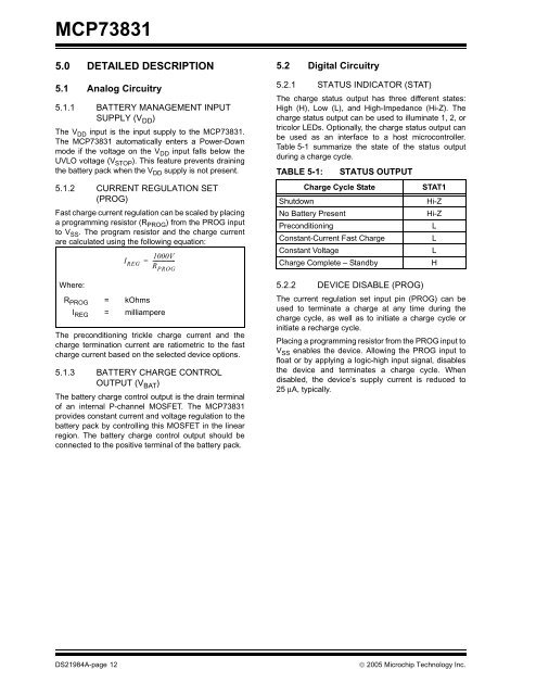
5.0 DETAILED DESCRIPTION<br />
5.1 Analog Circuitry<br />
5.1.1 BATTERY MANAGEMENT INPUT<br />
SUPPLY (V DD )<br />
The V DD input is the input supply to the <strong>MCP73831</strong>.<br />
The <strong>MCP73831</strong> automatically enters a Power-Down<br />
mode if the voltage on the V DD input falls below the<br />
UVLO voltage (V STOP ). This feature prevents draining<br />
the battery pack when the V DD supply is not present.<br />
5.1.2 CURRENT REGULATION SET<br />
(PROG)<br />
Fast charge current regulation can be scaled by placing<br />
a programming resistor (R PROG ) from the PROG input<br />
to V SS . The program resistor and the charge current<br />
are calculated using the following equation:<br />
Where:<br />
I REG<br />
=<br />
1000V<br />
----------------<br />
R PROG<br />
R PROG = kOhms<br />
I REG = milliampere<br />
The preconditioning trickle charge current and the<br />
charge termination current are ratiometric to the fast<br />
charge current based on the selected device options.<br />
5.1.3 BATTERY CHARGE CONTROL<br />
OUTPUT (V BAT )<br />
The battery charge control output is the drain terminal<br />
of an internal P-channel MOSFET. The <strong>MCP73831</strong><br />
provides constant current and voltage regulation to the<br />
battery pack by controlling this MOSFET in the linear<br />
region. The battery charge control output should be<br />
connected to the positive terminal of the battery pack.<br />
5.2 Digital Circuitry<br />
5.2.1 STATUS INDICATOR (STAT)<br />
The charge status output has three different states:<br />
High (H), Low (L), and High-Impedance (Hi-Z). The<br />
charge status output can be used to illuminate 1, 2, or<br />
tricolor LEDs. Optionally, the charge status output can<br />
be used as an interface to a host microcontroller.<br />
Table 5-1 summarize the state of the status output<br />
during a charge cycle.<br />
TABLE 5-1:<br />
STATUS OUTPUT<br />
Charge Cycle State<br />
Shutdown<br />
No Battery Present<br />
Preconditioning<br />
Constant-Current Fast Charge<br />
Constant Voltage<br />
Charge Complete – Standby<br />
STAT1<br />
Hi-Z<br />
Hi-Z<br />
L<br />
L<br />
L<br />
H<br />
5.2.2 DEVICE DISABLE (PROG)<br />
The current regulation set input pin (PROG) can be<br />
used to terminate a charge at any time during the<br />
charge cycle, as well as to initiate a charge cycle or<br />
initiate a recharge cycle.<br />
Placing a programming resistor from the PROG input to<br />
V SS enables the device. Allowing the PROG input to<br />
float or by applying a logic-high input signal, disables<br />
the device and terminates a charge cycle. When<br />
disabled, the device’s supply current is reduced to<br />
25 μA, typically.<br />
DS21984A-page 12<br />
© 2005 Microchip Technology Inc.