Customized Scaffold Fabrication with Solid Free ... - TurkCADCAM.net
Customized Scaffold Fabrication with Solid Free ... - TurkCADCAM.net
Customized Scaffold Fabrication with Solid Free ... - TurkCADCAM.net

You also want an ePaper? Increase the reach of your titles
YUMPU automatically turns print PDFs into web optimized ePapers that Google loves.
US – TURKEY Workshop On Rapid Technologies, September 24 – 24, 2009<br />
<strong>Customized</strong> <strong>Scaffold</strong> <strong>Fabrication</strong> <strong>with</strong> <strong>Solid</strong> <strong>Free</strong> Form Technique<br />
C. Ergun *1 , R. S. Toru 1 , A. Bahadir 1 , S. Yilmaz 1 , S. Basa **2<br />
1 Department of Mechanical Engineering, Faculty of Mechanical Engineering, Istanbul Technical<br />
University, 34437 Istanbul, Turkey<br />
2 Department of Oral and Maxillofacial Surgery, Faculty of Dentistry, Marmara University, 34365<br />
Istanbul, Turkey<br />
(ergunce@itu.edu.tr * , sbasa@marmara.edu.tr ** )<br />
Abstract - Design and fabrication of<br />
customized scaffolds requires a control in the<br />
internal and external geometrical features down to<br />
100 to 1000 µm. Therefore, fabrication of scaffolds<br />
especially made of bioceramic is a challenging<br />
problem in the fabrication. In this work, solid free<br />
form technique was used to fabricate the<br />
customized scaffolds.<br />
Keywords – <strong>Scaffold</strong>, Bioceramics, <strong>Solid</strong> <strong>Free</strong><br />
Form Technique, <strong>Customized</strong> <strong>Scaffold</strong>s.<br />
I. INTRODUCTION<br />
Since biocompatible surfaces are needed for<br />
new bone regeneration, bone cannot deposit or<br />
filled by jump over large empty space during<br />
bone healing process. Therefore, the dimensions<br />
of the cavity that should filled by bone during<br />
the healing becomes very important. The cavity<br />
may be generally filled by graft materials in the<br />
form of granules or scaffolds in medical<br />
operations. <strong>Scaffold</strong>s fabricated considered<br />
design criteria have considerable advantages<br />
over granules.<br />
The primary purposes in scaffolds design in<br />
tissue engineering are to maximize nutrient<br />
diffusion, interstitial fluid and blood flow, to<br />
control cell growth and function, to manipulate<br />
tissue differentiation, and to optimize scaffold<br />
mechanical function and regenerated tissue<br />
mechanical properties. So in the design of an<br />
ideal scaffold that functions to insure the<br />
primary purposes, a control in the architectural<br />
features down to 100 to 1000µm becomes<br />
crucial.<br />
<strong>Solid</strong> free form fabrication technique is one<br />
of the very attractive methods in advanced<br />
ceramic processing enabling to fabricate<br />
ceramic components <strong>with</strong> complex internal and<br />
external architecture designed in CAD<br />
environment [1-3].<br />
The purpose of this study is to develop a<br />
procedure to design customized scaffolds <strong>with</strong><br />
controlled internal and external geometries to<br />
apply on healing for particular patient. A patient<br />
<strong>with</strong> a hemi facial microsomi was chosen as the<br />
case study. In the first, the CT data of the<br />
patients was used to build CAD models of their<br />
defected bone structures. In the second,<br />
appropriate scaffolds was designed in the CAD<br />
environment. In the last, these scaffolds were<br />
fabricated from calcium phosphate bioceramics<br />
<strong>with</strong> solid free form technique. Fabricated<br />
scaffolds were tested by assembling on the 3D<br />
bone model of patient fabricated <strong>with</strong> rapid<br />
prototyping method.<br />
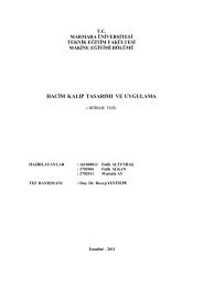
II. METHODOLOGY<br />
A schematic of scaffold fabrication methods<br />
is outlined in Fig. 1. Five steps are involved: (1)<br />
The CT data of the respected patient was needed<br />
to design scaffold in CAD environment, (2)<br />
design of CAD model scaffold and its<br />
corresponding mold; (3) building of the mold<br />
<strong>with</strong> solid ink-jet printing; (4) casting of ceramic<br />
suspension into mold and curing (5) dissolution<br />
of the mold in EtOH; (6) Pirolizing of the binder<br />
and following sintering process.<br />
CT Data of the patient<br />
<strong>Scaffold</strong> andmolddesign<br />
Moldfabrication<br />
Casting/ Curing<br />
Moldremoval<br />
Sintering<br />
Fig. 1. Schematic chart of the fabrication of customized<br />
scaffold via indirect solid freeform procedure.<br />
51
US – TURKEY Workshop On Rapid Technologies, September 24 – 24, 2009<br />
III. RESULTS<br />
Figure 2 shows the patient who has<br />
hemifacial microsomi and its jaw bone<br />
fabricated via rapid prototyping based on his CT<br />
data. The reason of the distortion on his face is<br />
the asymmetry in his jaw.<br />
Fig. 4. Fabricated scaffold<br />
Figure 4 shows the fabricated scaffold via<br />
the procedures given in Figure 1.<br />
(b)<br />
l<br />
Fig. 2. (a) A typical appearance of the patient having<br />
hamifacial microsomi: (b) 3D Model fabricated via rapid<br />
prototyping (δl: the missing distance causing the shortness<br />
of the bone at one side consequently the distortion on the<br />
face)<br />
(a)<br />
IV. DISCUSION<br />
The procedure developed in this study<br />
based on solid freeform technique can<br />
successfully be applied to fabricate customized<br />
scaffolds. Thus, internal and external<br />
architecture convenient to the patient<br />
physiological geometries can be insured <strong>with</strong> a<br />
better accuracy than the treatment using granule<br />
based space filling materials.<br />
ACKNOWLEDGMENT<br />
This research was founded by TUBITAK<br />
(Project # 106M053).<br />
REFERENCES<br />
[1] D. M. Lıu, 1997. <strong>Fabrication</strong> of hydroxyapatite<br />
ceramic <strong>with</strong> controlled porosity, Journal of<br />
Materials Science, 8, 227-232.<br />
Fig. 3. (a) The jaw bone of the patient <strong>with</strong> a missing<br />
geometry to insure the symmetry like in a healthy jaw bone;<br />
(b) CAD modeled a scaffold needed for the treatment.<br />
Figure 3 shows the CAD model of the<br />
scaffold needed to treat this patient.<br />
[2] Cheng Yu Lin, N. Kikuchi, S. J. Hollister, 2004.<br />
A novel method for biomaterial scaffold internal<br />
architecture design to match bone elastic<br />
properties <strong>with</strong> desired porosity, Jounal of<br />
Biomechanics 37, 623-636.<br />
[3] T. M. G. Chu, J. W. Halloran, S. J. Hollister, S.<br />
E. Feinberg, 2001. Hydroxyapatite implants <strong>with</strong><br />
designed internal architecture, Journal of<br />
materials science, 12, 471-478.<br />
[4] S.J. Hollister, R.D. Maddox, J.M. Taboas, 2002.<br />
Optimal design and fabrication of scaffolds to<br />
mimic tissue properties and satisfy biological<br />
constraints, Biomaterials 23, 4095-4103.<br />
52