
Create successful ePaper yourself
Turn your PDF publications into a flip-book with our unique Google optimized e-Paper software.
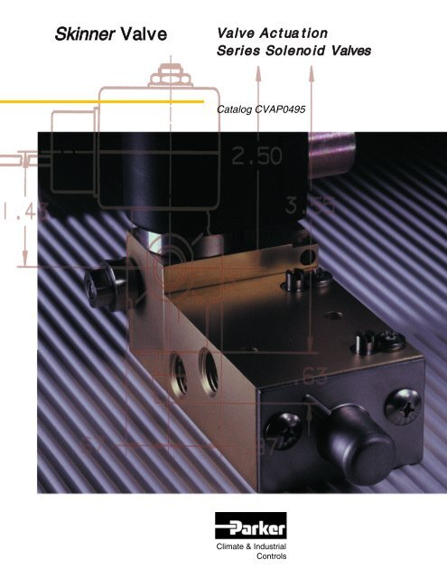
<strong>Skinner</strong> <strong>Valve</strong><br />
<strong>Valve</strong> Ac t ua t ion<br />
Series Soleno id Va l v e s<br />
Catalog CVAP0495<br />
Climate & Industrial<br />
<strong>Co</strong>ntrols
TABLE OF CON T E N T S<br />
INTRODUCTION/1<br />
AVAILABLE VALVE ACTUATION SERIES PRODUCTS/2-3<br />
FEATURES AND BENEFITS/4 - 6<br />
PRODUCT LINE CHART/7<br />
3-WAY SOLENOID VALVES/8-12<br />
7700 Line/9<br />
7300 Line/10<br />
7000 Series/11 -12<br />
4-WAY SOLENOID VALVES/13-16<br />
7700 Line/14<br />
7300 Line/15<br />
7000 Series/16<br />
INTRINSICALLY SAFE SOLENOID VALVES/17-19<br />
I.S. Ordering Information/19<br />
ULTRA LOW-POWER SOLENOID VALVES/20-21<br />
MANUAL RESET SOLENOID VALVES/22-23<br />
DIRECT MOUNT SOLENOID VALVES/24-25<br />
COILS, OPTIONS AND ACCESSORIES/26-32<br />
VALVE ORDERING/33<br />
PART NUMBERING SYSTEM/34-35<br />
ADDITIONAL TECHNICAL INFORMATION/36-44<br />
OUTLINE DRAWINGS/45-52<br />
WARNING<br />
FAILURE OR IMPROPER SELECTION OR IMPROPER USE OF THE PRODUCTS AND/OR SYSTEMS DESCRIBED<br />
HEREIN OR RELATED ITEMS CAN CAUSE DEATH, PERSONAL INJURY AND PROPERTY DAMAGE.<br />
This document and other information from Parker Hannifin <strong>Co</strong>rporation, its subsidiaries and authorized distributors<br />
provide product and/or system options for further investigation by users having technical expertise. It is important that<br />
you analyze all aspects of your application and review the information concerning the product or system in the current<br />
product catalog. Due to the variety of operating conditions and applications for these products or systems, the user,<br />
through its own analysis and testing, is solely responsible for making the final selection of the products and systems and<br />
assuring that all performance, safety and warning requirements of the application are met.<br />
The product described herein, including without limitation, product features, specifications, designs, availability and<br />
pricing, are subject to change by Parker Hannifin <strong>Co</strong>rporation and its subsidiaries at any time without notice.<br />
Offer of Sale<br />
The items described in this document are hereby offered for sale by Parker Hannifin <strong>Co</strong>rporation, its subsidiaries or its<br />
authorized distributors. This offer and its acceptance are governed by the provisions stated on the separate page of this<br />
document entitled “Terms and <strong>Co</strong>nditions of Sale”. (See page 60.)<br />
© <strong>Co</strong>pyright 1998, Parker Hannifin <strong>Co</strong>rporation. All rights reserved.
Solenoid <strong>Valve</strong>s for<br />
Actuator Au t o m a t i o n<br />
<strong>Valve</strong> Actuation Se r i e s<br />
The <strong>Skinner</strong> <strong>Valve</strong> Actuation Series of<br />
solenoid valves includes the new 7700 and<br />
7300 Lines of 3- and 4-way valves, as well<br />
as: All-Ports-In-Body valves; Intrinsically<br />
Safe valves; Quick Exhaust valves; Direct<br />
Mount valves with NAMUR interface;<br />
Ultra Low-Power valves; and a host of accessories and options.<br />
In addition, to satisfy the most stringent environmental demands,<br />
most valves are available in a choice of body materials including<br />
brass, stainless steel, aluminum and others, as well as a variety of<br />
elastomeric seals.<br />
1
Available <strong>Skinner</strong><br />
<strong>Valve</strong> Actuation<br />
S eries Sol e n o i d<br />
Valv e s<br />
The <strong>Skinner</strong> <strong>Valve</strong> Actuation<br />
Series includes a variety of<br />
new 3- and 4-way valves<br />
designed with unique features<br />
and options enhancing their<br />
performance, operational<br />
reliability and application<br />
v e r s a t i l i t y.<br />
The Actuation Series 7300<br />
and 7700 Lines come with<br />
standard features which<br />
include: integral pilot<br />
filtration, captured pusher<br />
cavity exhaust; air- a s s i s t e d<br />
spring return and a tag mount<br />
provision. Also available are<br />
horizontal operators, field<br />
convertible manual overrides,<br />
m o m e n t a ry manual overrides<br />
and captured exhaust pilot.<br />
<strong>Valve</strong> Actuation Series<br />
3- and 4-Way 7700 Line<br />
The 7700 Line of 3- and 4-way<br />
solenoid valves incorporate a<br />
number of unique features including:<br />
captured exhaust pilot; integrated<br />
main exhaust; and integral metering.<br />
They are available in brass, stainless<br />
steel, and aluminum bodies in single<br />
or double solenoid versions and are<br />
also available as externally piloted<br />
valves. There is also a field<br />
convertible manual override option.<br />
<strong>Valve</strong> Actuation Series<br />
3- and 4-Way 7300 Line<br />
The 7300 Line of 3- and 4-way<br />
valves has the same quality of<br />
design and materials found in the<br />
7700 Line. Like the 7700 Line, the<br />
7300 Line includes the following<br />
standard features: integral pilot<br />
filtration; captured pusher cavity<br />
exhaust; air-assisted spring return;<br />
and tag mount provision. They are<br />
available in single and double<br />
solenoid versions and are also<br />
available as externally piloted or<br />
remotely piloted units. There are<br />
also captured exhaust pilot,<br />
momentary manual override and<br />
field convertible manual overrides as<br />
options. They are available in brass,<br />
stainless steel and aluminum bodies.<br />
Actuation Series Standard<br />
3- and 4-Way Va l v e s<br />
Standard 3- and 4-Way A c t u a t i o n<br />
Series valves include a selection of<br />
time proven 7000 Series valves:<br />
Normally Open, Normally Closed,<br />
Multipurpose, Quick Exhaust, A l l -<br />
Ports-In-Body and pilot operated<br />
4-way valves. Most are available in<br />
stainless steel constructions, some<br />
are available in brass or aluminum.<br />
2
Intrinsically Safe<br />
Solenoid Va l v e s<br />
<strong>Skinner</strong> Intrinsically Safe solenoid<br />
valves have been developed for use<br />
in environments where fire and<br />
explosive hazards exist due to the<br />
presence of flammable gases,<br />
vapors, liquids, combustible dusts,<br />
or easily ignitable fibers.<br />
When designed into an<br />
intrinsically safe system, <strong>Skinner</strong><br />
Intrinsically Safe valves provide<br />
low-power consumption, lowtemperature<br />
rise, wide range of sizes<br />
(3- and 4-way configurations),<br />
watertight construction equivalent to<br />
N E M A4, suitable for use with air<br />
and inert gases, and can be mounted<br />
in any position to operate.<br />
Ultra Low-Power<br />
Solenoid Va l v e s<br />
<strong>Skinner</strong> Ultra Low-Power solenoid<br />
valves incorporate a unique operator<br />
designed to keep current draw to a<br />
minimum power consumption level<br />
of 0.6 watts. No refresh time is<br />
r e q u i r e d .<br />
The valves are ideally suited<br />
for use in automated control<br />
systems, applications where<br />
minimizing energy consumption is<br />
critical, or where heat rise in the coil<br />
must be kept to a minimum. T h e s e<br />
devices allow for an increased<br />
number of solenoids to be driven<br />
from the same power source<br />
reducing the overall installation cost.<br />
Ultra Low-Power valves are<br />
available in 3- and 4-way<br />
construction in single or double<br />
solenoid models. <strong>Co</strong>ils are available<br />
in integrated designs in both NEMA<br />
4X and NEMA 4X, 7 and 9<br />
v e r s i o n s .<br />
Manual Reset<br />
Solenoid Va l v e s<br />
<strong>Skinner</strong> Manual Reset valves are<br />
ideally suited for use as a safety<br />
device on valves which, when<br />
triggered, must remain in their “at<br />
rest” position until the reset<br />
mechanism is manually set or<br />
latched. Typical applications include<br />
use in processing, power and<br />
chemical plants.<br />
The Manual Reset option<br />
permits a valve to be tripped either<br />
upon loss of power to the coil or<br />
when power is applied to the coil.<br />
This action is accomplished through<br />
two different types of manual reset<br />
3<br />
configurations; No-Vo l t a g e - R e l e a s e<br />
and Electrically Tr i p p e d .<br />
Direct Mount (NAMUR<br />
Patterned) Solenoid Va l v e s<br />
Honeywell offers NAMUR flange<br />
patterned <strong>Skinner</strong> solenoid valves in<br />
direct acting 3-way, pilot operated<br />
3- and 4-way, single and double<br />
solenoid versions, aluminum and<br />
stainless steel constructions.<br />
Honeywell has one of the broadest<br />
lines of NAMUR-mounted off e r i n g s<br />
in the world.<br />
All 4-way models are<br />
provided with a unique 3-way/4-way<br />
conversion plate. In the 3-way<br />
configuration, the plate channels<br />
return air from the cylinder port to<br />
the spring cavity of the actuator,<br />
substantially prolonging the life of<br />
the actuator.
Features<br />
and Bene f i t s<br />
When Used for<br />
<strong>Co</strong>ntrol of Pneumatic<br />
Actuators, Ac t u a t i o n<br />
Series Solenoid<br />
<strong>Valve</strong>s Prov i d e<br />
Distinct Adva n t a g e s<br />
and Benefits.<br />
Enhanced Reliability of Operation<br />
Because most process applications require the process control valve, and its<br />
controlling solenoid valve, to be exposed to the most severe operating<br />
environments, <strong>Skinner</strong> <strong>Valve</strong> has built into its new Actuation Series 7700<br />
and 7300 Lines a number of specific features which enhance their<br />
performance and operating reliability.<br />
● Unique seal, spool and cage design is ideally suited to meet a wide range of environmental conditions:<br />
temperatures from -40°F (-40°C) to 167°F (75°C); pressure ranges of 30-150 PSI.<br />
● Integral Pilot Filtration–Internally filtered pilot air supply inhibits pilot orifice fouling and further improves<br />
the performance of the valve.<br />
● C o n t a m i n a t i o n - Tolerant Design–Tolerant to entrained pneumatic supply particulates to 40 microns.<br />
● Integrated Main Exhaust (7700 Exclusive)–All air exiting from the valve is channeled through a single<br />
exhaust port. This reduces the number of external openings and minimizes ambient contamination<br />
entering the valve.<br />
● Captured Exhaust Pilot–Eliminates the need to vent pilot exhaust directly to the atmosphere, thus<br />
preventing the entrance of water, ice, bugs, and the like into the pilot chamber and adversely affecting valve<br />
r e l i a b i l i t y.<br />
● Captured Pusher Cavity Exhaust–The Pusher cavity is internally vented to eliminate external contamination<br />
and installation limitations associated with exposed ports/orifices.<br />
● A i r-Assisted Spring Return–Air supplements return spring force on the de-energized (reset) cycle, thus<br />
improving the return stroke reliability.<br />
Ve r s a t i l i t y<br />
Regardless of the environment the valve may be used in, <strong>Skinner</strong> Va l v e<br />
Actuation Series products have the versatility to handle it. The wide selection<br />
of body materials, electrical enclosures, power ratings, and other application<br />
specific features make this series ideal for all process applications.<br />
● Integral Metering (7700 Exclusive)–Independently controls the actuator speed in both directions on 4-way<br />
valves and the actuator return speed on 3-way valves.<br />
● Wide Ambient Temperature Range–Products are available that operate from -40°F (-40°C) to 250°F<br />
( 121 ° C ).<br />
● Body Materials–Available to suit a wide range of exposures including: 316L, 430F and 303 Stainless<br />
Steel; hard-coat anodized low-copper aluminum or brass.<br />
● Wide Pressure Range– From 0 to 215 PSI, the valves are ideally suited for valve actuation.<br />
● Operator Orientation–Available in a variety of configurations to address different spacing and mounting<br />
r e q u i r e m e n t s .<br />
● Mounting <strong>Co</strong>nfiguration–Both pipe mount and direct mount are available.<br />
● Double Solenoids–For “fail as is” applications.<br />
● Multipoised Operator–The solenoid operator may be mounted in any position without affecting valve<br />
p e r f o r m a n c e .<br />
4
● Remotely Piloted–For applications where the electrical portion of the valve is not located at the process<br />
v a l v e .<br />
● Externally Piloted–When the controlled air signal is less than the requirement of the solenoid valve, a<br />
separate air signal can be used to operate the valve.<br />
● Tag Mount Provision–A dedicated feature for ease of installation of a tag.<br />
● Global Porting–Both NPT and BSP porting available.<br />
● Wide Voltage Range–AC units from 24 to 480 volts and DC units from 12 to 125 volts.<br />
● Ultra Low-Power <strong>Co</strong>ils–<strong>Valve</strong>s available down to 0.6 watts.<br />
● Global Approvals–Watertight, explosion proof, Intrinsically Safe, non-incendive, Cenelec and more for use<br />
throughout the world.<br />
● Integrated, Encapsulated <strong>Co</strong>ils–Eliminate the need for separate metal housings while providing a NEMA<br />
4X or NEMA 4X, 7 and 9 rating.<br />
● All Fasteners, Trim and Internal Wetted parts (including springs) are made of corrosion-resistant materials.<br />
Expansive Modularity for Application Flexibility<br />
<strong>Skinner</strong> <strong>Valve</strong> Actuation Series solenoid valves have been developed in a<br />
modular configuration allowing for wide application flexibility. W h e t h e r<br />
pipe mounted or direct mounted to pneumatic actuators, <strong>Skinner</strong> solenoid<br />
valves can be configured to control any process valve equipped with a<br />
pneumatic positioning drive. Features include:<br />
● Field <strong>Co</strong>nvertible Manual Override–A unique construction that allows the device to be converted from a<br />
latching manual override to a momentary manual override or to be locked, thus removing the override<br />
f e a t u r e .<br />
● Multi-Function Direct Mount–With a 3/4-way solenoid valve in NAMUR or customer-specific mounting<br />
flange plate.<br />
● Modular Main Body Architecture–Facilitates use of air pilots (remote or external), single or dual solenoid,<br />
vertical pilot body, and horizontal pilot body.<br />
● AC/DC <strong>Co</strong>mpatible Pressure Ve s s e ls–Pressure vessel can be fitted with either an AC or DC coil, ordinary<br />
or hazardous location construction for added flexibility.<br />
● Interchangeable <strong>Co</strong>il Options–Standard power (10 watts), low-power (1.5 watts), Fluxtron ® E l e c t r o n i c<br />
coils, Magnelatch ® Latching coils, and NEMA 4X and NEMA 7/9 construction.<br />
Whether your application is in chemical or petrochemical processing, power<br />
generation, petroleum refining, pulp and paper production, food and<br />
beverage, water and wastewater treatment, cement and glass manufacturing,<br />
or oil and gas exploration, there is an Actuation Series solenoid valve for<br />
your particular need.<br />
5
Available Options<br />
and Accessories<br />
A variety of options, accessories and coil/enclosure combinations are<br />
available for use with <strong>Skinner</strong> <strong>Valve</strong> Actuation Series solenoid valves.<br />
State-of-the-Art <strong>Co</strong>il Te c h n o l o g y<br />
With application requirements differing for various uses in process<br />
automation, we offer a variety of time proven 7000 Series solenoid coils and<br />
technologies to suit your particular needs, including:<br />
● Integrated, <strong>Co</strong>rrosion Resistant, encapsulated coils which do not require an external housing or yoke.<br />
● Electronic and <strong>Co</strong>nventional coil technology allows for use with electrical signals from control equipment.<br />
● Low-Power Operation (1.5 Watt) and Ultra Low-Power (0.6 Watt) at standard pressure and flow rates so<br />
performance is not compromised.<br />
● Ratings and Approvals include NEMA 4 X ordinary location, NEMA 7/9 hazardous location, Intrinsically<br />
Safe, and non-incendive.<br />
Additional Application Specific Features<br />
Additional features and options available for <strong>Skinner</strong> Actuation Series<br />
solenoid valves include:<br />
● Manual Override to operate a valve without electrical power, to facilitate start-up procedures, and to perform<br />
diagnostic checks. This option is available in momentary, latching or field convertible versions.<br />
● Spring Cavity Purge (3/2 function) with return air channeled from the actuator’s piston side to the spring<br />
side on the spring stroke, thus prolonging the life of the actuator.<br />
● Full Range Hazardous Location Approval Class I, Div. I, Groups A, B, C, D; Class II, Div. I, Groups E, F, G;<br />
Class III, Div. I.<br />
● A range of accessories including: quick exhaust modules, exhaust adaptors, manual overrides and pilot<br />
g u a r d .<br />
New High-Flow Solenoid Va l v e s<br />
For high-flow applications (4.0 Cv), <strong>Skinner</strong> <strong>Valve</strong> Actuation Series includes<br />
a number of three-way and four-way valves, as well as Ultra-Low Power<br />
valves and Intrinsically Safe solenoid valves.<br />
Further Product Information<br />
Detailed product information and specifications on Parker’s <strong>Skinner</strong> Va l v e<br />
Actuation Series solenoid valves for process control can be found within this<br />
catalog. For additional information, contact our product application department<br />
at (860) 827-2300 or write Parker Hannifin <strong>Co</strong>rporation, <strong>Skinner</strong> Va l v e<br />
Division, 95 Edgewood Avenue, New Britain, CT 06051 .<br />
6
Product Type<br />
PRODUCT LINE<br />
C ATALOG SECTION<br />
Intrinsically Ultra<br />
7700 Line 7300 Line 7000 Series 3-Way 4-Way Safe Low-Power Manual Reset Direct Mount<br />
3-Way A A A – A A A A<br />
4-Way A A A – A A A A<br />
Intrinsically Safe A – A<br />
Ultra Low-Power A –<br />
Manual Reset A A A –<br />
Direct Mount (NAMUR Patterned) A A A A A –<br />
High Flow (4.0 C v ) A A A<br />
Mechanical Features<br />
Integral Pilot Filtration S S A A A A A A<br />
Integrated Main Exhaust S A A A A A A<br />
Captured Exhaust Pilot S A A A A<br />
Pilot Guard A A A A A A A<br />
Captured Pusher Cavity Exhaust S S A A A A A A<br />
Air-Assisted Spring Return S S A A A A A A A<br />
Integral Metering S A A A<br />
Low Temperature (-40°F) S A A A A<br />
Body Brass A A A A A A A A A<br />
Materials Stainless Steel A A A A A A A A A<br />
Aluminum(*= Hard <strong>Co</strong>at) A* A* A A A* A*<br />
Single Solenoid A A A A A A A A A<br />
Double Solenoid A A A A A A<br />
Remotely Piloted A A A<br />
Externally Piloted A A A A<br />
Tag Mount Provision S S A A A A A A<br />
Manual Momentary A A A A A A A<br />
Overrides Latching A A A<br />
Field <strong>Co</strong>nvertible A A A A A A A<br />
Spring Cavity Purge A A A A A<br />
Electrical Features<br />
Power<br />
Ratings <strong>Co</strong>nsumption<br />
Integrated NEMA4X 22 A A A A<br />
<strong>Co</strong>ils 10 A A A A A A A<br />
1.5 A A A A A<br />
0.6 A A<br />
NEMA4X, 22 A A A A<br />
7, 9 10 A A A A A A A<br />
1.5 A A A A A<br />
0.6 A A<br />
Specialty Fluxtron 1.3 A A A A A A<br />
<strong>Co</strong>ils Magnelatch 0 A A A A A A<br />
A-A vailable, S- Standard<br />
7
T h r e e - Way<br />
Va l v e s<br />
<strong>Skinner</strong> <strong>Valve</strong><br />
Actuation Series<br />
T h r e e-Way<br />
Solenoid <strong>Valve</strong>s<br />
<strong>Skinner</strong> three-way solenoid valves are ideally suited to control single-acting,<br />
spring return, pneumatic actuators and cylinders. Parker offers a variety of<br />
valve models in the 7300 and 7700 Lines and standard solenoid valves that<br />
a fford the end user greater flexibility in selecting the optimum design to<br />
satisfy the application requirements.<br />
With port sizes ranging from 1/4” to 3/4” NPT, the valves are<br />
available in normally open, normally closed, and multipurpose configurations.<br />
Depending on the model selected, orifice sizes from 1/16” to 3/4”<br />
provide flow factors (Cv) from 0.095 to 7.3 with operating pressure<br />
d i fferentials of 0 to 215 PSI. To ensure proper system response, the valve<br />
orifice size, corresponding Cv flow factor and system pressure can be<br />
matched to the actuator to produce the desired opening and closing speeds.<br />
<strong>Co</strong>nstructed of brass or stainless steel, maximum environmental protection<br />
and corrosion resistance is assured.<br />
8
770 0<br />
SKINNER 7700<br />
LINE FEATURES<br />
Standard Features<br />
● Unique Seal, Spool and Cage<br />
D e s i g n<br />
● Integral Pilot Filtration<br />
● <strong>Co</strong>ntamination Tolerant Design<br />
● Integrated Main Exhaust<br />
● Captured Exhaust Pilot<br />
● Captured Pusher Cavity Exhaust<br />
● A i r-Assisted Spring Return<br />
● Integral Metering<br />
● Tag Mount Provision<br />
● 1.5 Watt Power Level<br />
Optional Features<br />
● Horizontal Oriented Solenoid<br />
O p e r a t o r s<br />
● Field <strong>Co</strong>nvertible Manual Override<br />
SPECIFICATIONS<br />
Mechanical Characteristics<br />
Standard Materials of <strong>Co</strong>nstruction<br />
● B o dy–Brass or 303 Stainless Steel<br />
● S e a ls– N B R<br />
● S p o ol–T h e r m o p l a s t i c<br />
● C a g es– T h e r m o p l a s t i c<br />
● Sleeve Tu be–Stainless Steel (304)<br />
● P l u n g er–Stainless Steel (430 F)<br />
● S t op–Stainless Steel (430 F)<br />
● S p r i n gs–Stainless Steel (18-8 or 17-4)<br />
● M e t e r i n g<br />
S t em–Stainless Steel (303)<br />
S h u t t er–Stainless Steel (303)<br />
Set Screw–Stainless Steel (300 Series)<br />
● F i l t er–P o l y e t h y l e n e<br />
<strong>Co</strong>mpatible Fluids<br />
● Lubricated A i r, Non-Lubricated A i r, Inert<br />
Gases and other gases compatible with<br />
materials of construction.<br />
Electrical Characteristics<br />
Vo l t a g e s<br />
● DC–12, 24, 48<br />
● AC–24/50/60, 110/50-120/60,<br />
220/50-240/60<br />
(other voltages available upon request)<br />
Electrical <strong>Co</strong>nnections<br />
● Leaded, 1/2” <strong>Co</strong>nduit, DIN, Screw, Ta b<br />
Agency Approvals<br />
● U L approvals are available on valves with<br />
applicable coil/enclosure combinations.<br />
For additional information see pages 40-41 .<br />
M i s c e l l a n e o u s<br />
Minimum Ambient Te m p e r a t u r e<br />
● -4 0 ° F ( - 4 0 ° C )<br />
Dew point must be more than 7°F below<br />
a m b i e n t .<br />
Maximum Ambient Te m p e r a t u r e<br />
● 1.5 Watt AC–150°F (65°C)<br />
● 10 Watt A C / DC–167°F (75°C)<br />
● F l u x t r o n / M a g n e l a t h–1 c 22 ° F ( 50 ° C )<br />
Maximum Fluid Te m p e r a t u r e<br />
● 167°F (75°C)<br />
Mounting Position<br />
● Multipoised–valves may be installed in<br />
any position.<br />
SKINNER 7700 LINE THREE-WAY VA LV E S<br />
Operating Pressure Differential (PSI)<br />
Pipe Orifice C v Maximum Brass Stainless Steel<br />
Size Size Flow AC DC Pressure Vessel Pressure Vessel <strong>Co</strong>nstr.<br />
(NPT) (Inches) Factor Min 1.5 watt 10 watt 10 watt Catalog Number Catalog Number Ref.<br />
7700 Line<br />
1/4” 11/64 0.55 30 150 150 150 77317BN2KN7M 77317VN2KN7M 1<br />
1/4 1.2 30 150 150 150 77317BN2PN7M 77317VN2PN7M 1<br />
7700 Line–External Pilot*<br />
1/4” 11/64 0.55 0 150 150 150 78317BN2KN7M 78317VN2KN7M 2<br />
1/4 1.2 0 150 150 150 78317BN2PN7M 78317VN2PN7M 2<br />
* External pilot pressure to operate valve must be 30-150 PSI.<br />
9
7300<br />
SKINNER 7300<br />
LINE FEATURES<br />
Standard Features<br />
• Unique Seal, Spool and Cage Design<br />
• Integral Pilot Filtration<br />
• <strong>Co</strong>ntamination Tolerant Design<br />
• Captured Pusher Cavity Exhaust<br />
• A i r-Assisted Spring Return<br />
• Tag Mount Provision<br />
• 1.5 Watt Power Level<br />
Optional Features<br />
• Captured Exhaust Pilot<br />
• Horizontal Oriented Solenoid Operators<br />
• M o m e n t a ry or Field <strong>Co</strong>nvertible<br />
Manual Overrides<br />
• Exhaust Adaptors<br />
SPECIFICATIONS<br />
Mechanical Characteristics:<br />
Standard Materials of <strong>Co</strong>nstruction<br />
● B o dy–Brass or 303 Stainless Steel<br />
● S e a ls–N B R<br />
● S p o ol–T h e r m o p l a s t i c<br />
● C a g es–T h e r m o p l a s t i c<br />
● Sleeve Tu be–Stainless Steel (304)<br />
● P l u n g er–Stainless Steel (430 FR)<br />
● S t op–Stainless Steel (430 FR)<br />
● S p r i n gs–Stainless Steel (18-8 or 17-4)<br />
● F i l t er–P o l y e t h y l e n e<br />
<strong>Co</strong>mpatible Fluids<br />
● Lubricated A i r, Non-Lubricated A i r, Inert<br />
Gases and other gases compatible with<br />
materials of construction.<br />
Electrical Characteristics<br />
Vo l t a g e s<br />
● DC–12, 24, 48<br />
● AC–24/60, 110/50-120/60, 220/50-240/60<br />
(other voltages available upon request).<br />
Electrical <strong>Co</strong>nnections<br />
● Leaded, 1/2” <strong>Co</strong>nduit, DIN, Screw, Ta b<br />
Agency Approvals<br />
● U L approvals are available on valves with<br />
applicable coil/enclosure combinations.<br />
For additional information see pages 40-41 .<br />
M i s c e l l a n e o u s<br />
Minimum Ambient Te m p e r a t u r e<br />
● -4 0 ° F (-4 0 ° C )<br />
Dew point must be more than 7°F below<br />
a m b i e n t .<br />
Maximum Ambient Te m p e r a t u r e<br />
● 1.5 Wa tt–150°F (65°C)<br />
● 10 Wa tt–167°F (75°C)<br />
● F l u x t r o n / M a g n e l a t h–1 c 22 ° F ( 50 ° C )<br />
Maximum Fluid Te m p e r a t u r e<br />
● 167°F (75°C)<br />
Mounting Position<br />
● M u l t i p o i s ed–valves may be installed in<br />
any position.<br />
SKINNER 7300 LINE THREE-WAY VA LV E S<br />
Operating Pressure Differential (PSI)<br />
Pipe Orifice C v Maximum Brass Stainless Steel<br />
Size Size Flow AC DC Pressure Vessel Pressure Vessel <strong>Co</strong>nstr.<br />
(NPT) (Inches) Factor Min 1.5 watt 10 watt 1.5 watt 10 watt Catalog Number Catalog Number Ref.<br />
7300 Line<br />
1/4” 11/64 0.55 30 150 150 150 150 73317BN2KN00 73317VN2KN00 3<br />
1/4 1.2 30 150 150 150 150 73317BN2PN00 73317VN2PN00 3<br />
7300 Line–External Pilot*<br />
1/4” 11/64 0.55 0 150 150 150 150 74317BN2KN00 74317VN2KN00 4<br />
1/4 1.2 0 150 150 150 150 74317BN2PN00 74317VN2PN00 4<br />
7300 Line– 4.0 Cv, Single Solenoid<br />
1/2” 5/8 4.0 30 150 150 150 150 73317BN4UN00 - 29A<br />
7300 Line–4.0 Cv, External Pilot<br />
1/2” 5/8 4.0 30 150 150 150 150 74317BN4UN00 - 29A<br />
7300 Line–4.0 Cv, Remote Pilot<br />
1/2” 5/8 4.0 30 150 150 150 150 75317BN4UN00 - 29A<br />
Operating Pressure Differential (PSI)<br />
Pipe Orifice C v Brass Stainless Steel<br />
Size Size Flow Pressure Vessel Pressure Vessel <strong>Co</strong>nstr.<br />
(NPT) (Inches) Factor Min Maximum Catalog Number Catalog Number Ref.<br />
7300 Line-Remote Operate**<br />
1/4” 11/64 0.55 30 150 75317BN2KN00 5<br />
1/4 1.2 30 150 75317BN2PN00 5<br />
* External pilot pressure to operate valve must be 30-150 PSI. **Remote pilot pressure to operate valve = 35 PSI + .2 (main line pressure)<br />
1 0
7000<br />
SPECIFICATIONS<br />
Mechanical Characteristics<br />
Standard Materials of <strong>Co</strong>nstruction<br />
● B o dy–Brass or Stainless Steel (303 or<br />
4 3 0 F )<br />
● S e a ls–NBR, FKM<br />
● Sleeve Tu be–Stainless Steel (304)<br />
● P l u n g er–Stainless Steel (430 FR)<br />
● S t op–Stainless Steel (430 FR)<br />
● S p r i n gs–Stainless Steel (18-8)<br />
● Shading Ring–C o p p e r<br />
<strong>Co</strong>mpatible Fluids<br />
● Lubricated A i r, Non-Lubricated A i r, Inert<br />
Gases, Wa t e r, Hydraulic Fluids, Petroleum<br />
Products and additional fluids compatible<br />
with materials of construction.<br />
Electrical Characteristics<br />
Vo l t a g e s<br />
● DC–12, 24, 48<br />
● AC–24/60, 110/50-120/60, 220/50-240/60<br />
(other voltages available upon request)<br />
Electrical <strong>Co</strong>nnections<br />
● Leaded, 1/2” <strong>Co</strong>nduit, DIN, Screw, Ta b<br />
Agency Approvals<br />
● U L approvals are available on valves with<br />
applicable coil/enclosure combinations.<br />
For additional information see pages 40-41 .<br />
M i s c e l l a n e o u s<br />
Maximum Ambient Te m p e r a t u r e<br />
● 10 Wa tt–150°F (65°C)<br />
● 22 Wa tt–77°F (25°C)<br />
● F l u x t r o n / M a g n e l a t ch–122°F (50°C)<br />
Mounting Position<br />
● M u l t i p o i s ed–valves may be installed in<br />
any position.<br />
Maximum Fluid Te m p e r a t u r e<br />
● Class F coils–185°F (85°C)<br />
● Maximum fluid temperatures are provided<br />
for Class F coils. <strong>Valve</strong>s with FKM seals<br />
(letter “V” in 10th position of pressure<br />
vessel number) can be used at fluid<br />
temperatures up to 240°F (115°C) on DC<br />
and 250°F (120°C) on AC provided a<br />
Class H coil is used.<br />
SKINNER 7000 SERIES THREE-WAY VA LV E S<br />
Operating Pressure Differential (PSI)<br />
Pipe Orifice C v Maximum Brass Stainless Steel<br />
Size Size Flow AC DC Pressure Vessel Pressure Vessel <strong>Co</strong>nstr.<br />
(NPT) (Inches) Factor Min 10 watt 22 watt 10 watt Catalog Number Catalog Number Ref.<br />
Normally Closed<br />
1/8” 1/16 0.11 0 215 215 7131KBN1GV00 6<br />
3/32 0.24 0 100 100 7131KBN1LV00 6<br />
1/4” 1/16 0.11 0 215 215 7131KBN2GV00 6<br />
1/16 0.11x 0.095 0 200 200 71315SN2GNJ1 7<br />
3/32 0.17 0 125 125 71315SN2KNJ1 7<br />
5/64 .17x .24 0 150 150 7131KBN2JV00 6<br />
3/32 0.24 0 100 100 7131KBN2LV00 6<br />
3/8” 3/8 2.1 10 180 180 73312BN3RNJ1 9<br />
1/2” 1/2 3.6 10 180 180 73312BN4UNJ1 9<br />
3/4” 3/4 7.3 10 180 180 73312BN52NJ1 9<br />
<strong>Co</strong>ntinues on next page.<br />
1 1
SKINNER 7000 SERIES THREE-WAY VA LV E S<br />
Operating Pressure Differential (PSI)<br />
Pipe Orifice C v Maximum Brass Stainless Steel<br />
Size Size Flow AC DC Pressure Vessel Pressure Vessel <strong>Co</strong>nstr.<br />
(NPT) (Inches) Factor Min 10 watt 22 watt 10 watt Catalog Number Catalog Number Ref.<br />
Normally Open<br />
1/8” 1/16x 1/8 0.10x 0.28 0 150 150 71395SN1GVJ1 7<br />
3/32x 1/8 0.17x 0.28 0 125 125 71395SN1KVJ1 7<br />
1/4” 1/16x 1/8 0.10x 0.28 0 150 150 71395SN2GNJ1 7<br />
1/16x 1/8 0.10x 0.28 0 150 150 71395SN2GVJ1 7<br />
3/32x 1/8 0.17x 0.28 0 125 125 71395SN2KNJ1 7<br />
3/8” 3/8 2.1 10 180 180 73322BN3RNJ1 9<br />
3/8 2.1 10 180 180 73382BN3RNJ1 9<br />
1/2” 1/2 3.6 10 180 180 73322BN4UNJ1 9<br />
3/4” 3/4 7.3 10 180 180 73322BN52NJ1 9<br />
Multipurpose<br />
1/8” 1/16 0.11 0 150 150 7133KBN1GVJ1 6<br />
5/64 0.15 0 100 100 7133KBN1JVJ1 6<br />
1/4” 3/64 0.052 0 180 180 71335SN2ENJ1 7<br />
1/16 0.095 0 115 115 71335SN2GNJ1 7<br />
1/16 0.11 0 150 150 7133KBN2GVJ1 6<br />
5/64 0.15 0 100 100 7133KBN2JVJ1 6<br />
3/32 0.17 0 80 80 71335SN2KNJ1 7<br />
3/32 0.24 0 60 60 7133KBN2LVJ1 6<br />
All-Ports-In-Body, Normally Closed<br />
1/4” 1/16 0.095 0 200 200 7131TVN2GV00 10<br />
5/64 0.14 0 150 150 7131TVN2JV00 10<br />
5/6x 1/8 0.14x 0.31 0 150 150 7131TBN2JV00 11<br />
3/32 0.19 0 120 120 7131TVN2LV00 10<br />
3/32x 9/64 0.19x 0.38 0 120 120 7131TBN2LV00 11<br />
1/8 0.31 0 70 70 7131TVN2NV00 10<br />
1/4 .49x .63 0 30 30 7131TBN2RV00 11<br />
All-Ports-In-Body, Normally Open<br />
1/4” 5/32x 1/8 0.41x 0.31 0 150 7132TBN2NV00 11<br />
All-Ports-In-Body, Multipurpose<br />
1/4” 1/16 0.095 0 150 150 7133TVN2GV00 10<br />
5/64 0.17 0 100 100 7133TBN2JV00 11<br />
5/64 0.18 0 100 100 7133TVN2JV00 10<br />
1/8 0.31 0 30 30 7133TBN2NV00 11<br />
1/8 0.32 0 30 30 7133TVN2NV00 10<br />
Normally Closed,Quick Exhaust*<br />
1/4” 3/32x 1/8 0.11x 0.35 0 125 125 71313SN2KNJ1 8<br />
1/4 0.2x 1.1 0 100 100 7131EBN2LN00 12<br />
*The valves operate at 0 PSI, however a 2 PSI minimum pressure differential is required to actuate the pressure operated quick exhaust poppet.<br />
1 2
F o u r- Way<br />
Va l v e s<br />
<strong>Skinner</strong> <strong>Valve</strong><br />
Actuation Series<br />
F o u r-Way<br />
Solenoid <strong>Valve</strong>s<br />
<strong>Skinner</strong> four-way solenoid valves are ideal for use in controlling double<br />
acting, pneumatic actuators or cylinders. Two-position, single or double<br />
solenoid models are designed for long, trouble-free life, and are available in<br />
7700 Line, 7300 Line, and standard solenoid valves.<br />
F o u r-way 7700 and 7300 Line valves have many of the same standard<br />
features found in the line’s three-way valves, including a unique seal, spool<br />
and cage design, integral pilot filtration and contamination tolerant design.<br />
They are available in brass or 303 stainless steel body materials. <strong>Skinner</strong><br />
7000 Series four-way valves are available in aluminum body material.<br />
These four-way valves have a maximum pressure differential of 150 PSI,<br />
with a Cv flow factor of 0.55 or 1.2 for 7700 and 7300 Line valves and<br />
0.35, 1 or 1.4 for 7000 Series valves.<br />
1 3
7700<br />
SKINNER 7700<br />
LINE FEATURES<br />
Standard Features<br />
● Unique Seal, Spool and Cage<br />
D e s i g n<br />
● Integral Pilot Filtration<br />
● <strong>Co</strong>ntamination Tolerant Design<br />
● Integrated Main Exhaust<br />
● Captured Exhaust Pilot<br />
● Captured Pusher Cavity Exhaust<br />
● A i r-Assisted Spring Return<br />
● Integral Metering<br />
● Tag Mount Provision<br />
● 1.5 Watt Power Level<br />
Optional Features<br />
● Horizontal Oriented Solenoid<br />
O p e r a t o r s<br />
● Field <strong>Co</strong>nvertible Manual Override<br />
SPECIFICATIONS<br />
Mechanical Characteristics<br />
Standard Materials of <strong>Co</strong>nstruction<br />
● B o dy–Brass or 303 Stainless Steel<br />
● S e a ls– N B R<br />
● S p o ol–T h e r m o p l a s t i c<br />
● C a g es– T h e r m o p l a s t i c<br />
● Sleeve Tu be–Stainless Steel (304)<br />
● P l u n g er–Stainless Steel (430 FR)<br />
● S t op–Stainless Steel (430 FR)<br />
● S p r i n gs–Stainless Steel (18-8 or 17-4)<br />
● M e t e r i n g<br />
S t em–Stainless Steel (303)<br />
S h u t t er–Stainless Steel (303)<br />
Set Screw–Stainless Steel (300 Series)<br />
● F i l t er–P o l y e t h y l e n e<br />
<strong>Co</strong>mpatible Fluids<br />
● Lubricated A i r, Non-Lubricated A i r, Inert<br />
Gases and other gases compatible with<br />
materials of construction.<br />
Electrical Characteristics<br />
Vo l t a g e s<br />
● DC–12, 24, 48<br />
● AC–24/50/60, 110/50-120/60,<br />
2 2 0 / 5 0 - 2 4 0 / 6 0<br />
(other voltages available upon request)<br />
Electrical <strong>Co</strong>nnections<br />
● Leaded, 1/2” <strong>Co</strong>nduit, DIN, Screw, Ta b<br />
Agency Approvals<br />
● U L approvals are available on valves with<br />
applicable coil/enclosure combinations.<br />
For additional information see pages 40-41 .<br />
M i s c e l l a n e o u s<br />
Minimum Ambient Te m p e r a t u r e<br />
● -4 0 ° F ( - 4 0 ° C )<br />
Dew point must be more than 7°F below<br />
a m b i e n t .<br />
Maximum Ambient Te m p e r a t u r e<br />
● 1.5 Watt AC–150°F (65°C)<br />
● 10 Watt A C / DC–167°F (75°C)<br />
● F l u x t r o n / M a g n e l a t ch–1 2 2 ° F ( 5 0 ° C )<br />
Maximum Fluid Te m p e r a t u r e<br />
● 167°F (75°C)<br />
Mounting Position<br />
● M u l t i p o i s ed–valves may be installed in<br />
any position.<br />
SKINNER 7700 LINE FOUR-WAY VA LV E S<br />
Operating Pressure Differential (PSI)<br />
Pipe Orifice C v Maximum Brass Stainless Steel<br />
Size Size Flow AC DC Pressure Vessel Pressure Vessel <strong>Co</strong>nstr.<br />
(NPT) (Inches) Factor Min. 1.5 watt 10 watt 10 watt Catalog Number Catalog Number Ref.<br />
7700 Line<br />
1/4” 11/64 0.55 30 150 150 150 77417BN2KN7M 77417VN2KN7M 1<br />
1/4 1.2 30 150 150 150 77417BN2PN7M 77417VN2PN7M 1<br />
7700 Line– Double Solenoid<br />
1/4” 11/64 0.55 30 150 150 150 77477BN2KN7M 77477VN2KN7M 13<br />
1/4 1.2 30 150 150 150 77477BN2PN7M 77477VN2PN7M 13<br />
7700 Line– External Pilot*<br />
1/4” 11/64 0.55 0 150 150 150 78417BN2KN7M 78417VN2KN7M 2<br />
1/4 1.2 0 150 150 150 78417BN2PN7M 78417VN2PN7M 2<br />
* External pilot pressure to operate valve must be 30-150 PSI.<br />
1 4
7300<br />
SKINNER 7300<br />
LINE FEATURES<br />
Standard Features<br />
• Unique Seal, Spool and Cage Design<br />
• Integral Pilot Filtration<br />
• <strong>Co</strong>ntamination Tolerant Design<br />
• Captured Pusher Cavity Exhaust<br />
• A i r-Assisted Spring Return<br />
• Tag Mount Provision<br />
• 1.5 Watt Power Level<br />
Optional Features<br />
• Captured Exhaust Pilot<br />
• Horizontal Oriented Solenoid Operators<br />
• M o m e n t a ry or Field <strong>Co</strong>nvertible<br />
Manual Overrides<br />
• Exhaust Adaptors<br />
SPECIFICATIONS<br />
Mechanical Characteristics<br />
Standard Materials of <strong>Co</strong>nstruction<br />
● B o dy–Brass or 303 Stainless Steel<br />
● S e a ls– N B R<br />
● S p o ol–T h e r m o p l a s t i c<br />
● C a g es– T h e r m o p l a s t i c<br />
● Sleeve Tu be–Stainless Steel (304)<br />
● P l u n g er–Stainless Steel (430 FR)<br />
● S t op–Stainless Steel (430 FR)<br />
● S p r i n gs–Stainless Steel (18-8 or 17-4)<br />
● F i l t er–P o l y e t h y l e n e<br />
<strong>Co</strong>mpatible Fluids<br />
● Lubricated A i r, Non-Lubricated A i r, Inert<br />
Gases and other gases compatible with<br />
materials of construction.<br />
Electrical Characteristics<br />
Vo l t a g e s<br />
● DC–12, 24, 48<br />
● AC–24/60, 11 0 / 50-120/60, 220/50-240/60<br />
(other voltages available upon request)<br />
Electrical <strong>Co</strong>nnections<br />
● Leaded, 1/2” <strong>Co</strong>nduit, DIN, Screw, Ta b<br />
Agency Approvals<br />
● U L approvals are available on valves with<br />
applicable coil/enclosure combinations.<br />
For additional information see pages 40-41 .<br />
M i s c e l l a n e o u s<br />
Minimum Ambient Te m p e r a t u r e<br />
● -4 0 ° F (-4 0 ° C )<br />
Dew point must be more than 7°F below<br />
a m b i e n t .<br />
Maximum Ambient Te m p e r a t u r e<br />
● 1.5 Wa tt–150°F (65°C)<br />
● 10 Wa tt–167°F (75°C)<br />
● F l u x t r o n / M a g n e l a t ch–1 2 2 ° F ( 5 0 ° C )<br />
Maximum Fluid Te m p e r a t u r e<br />
● 167°F (75°C)<br />
Mounting Position<br />
● M u l t i p o i s ed–valves may be installed in<br />
any position.<br />
SKINNER 7300 LINE FOUR-WAY VA LV E S<br />
Operating Pressure Differential (PSI)<br />
Pipe Orifice C v Maximum Brass Stainless Steel<br />
Size Size Flow AC DC Pressure Vessel Pressure Vessel <strong>Co</strong>nstr.<br />
(NPT) (Inches) Factor Min. 1.5 watt 10 watt 1.5 watt 10 watt Catalog Number Catalog Number Ref.<br />
7300 Line<br />
1/4” 11/64 0.55 30 150 150 150 150 73417BN2KN00 73417VN2KN00 3<br />
1/4 1.2 30 150 150 150 150 73417BN2PN00 73417VN2PN00 3<br />
7300 Line–Double Solenoid<br />
1/4” 11/64 0.55 30 150 150 150 150 73477BN2KN00 73477VN2KN00 14<br />
1/4 1.2 30 150 150 150 150 73477BN2PN00 73477VN2PN00 14<br />
7300 Line– External Pilot*<br />
1/4” 11/64 0.55 0 150 150 150 150 74417BN2KN00 74417VN2KN00 4<br />
1/4 1.2 0 150 150 150 150 74417BN2PN00 74417VN2PN00 4<br />
7300 Line–4.0 Cv, Single Solenoid<br />
1/2” 5/8 4.0 30 150 150 150 150 73417BN4UN00 - 29A<br />
7300 Line–4.0 Cv, Double Solenoid<br />
1/2” 5/8 4.0 30 150 150 150 150 73477BN4UN00 - 29A<br />
7300 Line–4.0 Cv, Single Solenoid External Pilot<br />
1/2” 5/8 4.0 30 150 150 150 150 74417BN4UN00 - 29A<br />
7300 Line– 4.0 Cv, Single Solenoid Remote Pilot<br />
1/2” 5/8 4.0 30 150 150 150 150 75417BN4UN00 - 29A<br />
Operating Pressure Differential (PSI)<br />
Pipe Orifice C v Brass Stainless Steel<br />
Size Size Flow Pressure Vessel Pressure Vessel <strong>Co</strong>nstr.<br />
(NPT) (Inches) Factor Min Maximum Catalog Number Catalog Number Ref.<br />
7300 Line–Remote Operate**<br />
1/4” 11/64 0.55 30 150 75417BN2KN00 5<br />
1/4 1.2 30 150 75417BN2PN00 5<br />
*External pilot pressure to operate valve must be 30-150 PSI. * *Remote pilot pressure to operate valv e = 35 PSI+ .2 (main line pressure)<br />
1 5
7000<br />
SPECIFICATIONS<br />
Mechanical Characteristics<br />
Standard Materials of <strong>Co</strong>nstruction<br />
● B o dy–A l u m i n u m<br />
● S e a ls–N B R<br />
● S p o ol–A l u m i n u m<br />
● Sleeve Tu be–Stainless Steel (304)<br />
● P l u n g er–Stainless Steel (430 FR)<br />
● S t op–Stainless Steel (430 FR)<br />
● S p r i n gs–Stainless Steel (18-8)<br />
● Shading Ring–C o p p e r<br />
<strong>Co</strong>mpatible Fluids<br />
● Lubricated A i r, Non-Lubricated A i r,<br />
Inert Gases<br />
Electrical Characteristics:<br />
Vo l t a g e s<br />
● DC–12, 24, 48<br />
● AC–24/60, 110/50-120/60, 220/50-240/60<br />
(other voltages available upon request)<br />
Electrical <strong>Co</strong>nnections<br />
● Leaded, 1/2” <strong>Co</strong>nduit, DIN, Screw, Ta b<br />
Agency Approvals<br />
● U L approvals are available on valves with<br />
applicable coil/enclosure combinations.<br />
For additional information see pages 40-4 1 .<br />
M i s c e l l a n e o u s<br />
Maximum Ambient Te m p e r a t u r e<br />
● 10 Wa tt–150°F (65°C)<br />
● F l u x t r o n / M a g n e l a t ch–122°F (50°C)<br />
Mounting Position<br />
● M u l t i p o i s ed–valves may be installed in<br />
any position.<br />
Maximum Fluid Te m p e r a t u r e<br />
● 167°F (75°C)<br />
SKINNER 7000 SERIES FOUR-WAY VA LV E S<br />
Operating Pressure Differential (PSI)<br />
Pipe Orifice C v Maximum Aluminum<br />
Size Size Flow AC DC Pressure Vessel <strong>Co</strong>nstr.<br />
(NPT) (Inches) Factor Min. 10 watt 10 watt Catalog Number Ref.<br />
4-Way<br />
1/8” 5/32 0.35 15 150 150 7341LAN1HNM0 15<br />
1/4” 15/64 1 30 150 150 73419AN2NN00 16<br />
15/64 1 30 150 150 73419AN2NNM0 16<br />
5/16 1.4 15 150 150 7341LMN2NNM0 17<br />
1 6
Intrinsically Safe<br />
Va l v e s<br />
<strong>Skinner</strong><br />
I n t r i nsically Safe<br />
Solenoid <strong>Valve</strong> s<br />
<strong>Skinner</strong> <strong>Valve</strong> has long served industry with innovative valve solutions and<br />
safety related products. <strong>Skinner</strong> Intrinsically Safe solenoid valves are<br />
specifically designed for use in hazardous locations where fire or explosion<br />
hazards exist due to the presence of flammable gases, vapors, liquids,<br />
combustible dust, or easily ignitable fibers or flyings.<br />
When used in conjunction with approved safety barriers, <strong>Skinner</strong><br />
Intrinsically Safe valves have Factory Mutual Research and Canadian<br />
Standards Association approval for locations classified as Class I, Division<br />
I, Groups A, B, C, D; Class II, Division I, Groups E, F, G; and Class III,<br />
Division I. As part of an intrinsically safe system, the valves are incapable<br />
of causing explosive atmospheres to ignite by spark or thermal effect during<br />
normal operation or under fault conditions.<br />
The three-way valves are offered as normally closed or multipurpose,<br />
while the four-way valves are two-position, single or double solenoid.<br />
Six special purpose valves are also in our portfolio. Five designs<br />
with NAMUR interface can be mounted directly to actuators to save<br />
installation cost. ANo-Voltage-Release manual reset device is available for<br />
applications where human interaction is required to ensure the highest<br />
degree of safety.<br />
1 7
I ntri n s i c a l l y<br />
Safe Va l v e s<br />
SPECIFICATIONS<br />
Mechanical Characteristics<br />
Standard Materials of <strong>Co</strong>nstruction<br />
● B o dy–Brass, Stainless Steel or A l u m i n u m<br />
● S e a ls–NBR, FKM<br />
● S p o ol–T h e r m o p l a s t i c<br />
● C a g es– T h e r m o p l a s t i c<br />
● Sleeve Tu be–Stainless Steel (304)<br />
● P l u n g er–Stainless Steel (430 F)<br />
● S t op–Stainless Steel (430 F)<br />
● S p r i n gs–Stainless Steel (18-8)<br />
<strong>Co</strong>mpatible Fluids<br />
● Lubricated A i r, Non-Lubricated A i r,<br />
Inert Gases<br />
Electrical Characteristics:<br />
Agency Approvals<br />
● FMRC and CSAapprovals are available<br />
on valves with applicable coil/enclosure<br />
combinations. <strong>Valve</strong>s starting with a 7,<br />
FMRC approval only.<br />
M i s c e l l a n e o u s<br />
Ambient Te m p e r a t u r e<br />
● -40°F to 150°F (-40°C to 65°C), see chart<br />
Temperature ranges are dictated by the<br />
specific coil/pressure vessel combinations.<br />
Fluid Te m p e r a t u r e<br />
● -40°F to 167°F (-40°C to 75°C), see chart<br />
Mounting Position<br />
● M u l t i p o i s ed–valves may be installed in<br />
any position.<br />
SKINNER INTRINSICALLY SAFE SOLENOID VA LV E S<br />
Operating Pressure Differential (PSI)<br />
Pipe Orifice C v<br />
Size Size Flow Ambient Fluid Body Pressure Vessel <strong>Co</strong>nstr.<br />
(NPT) (Inches) Factor Minimum Maximum Temp.(F°) Temp.(F°) Material Catalog Number Ref.<br />
3-Way<br />
1/4” 5/128 0.04 0 150 +14 to 150 +14 to 167 Brass U131K0490 18<br />
5/128 0.04 0 150 +14 to 150 +14 to 167 316L S.S. U131V5490 19<br />
3/64 0.06 0 100 +14 to 150 +14 to 167 Brass U131K0890 18<br />
3/64 0.06 0 100 +14 to 150 +14 to 167 316L S.S. U131V5890 19<br />
13/64 0.5 0 150 -13 to 150 -13 to 167 316LS.S. U133X5196* 20<br />
1/4 1.2 30 150 +14 to 150 +14 to 167 Brass 73317BN2PN90 21<br />
3-Way –4.0 Cv, Single Solenoid<br />
1/2” 5/8 4.0 30 150 +14 to 150 +14 to 167 Brass 73317BN4UN90 8A<br />
5/8 4.0 30 150 -40 to 150 -40 to 167 Brass 73317BN4U9C 8A<br />
3-Way– Manual Reset<br />
1/4” 13/64 0.5 0 150 -13 to 150 -13 to 167 316L S.S. U033X5156* 22<br />
4-Way<br />
1/4” 11/64 0.55 30 150 +14 to 150 +14 to 167 Brass 73417BN2KN90 21<br />
11/64 0.55 30 150 +14 to 150 +14 to 167 303 S.S. 73417VN2KN90 21<br />
1/4 0.7 15 150 +14 to 150 +14 to 167 Alum. U341B3490 23<br />
1/4 1.2 30 150 +14 to 150 +14 to 167 Brass 73417BN2PN90 21<br />
1/2” 9/16 4 7 150 +14 to 150 +14 to 167 Alum. U341L2190 24<br />
4-Way– 4.0 Cv, Single Solenoid<br />
1/2” 5/8 4.0 30 150 +14 to 150 +14 to 167 Brass 73417BN4UN90 8A<br />
5/8 4.0 30 150 -40 to 150 -40 to 167 Brass 73417BN4UN9C 8A<br />
4-Way, Double Solenoid<br />
1/4” 11/64 0.55 30 150 +14 to 150 +14 to 167 303 S.S. 73477VN2KN90 25<br />
1/4 1.2 30 150 +14 to 150 +14 to 167 Brass 73477BN2PN90 25<br />
4-Way –4.0 Cv, Double Solenoid<br />
1/2” 5/8 4.0 30 150 +40 to 150 +14 to 167 Brass 73477BN4UN90 8A<br />
5/8 4.0 30 150 -40 to 150 -40 to 167 Brass 73477BN4U9C 8A<br />
NAMUR 3/4-Way<br />
1/4” 11/64 0.55 30 150 +14 to 150 +14 to 167 Alum. 73417AKDKN90 26<br />
1/4 1.2 30 150 +14 to 150 +14 to 167 Alum. 73417AKDPN90 26<br />
NAMUR 3/4-Way, Double Solenoid<br />
1/4” 11/64 0.55 30 150 +14 to 150 +14 to 167 Alum. 73477AKDKN90 27<br />
1/4 1.2 30 150 +14 to 150 +14 to 167 Alum. 73477AKDPN90 27<br />
*Requires coil 490860N7<br />
1 8
Intrinsically Safe Solenoid Va l v e s<br />
S k i n n e r’s Intrinsically Safe valve off e r i n g<br />
contains five different coil designs to allow<br />
the selection of the optimum coil<br />
configuration for the application. Each coil<br />
is built to meet NEMA4 Wa t e r t i g h t<br />
construction, and has a T6 temperature<br />
classification. If the use of electrical<br />
conduit is preferred, 1/2” NPTconduit hub<br />
adaptors may be ordered for field<br />
i n s t a l l a t i o n .<br />
I N T R I N S I C A L LY SAFE SOLENOIDS<br />
Solenoid Minimum Total Ambient Factory Mutual<br />
Part Nominal Operating Solenoid Temperature Entity Parameters<br />
Number Voltage Current* Resistance Range Vmax Imax Ci Li<br />
Splice Box <strong>Co</strong>il Enclosure<br />
490885 24 VDC 29 mA 345 Ohms -13 to +150 30 V 100 mA 0 microF 0 mH<br />
Potted <strong>Co</strong>il With Lead Wires<br />
490890 24 VDC 29 mA 345 Ohms -13 to +150 30 V 100 mA 0 microF 0 mH<br />
Potted <strong>Co</strong>il With DIN <strong>Co</strong>nnection<br />
490895 24 VDC 29 mA 345 Ohms -13 to +150 30 V 100 mA 0 microF 0 mH<br />
32mm DIN <strong>Co</strong>il And Plug Adaptor<br />
490880 24 VDC 35 mA 340 Ohms -13 to +130 30 V 100 mA 0 microF 0 mH<br />
Splice Box <strong>Co</strong>il Enclosure with Booster Circuit<br />
490860** 24 VDC. 60 mA 23 Ohms -13 to +150 Loop Approval only. <strong>Co</strong>nsult factory.<br />
* These are the currents at which a complete assembly (coil and pressure vessel) will operate. ** For use on U133X5196 only.<br />
I N T R I N S I C A L LY SAFE SOLENOIDS<br />
Hazardous<br />
Classifications<br />
1/2”NPT<br />
<strong>Co</strong>nduit Hub<br />
Adaptor<br />
Splice Box <strong>Co</strong>il Enclosure 490885<br />
Div. I; Class I, II, III; Groups A-G U22-002<br />
Potted <strong>Co</strong>il With Lead Wires 490890<br />
Div. I; Class I, II, III; Groups A-G U22-003<br />
Potted <strong>Co</strong>il With DIN <strong>Co</strong>nnection 490895<br />
Div. I; Class I, II, III; Groups A-G U27-001<br />
32mm DIN <strong>Co</strong>il And Plug Adaptor 490880 (FMRC only)<br />
Div. I; Class I, II, III; Groups C-G U27-001<br />
Splice Box <strong>Co</strong>il Enclosure with Booster Circuit 490860<br />
Div. I; Class I, II, III; Groups C-G U22-001<br />
To Order a <strong>Co</strong>mplete I.S. Va l v e :<br />
1 . Select the base valve which meets the application requirements.<br />
2 . Select the desired coil/enclosure combination.<br />
3 . Delete the first two digits of the coil part number.<br />
4 . For valves that start with a 7, add N0 to catalog number.<br />
5 . Add the remaining four digits of the coil number to the end of the base valve number.<br />
6 . Add the voltage code N7 to the number.<br />
1 9
Ultra Low-Power<br />
Va l v e s<br />
<strong>Skinner</strong> Ultra Low-Power<br />
Solenoid <strong>Valve</strong>s<br />
S k i n n e r’s Ultra Low-Power solenoid valves use a unique operator designed<br />
to keep current draw to a minimum by controlling the stroke, and<br />
conventional coil construction to achieve a power consumption level of 0.6<br />
watts with no refresh time required. These valves are ideally suited for use<br />
in automated control systems, applications where minimizing energ y<br />
consumption is critical or where heat rise in the coil must be kept to a<br />
minimum. These devices allow for an increased number of solenoids to be<br />
driven from the same power source, reducing the overall installation cost.<br />
The coils come in an integrated design in both NEMA 4X and NEMA<br />
4X, 7 and 9 versions.<br />
2 0
U l t r a<br />
L o w - P o w e r<br />
SKINNER 7300<br />
LINE FEATURES<br />
Standard Features<br />
• Unique Seal, Spool and Cage Design<br />
• Integral Pilot Filtration<br />
• <strong>Co</strong>ntamination Tolerant Design<br />
• Captured Pusher Cavity Exhaust<br />
• A i r-Assisted Spring Return<br />
• Tag Mount Provision<br />
• 1.5 Watt Power Level<br />
Optional Features<br />
• Captured Exhaust Pilot<br />
• Horizontal Oriented Solenoid Operators<br />
• M o m e n t a ry or Field <strong>Co</strong>nvertible<br />
Manual Overrides<br />
• Exhaust Adaptors<br />
SKINNER ULTRA LOW-POWER VA LV E S<br />
SPECIFICATIONS<br />
Mechanical Characteristics<br />
Standard Materials of <strong>Co</strong>nstruction<br />
● B o dy–Brass or 303 Stainless Steel<br />
● S e a ls– N B R<br />
● S p o ol–T h e r m o p l a s t i c<br />
● C a g es– T h e r m o p l a s t i c<br />
● Sleeve Tu be–Stainless Steel (304)<br />
● P l u n g er–Stainless Steel (430 F)<br />
● S t op–Stainless Steel (430 F)<br />
● S p r i n gs–Stainless Steel (18-8 or 17-4)<br />
● F i l t er–P o l y e t h y l e n e<br />
<strong>Co</strong>mpatible Fluids<br />
● Lubricated A i r, Non-Lubricated A i r, Inert<br />
Gases and other gases compatible with<br />
materials of construction.<br />
Electrical Characteristics<br />
Power <strong>Co</strong>nsumption<br />
● 0.6 Wa t t s<br />
Vo l t a g e s<br />
● DC–12, 24, 48<br />
Electrical <strong>Co</strong>nnections<br />
● 1/2” <strong>Co</strong>nduit<br />
Agency Approvals<br />
● U L approvals are available on valves with<br />
applicable coil/enclosure combinations.<br />
For additional information see pages 40-41.<br />
M i s c e l l a n e o u s<br />
Minimum Ambient Te m p e r a t u r e<br />
● + 1 4 ° F ( - 1 0 ° C )<br />
Dew point must be more than 7°F below<br />
a m b i e n t .<br />
Maximum Ambient Te m p e r a t u r e<br />
● 140°F (60°C)<br />
Maximum Fluid Te m p e r a t u r e<br />
● 167°F (75°C)<br />
Mounting Position<br />
● M u l t i p o i s ed–valves may be installed in<br />
any position.<br />
.<br />
Operating Pressure Differential (PSI)<br />
Pipe Orifice C v Brass Stainless Steel<br />
Size Size Flow Pressure Vessel Pressure Vessel <strong>Co</strong>nstr.<br />
(NPT) (Inches) Factor Minimum Maximum Catalog Number Catalog Number Ref.<br />
3-Way<br />
1/4” 5/128 0.04 0 150 7131KBN2EV90 7131KVN2EV90 18/19<br />
7300 Line – 3-Way<br />
1/4” 11/64 0.55 30 150 73317VN2KN90 21<br />
1/4 1.2 30 150 73317BN2PN90 21<br />
7300 Line 4.0 Cv, Single Solenoid<br />
1/2” 5/8 4.0 30 150 73317BN4UN90 - 29A<br />
7300 Line – 4-way<br />
1/4” 11/64 0.55 30 150 73417VN2KN90 21<br />
1/4 1.2 30 150 73417BN2PN90 21<br />
7300 Line 4.0 Cv, Single Solenoid<br />
1/2” 5/8 4.0 30 150 73417BN4UN90 - 29A<br />
7300 Line – 4-Way, Double Solenoid<br />
1/4” 11/64 0.55 30 150 73477VN2KN90 25<br />
1/4 1.2 30 150 73477BN2PN90 25<br />
7300 Line 4.0 Cv, Double Solenoid<br />
1/2” 5/8 4.0 30 150 73477BN4UN90 - 29A<br />
Operating Pressure Differential (PSI)<br />
Pipe Orifice C v Aluminum Stainless<br />
Size Size Flow Pressure Vessel Pressure Vessel <strong>Co</strong>nstr.<br />
(NPT) (Inches) Factor Minimum Maximum Catalog Number Catalog Number Ref.<br />
7300 Line – 4-Way, Direct Mount<br />
1/4” 11/64 0.55 30 150 73417AKDKN90 26<br />
1/4 1.2 30 150 73417AKDPN90 26<br />
7300 Line – 4-Way, Double Solenoid,Direct Mount<br />
1/4” 11/64 0.55 30 150 73477AKDKN90 27<br />
1/4 1.2 30 150 73477AKDPN90 27<br />
2 1
Manual Reset<br />
Va l v e s<br />
<strong>Skinner</strong> Manual Re s e t<br />
Solenoid <strong>Valve</strong>s<br />
<strong>Skinner</strong> Manual Reset solenoid valves are often specified when safety is the<br />
highest concern. Typical applications include chemical processing plants, oil<br />
drilling platforms, refineries, and fuel dispensing stations. These special<br />
purpose valves act as “fluid circuit breakers” in a control system.<br />
<strong>Skinner</strong> Manual Reset valves are available in either Electrically<br />
Tripped or No-Voltage-Release models. To operate an Electrically Tr i p p e d<br />
Manual Reset valve, the coil is de-energized and the hand lever is manually<br />
moved to the latched position. The movement of the handle causes the<br />
valve to shift. When the coil is energized, the handle and latching<br />
mechanism are automatically tripped allowing the valve to return to its<br />
original position.<br />
In the case of No-Voltage-Release Manual Reset valves, the coil is<br />
first energized and then the hand lever is manually moved to the latched<br />
position. The movement of the handle causes the valve to shift. When the<br />
coil is de-energized, the handle and latching mechanism are automatically<br />
tripped allowing the valve to return to its original position.<br />
The three-way Manual Reset valves are offered in normally open,<br />
normally closed and multipurpose configurations. Four-way Manual Reset<br />
valves are provided with five ports for separate control of the actuator<br />
exhaust air.<br />
2 2
M a n u a l<br />
R e s e t<br />
SPECIFICATIONS<br />
Mechanical Characteristics<br />
Standard Materials of <strong>Co</strong>nstruction<br />
● B o dy–Brass, Stainless Steel or A l u m i n u m<br />
as specified<br />
● Manual Reset Housing–B r a s s<br />
SKINNER MANUAL RESET VA LV E S<br />
● S e a ls–NBR, FKM<br />
● P l u n g er–Stainless Steel (430 FR)<br />
● S p r i n gs–Stainless Steel<br />
● S t op–Stainless Steel (430 FR)<br />
● Sleeve tube–Stainless Steel (304)<br />
<strong>Co</strong>mpatible Fluids<br />
● Determined by valve selection. Most<br />
valves are compatible with inert gases, air,<br />
and petroleum products. <strong>Co</strong>nsult factory.<br />
Electrical Characteristics<br />
Power <strong>Co</strong>nsumption<br />
● 10 Wa t ts–A C<br />
● 22 Wa t ts– D C<br />
Vo l t a g e s<br />
● AC–24/60, 110/50-120/60,<br />
2 2 0 / 5 0 - 2 4 0 / 6 0<br />
● DC–12, 24, 48<br />
Electrical <strong>Co</strong>nnections<br />
● Leaded, DIN, 1/2 conduit, Screw, Ta b s<br />
Agency Approvals<br />
● U L approvals are available on valves with<br />
applicable coil/enclosure combinations.<br />
For additional information see pages 40-41.<br />
M i s c e l l a n e o u s<br />
Maximum Fluid Te m p e r a t u r e<br />
● 185°F (85°C)<br />
Maximum Ambient Te m p e r a t u r e<br />
● 10 Wa tt–167°F (75°C)<br />
● 22 Wa tt–131°F (55°C)<br />
Pipe Orifice C v Operating Pressure Max No Voltage Electrically<br />
Size Size Flow Differential(PSI) Fluid Release Tripped<br />
(NPT) (Inches) Factor Min AC Max DCMax Temp (°F) Pressure Vessel Pressure Vesse<br />
3-Way Normally Closed,Brass Body, NBR Seals<br />
1/4” 11/64 0.55 30 150 150 165 70317BN2KNVR 70317BN2KNET<br />
1/4 1.2 30 150 150 165 70317BN2PNVR 70317BN2PNET<br />
3/8” 3/8 2.1 10 180 180 185 70312BN3RNVR 70312BN3RNET<br />
1/2” 1/2 3.6 10 180 180 185 70312BN4UNVR 70312BN4UNET<br />
3/4” 3/4 7.3 10 180 180 185 70312BN52NVR 70312BN52NET<br />
3-Way Normally Closed,Stainless Steel Body, NBR Seals<br />
1/4” 3/64x 3/32 0.62x .017 0 200 200 185 70315SN2ENVR 70315SN2ENET<br />
1/8x 3/32 0.23x 0.17 0 200 200 185 70315SN2ENVR 70315SN2MNET<br />
11/64 0.55 30 150 150 165 70317VN2KNVR 70317VN2KNET<br />
1/4 0.55 30 150 150 165 70317VN2PNVR 70317VN2PNET<br />
3-Way Normally Closed,Stainless Steel Body, FKM Seals<br />
1/4” 1/16x 3/32 0.11x 0.17 0 150 150 185 70315SN2GVVR 70315SN2GVET<br />
3/32x 3/32 0.17x 0.17 0 90 90 185 70315SN2KVVR 70315SN2KVET<br />
3-Way Normally Open,Brass or Stainless Steel Body, NBR Seals<br />
1/4” 1/16x 3/32 0.095x 0.17 0 150 150 185 70325SN2GNVR 70325SN2GNET<br />
3/8” 5/8 2.1 10 180 180 185 70322BN3RNVR 70322BN3RNET<br />
1/2” 1/2 3.6 10 180 180 185 70322BN4UNVR 70322BN4UNET<br />
3/4” 3/4 7.3 10 180 180 185 70322BN52NVR 70322BN52NET<br />
3-Way Universal All-Ports In Body, Brass Body, NBR Seals<br />
1/4” 5/64x 5/64 0.17x 0.17 0 100 100 185 7033TBN2JVVR 7033TBN2JVET<br />
1/8x 1/8 0.23x 0.23 0 50 50 185 7033TBN2NVVR 7033TBN2VVET<br />
3-Way Universal All-Ports In Body, 303 Stainless Steel Body, FKM Seals**<br />
1/4” 1/16x 1/16 .095x 0.09 0 150 150 185 7033TVN2GVVR 7033TVN2GVET<br />
5/64x 5/64 0.17x 0.17 0 100 100 185 7033TVN2JVVR 7033TVN2JVET<br />
1/8x 1/8 0.23x 0.23 0 50 50 185 7033TVN2NVVR 7033TVN2NVET<br />
3-Way Intrinsically Safe, Stainless Steel Body, NBR Seals<br />
1/4” 3/16 0.63 0 145 145 135 U033X51560860N7*<br />
4-Way, Aluminum Body, NBR Seals<br />
1/4” 1/4 1 15 150 150 165 70419AN2NNVR 70419AN2NNET<br />
4-Way, Brass Body, NBR Seals<br />
1/4” 11/64 0.55 30 150 150 165 70417BN2KNVR 70417BN2KNET<br />
1/4 1.2 30 150 150 165 70417BN2PNVR 70417BN2PNET<br />
4-Way, Stainless Steel Body, NBR Seals<br />
1/4” 11/64 0.55 30 150 150 165 70417VN2KNVR 70417VN2KNET<br />
1/4 1.2 30 150 150 165 70417VN2PNVR 70417VN2PNET<br />
2 3
Direct Mount<br />
(NAMUR patterned)<br />
Va l v e s<br />
<strong>Skinner</strong> Direct Mo u n t<br />
Solenoid <strong>Valve</strong>s<br />
For Direct-Mount solenoid valves, it is important to define the exact<br />
locations of the process connections, mounting screws, and so on, to achieve<br />
proper valve function and adequate sealing.<br />
I n c r e a s i n g l y, actuator manufacturers are utilizing a standardized<br />
mounting pattern referred to as the NAMUR interface. In addition to<br />
defining the critical dimensions and locations, the NAMUR interface pattern<br />
includes two M5 mounting screws, an M5 positioning stud, and two 16 m m<br />
x 2mm O-rings as standard.<br />
Three-way <strong>Skinner</strong> NAMUR valves are normally closed, direct<br />
acting models.<br />
The four-way <strong>Skinner</strong> NAMUR valve designs have a Cv range from<br />
.55 to 1.2, and are supplied with a unique 3-way/4-way conversion plate.<br />
The user can alter the function of the valve from 4-way to 3-way simply by<br />
rotating the conversion plate 180 degrees. In the 3-way configuration, the<br />
plate channels return air from the piston side to the spring cavity of the<br />
a c t u a t o r. Without this venting feature, environmental air–which is often<br />
contaminated with moisture, dust particles, or other particulates–would be<br />
drawn into the spring cavity promoting spring corrosion and premature<br />
actuator failure.<br />
2 4
Direct Mount<br />
SPECIFICATIONS<br />
Mechanical Characteristics<br />
Standard Materials of <strong>Co</strong>nstruction<br />
● B o dy–Aluminum or 303 Stainless Steel<br />
● S e a ls–NBR or FKM<br />
● S p o ol–T h e r m o p l a s t i c<br />
● C a g es–T h e r m o p l a s t i c<br />
● Sleeve Tu be–Stainless Steel (304)<br />
● P l u n g er–Stainless Steel (430 FR)<br />
● S t op–Stainless Steel (430 FR)<br />
● S p r i n gs–Stainless Steel (18-8 or 17-4)<br />
● M e t e r i n g<br />
S t em–Stainless Steel (303)<br />
S h u t t er–Stainless Steel (303)<br />
Set screw–Stainless Steel (300 Series)<br />
● F i l t er–P o l y e t h y l e n e<br />
● P l a te–T h e r m o p l a s t i c<br />
<strong>Co</strong>mpatible Fluids<br />
● Lubricated A i r, Non-Lubricated A i r, Inert<br />
Gases and other gases compatible with<br />
materials of construction.<br />
Electrical Characteristics<br />
Vo l t a g e s<br />
● DC–12, 24, 48<br />
● AC–24/60, 110/50-120/60, 220/50-240/60<br />
(other voltages available upon request).<br />
Electrical <strong>Co</strong>nnections<br />
● Leaded, 1/2” <strong>Co</strong>nduit, DIN, Screw, Ta b<br />
Agency Approvals<br />
● U L approvals are available on valves with<br />
applicable coil/enclosure combinations.<br />
For additional information see pages 40-41.<br />
M i s c e l l a n e o u s<br />
Minimum Ambient Te m p e r a t u r e<br />
● -4 0 ° F (-4 0 ° C )<br />
Dew point must be more than 7°F below<br />
a m b i e n t .<br />
Maximum Ambient Te m p e r a t u r e<br />
● 1.5 Wa tt–150°F (65°C)<br />
● 10 Wa tt–167°F (75°C)<br />
● 22 Wa tt–77°F (25°C)<br />
● F l u x t r o n / M a g n e l a t h–1 c 22 ° F ( 50 ° C )<br />
Maximum Fluid Te m p e r a t u r e<br />
● 167°F (75°C)<br />
Mounting Position<br />
● M u l t i p o i s ed–valves may be installed in<br />
any position.<br />
SKINNER DIRECT MOUNT VA LV E S<br />
Operating Pressure Differential (PSI)<br />
Pipe Orifice C v Maximum Aluminum Stainless Steel<br />
Size Size Flow AC DC Pressure Vessel Pressure Vessel <strong>Co</strong>nstr.<br />
(NPT) (Inches) Factor Min. 1.5 watt 10 watt 22 watt 1.5 watt 10 watt 22 watt Catalog Number Catalog Number Ref.<br />
3-Way<br />
1/4” 3/32 0.17 0 150 150 71315AKDKN00 28<br />
5/64 0.14 0 150 150 7131TVKDJV00 29<br />
3/32 0.19 0 120 120 7131TVKDLV00 29<br />
1/8 0.31 0 70 70 7131TVKDNV00 29<br />
1/8 0.31 0 120 120 7131TVKDNVP0 29<br />
7700 Line–3-Way/4-Way<br />
1/4” 11/64 0.55 30 150 150 150 77417AKDKN00 77417VKDKN00 30<br />
1/4 1.2 30 150 150 150 77417AKDPN00 77417VKDPN00 30<br />
7700 Line – 3-Way/4-Way, Double Solenoid<br />
1/4” 11/64 0.55 30 150 150 150 77477AKDKN00 77477VKDKN00 31<br />
1/4 1.2 30 150 150 150 77477AKDPN00 77477VKDPN00 31<br />
7700 Line – 3-Way/4-Way, External pilot<br />
1/4” 11/64 0.55 30 150 150 150 78417AKDKN00 78417VKDKN00 30<br />
1/4 1.2 30 150 150 150 78417AKDPN00 78417VKDPN00 30<br />
7300 Line –3-Way/4-Way<br />
1/4” 11/64 0.55 30 150 150 150 150 73417AKDKN00 73417VKDKN00 32<br />
1/4 1.2 30 150 150 150 150 73417AKDPN00 73417VKDPN00 32<br />
7300 Line –3-Way/4-Way, Double Solenoid<br />
1/4” 11/64 0.55 30 150 150 150 150 73477AKDKN00 73477VKDKN00 33<br />
1/4 1.2 30 150 150 150 150 73477AKDPN00 73477VKDPN00 33<br />
7300 Line –3-Way/4-Way, External Pilot<br />
1/4” 11/64 0.55 30 150 150 150 150 74417AKDKN00 74417VKDKN00 32<br />
1/4 1.2 30 150 150 150 150 74417AKDPN00 74417VKDPN00 32<br />
2 5
C o i l s ,<br />
O ptions and<br />
A c c e s s o r i e s<br />
Ac c e s s o r i e s<br />
Quick Exhaust Module<br />
In many instances during the normal<br />
processing cycle, or in the event of an<br />
e m e rgency shutdown situation, it is<br />
necessary to close the control valve very<br />
q u i c k l y. In order to close the control valve,<br />
the valve actuator must be vented and depressurized<br />
rapidly. Rather than utilizing a<br />
special purpose solenoid valve to depressurize<br />
the actuator, the Honeywell<br />
Quick Exhaust Module and a standard<br />
solenoid valve may be used.<br />
Designed to be installed into the<br />
cylinder port of a standard 3-way valve, the<br />
Quick Exhaust Module increases the<br />
exhaust flow to 1.1 Cv. The Module may<br />
be ordered in either brass, part number<br />
Q E X H 2 B, or stainless steel construction,<br />
part number Q E X H 2 V.<br />
7700 Line Manual Override Plug<br />
This accessory will replace the convertible<br />
manual override in the field, removing the<br />
manual override option from the valve.<br />
This plug can be installed in any of the<br />
7700 Line products that has an M0 in<br />
positions 11 &12 of the part number. Part<br />
number MNVRO 2.<br />
Pilot Guard<br />
The Pilot Guard uses a polyethylene filter to<br />
prevent ambient contamination from<br />
entering the valve through the sleeve. Part<br />
number M E C H 7 L.<br />
7700 Line <strong>Co</strong>nvertible Manual<br />
O v e r r i d e<br />
This device will allow you to change the<br />
valve to a latching or momentary manual<br />
override in the field. This manual override<br />
can be installed in any of the 7700 Line<br />
products that has a 7M in positions 11 &12<br />
of the part number. Part number MNVRO1.<br />
2 6
Universal Mounting Bracket<br />
For side mounting options when equipping<br />
valves with ordinary location integrated<br />
coils. This bracket is installed on the sleeve<br />
before the coil. When the coil retention nut<br />
is tightened, the bracket is automatically<br />
secured. Note: for use on valves with 1/4”<br />
or smaller pipe connections Available as an<br />
enclosure (code NB) on fully assembled<br />
valves, or as an accessory item(7NB).<br />
Body mounting options are also available on<br />
specific valve families. A listing is provided<br />
b e l o w :<br />
Flow <strong>Co</strong>ntrol Va l v e s<br />
For pipe mounted solenoid valves, either of<br />
the NPTmetering valves can be used. T h e y<br />
are designed to enable the captured pusher<br />
cavity exhaust feature to function properly.<br />
When used, the flow control valve slows<br />
down the flow of air out of the exhaust<br />
ports of the solenoid valve without<br />
restricting the flow of the exhaust of the<br />
pusher cavity through port #3.<br />
Part Number U08-009 (1/4” NPT)<br />
Part Number U08-012 (1/2” NPT)<br />
Wrench Nut<br />
AWrench Nut (part number U99-011) is<br />
available to assist with removal of sleeve<br />
assemblies when performing product<br />
maintenance and repair.<br />
Exhaust Nut Adaptor<br />
Allows easy piping of the sleeve exhaust port<br />
by converting the connection to either a 1/8”<br />
or 1/4” NPTpipe thread.<br />
B2: For the “2” family valves with 3/8”<br />
or 1/2” NPT connections.<br />
Metering Plate<br />
For NAMUR direct mount valves, the<br />
metering plate (U40-015) is used. It is<br />
assembled between the actuator and the<br />
plastic transition plate that is shipped with<br />
the solenoid valve. The flow control is<br />
accomplished by adjusting either or both of<br />
the metering plate screws using an ordinary<br />
s c r e w d r i v e r.<br />
EXHAUST ADAPTOR NUT<br />
Part Number Port Size (NPT) Seal Material<br />
ADAP1N 1/8” NBR<br />
ADAP1V 1/8” FKM<br />
ADAP2N 1/4” NBR<br />
ADAP2V 1/4” FKM<br />
B5: For the “5” family, this bracket allows two<br />
different body mounting configurations.<br />
B8: For the “8” family, this bracket provides a<br />
flexible side mounting alternative.<br />
2 7
<strong>Co</strong>il Selections<br />
Integrated <strong>Co</strong>il Descriptions<br />
1/2-inch <strong>Co</strong>nduit Te r m i n a t i o n s<br />
Molded with a conduit boss and 18-inch<br />
leads. Available for ordinary location and<br />
hazardous location requirements.<br />
<strong>Co</strong>ils are electrical devices that produce<br />
magnetic flux when electrical power is<br />
supplied to the windings. The magnetic<br />
flux, in turn, produces an attraction force<br />
which is used to operate the solenoid valve.<br />
Depending on the coil voltage and power<br />
rating, the pressure rating of a valve can<br />
v a r y. <strong>Valve</strong> pressure ratings are provided in<br />
each catalog section.<br />
<strong>Skinner</strong> coils include integrated coils<br />
with a variety of termination options<br />
including: Lead Wires; 1/2” <strong>Co</strong>nduit<br />
<strong>Co</strong>nnections; DIN Terminations; Screw<br />
terminals; and Tab connections. Specialty<br />
coils such as the Fluxtron and Magnelatch<br />
coils are also available. Additional coils for<br />
Intrinsically Safe valves are provided in the<br />
specific technical section.<br />
C 1 1 1 Class F, 10 Watt Ordinary Location<br />
C 2 2 2 Class H, 10 Watt Ordinary Location<br />
C 3 2 2 Class H, 22 Watt Ordinary Location<br />
H 1 1 1 Class F, 10 Watt Hazardous Location<br />
H 2 2 2 Class H, 10 Watt Hazardous Location<br />
H 3 2 2 Class H, 22 Watt Hazardous Location<br />
H 1 S 1 Class F, 10 Watt Hazardous Location<br />
H 2 S 1 Class H, 10 Watt Hazardous Location<br />
H 3 S 1 Class H, 22 Watt Hazardous Location<br />
H 6 S 1 Class F, 1.5 Watt Hazardous Location<br />
H 7 S 1 Class F, 0.6 Watt Hazardous Location<br />
C 6 1 1 Class F, 1.5 Watt Hazardous Location<br />
H 6 1 1 Class F, 1.5 Watt Hazardous Location<br />
C 7 1 1 Class F, 0.6 Watt Ordinary Location<br />
H 7 1 1 Class F, 0.6 Watt Hazardous Location<br />
Leaded Te r m i n a t i o n s<br />
Molded with an internal yoke and 18-inch<br />
l e a d s .<br />
L 1 1 1 Class F, 10 Watt<br />
L 2 2 2 Class H, 10 Watt<br />
L 3 2 2 Class H, 22 Watt<br />
DIN Te r m i n a t i o n s<br />
Molded with standard connection per DIN<br />
43650 A. Available with cable gland and<br />
1/2-inch conduit connectors.<br />
D 1 0 0 Class F, 10 Watt<br />
D 2 0 0 Class H, 10 Watt<br />
D 3 0 0 Class H, 22 Watt<br />
2 8
Screw Te r m i n a t i o n s<br />
Molded with Screw terminals. A l s o<br />
available with an optional junction box for<br />
easy installation. See 7000 Series Electrical<br />
O p t i o n s .<br />
S 1 0 0 Class F, 10 Watt<br />
S 2 0 0 Class H, 10 Watt<br />
S 3 0 0 Class H, 22 Watt<br />
Fluxtron Electronic <strong>Co</strong>ils<br />
Molded with a built-in electronic power<br />
control circuit that reduces the holding<br />
power level to about 1 watt, Fluxtron coils<br />
are equipped with 18-inch leads, and are<br />
available in two unique varieties: two-wire<br />
and four-wire for direct interface with<br />
isolated T T Llogic level control inputs.<br />
Pressure Ratings<br />
<strong>Valve</strong> pressure ratings are provided for each<br />
applicable wattage associated with our<br />
integrated and conventional coil off e r i n g .<br />
When ordering specialty coils, the<br />
following pressure rating rules apply:<br />
For Fluxtron <strong>Co</strong>ils: <strong>Valve</strong>s equipped<br />
with AC Voltage Specific coils receive the<br />
same pressure rating as a 10 Watt AC coil.<br />
DC Voltage Specific coils receive the same<br />
pressure rating as a 10 Watt DC coil.<br />
For Magnelatch <strong>Co</strong>ils: <strong>Valve</strong>s equipped<br />
with Magnelatch coils receive the same<br />
pressure rating as a valve with a 10 Wa t t<br />
c o i l .<br />
Tab Te r m i n a t i o n s<br />
Molded with 1/4-inch wide tab terminals<br />
for female tab connections.<br />
T 1 0 0 Class F, 10 Watt<br />
Magnelatch Latching <strong>Co</strong>ils<br />
Magnelatch Latching <strong>Co</strong>ils are equipped<br />
with permanent magnets to retain plunger<br />
position after power is completely removed<br />
from the coil. Magnelatch coils use very<br />
little average power and have no<br />
appreciable temperature rise.<br />
INTEGRATED AND MAGNELATCH LATCHING COIL VOLTAGES<br />
DC Voltages<br />
12 VDC* C1<br />
24 VDC* C2<br />
48 VDC C4<br />
125 VDC 3N<br />
AC Voltages<br />
24V/60HZ*<br />
120V/60HZ–110V/50HZ*<br />
240V/60HZ–220V/50HZ*<br />
480V/60HZ–440V/50HZ<br />
Voltage <strong>Co</strong>de<br />
Voltage <strong>Co</strong>de<br />
B2<br />
P3<br />
Q3<br />
Q8<br />
FLUXTRON ELECTRONIC COIL VOLTA G E S<br />
Voltages*<br />
12 VDC C1<br />
24 VDC C2<br />
48 VDC C4<br />
120 VDC C6<br />
24V/50-60HZ<br />
P0<br />
110V-120V, 50/60HZ<br />
2W<br />
220V-240V, 50/60HZ<br />
3W<br />
Voltage <strong>Co</strong>de<br />
* Other coil voltages available upon request, consult <strong>Skinner</strong> <strong>Valve</strong>.<br />
The voltages identified in the table above carry agency approvals for integrated coils. See pages 40-41 for additional information.<br />
*Magnelatch Latching <strong>Co</strong>il Voltages. Other coil voltages available upon request, consult <strong>Skinner</strong> <strong>Valve</strong>.<br />
2 9
I N T E G R ATED COIL OFFERING<br />
<strong>Co</strong>il <strong>Co</strong>de Type of Termination Holding Power <strong>Co</strong>il Description<br />
L111 Leads 10 W Class F Molded with 18” leads<br />
L222 Leads 10 W Class H Molded with 18” leads<br />
L322 Leads 22 W Class H Molded with 18” leads<br />
C111 1/2” NPT <strong>Co</strong>nduit 10 W Class F Molded; NEMA 1, 2, 3, 3S, 4, 4X; 18” Lead wires<br />
C222 1/2” NPT <strong>Co</strong>nduit 10 W Class H Molded; NEMA 1, 2, 3, 3S, 4, 4X; 18” Lead wires<br />
C322 1/2” NPT <strong>Co</strong>nduit 22 W Class H Molded; NEMA 1, 2, 3, 3S, 4, 4X; 18” Lead wires<br />
C611 1/2” NPT <strong>Co</strong>nduit 1.5 W Class F Molded; NEMA 1, 2, 3, 3S, 4, 4X; 18” Lead wires<br />
C711 1/2” NPT <strong>Co</strong>nduit 0.6 W Class F Molded; NEMA 1, 2, 3, 3S, 4, 4X; 18” Lead wires<br />
D100 DIN 10 W Class F Molded<br />
D200 DIN 10 W Class H Molded<br />
D300 DIN 22 W Class H Molded<br />
H111 1/2” NPT <strong>Co</strong>nduit 10 W Class F Molded; NEMA 3, 3S, 4, 4X, 7, 9; 18” Lead wires<br />
H222 1/2” NPT <strong>Co</strong>nduit 10 W Class H Molded; NEMA 3, 3S, 4, 4X, 7, 9; 18” Lead wires<br />
H322 1/2” NPT <strong>Co</strong>nduit 22 W Class H Molded; NEMA 3, 3S, 4, 4X, 7, 9; 18” Lead wires<br />
H611 1/2” NPT <strong>Co</strong>nduit 1.5 W Class F Molded; NEMA 3, 3S, 4, 4X, 7, 9; 18” Lead wires<br />
H711 1/2” NPT <strong>Co</strong>nduit 0.6 W Class F Molded; NEMA 3, 3S, 4, 4X, 7, 9; 18” Lead wires<br />
H1S1 1/2” <strong>Co</strong>nduit Stainless 10 W Class F Molded; NEMA 3, 3S, 4, 4X, 7, 9; 18” Leads Stainless Steel<br />
H2S1 1/2” <strong>Co</strong>nduit Stainless 10 W Class H Molded; NEMA 3, 3S, 4, 4X, 7, 9; 18” Leads Stainless Steel<br />
H3S1 1/2” <strong>Co</strong>nduit Stainless 22 W Class H Molded; NEMA 3, 3S, 4, 4X, 7, 9; 18” Leads Stainless Steel<br />
H6S1 1/2” <strong>Co</strong>nduit Stainless 1.5 W Class F Molded; NEMA 3, 3S, 4, 4X, 7, 9; 18” Leads Stainless Steel<br />
H7S1 1/2” <strong>Co</strong>nduit Stainless 0.6 W Class F Molded; NEMA 3, 3S, 4, 4X, 7, 9; 18” Leads Stainless Steel<br />
S100 Screw 10 W Class F Molded<br />
S200 Screw 10 W Class H Molded<br />
S300 Screw 22 W Class H Molded<br />
T100 1/4” Tab 10 W Class F Molded<br />
CENELEC APPROVED COILS<br />
HZ09 3-Wire Cable Gland 10 W EEx d IIC T4 (IP 65) Molded Class F, LCIE 96.D6196X, Internal and External Grounding, Cable Length: 1500mm<br />
HZ10 3-Wire Cable Gland 10 W EEx m II T6 (IP 65) Molded Class H, LCIE 97.D6126X, Internal and External Grounding, Cable Length: 1500mm<br />
HZ11 3-Wire Cable Gland 22 W EEx m II T6 (IP 65) Molded Class H, LCIE 97.D6126X, Internal and External Grounding, Cable Length: 1500mm<br />
HZ12 3-Wire Cable Gland 1.5 W EEx m II T6 (IP 65) Molded Class F, LCIE 97.D6129X, Internal and External Grounding, Cable Length: 1500mm<br />
HZ13 3-Wire Cable Gland 0.6 W EEx m II T6 (IP 65) Molded Class F, LCIE 97.D6129X, Internal and External Grounding, Cable Length: 1500mm<br />
HZ06 Cable <strong>Co</strong>nnection 8 W EEx me II T3/T4 (IP 65) LCIE 92.6036X, Reinforced plastic housing, rectified diodes and varistor protection are<br />
encapsulated, screw termination in terminal box<br />
VZ03 Cable <strong>Co</strong>nnection AC: 11 W EEx e II T4 (IP 67) LCIE 86.6161X, Metal housing with encapsulated screw terminal coil, internal and external<br />
DC: 9 W<br />
ground screws<br />
SPECIALTY COILS*<br />
J611 Lead Wires 1 W 2-wire, Voltage Specific, Fluxtron Electronic <strong>Co</strong>il<br />
F611 Lead Wires 1 W 4-wire, Voltage Specific, TTL Logic Level <strong>Co</strong>mpatible, Fluxtron Electronic <strong>Co</strong>il<br />
J011 Lead Wires 0 W 2-wire, Magnelatch <strong>Co</strong>il, DC Service only<br />
G011 Lead Wires 0 W 3-wire, Magnelatch <strong>Co</strong>il, AC or DC Service<br />
* These coils require separate enclosures. See the Enclosure Selection Chart.<br />
Fluxtron and Magnelatch<br />
Enclosure Selections<br />
Acoil enclosure is necessary for both<br />
Fluxtron Electronic and Magnelatch<br />
Latching coils. An enclosure serves as a<br />
flux path for Fluxtron coils, and can also<br />
serve to protect the coil and provide a<br />
means for accommodating the electrical<br />
connections. The following enclosure<br />
selection is provided to complement the<br />
integrated coil offering, and to give<br />
customers the utmost flexibility in product<br />
type and installation.<br />
The following enclosures are available:<br />
E n c l o s u r e s<br />
A 0: Has a 7/8-inch exit hole to<br />
accommodate a strain relief, conduit<br />
adaptor or other fitting.<br />
3 0
B0: Has a 1/2-inch NPTthread for<br />
attachment of conduit, 1/2-inch NPT f i t t i n g<br />
or 1/2-inch BX cable.<br />
F 0 : Ayoke. Provides no additional<br />
protection from the environment, but merely<br />
completes the magnetic flux path.<br />
G 0 : A1/2-inch NPT hub designed to<br />
conform to watertight standards. Can<br />
accommodate conduit, 1/2-inch NPT f i t t i n g<br />
or 1/2-inch BX cable.<br />
J 0 : Has a 7/8-inch exit hole and is built to<br />
allow an internal splice.<br />
M 1 : For Magnelatch Latching coils only, a<br />
1/2-inch NPT hub for attachment of<br />
conduit, 1/2-inch NPTfitting or 1/2-inch<br />
BX cable.<br />
M2: For Magnelatch Latching coils only,<br />
leads exit from the enclosure through a<br />
g r o m m e t .<br />
Mechanical Options<br />
Solenoid valves at times require a variety of<br />
d i fferent mechanical options to meet the<br />
specific needs of a given application. Many<br />
of these options have become common over<br />
time, others are specified infrequently.<br />
<strong>Skinner</strong> has the ability to produce wide<br />
varieties and combinations of mechanical<br />
options. Listed are only a few of the<br />
common options we provide. If the option<br />
(or set of options) you need is not listed,<br />
please contact a company representative for<br />
a s s i s t a n c e .<br />
Available options are denoted by the<br />
valve family to which they pertain. T h e<br />
family designator is position 5 of the<br />
pressure vessel number. To order the listed<br />
mechanical options:<br />
1. Select the base pressure vessel number.<br />
It must have “00” in the last two digits.<br />
2 . <strong>Co</strong>nfirm compatibility of the option with<br />
the Mechanical Options Ta b l e .<br />
3 . Write the mechanical option code in<br />
place of the last two digits of the pressure<br />
vessel number. For example, a<br />
7133TBN2JV00 with a manual override<br />
(MO) becomes 7133TBN2JVM0.<br />
FLUXTRON ELECTRONIC AND MAGNELATCH ENCLOSURE SELECTIONS<br />
Enclosure <strong>Co</strong>de<br />
Description<br />
Fluxtron Enclosures<br />
A0 Standard <strong>Co</strong>nnection, 7/8” exit for lead wires, NEMA 1<br />
B0 <strong>Co</strong>nduit <strong>Co</strong>nnection, 1/2” NPTconduit hub, NEMA 1<br />
F0<br />
Yoke<br />
G0<br />
Watertight, 1/2” NPTconduit hub, NEMA4X<br />
J0 Splice Box, allows for internal splice, NEMA 1<br />
Magnelatch Enclosures<br />
M1 Magnelatch, 1/2” NPT conduit hub, NEMA 1<br />
M2 Magnelatch, leaded with grommet connection, NEMA 1<br />
3 1
VA LVE ACTUATION SERIES MECHANICAL OPTIONS<br />
<strong>Co</strong>de Mechanical Option Applicable <strong>Valve</strong> Family (Pressure Vessel 5th Digit)<br />
Electrical Options<br />
The following is a description of common<br />
options available with <strong>Valve</strong> A c t u a t i o n<br />
Series coils. To order a coil with an option<br />
write the electrical option code in place of<br />
the last two digits of the coil code. T h e s e<br />
electrical options (with exception of the<br />
ground lead) are also available for sale as<br />
individual pieces (accessories). For an<br />
accessory simply order the code.<br />
2 3 5 6 7 8 9 L K T<br />
A2 Silver Shading Ring X X X X X<br />
J0 Pilot Exhaust Return Pipe X<br />
J1 Exhaust Adaptor Nut X X X X X<br />
M0 Manual Override X X<br />
M0 Field <strong>Co</strong>nvertible Manual Override X X<br />
M5 M0 with Exhaust Adaptor Nut X X<br />
R0 Metering Exhaust X X<br />
R1 Main Stream Metering X X<br />
R2 Adjustable Bypass X<br />
7A Momentary Manual Override X X<br />
7C 7Awith J1 X X<br />
7F Captured Exhaust Pilot X<br />
7G 7F with 7A X<br />
7H 7F with M0 X<br />
installations. Each coil type can be<br />
provided with an 18-inch ground lead.<br />
ground connection and may be assembled to<br />
the valve at 90° intervals. Service can be<br />
performed quickly by simply unplugging<br />
the coil. An electrician is not required. T h e<br />
plug comes complete with a gasket to meet<br />
N E M Aspecification Type 4.<br />
Option <strong>Co</strong>de D2: This DIN plug is identical<br />
to the cable gland version except that a 1/2-<br />
inch NPT conduit thread replaces the cable<br />
gland. It is ideal for attachment of flexible<br />
c o n d u i t .<br />
Descriptions of Electrical Options<br />
Option <strong>Co</strong>de GL: Integrated <strong>Co</strong>ils with a<br />
conduit termination are available for both<br />
ordinary and hazardous location<br />
Option <strong>Co</strong>de D1: This DIN plug is equipped<br />
with a cable gland which acts as a strain<br />
relief when tightened. Within the plug are<br />
screw terminals to which the control wires<br />
are fastened. The plug provides for a<br />
Option <strong>Co</strong>des DB, TB: This option consists<br />
of a terminal box for both the screw and<br />
DIN model integrated coils. It is designed<br />
to meet NEMAType 4, 4X standards when<br />
installed. It is provided with a 1/2-inch<br />
N P Tconduit thread and ground screw.<br />
ELECTRICAL OPTIONS<br />
<strong>Co</strong>il Option<br />
Applicable <strong>Co</strong>ils<br />
C o d e D e s c r i p t i o n <strong>Co</strong>il Ty p e s <strong>Co</strong>il <strong>Co</strong>des<br />
GL Ground Lead <strong>Co</strong>nduit Terminated C1GL, C2GL, C3GL, H1GL, H2GL, H3GL<br />
D1 Cable Gland DIN Plug DIN D1D1, D2D1, D3D1<br />
D2 1/2” <strong>Co</strong>nduit DIN Plug DIN D1D2, D2D2, D3D2<br />
DB* Terminal Box DIN D1DB, D2DB, D3DB,<br />
TB* Terminal Box Screw Terminal S1TB, S2TB, S3TB<br />
* Meets NEMA Type 4, 4X when connected to a Screw Terminal or DIN Terminal <strong>Co</strong>il, as applicable.<br />
3 2
Va l v e<br />
Ordering<br />
For information on ordering<br />
Intrinsically Safe <strong>Valve</strong>s, please refer<br />
to pages 18 and 19.<br />
There are six different product categories<br />
that can be ordered from this catalog. T h e<br />
product categories are:<br />
Item<br />
Description<br />
1 Fully assembled valves with integrated coils<br />
2 Fully assembled valves with conventional<br />
coils and enclosures<br />
3 Pressure Vessels only<br />
4 Integrated <strong>Co</strong>ils only<br />
5 <strong>Co</strong>ils/Enclosure Assemblies<br />
6 Accessories<br />
Ordering Items 1 and 2,<br />
Fully Assembled Va l v e s<br />
Step 1: Select the appropriate Pressure<br />
Ve s s e l .<br />
Step 2: Use the Mechanical Options Ta b l e ,<br />
if required, to write the option code in place<br />
of the last two pressure vessel digits, “00”.<br />
Step 3: Select the appropriate integrated coil<br />
and enclosure (NO), or enclosure and<br />
conventional coil.<br />
Step 4: Use the Electrical Options Table, if<br />
required, to write the option code in place of<br />
the last two coil digits.<br />
Step 5: Use the Voltage <strong>Co</strong>de to specify the<br />
correct voltage for the valve.<br />
Pressure<br />
Voltage<br />
Vessel Enclosure <strong>Co</strong>il <strong>Co</strong>de<br />
7131KBN2GV00 + NO + C111 + P3<br />
7131KBN2GV00N0C111P3<br />
Ordering Items 3 and 4, Pressure<br />
Vessels, Integrated <strong>Co</strong>ils<br />
Pressure Vessels can be ordered as separate<br />
items. Simply select the catalog number<br />
and submit the order. If a mechanical<br />
option is desired, make sure it is included in<br />
place of the last two “00” digits in the<br />
pressure vessel number.<br />
Integrated <strong>Co</strong>ils can be ordered as<br />
separate items. Simply select the coil<br />
number and add the correct voltage code.<br />
If an electrical option is desired, make sure<br />
that it is included in place of the last two<br />
digits in the coil number, then specify the<br />
voltage by its code.<br />
Example: Select integrated coil “C111” for a<br />
1 2 0 - 60–110-50 AC voltage, the number to<br />
order this coil then becomes “C111 P 3 ” .<br />
Ordering Item 5, <strong>Co</strong>il/Enclosure<br />
A s s e m b l i e s<br />
Step 1: Select the appropriate enclosure.<br />
Step 2: Select the appropriate coil.<br />
Step 3: Determine the correct voltage code.<br />
Voltage<br />
Enclosure <strong>Co</strong>il <strong>Co</strong>de<br />
G0 + F611 + C2<br />
G0F611C2 = NEMA4X, Fluxtron 4 wire TTL<br />
compatible design, 24VDC<br />
Ordering Item 6, Accessories<br />
Accessories can be purchased by simply<br />
specifying the part number listed with the<br />
accessories. If an enclosure or electrical<br />
option is being purchased as a separate item<br />
(as an accessory) select the option number<br />
and place the order.<br />
E x a m p l e :To buy a 1/2” conduit DIN plug<br />
(electrical option code D2) as a separate<br />
accessory simply order “ELECD2”.<br />
Ordering Products Not Listed<br />
in the Catalog<br />
When an application demands a product<br />
with a combination of features not listed in<br />
the catalog, use the significant numbering<br />
system to specify the exact valve needed.<br />
<strong>Skinner</strong> <strong>Valve</strong> personnel will then assist in<br />
determining the applicability, availability<br />
and price for the new product.<br />
E x a m p l e :A7133TBN2JV00 with BSP<br />
porting can be requested by asking for a<br />
7133TBG2JV00. In this example the N (for<br />
NPT) was substituted with a G (for BSP) in<br />
the valve number.<br />
If an application requires combinations<br />
of options not listed in the catalog, contact<br />
the <strong>Skinner</strong> <strong>Valve</strong> Product A p p l i c a t i o n<br />
Center at 203 827-2300 for a valve number<br />
and pricing.<br />
3 3
Va l v e<br />
Numbering<br />
<strong>Skinner</strong> Ac t u a t i o n<br />
Series Nu m b e r i n g<br />
Sys t e m<br />
All <strong>Skinner</strong> <strong>Valve</strong> Actuation Series 3- and 4-way solenoid valves, along with<br />
our Direct Mount, Manual Reset and Ultra Low-Power valves, follow a 20-<br />
digit significant numbering system. This system allows the user an easy<br />
method to select and identify the product. Please note that some <strong>Skinner</strong><br />
Intrinsically Safe valves have a different numbering system.<br />
Provided below is a complete set of numbering system codes. T h e<br />
codes apply to three major valve components; the pressure vessel, the<br />
enclosure, and the coil.<br />
77317BN2KN00<br />
SKINNER VA LVE ACTUATION SERIES PA RT NUMBERING SYSTEM<br />
1 2 3 4 5 6 7<br />
Actuation Type Flow Pattern Family Body Material <strong>Co</strong>nnection<br />
7 0– Manual Reset 3 –Three-Way 3-Way <strong>Valve</strong>s 2 A– Aluminum N– NPT<br />
1–Direct Operated 4 –Four-Way 1 – Normally Closed 3 B– Brass G–BSP PL<br />
3 –Pilot Operated, 2 –Normally Open: pressure in body 5 S– 430F SS K –Direct Mount<br />
Internal Pilot Supply 3 –Multipurpose 6 V– 303 SS P –NPTF<br />
4– Pilot Operated , 8 –Diverting 7 M–Zinc alloy<br />
External Pilot Supply 9 – Normally Open: pressure in sleeve 9<br />
5 –Remote Pressure E<br />
Operated 4-Way <strong>Valve</strong>s K<br />
7–7700 Line, Pilot Operated, 1 –2-position, single operator, monostable L<br />
Internal Pilot Supply 7 –2-position, dual operator, bistable T<br />
8–7700 Line, Pilot Operated, X<br />
External Pilot Supply<br />
3 4
75317BN2KN00<br />
SKINNER VA LVE ACTUATION SERIES PA RT NUMBERING SYSTEM<br />
8 9 10 11 & 12 13 & 14<br />
Pipe Size Orifice/Cv/Flow Seals Mechanical Options Enclosure Options<br />
For N, G, or P A through H N–NBR 00–No Option A0– 7/8” Knock Out<br />
in Position 7: J through N V– FKM M0– Manual Override* B0– 1/2” <strong>Co</strong>nduit<br />
P through V J1 –Exhaust Adaptor Nut F0–Yoke<br />
1– 1/8” 0 through 9 M5–MO & J1 G0–Watertight<br />
2– 1/4” ET–Electrically Tripped Manual Reset J0–Junction Box<br />
3– 3/8” VR–No-Voltage-Release Manual Reset M1– Magnelatch 1/2” <strong>Co</strong>nduit<br />
4– 1/2” 7A– Momentary Manual Override M2–Magnelatch Grommet<br />
5 – 3/4” 7C–7A& J1 N0–Nut & Washer for Integrated <strong>Co</strong>ils<br />
7F –Captured Exhaust Pilot<br />
For K in Position 7:<br />
7G –7F & 7A<br />
D– NAMUR 7H–7F & M0<br />
7M – Plugged Manual Override<br />
*Field <strong>Co</strong>nvertible with 6 or 7 in position 5.<br />
SKINNER VA LVE ACTUATION SERIES PA RT NUMBERING SYSTEM<br />
15 & 16 17 & 18 19 & 20<br />
<strong>Co</strong>il Ty p e Te r m i n a t i o n s Vo l t age<br />
Integrated <strong>Co</strong>ils 00–Standard DIN (No lead wires) Integrated & Magnelatch <strong>Co</strong>ils*<br />
C1–1/2” NPT conduit, 10 Watt, Class F, NEMA 4X 11– Class F coils, 18” lead wires B2– 24/60*<br />
C2 –1/2” NPT conduit, 10 Watt, Class H, NEMA4X 22– Class H coils, 18” lead wires C1–12 VDC*<br />
C3–1/2” NPT conduit, 22 Watt, Class H, NEMA4X GL– Ground wire for C1, C2, C3, H1, H2, & H3 coils C2– 24 VDC*<br />
C6– 1/2” NPT conduit, 1.5 Watt, Class F, NEMA 4X D1 –D1 coils with cable gland connector C4–48 VDC<br />
C7–1/2” NPT conduit, 0.6 Watt, Class F, NEMA4X D2– D1 coils with 1/2” conduit connector 3N–125 VDC<br />
D1–DIN, 10 Watt, Class F DB– D1 coils with terminal box P3– 120/60, 110/50*<br />
D2–DIN, 10 Watt, Class H TB– S1, S2, S3 <strong>Co</strong>ils with Terminal Box Q3– 240/60, 220/50*<br />
D3–DIN, 22 Watt, Class H Q8 –480/60, 440/50<br />
H1–1/2” NPT conduit, 10 Watt, Class F, NEMA 4X, 7, 9<br />
H2–1/2” NPT conduit, 10 Watt, Class H, NEMA4X, 7, 9<br />
Fluxtron <strong>Co</strong>ils<br />
H3 –1/2” NPT conduit, 22 Watt, Class H, NEMA4X, 7, 9<br />
C1–12 VDC<br />
H6–1/2” NPT conduit, 1.5 Watt, Class F, NEMA4X, 7, 9<br />
C2–24 VDC<br />
H7–1/2” NPT conduit, 0.6 Watt, Class F, NEMA 4X, 7, 9<br />
C4– 48 VDC<br />
L1– 18” leads, 10 Watt, Class F C6–120 VDC<br />
L2–18” leads, 10 Watt, Class H P0– 24/50-60<br />
L3– 18” leads, 22 Watt, Class H 2W–110-120, 50/60<br />
S1– Screw Terminal, 10 Watt, Class F 3W– 220-240, 50/60<br />
S2– Screw Terminal, 10 Watt, Class H<br />
S3 –Screw Terminal, 22 Watt, Class H<br />
T1– 1/4” Tab Terminal, 10 Watt, Class F<br />
Specialty <strong>Co</strong>ils<br />
F6–Fluxtron, 4-wire, 1 Watt<br />
J6–Fluxtron, 2-wire, 1 Watt<br />
J7–Fluxtron, 2-wire, 2 Watt<br />
J0–Magnelatch, 2-wire, DC service only<br />
G0–Magnelatch, 3-wire, AC or DC service<br />
3 5
A d d itio n a l<br />
Te chn i c a l<br />
I n f o r m a t ion<br />
I n t r o d u c t i o n<br />
Solenoid valves are highly engineered products which can be utilized in<br />
many diverse and unique fluid system applications. In addition to<br />
operational functionality, selecting the best product for a given application<br />
must also consider safety, reliability, media compatibility and suitability for<br />
the operating environment. This section provides a brief overview of the<br />
components and functional varieties of solenoid valves available from<br />
P a r k e r’s <strong>Skinner</strong> <strong>Valve</strong>. A more detailed and complete discussion on<br />
solenoid valve technology is provided in the <strong>Skinner</strong> <strong>Valve</strong> Te c h n i c a l<br />
Reference Manual.<br />
General Information<br />
<strong>Valve</strong> <strong>Co</strong>nstruction and Basic Operation<br />
Asolenoid valve is operated by opening or closing an orifice in the valve<br />
body which permits or prevents flow through the valve. The orifice is<br />
opened or closed through the use of a plunger that is raised and lowered<br />
within a sleeve tube by energizing a solenoid. The bottom and/or top of the<br />
plunger contain a seal which closes the orifice in the body or the stop<br />
r e s p e c t i v e l y.<br />
The solenoid assembly consists of a coil, plunger and sleeve assembly.<br />
In a normally closed valve a plunger return spring holds the plunger against<br />
the orifice preventing flow through the valve. When current flows through<br />
the coil, a magnetic field is produced which attracts the magnetic plunger.<br />
This action compresses the return spring, allows the body orifice to open<br />
and permits fluid to flow through the valve.<br />
E ffective operation of a solenoid valve is dependent upon the<br />
e fficiency of the magnetic circuit through which the flux travels. If the flux<br />
path is designed with a high level of magnetic eff i c i e n c y, (i.e., with low<br />
magnetic resistance), the level of available magnetic force is improved. T h i s<br />
is accomplished by the use of magnetically highly conductive materials<br />
throughout the circuit.<br />
Pressure Ve s s e l<br />
The combination of a body, sleeve assembly and plunger make a pressure<br />
vessel. The pressure vessel is the device that contains the process fluid.<br />
The body of a valve contains the inlet and outlet ports, and is the part<br />
through which flow passes when a valve is open. For most valves the fluid<br />
passes through an orifice, which is opened and closed as a result of plunger<br />
actuation.<br />
36
<strong>Co</strong>ils are rated by insulation classes that correspond to a maximum allowable coil<br />
temperature. The maximum allowable coil temperature is the temperature to which the coil can be<br />
exposed without experiencing thermal degradation of the magnet wire insulation. These classes and<br />
corresponding maximum temperature levels are:<br />
Solenoid valves are available in a wide variety of body materials. Brass,<br />
stainless steel and aluminum are some of the materials from which most<br />
valve bodies are made. The material for any given application is generally<br />
dictated by the operating environment, the process fluid and economics.<br />
The sleeve assembly consists of three parts–the flange, tube and stop.<br />
The flange and stop are made of magnetic material to contain and direct<br />
magnetic flux through the plunger. The tube is made of non-magnetic<br />
material to make certain that the magnetic field is directed through the<br />
plunger rather than around it.<br />
Since the inside surface of the sleeve assembly contacts the process fluid,<br />
it is subjected to the same line pressure as the valve body. To provide the<br />
required strength and integrity, <strong>Skinner</strong> utilizes a welded sleeve assembly.<br />
The plunger is the element that opens and closes a valve. Several<br />
d i fferent plunger configurations have been developed to support the wide<br />
variety of solenoid valve designs required to fill the needs of our customers.<br />
Plunger seals may be also made from a variety of materials. Seal<br />
material selection depends on the particular process fluid, fluid temperature,<br />
operating pressure differential, leakage rate and cycle life requirements.<br />
Typical seal materials are NBR, FKM and EPDM.<br />
<strong>Skinner</strong> <strong>Valve</strong> plunger assemblies, when appropriate, use floating top and<br />
bottom seals to enhance valve performance. These seals permit the plunger<br />
to generate a larger actuation force to open against the pressure diff e r e n t i a l<br />
in the valve. This enables the valve to operate at higher pressure ratings.<br />
<strong>Co</strong>ils And Enclosures<br />
Solenoid valve coils are the heart of the operating mechanism of a valve. A<br />
coil is a component of an electromagnet which, when supplied with an<br />
electric current (AC or DC), produces a magnetic field. This generates a<br />
magnetic force that attracts the plunger.<br />
3 7<br />
Permissible<br />
Nominal Temp. by Change Temp.Rise<br />
Class of Resistance Above 25°C (77°F)<br />
Class Temperature Method (UL) Ambient Temp.<br />
A 105°C (221°F) 110°C (230°F) 85°C (185°F)<br />
B 130°C (266°F) 120°C (248°F) 95°C (203°F)<br />
F 155°C (311°F) 140°C (284°F) 115°C (239°F)<br />
H 180°C (356°F) 160°C (320°F) 135°C (275°F)<br />
<strong>Co</strong>ils meeting Classes F and H are sometimes referred to as “High Temperature <strong>Co</strong>ils”.<br />
These ratings are summarized graphically in Figure 1.
<strong>Valve</strong> Sizing–<br />
Determining the<br />
Flow Rate of a Va l v e<br />
Air and Gas Serv i c e<br />
Solenoid valve coil enclosures perform three important functions.<br />
The enclosure is necessary to complete the magnetic flux path of the<br />
solenoid, provide protection from contact with the coil and protect the coil<br />
against environmental conditions. The coil enclosure may also provide a<br />
means for accommodating a variety of electrical connections. <strong>Skinner</strong><br />
<strong>Valve</strong> offers enclosures of various types to suit most applications.<br />
To properly size a valve for air or gas service, four specific parameters must be known:<br />
● Upstream pressure (inlet pressure to the valve)<br />
● Pressure differential (or downstream pressure, the outlet pressure of the valve)<br />
● Required flow through the valve in SCFM<br />
● The type of gas that will be flowing through the valve and it's specific gravity<br />
With these parameters known, refer to chart (1) or (2). These charts<br />
provide flow (in SCFM) for a valve operating on air with a Cv Factor of 1.<br />
The charts contain identical information, but chart (2) should be used for<br />
valves with lower flows.<br />
Steps to Determine Flow:<br />
1 . Locate the downstream pressure (outlet pressure, or upstream pressure minus the pressure differential)<br />
on the bottom scale of the chart.<br />
2 . Read vertically up the chart until the downstream pressure intersects the upstream pressure (represented<br />
by a family of curved lines).<br />
3 . Read horizontally across the graph to the intersection with the left scale, ‘‘Flow in SCFM @ 70°F”. The<br />
value indicated at this point on the scale is the flow of air through a valve with a Cv of 1.<br />
4 a .To determine the flow of a gas other than air at 70°F, use the correction factors listed below, (Air Flow x<br />
<strong>Co</strong>rrection Factor = Gas Flow). If the correction factor is not known it can be calculated by using the<br />
specific gravity of the gas in the following equation:<br />
<strong>Co</strong>rrection Factor = 1/(the square root of specific gravity)<br />
A r g o n 0 . 85 N i t r o g e n 1 . 02 M e t h a n e 1 . 34<br />
H y d r o g e n 3 . 79 O x y g e n 0 . 95<br />
4 b .To determine the Cv of the valve which will have the required flow, simply divide the required flow rate<br />
by the above flow for a Cv of 1. For example if an air flow of 150 SCFM was found from the graph and<br />
the required flow is 450 SCFM, choose a valve with a Cv equal to 450/150, or 3.<br />
SEAL MATERIAL DESIGNATIONS FOR ALL SKINNER PRODUCTS<br />
ASTM Designations<br />
<strong>Co</strong>mmercial Designations and/or Trade Names<br />
NBR<br />
Buna-N, Nitrile<br />
EPDM<br />
Ethylene Propylene<br />
FKM Fluorinated Hydrocarbon, Viton ®<br />
Vi t o n ® is a DuPont <strong>Co</strong>. trademark.<br />
3 8
3 - Way Normally Closed Solenoid Va l v e<br />
Chart 1<br />
*To compensate for higher ambient temperature,<br />
fluid temperature and/or higher wattage.<br />
Figure 1 Chart 2<br />
39
Agency Approvals<br />
Every valve identified in the catalog<br />
provides Underwriters Laboratories, Inc.<br />
(UL) “Certified in Canada” approvals.<br />
Within these approvals, <strong>Skinner</strong> <strong>Valve</strong> has<br />
acquired various levels based on valve<br />
construction and electrical options required<br />
(and/or selected) by the end user. A b r i e f<br />
explanation of the requirements of each<br />
level is described below.<br />
<strong>Valve</strong> Classification/<br />
Approval Information<br />
U L has established two categories for listing<br />
solenoid valves to meet safety requirements.<br />
These categories are General Use and<br />
<strong>Co</strong>mponent. <strong>Skinner</strong> valves have been<br />
classified and approved by ULas “Va l v e s ,<br />
Electronically Operated Certified for<br />
Canada” for General Use and <strong>Co</strong>mponent<br />
(Guide Cards YI0Z7 and Y I 0 Z 8<br />
respectively) and “<strong>Valve</strong>s, Electrically<br />
Operated, For Use in Hazardous Locations<br />
Certified for Canada” for General Use and<br />
<strong>Co</strong>mponent (Guide Cards YTSX7 and<br />
YTSX8 respectively. )<br />
General Use valves are complete in<br />
construction and can be used in installations<br />
without any additional equipment,<br />
enclosures or modifications. They are<br />
identified by the use of the ULCertified for<br />
Canada symbol, followed by the word<br />
“Listed” and the valve classification, i.e.,<br />
General Purpose or Safety Shutoff .<br />
<strong>Co</strong>mponent <strong>Valve</strong>s will require special<br />
installation, operating conditions or must be<br />
installed within an enclosure or have an<br />
additional enclosure added. They are not<br />
intended to be installed “as is”. They are<br />
typically used by OEM’s who build<br />
equipment or systems using these valves.<br />
The final piece of equipment or system is<br />
ultimately submitted by the equipment<br />
manufacturer to ULfor overall acceptance<br />
and approval. They are identified by the<br />
use of the UL Certified for Canada<br />
<strong>Co</strong>mponent symbol and the valve<br />
classification, i.e., General Purpose or<br />
Safety Shutoff .<br />
The classifications, General Purpose and<br />
Safety Shutoff, are further defined as<br />
f o l l o w s :<br />
General Purpose–Any two-, three- or<br />
f o u r-way valves that are manufactured to<br />
control the flow of non hazardous fluids<br />
when safety shutoff is not required.<br />
Safety Shutoff – Two-way normally<br />
closed valves manufactured to be energ i z e d<br />
in conjunction with a safety control or<br />
e m e rgency system to prevent flow during<br />
an unsafe condition. These can also serve<br />
as General Purpose Va l v e s .<br />
4 0
AGENCY APPROVED SOLENOID VALVE COMBINATIONS<br />
The table below summarizes the specific approvals obtained, which are dependent upon the combination<br />
of approved pressure vessels, coils and enclosures for both ordinary and hazardous locations.<br />
Metallic Bodied Pressure Vessels**<br />
Enclosure <strong>Co</strong>il* (Aluminum,Brass,Stainless Steel,Zinc)<br />
<strong>Co</strong>de Type/Option NPT Ported BSP Ported Direct Mounted<br />
N0<br />
C111, C222, C322<br />
N0<br />
C611, C711<br />
N0 C1GL, C2GL, C3GL<br />
N0 D1DB, D2DB, D3DB<br />
N0<br />
D4DB, D5DB<br />
A0, B0, G0, J0 F611, J611 ULListed<br />
N0<br />
H111, H222, H322<br />
N0<br />
H611, H711<br />
N0 H1GL, H2GL, H3GL<br />
N0<br />
S1TB, S2TB, S3TB<br />
N0<br />
D100, D1D1, D1D2<br />
N0<br />
D200, D2D1, D2D2<br />
N0<br />
D300, D3D1, D3D2<br />
F0 F611, J611 UL<strong>Co</strong>mponent Recognized<br />
N0<br />
L111, L222, L322<br />
N0<br />
S100, S200, S300<br />
N0<br />
T00<br />
Va c u u m<br />
While many of our solenoid valves with<br />
elastomeric seals listed in this catalog can be used<br />
on vacuum, the standard 100% production leakage<br />
test does not ascertain that the valves are<br />
sufficiently tight for severe vacuum applications.<br />
We do, however, design, produce, and test many<br />
vacuum valves to meet specific customer<br />
requirements. Therefore, we invite you to consult<br />
us for your vacuum valve applications.<br />
Fluid Temperature Limitations<br />
32°F Minimum Fluid Temperature if moisture is<br />
present. Otherwise, minus 40°F for direct<br />
operated valves with NBR seals, minus 10°F with<br />
FKM seals (minus 10°F for “4” family valves.) For<br />
exceptions, consult <strong>Skinner</strong>.<br />
ULapproved valves are also CSAcertified. NOTE:Agency approval is contingent upon factory assembly of solenoid valves.<br />
* <strong>Co</strong>il voltage must also be approved. See page 29. ** Pressure vessels must be approved as General Purpose (GP) valves.<br />
RESPONSE TIME<br />
The response time of a solenoid valve depends on many factors such as voltage, frequency, pressure, media,<br />
temperature (including coil) and the type of valve. Variations in these factors can have a significant effect on the<br />
response time. The following tabulation lists the approximate response times for several different types of<br />
valves. The times given are for the valves to go from closed position to open or from open position to closed.<br />
<strong>Valve</strong> Type<br />
Response Time (milliseconds)<br />
Direct Operated <strong>Valve</strong>s 4-15<br />
Small Pilot Operated Piston <strong>Valve</strong>s 30-90<br />
Large Pilot Operated Piston <strong>Valve</strong>s 100-150<br />
Small Pilot Operated Diaphragm <strong>Valve</strong>s 30-60<br />
Large Pilot Operated Diaphragm <strong>Valve</strong>s 60-160<br />
Direct Lift Diaphragm <strong>Valve</strong>s 30-60<br />
OPERATING SPEED (CYCLE RATES)<br />
Operating speed is defined as the maximum number of cycles (On/Off) per minute that the solenoid valve<br />
is capable of completing. It is dependent upon the response time characteristics of the valve. Many of<br />
our small, short stroke, direct acting valves are capable of operating at rates over 2,000 cycles per minute.<br />
H o w e v e r, for normal operation, lower cycle rates as shown are usually recommended.<br />
<strong>Valve</strong> Type<br />
Up to (cycles/min.)<br />
Direct Operated <strong>Valve</strong>s 600<br />
Small Pilot Operated Piston <strong>Valve</strong>s 400<br />
Large Pilot Operated Piston <strong>Valve</strong>s 150<br />
Small Pilot Operated Diaphragm <strong>Valve</strong>s 300<br />
Large Pilot Operated Diaphragm <strong>Valve</strong>s 200<br />
Direct Lift Diaphragm <strong>Valve</strong>s 200<br />
4 1
CURRENT DRAIN<br />
For Integrated <strong>Co</strong>ils: To determine the approximate Holding or Inrush Current for 24/60, 120/60, 240/60 and 480/60 volts in amperes, divide the voltage into the “VA” value<br />
indicated for each valve type in the table below.<br />
Manual Reset<br />
3-Way<br />
4-Way<br />
AC Power <strong>Co</strong>nsumption<br />
1.5 Watt 10 Watt 22 Watt<br />
Integrated <strong>Co</strong>ils Integrated <strong>Co</strong>ils Integrated <strong>Co</strong>ils<br />
<strong>Valve</strong> Type VA Holding VA Inrush VA Holding VA Inrush VA Holding VA Inrush<br />
70312 E.T. — — 16 31 — —<br />
70312 N.V.R. — — 20 32 — —<br />
70315 E.T. — — 16 31 — —<br />
70315 N.V.R. — — 20 32 — —<br />
70317 E.T. — — 16 31 — —<br />
70317 N.V.R. — — 20 32 — —<br />
70322 E.T. — — 16 31 — —<br />
70322 N.V.R. — — 20 32 — —<br />
70325 E.T. — — 16 31 — —<br />
70325 N.V.R. — — 20 32 — —<br />
7033TE.T. — — 16 31 — —<br />
7033TN.V.R. — — 20 32 — —<br />
70417 E.T. — — 16 31 — —<br />
70417 N.V.R. — — 20 32 — —<br />
70419 E.T. — — 16 31 — —<br />
70419 N.V.R. — — 20 32 — —<br />
73312 — — 17 27<br />
71313 — — 17 27 — —<br />
71315 — — 17 27 — —<br />
7131E — — 17 31 — —<br />
7131K — — 17 31 — —<br />
7131T — — 17 35 35 57<br />
7132E — — 20 32 — —<br />
7132T — — 17 35 35 57<br />
7133K — — 17 31 — —<br />
71335 — — 17 27 — —<br />
7133T — — 17 35 — —<br />
71395 — — 17 27 — —<br />
73317 2.1 2.1 17 27 — —<br />
73322 — — 17 27 — —<br />
73382 — — 17 27 — —<br />
77317 2.1 2.1 — — — —<br />
73417 2.1 2.1 17 27 — —<br />
73477 2.1 2.1 17 27 — —<br />
73419 — — 17 27 — —<br />
7341L — — 17 31 — —<br />
77417 2.1 2.1 — — — —<br />
77477 2.1 2.1 — — — —<br />
DC HOLDING CURRENT (AMPERES)<br />
<strong>Co</strong>il Type Power Level 12 Volt 24 Volt 48 Volt<br />
Integrated 0.6 Watt 0.05 0.025 0.013<br />
Integrated 1.5 Watt 0.13 0.063 0.031<br />
Integrated 10 Watt 0.81 0.41 0.2<br />
DIN 10 Watt 0.81 0.41 0.2<br />
Integrated 22 Watt 1.64 0.83 —<br />
For Fluxtron and Magnelatch specialty coils, consult Honeywell for holding and inrush current values.<br />
4 2
P O RT MARKINGS<br />
Port Identification<br />
ANSI<br />
<strong>Valve</strong> Ty p e P r e s s u r e C y l i n d e r E x h a u s t S y m b o l<br />
3-Way, Normally Closed<br />
71313 1 2 3 1<br />
71315 1 2 3 1<br />
7131E 1 2 3 2<br />
7131K 2 1 0 3<br />
7131T 1 2 3 1<br />
73312 1 2 3 11<br />
73317 1 2 3 3<br />
73317BN2PN7F 1 2 3 4<br />
74317 1 2 3 5<br />
75317 1 2 3 6<br />
77317 1 2 3 7<br />
78317 1 2 3 8<br />
3-Way, Normally Open<br />
7132T 3 2 1 9<br />
71395 3 2 1 9<br />
73322 3 2 1 10<br />
73382 2 3 1 11<br />
3-Way, Multipurpose<br />
4-Way<br />
71335 Pressure can be 13<br />
7133K applied to any port. 13<br />
7133T 13<br />
73417 1 2, 4 3, 5 15<br />
73417BNSPN7F 1 2, 4 3, 5 15<br />
73419 P A, B EA, EB 16<br />
7341LAN 1 2, 4 3, 5 17<br />
7341LMN 1 2, 4 3, 5 18<br />
73477 1 2, 4 3, 5 19<br />
73477BNSPN7F 1 2, 4 3, 5 20<br />
74417 1 2, 4 3, 5 21<br />
75417 1 2, 4 3, 5 22<br />
77417 1 2, 4 3, 5 23<br />
77477 1 2, 4 3,5 24<br />
78417 1 2, 4 3, 5 25<br />
Intrinsically Safe<br />
U131K 2 1 0 3<br />
U131V 1 2 0 26<br />
U133X Pressure can be applied at any port. 12<br />
73317 1 2 3 3<br />
U033X Pressure can be applied at any port. –<br />
73417 1 2, 4 3, 5 15<br />
U341B 1 2, 4 3 27<br />
U341L P B, A S, R 28<br />
73477 1 2, 4 3, 5 19<br />
Ultra-Low Power<br />
U131K 2 1 0 3<br />
U131V 1 2 0 4<br />
73317 1 2 3 3<br />
73417 1 2, 4 3, 5 15<br />
73477 1 2, 4 3, 5 19<br />
U033X Pressure can be applied at any port. –<br />
78417 1 2, 4 3, 5 25<br />
1 2<br />
3<br />
4<br />
5<br />
6<br />
7<br />
8<br />
9<br />
10<br />
11<br />
12<br />
13<br />
14<br />
4 3
P O RT MARKINGS<br />
Port Identification<br />
ANSI<br />
<strong>Valve</strong> Ty p e P r e s s u r e C y l i n d e r E x h a u s t S y m b o l<br />
Manual Reset<br />
70312 1 2 3 –<br />
70315 1 2 3 –<br />
70317 1 2 3 –<br />
70322 3 2 1 –<br />
70325 2 1 3 –<br />
7033T Pressure can be applied at any port. 13<br />
70417 1 2, 3 4, 5 –<br />
70419 P A, B EA, EB –<br />
U033X Pressure can be applied at any port. –<br />
Direct Mount<br />
71315 1 2 3 1<br />
7131T 1 2 3 1<br />
73417 1 2, 4 3, 5 15<br />
73477 1 2, 4 3, 5 19<br />
74417 1 2, 4 3, 5 21<br />
77417 1 2, 4 3, 5 23<br />
77477 1 2, 4 3, 5 24<br />
78417 1 2, 4 3, 5 25<br />
15 16<br />
17<br />
18<br />
19<br />
20<br />
21<br />
22<br />
23<br />
24<br />
25<br />
26<br />
27<br />
28<br />
4 4
<strong>Co</strong>nstruction<br />
R e f e r enc e s<br />
<strong>Co</strong>nstruction Reference 1<br />
<strong>Co</strong>nstruction Reference 2<br />
4 5
<strong>Co</strong>nstruction Reference 3<br />
For 4-way valve only.<br />
<strong>Co</strong>nstruction Reference 4<br />
For 4-way valve only.<br />
4 6
<strong>Co</strong>nstruction Reference 5<br />
For 4-way valve only.<br />
<strong>Co</strong>nstruction Reference 6<br />
4 7
<strong>Co</strong>nstruction Reference 7<br />
<strong>Co</strong>nstruction Reference 8<br />
<strong>Co</strong>nstruction Reference 8A<br />
Ports 4 and 5 apply to 4-Way valve only.<br />
Manual override mechanical option.<br />
4 8
Dimension<br />
<strong>Valve</strong> H P C L W S T R J K<br />
73312BN3RNJ1 4.89 3.98 1.96 2.97 2.62 0.65 0.59 1.44 1.22 0.91<br />
73312BN4UNJ1 5.10 4.08 2.08 3.38 3.09 0.78 0.69 1.66 1.41 1.06<br />
73312BN52NJ1 6.07 4.34 2.34 4.22 3.38 1.03 0.86 1.69 1.72 1.39<br />
73322BN3RNJ1 4.89 3.98 1.96 2.97 2.62 0.65 0.59 1.44 1.22 0.91<br />
73382BN3RNJ1 4.89 3.98 1.96 2.97 2.62 0.65 0.59 1.44 1.22 0.91<br />
73322BN4UNJ1 5.10 4.08 2.08 3.38 3.09 0.78 0.69 1.66 1.41 1.06<br />
73322BN52NJ1 6.07 4.34 2.34 4.22 3.38 1.03 0.86 1.69 1.72 1.39<br />
<strong>Co</strong>nstruction Reference 9<br />
<strong>Co</strong>nstruction Reference 10<br />
4 9
<strong>Co</strong>nstruction Reference 11<br />
<strong>Co</strong>nstruction Reference 12<br />
<strong>Co</strong>nstruction Reference 13<br />
5 0
<strong>Co</strong>nstruction Reference 14<br />
<strong>Co</strong>nstruction Reference 15<br />
5 1
<strong>Co</strong>nstruction Reference 16<br />
<strong>Co</strong>nstruction Reference 17<br />
<strong>Co</strong>nstruction Reference 18<br />
5 2
<strong>Co</strong>nstruction Reference 19<br />
<strong>Co</strong>nstruction Reference 20<br />
<strong>Co</strong>nstruction Reference 21<br />
5 3<br />
For 4-Way valve only.
<strong>Co</strong>nstruction Reference 22<br />
<strong>Co</strong>nstruction Reference 23<br />
5 4
<strong>Co</strong>nstruction Reference 24<br />
<strong>Co</strong>nstruction Reference 25<br />
5 5
<strong>Co</strong>nstruction Reference 26<br />
<strong>Co</strong>nstruction Reference 27<br />
5 6
<strong>Co</strong>nstruction Reference 28<br />
<strong>Co</strong>nstruction Reference 29<br />
<strong>Co</strong>nstruction Reference 29A<br />
Ports 4 and 5 apply to 4-Way valve only.<br />
Manual override mechanical option.<br />
5 7
<strong>Co</strong>nstruction Reference 30<br />
<strong>Co</strong>nstruction Reference 31<br />
5 8
<strong>Co</strong>nstruction Reference 32<br />
<strong>Co</strong>nstruction Reference 33<br />
5 9
Terms and <strong>Co</strong>nditions of Sale<br />
1. TERMS AND CONDITIONS OF SALE The order shall be subject to the terms and conditions<br />
set forth herein, notwithstanding any terms and conditions that may be contained in any order,<br />
acknowledgment or other form of Buyer. Such terms and conditions of Buyer shall not bind Seller<br />
unless accepted by it in writing, whether or not they manually alter this order. This order shall be<br />
governed in all respects by the law of the State of Ohio.<br />
2. Stenographical and clerical errors are subject to correction. Until order is accepted, prices are<br />
subject to change without notice. All quotations, unless otherwise stated, are for immediate<br />
acceptance. All orders and contracts subject to approval if accepted by a salesman or selling agent.<br />
Prices do not include special taxes now in effect or later put in effect.<br />
3. PAYMENT Payment shall not prejudice claims on account of omissions or shortages but no<br />
such claim will be allowed unless made within 30 days after receipt by Buyer.<br />
4. Accounts are opened only with firms or individuals on approved credit. The Seller reserves the<br />
privilege of declining to make deliveries except for cash whenever, for any reason, doubt as to the<br />
Buyer’s financial responsibility develops and shall not, in such event, be held liable for nonperformance<br />
of contract in whole or in part.<br />
5. Terms are Net 30 days. F.O.B. New Britain, <strong>Co</strong>nnecticut, where credit rating has been<br />
established. In all other cases C.O.D. or cash with order.<br />
6. There is a minimum order of $100.00 netfor manufacturer’s terms unless specific minimum<br />
quantities are noted on the quotation.<br />
7. All Shipments are made F.O.B. point of shipment. After delivery to the carrier, the risk of loss<br />
shall be on the Buyer and any claims for loss or damage in transit must be filed by the Buyer.<br />
8. DELIVERY Seller shall not be liable for any delays in or failure of delivery due to acts of God<br />
or public authority, labor disturbances, accidents, fires, floods, extreme weather conditions, failure<br />
of and delays by carriers, shortages of material, delays of a supplier or any other cause beyond<br />
Seller’s control. Buyer’s requested delivery date or schedule shall be approximate and subject to<br />
Seller’s acceptance.<br />
9. PREMIUM FREIGHT Shipments are made via common carrier. Any premium freight must be<br />
requested and paid for by the Buyer.<br />
10. In making of materials to customer specifications, it is impossible to produce exactly the<br />
quantity ordered and it is, therefore, agreed all orders are subject to over or under shipment of 5%<br />
on orders over 500 pieces, 10% on orders less than 500 pieces.<br />
11. WARRANTIES Seller warrants the goods sold hereunder to be free from defects in material<br />
and workmanship under normal use and service for a period of two (2) years from date of shipment<br />
from <strong>Skinner</strong> <strong>Valve</strong>’s facility. THE ABOVE WARRANTIES COMPRISE SELLER’S SOLE AND ENTIRE<br />
WARRANTY OBLIGATIONS AND LIABILITY TO BUYER, ITS CUSTOMERS OR ASSIGNS IN CON-<br />
NECTION WITH GOODS SOLD HEREUNDER SELLER EXTENDS NO WARRANTY TO THE ULTIMATE<br />
CONSUMERS OR USERS. ALL OTHER WARRANTIES, EXPRESS OR IMPLIED, INCLUDING BUT<br />
NOT LIMITED TO, WARRANTIES OF MERCHANTABILITY AND FITNESS, ARE EXPRESSLY<br />
EXCLUDED. Seller’s sole obligation under these warranties shall be to repair or replace any item or<br />
part thereof which is proved to be other than as warranted. When claiming a breach of the above<br />
warranties, Buyer must notify Seller promptly whereupon Seller will either examine the goods at<br />
their site or issue shipping instructions for return to Seller (transportation cost prepaid by Buyer).<br />
The above warranties shall terminate unless Buyer in writing claims for breach thereof within 90<br />
days from Sellers plant where damage is not directly due to a defect in material or workmanship,<br />
nor do they apply to goods altered or repaired except when performed under Seller’s specific<br />
authority, nor to articles furnished by Buyer or acquired at Buyer’s request and or to Buyer’s<br />
specifications.<br />
12. CONSEQUENTIAL DAMAGES In no event shall Seller be liable for consequential or special<br />
damages arising out of a delay in or failure of delivery, defects in material or workmanship, or<br />
arising out of breach by Seller of any other term or obligation of Seller under this contract.<br />
13. CHANGES IN SPECIFICATIONS OR DESIGN If Buyer requests changes in specifications<br />
or designs related to any goods, delivery schedules shall be revised, if necessary, and an equitable<br />
adjustment, upward or downward, shall be made in price if warranted.<br />
14. CANCELLATIONS AND RESCHEDULES Cancellations and reschedules are subject to<br />
acceptance by Seller, and are also subject to cancellation charges and price increases.<br />
15. RETURNED GOODS No material shall be returned without our consent. When material is<br />
returned, with our consent, credit will be allowed only for that which is in good condition and can<br />
be resold. Freight must be prepaid on such shipments. The amount of freight paid by us on the<br />
original shipment to consignee is not subject to credit. Credit for approved returns is provided at a<br />
discount of 58% off list price at the time of purchase.<br />
16. SPECIAL TOOLS Any special tools, jigs, patterns, etc. which Seller makes or acquires for<br />
Buyer, notwithstanding any change therefore, shall be and remain Seller’s property subject to its<br />
possession and control: In no event shall Buyer have any tooling belonging to Seller which is<br />
utilized in the production of goods for Buyer, or which has been converted or adapted by Seller for<br />
such use, notwithstanding any charge for any such utilization, conversion or adaptation Seller shall<br />
have the right to alter discard or otherwise dispose of any tooling without liability to Buyer when for<br />
two (2) consecutive years no orders have been received from Buyer requiring the use of such tooling.<br />
17. BUYER’S PROPERTY Any design, tools, patterns, drawings, information or equipment<br />
furnished by Buyer, or any special tools made or acquired for the Buyer by the Seller which becomes<br />
Buyer’s property, shall be used only in the production of goods ordered by Buyer and not otherwise,<br />
unless by Buyer’s written consent, provided that such property may be considered obsolete and<br />
destroyed by Seller when for two (2) consecutive years no orders are received from Buyer for<br />
products to be made with such property. Seller agrees to exercise reasonable care with respect to<br />
such property and equipment while in its possession and control, but shall not be responsible for<br />
loss or damage occurring without its fault or negligence or for ordinary wear and tear.<br />
18. PATENT INDEMNITY Seller shall have no liability for patent infringement unless the goods<br />
furnished hereunder in and of themselves constitute the infringement. If they do, and Seller is<br />
notified of the claim of infringement within ten days after such claim is received by the Buyer and is<br />
permitted to settle or defend such claim. Seller will indemnify the Buyer against the reasonable<br />
expense of defending suit and against any judgment or settlement to which Seller agrees. However,<br />
such indemnity will be limited to an amount not exceeding the price paid by Buyer to Seller for<br />
infringing goods. If an injunction is issued against the further use of the goods, Seller will have the<br />
option of either procuring for the Buyer the right to use the goods, replacing them with noninfringing<br />
goods, modifying them so that they become non-infringing, or refunding the purchase<br />
price. The forgoing constitutes Seller’s entire warranty and liability as to patents. If the goods<br />
furnished hereunder are in accordance with a design furnished by the Buyer, the Buyer will defend<br />
and save harmless Seller from all costs, expenses and judgments on account of any claim of<br />
infringement of any patent.<br />
19. TAXES Any sales, use, excise or similar tax payable by Seller which is or may be imposed by<br />
any taxing authority upon the manufacture, sale or delivery of goods covered by this order, or any<br />
increase in rate of any such tax now in force, shall be added to the sales price, if not collected at the<br />
time of payment of sales price, Buyer will hold Seller harmless.<br />
20. ADDITIONAL CONDITIONS APPLICABLE TO ORDERS PLACED UNDER<br />
GOVERNMENT CONTRACTS OR SUBCONTRACTS THEREUNDER If Buyer notifies Seller<br />
that goods ordered hereunder are for use under a prime contract with an agency of the United States<br />
Government, the following terms and conditions of the Armed Services Procurement Regulations<br />
shall be incorporated into Seller’s terms of sale insofar as Buyer may be required to incorporate<br />
such provision in it subcontracts or insofar as applicable to the goods hereunder. WALSH-HEALEY<br />
PUBLIC CONTRACTS ACT (12-605), RENEGOTIATION (7-103-13), BUY AMERICAN ACT (6-<br />
104,5), EXAMINATION OF RECORDS (7-104 15), AUDIT AND RECORDS (7-104,41), PRICE<br />
REDUCTION FOR DEFECTIVE COST OR PRICING DATA (7-104,29), CONVICT LABOR (12-203),<br />
NOTICE OF THE GOVERNMENT OF LABOR DISPUTES (7-104,4), WORK HOURS ACT (12-303,1),<br />
EXCESS PROFITS (7-104,11) MILITARY SECURITY REQUIREMENT (7-104,12), TERMINATION (8-<br />
706), EQUAL OPPORTUNITY (12-802).<br />
21. PRICES SHOWN HEREON ARE STATED AT CURRENT RAW MATERIAL COSTS AND<br />
ARE SUBJECT TO CHANGE AS FLUCTUATIONS IN THE MARKET SO DICTATES.<br />
22. OTHER SERVICES The prices issued in this schedule are for standard packaged products<br />
only. Any additional or supplemental services, material, or product marking or identification are<br />
subject to additional charges at the discretion of Parker.<br />
23. Where the Buyer requires tests for inspection not regularly provided, Parker reserves the right<br />
to charge an additional reasonable amount.<br />
24. COMPLIANCE WITH LAW Seller warrants that products sold or services furnished will be<br />
produced or furnished in full and complete compliance with all applicable federal, state, or local<br />
statutes, rules, regulations and orders, including those pertaining to labor, hours and conditions of<br />
employment, and in particular the Fair Labor Standards Act, as amended, and Executive Order No.<br />
11248 (Equal Employment Opportunity) effective October 24, 1965, with all amendments thereto or<br />
as it may be superseded. Seller agrees that all the provisions of said Executive Order, as it may be<br />
amended or superseded, are hereby made a part hereof by reference and are binding upon Seller.<br />
Seller further agrees and confirms that Seller as a subcontractor or vendor has complied with and<br />
will comply with the provisions of said Executive Order and the rules and regulations promulgated<br />
under the authority thereof, including among others, reporting requirements.<br />
6 0
Climate & Industrial<br />
<strong>Co</strong>ntrols<br />
UNITED STATES<br />
<strong>Skinner</strong> <strong>Valve</strong> Division<br />
Parker Hannifin <strong>Co</strong>rporation<br />
Climate & Industrial <strong>Co</strong>ntrols Group<br />
95 Edgewood Ave.<br />
New Britain, CT 06051-9914 USA<br />
Tel: (860) 827-2300<br />
Fax: (860) 827-2384<br />
email: skinner@parker.com<br />
EUROPE, MIDDLE EAST and AFRICA<br />
Parker Lucifer SA<br />
P.O. Box 1456<br />
CH-1227 Carouge/Geneva, Switzerland<br />
Tel: 41 22 3077 111<br />
Fax: 41 22 3077 110<br />
Republic of South Africa<br />
Parker Hannifin<br />
(Africa) (Pty) Ltd.<br />
Parker Place<br />
10 Berne Avenue<br />
Aeroport, Kempton Park<br />
P.O. Box 1153<br />
Kempton Park 1620<br />
Republic of South Africa<br />
Tel: (27) (11) 392-7280<br />
Fax: (27) (11) 392-7213<br />
CANADA<br />
Parker Hannifin (Canada) Inc.<br />
<strong>Skinner</strong> <strong>Valve</strong> Division<br />
530 Kipling Avenue<br />
Toronto,Canada<br />
M8Z 5E6<br />
Tel: 416 255-1585<br />
1-888-249-4806<br />
Fax: 416-255-2107<br />
LATIN AMERICA and CARIBBEAN<br />
Honeywell Inc.<br />
480 Sawgrass <strong>Co</strong>rporate Parkway<br />
Suite 200<br />
Sunrise, FL 33325, USA<br />
Tel: (954) 845-2600<br />
Fax: (954) 845-2605<br />
ASIA PACIFIC<br />
Australia<br />
Parker Hannifin<br />
(Australia) Pty. Ltd<br />
9 Carrington Road<br />
Castle Hill NSW 2154, Australia<br />
Tel:(61) 2 9 634 7777<br />
Fax: (61) 2 9 842 5111<br />
New Zealand<br />
Parker Hannifin (N.Z.) Limited<br />
103 Harris Road, East Tamaki<br />
Private Bag 94420, Greenmount<br />
Auckland, New Zealand<br />
Tel: (64 9) 273 8944<br />
Fax: (64 9) 273 8943<br />
India<br />
Honeywell India 2152<br />
403/404 “Madhava”<br />
Bandra Kurla <strong>Co</strong>mplex<br />
Bandra (East)<br />
Bombay 400 051, India<br />
Tel: 91-22 643 3275<br />
Fax: 91-22 640 9513<br />
Japan<br />
Yamatake-<strong>Co</strong>rporation<br />
1-12-2, Kawana, Fujisawa<br />
Kanagawa, 251<br />
Tel: (81) 466 20 2232<br />
Fax: (81) 466 20 2193<br />
Singapore<br />
Parker Hannifin<br />
Singapore Pte Ltd.<br />
No. 11 4th Chin Bee Road<br />
Jurong Town, Singapore 619702<br />
Republic of Singapore<br />
Tel: (65) 261-5233<br />
Fax: (65) 265-5125, 261-4929<br />
Taiwan<br />
Parker Hannifin<br />
Taiwan <strong>Co</strong>., Ltd.<br />
8F-1, No. 102 Sung Lung Rd.<br />
Taipei, Taiwan, ROC<br />
Tel: 886 2 8787 3780<br />
Fax: 886 2 8787 3782<br />
CHINA REGION<br />
Parker Hannifin<br />
Hong Kong Ltd.<br />
Unit A, 10th Floor<br />
Chung Shun Knitting Center<br />
1-3 Wing Yip St.<br />
Kwai Chung NT<br />
Hong Kong<br />
Tel: (852) 2428-8008<br />
Fax: (852) 2480-4256<br />
Parker Hannifin Beijing Office<br />
Suite 01B. 5th Floor, CITIC Building 19<br />
Jianguomenwai Avenue<br />
Beijing 100004, China<br />
Tel: 8610 6500 7888<br />
Fax: 86 10 6500 6339<br />
Parker Hannifin<br />
Shanghai Office<br />
Rm 703, Dynasty Business Center<br />
No. 457 North Wu Lu Mu Qi Road<br />
Shangai 200040, China<br />
Tel: 86 21 62490308<br />
Fax: 86 21 62494657<br />
Form No. CVAP0495 (REV1297)<br />
MEXICO<br />
Honeywell S.A. de C.V.<br />
Av. <strong>Co</strong>nstituyentes No 900<br />
<strong>Co</strong>l. Lomas Altas<br />
11950 Mexico, D.F., Mexico<br />
Tel: (52-5) 259-1966<br />
Fax: (52-5) 570-2402<br />
Korea<br />
LG-Honeywell <strong>Co</strong> Ltd<br />
17F, Hanil Group Building<br />
191 Hangangro-2 ga, Yo n g s a n - g u<br />
Seoul 140-702, Korea<br />
Tel: (822) 799 6011<br />
Fax: (822) 792 9013