USER`S GUIDE High Speed DC Circuit Breaker TYPE ... - Biziz
USER`S GUIDE High Speed DC Circuit Breaker TYPE ... - Biziz
USER`S GUIDE High Speed DC Circuit Breaker TYPE ... - Biziz

You also want an ePaper? Increase the reach of your titles
YUMPU automatically turns print PDFs into web optimized ePapers that Google loves.
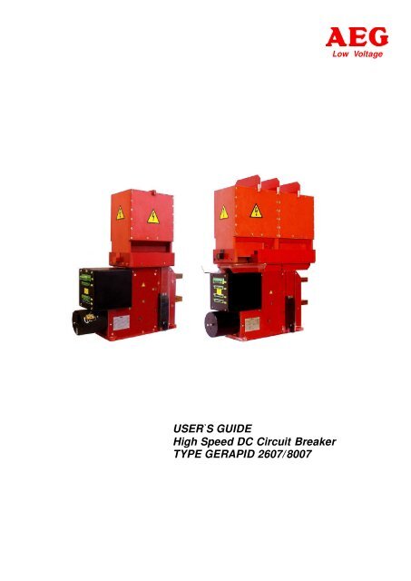
<strong>USER`S</strong> <strong>GUIDE</strong><br />
<strong>High</strong> <strong>Speed</strong> <strong>DC</strong> <strong>Circuit</strong> <strong>Breaker</strong><br />
<strong>TYPE</strong> GERAPID 2607/8007<br />
Low Voltage
User’s Guide<br />
<strong>High</strong> <strong>Speed</strong> <strong>DC</strong> <strong>Circuit</strong> <strong>Breaker</strong><br />
Type Gerapid 2607...8007<br />
Arc Chute 1X2, 1X4, 2X2, 2X3, 2X4<br />
1. General<br />
Table of Contens<br />
Page<br />
1. General 3 33<br />
1.1 General view 4<br />
1.1.1 Arc chutes 5<br />
1.2 Technical Data 6<br />
1.3 Short Description 8<br />
1.4 Structure and Components 8<br />
2. Installation and Operation 9<br />
2.1 Transportation 9<br />
2.2 Installation 9<br />
2.3 Setting the Overload Release 9<br />
2.4 Operation 10<br />
3. Inspection and Maintenance 10<br />
3.1 General 10<br />
Tables Inspection and Maintenance 11<br />
3.2 General Visual and Functional Check 12<br />
3.3 Inspecting the Arc Chute 12<br />
3.4 Checking the Condition of Contacts,<br />
Arc Probes and Protective Walls 12<br />
3.5 Checking the Chute and the Probe Screwed<br />
Connections for tightness 13<br />
3.6 Checking the Latch Mechanism and Drive 14<br />
3.7 Changing the Protective Wall 14<br />
3.8 Changing the Arc Chute 14<br />
3.9 Changing the Arc Contacts and Probes 14<br />
4. <strong>Circuit</strong> Diagrams 15<br />
5. Dimensional Drawings 28<br />
6. Eliminating Operating Troubles 39<br />
(Error Detection)<br />
7. Current measurement system type SEL 40<br />
8. Selection - Order form 41<br />
During operation, electrical equipment carries<br />
dangerous voltages. In addition, circuit breakers<br />
can emit hot, ionized gases when switching high<br />
currents, especially short circuit currents.<br />
Installing, commissioning, maintaining, changing<br />
or refitting this equipment must be carried out<br />
only by qualified and suitably trained specialist<br />
personnel and under strict observation of applicable<br />
safety regulations.<br />
During their operation, circuit breakers must be<br />
equipped with appropriately fitted covers, e.g. in<br />
suitable enclosures or panel boards. Safety distances<br />
must be observed. Certain work must only<br />
be carried out by suitably trained service personnel.<br />
Non-compliance with these warnings may result<br />
in death, and/or severe physical damage and extensive<br />
damage to equipment.<br />
Prior to carrying out maintenance, inspection or<br />
checks, the circuit breaker must be open, the both<br />
terminals must be grounded, the circuit breaker<br />
must be switched off and the control plug removed.<br />
During operation, i.e. when the circuit breaker is<br />
closed, manual activation is not permissible.<br />
Manual activation must only be used for maintenance<br />
purposes.<br />
The circuit breaker is equipped with quickly<br />
moving parts. There is a high risk of injury. Do not<br />
touch the circuit breaker while it is being switched<br />
ON or OFF.<br />
The control circuits are equipped with capacitors<br />
which may by charged with dangerous voltages.<br />
Work on this section must be carried out carefully.<br />
3
1.1. General view<br />
Arc chute<br />
Adaptor<br />
Electronic<br />
control units<br />
Arc conductor<br />
Pre-contact<br />
Main contact<br />
Control circuit<br />
terminals<br />
Main terminals<br />
Auxiliary<br />
contacts<br />
Solenoid drive<br />
Mechanical<br />
forced tripping<br />
Shunt trip<br />
No-voltage release<br />
normal operating conditions<br />
Instantaneous<br />
trip type ks<br />
quick operat ion<br />
ed-trip<br />
quick operation<br />
4
1.1.1 Arc chutes<br />
1x2 (1000V)<br />
1x4 (2000V)<br />
2x2 (2000V) 2x3 (3000V) 2x4 (4000V)
1.2 Technical Data<br />
<strong>Breaker</strong> type Gerapid 2607 Gerapid 4207<br />
Arc chute Type 1x2 1x4 2x2 2x3 2x4 1x2 1x4 2x2 2x3 2x4<br />
Rated current In/A 2.600 4.200<br />
Rated operating voltage Ue/V 1.000 2.000 2.000 3.000 3.600 1.000 2.000 2.000 3.000 3.600<br />
Rated insulation voltage Ui/V 2.000 2.000 2.000 3.000 4.000 2.000 2.000 2.000 3.000 4.000<br />
Short time current 120 min./A 3.150 5.000<br />
2 min./A 5.200 8.500<br />
20 sec./A 7.800 12.600<br />
Rated surge volt. dielectric strength UNi/kV 12 18 18 30 30 12 18 18 30 30<br />
1,2/50 µs, acc.prEN 50124-1:1997<br />
Rated short circuit breaking capacity Iss/kA 70 50 100 50 42 70 50 100 50 42<br />
acc. to EN 50123-2 INss/kA 1) 50 35 71 35 30 50 35 71 35 30<br />
Rated service short circuit breaking capacity<br />
acc. to IEC 942-2 Ics/kA 60 40 50 40 40 60 40 50 40 40<br />
Switching transient kV 2 4 4 5,6 7 2 4 4 5,6 7<br />
Mechanical endurance ops. 20.000 2) 20.000 2)<br />
Total weight approx. kg 120 120 160 160 160 120 120 160 160 160<br />
1)<br />
<strong>High</strong>er values on request (it depends on different conditions like time constant T = L/R, safety distances etc.)<br />
2)<br />
With regular maintenance 100.000 ops.<br />
Table 1a: Technical Data Gerapid 2607, 4207<br />
<strong>Breaker</strong> type Gerapid 6007 Gerapid 8007<br />
Arc chute Type 1x2 1x4 2x2 2x3 2x4 1x2 2x2 2x3<br />
Rated current In/A 6.000 8.000<br />
Rated operating voltage Ue/V 1.000 2.000 2.000 3.000 3.600 1.000 2.000 3.000<br />
Rated insulation voltage Ui/V 2.000 2.000 2.000 3.000 4.000 2.000 2.000 3.000<br />
Short time current 120 min./A 7.200 9.600<br />
2 min./A 12.000 16.000<br />
20 sec./A 18.000 24.000<br />
Rated surge volt. dielectric strength UNi/kV 12 18 18 30 30 12 18 30<br />
1,2/50 µs, acc.prEN 50124-1:1997<br />
Rated short circuit breaking capacity Iss/kA 70 50 80 50<br />
acc. to EN 50123-2 INss/kA 1) 50 35 56 35<br />
Rated service short circuit breaking capacity<br />
acc. to IEC 942-2 Ics/kA 60 40 50 40<br />
3)<br />
3)<br />
3)<br />
70<br />
50<br />
60<br />
3) 3)<br />
3) 3)<br />
3) 3)<br />
Switching transient kV 2 4 4 5,6 7 2 4 5,6<br />
Mechanical endurance ops. 20.000 2) 20.000 2)<br />
Total weight approx. kg 150 150 190 190 190 190 210 210<br />
1)<br />
<strong>High</strong>er values on request (it depends on different conditions like time constant T = L/R, safety distances etc.)<br />
2)<br />
With regular maintenance 100.000 ops.<br />
3)<br />
Test only by customer order<br />
Table 1b: Technical Data Gerapid 6007, 8007<br />
6
Auxiliary current connector 1x12-pole AC 400V, 20A<br />
3x15-pole<br />
AC 250V, 8A<br />
Activating magnet Rated voltage Uc AC 48V…230V and <strong>DC</strong> 48V…220V<br />
Operating range<br />
0.8...1.1 Uc<br />
Power consumption Gerapid 2607…6007 1750W<br />
Power consumption Gerapid 8007 2600W<br />
Minimal command signal time<br />
min.interval between two ON-operations<br />
Internal power supply Input: Voltage range <strong>DC</strong> 33...75V<br />
for Gerapid 2607…8007 Output: Voltage range <strong>DC</strong> 24V (+/-5%)<br />
or<br />
Current<br />
100ms<br />
approx. 8s without C ; approx. 14s with C<br />
6A permanent<br />
Input: Voltage range <strong>DC</strong> 50...150V<br />
Output: Voltage range <strong>DC</strong> 24V (+/-5%)<br />
Current<br />
6A permanent<br />
or<br />
Input: Voltage range AC 115...290V, <strong>DC</strong> 125...353V<br />
Output: Voltage range <strong>DC</strong> 24V (+/-5%)<br />
Current<br />
3A permanent, 5A/100ms<br />
External power supply with plug and socket unit <strong>DC</strong> 24V (+/-5%)<br />
Aux. contact HS 1…HS 10, Rated operational voltage Ue/AC 230V<br />
ks- und arc chute- indication Rated operational current Ie/AC-15 1A<br />
Rated operational current Ie/AC-12 (Ith) 10A<br />
Rated operational voltage Ue/<strong>DC</strong> 110V<br />
Rated operational current Ie/<strong>DC</strong>-13 0,5A<br />
Contact duty (min. value)<br />
<strong>DC</strong> 10V/2 mA<br />
Shunt trip (a-trip) Rated voltage Uc 24V<br />
Operating range: OFF<br />
21.6V…26.4V<br />
Power consumption<br />
approx. 100W<br />
Undervoltage trip (r-release) Rated voltage Uc 24V<br />
Operating range: OFF<br />
< 3V<br />
Operating range: ON 24V (+/-10%)<br />
Power consumption<br />
approx. 11W<br />
ed-trip Energie source: Capacity 2000µF<br />
Charging voltage<br />
300V<br />
Table 2a: Technical Data of auxiliary circuits<br />
Components<br />
Technical datas of control circuits<br />
Us / In<br />
SU-Control ON-push-button -S1 <strong>DC</strong> 24V / approx. 10mA<br />
Shunt trip (a-trip) push-button-S2 <strong>DC</strong> 24V / approx. 4,5mA<br />
Undervoltage trip (r-release) push-button-S2 ( -X2) <strong>DC</strong> 24V / approx. 10mA<br />
push-button -S2 ( -X2 :6 / :7 )<br />
<strong>DC</strong> 24V / approx. 450mA<br />
ed-trip(R = 4Ohm) push-button -S3 <strong>DC</strong> 300V / 750A / 3ms<br />
ed-trip with capacity unit Connection "Firing signal" ( -X2 :10 / :11 ) <strong>DC</strong> 6V…24V / approx.20mA<br />
Table 2b: Control <strong>Circuit</strong>s ( Directional values to rate the components )<br />
7
1.3 Short Deskription<br />
Gerapid high-speed <strong>DC</strong> circuit breakers are singlepole<br />
circuit breakers designed for use in railway<br />
propulsion-power distribution systems with operating<br />
currents up to 8000A and operating voltages up to<br />
3600V <strong>DC</strong>. They have a very high interruption capacity<br />
combined with a current limiting characteristic.<br />
Closing of the circuit breaker is performed through a<br />
high-power activation magnet. During inspections,<br />
opening and closing may be carried out by means of<br />
a hand lever, which can be mounted onto the armature<br />
of the activation magnet.<br />
Overload tripping is achieved directly via a short<br />
circuit trip or, depending on the rate of current rise,<br />
by an external current-rise release with an internal<br />
capacitor trip (ed - trip available as an accessory).<br />
Indirect remote tripping can be achieved by means<br />
of a shunt trip or an undervoltage release.<br />
The arc chute works on the basis of a highly<br />
sophisticated asbestos-free arc splitting principle.<br />
A wide variety of accessories and spares is available<br />
for maintenance, repair, or possible extension.<br />
1.4 Structure and Components<br />
Type Gerapid high speed <strong>DC</strong> circuit breakers have a<br />
compact and enclosed construction. They are IP 00<br />
protected. All parts are mounted on thick-walled,<br />
non-breakable and fireproof insulation panels,<br />
whose large covers protect the breaker’s mechanism<br />
from damage. Transparent plastic side covers<br />
are available as an accessory to protect metal connecting<br />
elements on the panel.<br />
Gerapid breakers are equipped with a two-stage<br />
contact system. The main contacts are coated with a<br />
silver composite material, the arcing contacts are<br />
made from copper and can be easily replaced. The<br />
flexible contact is linked to the connection by means<br />
of very tight braids.<br />
An attachment set is used to mount the various arc<br />
splitting systems for different operating voltages to<br />
the breakers. The arc chutes consist of a highly durable,<br />
arc-proof material, into which the arc plates<br />
have been integrated. The arc plates split the arc<br />
into partial arcs and increase the arcing voltage by<br />
multiplying the anode and cathode voltage drop.<br />
Because of their high heat capacity, the plates and<br />
arc chute walls absorb a large amount of the arc’s<br />
energy.<br />
The overload trip design uses a release magnet with<br />
twin magnets, optimizing the twin magnetic field<br />
principle. This technology ensures an equally fast<br />
tripping in both current directions. The magnetic<br />
system does not require an auxiliary voltage. The<br />
system consists of the holding circuit, the flexible<br />
armature and the tripping circuit. The holding magnet<br />
and the tripping magnet are both excited by<br />
main current.<br />
Until the static overload release’s response<br />
threshold has been reached, the flexible armature is<br />
held in position by the holding circuit’s magnetic field<br />
and the counter spring. If the main current exceeds<br />
the set static response threshold, the tripping circuit’s<br />
power takes over and pulls the flexible armature<br />
down suddenly. During this operation, the armature<br />
trips the release lever. The main latch and<br />
contacts are opened immediately. The response<br />
threshold can be easily adjusted by turning the adjustment<br />
nut with a SW6 hexagon wrench. In combination<br />
with the transparent side cover accessory, a<br />
fixed mounted insulated knob is available (accessory).<br />
To detect high short circuit currents early and to record<br />
leakage currents in long peripheral sections (for<br />
railway equipment), whose final values are lower<br />
than the highest operating currents, protective relays<br />
for monitoring a current increase should be installed.<br />
If a fault occurs, a release signal can be passed on<br />
to the capacitor release, which causes the breaker<br />
to open rapidly (opening delay
The activation magnet is mounted at the front of the<br />
breaker and is equipped with a grounded casing.<br />
The drive includes a self-interrupt control circuit (SUcontrol).<br />
This circuit enables a short activation with a<br />
minimum command duration of approximately<br />
300ms, causes the voltage applied to the magnet to<br />
be switched off after approximately 400ms and prevents,<br />
during continuous operation, repeated activation<br />
(anti-pumping) due to an existing short circuit. In<br />
addition, the switch-in mechanism is electrically<br />
blocked for approximately 10s after activation. This<br />
prevents premature activation following a short circuit.<br />
The breaker is equipped with up to ten isolated<br />
form C auxiliary contacts (1 NO/NC each). The<br />
auxiliary contacts are activated by the movable main<br />
contact. They are wired to 15-pin control plugs. As<br />
an accessory the circuit breaker can be equipped<br />
with auxiliary switches for indication of short circuit<br />
tripping and for the presence of the arc chute.<br />
2. Installation and Operation<br />
2.1 Transportation<br />
The circuit breaker must always be transported to<br />
the installation site properly and fully packed. The<br />
packaging protects the device against damage and<br />
dust; it should only be removed prior to installation.<br />
If the packaging is damaged, the breaker and the<br />
arc chute must be inspected for damage. Ensure<br />
that all packaging materials have been carefully removed<br />
prior to breaker installation.<br />
2.2 Installation<br />
The breakers, as delivered, are IP00 protected.<br />
They must be installed in a dry, preferably dust-free<br />
room. They must not be subjected to strong vibrations.<br />
The lower and upper connections must be<br />
connected directly to the main cables and busbars.<br />
The breaker must only be used in an upright<br />
operation position with the arc chute in place<br />
and fully secured. After installation, both the arc<br />
chute and special threaded joints must be checked<br />
for tightness.<br />
The safety distances as shown in the dimensional<br />
drawings must be maintained to grounded or insulated<br />
parts. Suitable measures must be taken to<br />
protect personnel from arcs.<br />
Strong, external magnetic fields, caused by<br />
improperly located supply conductors or stray fields<br />
from other devices, can lead to a shift of the trip setting<br />
thresholds. This may result in premature tripping,<br />
or no tripping at al, during low-level short circuit<br />
current events. This has to be accounted for<br />
when installing and operating the device with<br />
shielding added if appropriate.<br />
The control wires must be connected as shown in<br />
the schematic circuit diagram [Fig.8].<br />
The protective grounding wire must be connected at<br />
the marked contact.<br />
2.3 Setting the Overload Release<br />
The adjustment of the static overload release [Fig.1]<br />
within a specific adjustment range is made by turning<br />
the regulating screw. This procedure requires an<br />
SW6 hexagon wrench. The adjustment must only be<br />
carried out after the breaker has been disconnected<br />
from the main circuit and has been grounded. Turning<br />
the adjustment screw clockwise decreased the<br />
trip threshold, turning the screw counter-clockwise<br />
increased the tripping threshold.<br />
Adjustment is performed by aligning both the arrow<br />
and the marking line to one line.<br />
9
2.4 Operation<br />
3. Inspection and Maintenance<br />
Maximum operating voltage and current ratings are<br />
as shown on the breaker nameplate.<br />
During continuous operation, it must be loaded with<br />
its rated operating current at maximum. Load currents<br />
in excess of breaker nameplate rating are allowable<br />
for brief periods. Refer to the short time currents<br />
listed in Table 1a/1b. Do not exceed the rated<br />
operating voltage shown on the breaker nameplate.<br />
The drive and auxiliary trips function within the<br />
specified control voltage range. The auxiliary trips<br />
must be loaded with the values listed in Table 2a at<br />
maximum.<br />
Prior to carrying out maintenance, inspection or<br />
checks on the circuit breaker, the breaker must<br />
be open, the connections on both sides must be<br />
grounded, the circuit breaker must be switched<br />
off and the control plugs removed.<br />
Non-compliance with these warnings can result<br />
in death, severe physical damage and extensive<br />
damage to equipment.<br />
Metric tools are needed for all screws.<br />
3.1 General<br />
Regular inspection and maintenance must be carried<br />
out to ensure the proper functioning of the<br />
breaker and in order to achieve a long working life.<br />
The intervals at which inspections must be carried<br />
out may be determined by evaluating the breaker’s<br />
duty cycle. Table 3a provides an overview of checks<br />
to be carried out and lists the appropriate inspection<br />
intervals. Table 3b provides indicators for maintenance<br />
work. In order to check the latch mechanism,<br />
the breaker can be opened and closed with a hand<br />
lever. Fig. 2 shows the correct use of the lever.<br />
Fig.1 Setting the overload release<br />
Fig. 2 Manual ON/OFF.<br />
10
Type of inspection Intervals of inspection Work to be carried out<br />
General visual and functional<br />
check<br />
Checks:<br />
-Contacts<br />
-Arc probes<br />
-Protective walls<br />
-Arc chute (LBK)<br />
Check breaker and tripping<br />
mechanism. To be carried out<br />
by trained specialist.<br />
Check arc probes and arc<br />
chute screw connections<br />
Recommended: every 6 months<br />
At least once a year<br />
After high short circuit openings<br />
(>25kA)<br />
or frequent operations with overloadand/or<br />
rated current<br />
At least once a year<br />
After 5000 mech. operations<br />
At least once every 4 years<br />
After each job carried out in the<br />
contacts probe or arc chute<br />
At least once every 6 months<br />
Remove dirt, check drive and<br />
trips for correct operations<br />
Check for wear and deposits<br />
Check proper operation,<br />
setting values and flexible braid<br />
Check for tight fitting<br />
Table 3a: Inspections required<br />
Work to be carried out<br />
required<br />
Changing arc-chute (LBK)<br />
As required by the results of the inspection<br />
Adjustment of latch mechanism<br />
Exchange parts<br />
Replaces of:<br />
-Pre-arcing contacts (wear contacts)<br />
-Arc probes<br />
-Protective walls<br />
As required by the results of the inspection,<br />
or to be done latest after<br />
100 overload operations or<br />
300 loadbreak operations at rated current<br />
Table 3b: Maintenance required<br />
11
3.2 General Visual and Functional Check<br />
Disconnect breaker from main circuit, make sure it is<br />
not live, earth on both sides and pull out control<br />
plugs.<br />
Check breaker for presence of dirt, and, if applicable,<br />
remove all dirt with a dry cloth.<br />
Switch the breaker ON and OFF several times. The<br />
contacts must close after the ON command, the<br />
contacts must open following the OFF command via<br />
the shunt trip and the undervoltage release.<br />
The breaker mechanism must not appear sluggish<br />
nor must ON/OFF be unduly delayed. No particularly<br />
high signs of abrasion (rough chips) should be seen<br />
anywhere.<br />
3.3 Inspecting the Arc Chute<br />
Fig.3 Inspecting the Arc Chute<br />
Disconnect breaker from main circuit, make sure it is<br />
not live, ground on both sides and pull out control<br />
plug.<br />
[Fig.6] Loosen the clamping screws 5 and 8 with an<br />
SW 5 hexagon wrench and lift the arch chute 1 off<br />
the breaker.<br />
[Fig.3] Check the chute’s interior, as far as possible,<br />
for deposits and check the general condition of the<br />
insulation material and the arc horns for wear.<br />
During this inspection check whether there are many<br />
copper pearls on the chute’s plates 1(that could partially<br />
link the plates), whether the arc horns’ cross<br />
section 2 is heavily reduced, whether the splitting<br />
plates 3 are heavily burned and whether the chute’s<br />
internal insulation is heavily damaged.<br />
[Fig.6] Replace arc chute 1 on the breaker and secure<br />
with bolts 5 and 8 and toothed disks 6 and 9<br />
using a torque of 10 Nm.<br />
3.4 Checking the Condition of Contacts, Arc<br />
Probes and Protective Walls<br />
Disconnect breaker from main circuit, make sure it is<br />
not live, ground on both sides and pull out control<br />
plugs<br />
[Fig.6] Loosen the clamping screws 5 and 8 with an<br />
SW 5 hexagon wrench and lift the arc chute 1 off the<br />
breaker.<br />
12
[Fig.4] The arc contacts should not be burned below<br />
1/3 of the total cross section in any place. Pay<br />
particular attention to the area around probe bend<br />
3 and pre-arcing contact 2. Wear on pre-arcing<br />
contact 1 should amount to no more than 2mm; the<br />
limiting value is 3mm! If it is burned down more, it<br />
must be replaced. The main contacts 4 should not<br />
show any particular signs of material erosion,<br />
since, in the case of ordinary short circuits or<br />
overload and operating current deactivation, the<br />
arc is ignited between the pre-arcing contacts.<br />
Ignition can take place on the main contacts only<br />
with excessively worn and old pre-arcing contacts<br />
or very high short circuit currents. The wear should<br />
not exceed an area of 1mm. The material erosion<br />
rate on the protective walls 5 must not exceed<br />
1mm in any place.<br />
3.5 Checking the chute and the probe screwed<br />
connections for tightness<br />
Disconnect breaker from main circuit, make sure it<br />
is not live, ground on both sides and pull out control<br />
plugs.<br />
[Fig.5] Tighten arc chute and arc probe screw<br />
connections with a torque of 10 Nm. Ensure that<br />
the screws are in good condition, that there is no<br />
damage to the thread or the tool insertion point and<br />
that the surface is free from rust. If this is not the<br />
case, they must be replaced.<br />
Every screw connection must be secured by<br />
means of a safety element-lock washer DIN 6796.<br />
This check must be carried out prior to commissioning<br />
and after every maintenance<br />
[Fig.6] Replace arc chute 1 onto the breaker and<br />
secure with bolts 5 and 8 and toothed disks 6 and<br />
9 using a torque of 10 Nm.<br />
Check both the arc chute and the arc probe<br />
screwed connections after installation.<br />
Hexagon wrench SW 5<br />
Fig.4 Checking the Contacts and the<br />
Protective Walls<br />
Fig.5 Checking Chute and Probe Screwed<br />
Connections<br />
13
3.6 Checking the Latch Mechanism and Drive<br />
A thorough check of the latch mechanism and the<br />
current path should only be carried out by service<br />
engineers or technicians trained and qualified by<br />
AEG Industrial Systems<br />
3.7 Changing the Protective Wall<br />
Disconnect breaker from main circuit, make sure it<br />
is not live, ground on both sides and pull out control<br />
plug.<br />
[Fig.6]Loosen the clamping screws 5 and 8 with an<br />
SW5 hexagon wrench and lift the arc chute 1 off<br />
the breaker.<br />
[Fig.7] Carefully pull out the old protective walls 5<br />
and insert new ones.<br />
Fig.6 Installing the Arc Chute<br />
[Fig.6] Replace arc chute 1 onto the breaker and<br />
secure with bolts 5 and 8 and toothed disks 6 and<br />
9 using a torque of 10 Nm.<br />
Check both the chute and the probe screwed connections<br />
after installation.<br />
3.8 Changing the Arc Chute<br />
Disconnect breaker from main circuit, make sure it<br />
is not live, ground on both sides and pull out control<br />
plug.<br />
[Fig.6] Loosen the clamping screws 5 and 8 with<br />
an SW5 hexagon wrench and lift the arc chute 1 off<br />
the breaker.<br />
Put the new arc chute 1 onto the breaker and secure<br />
with bolts 5 and 8 and toothed disks 6 and 9<br />
using a torque of 10 Nm.<br />
Check both the arc chute and the arc probe<br />
screwed connections after installation.<br />
3.9 Changing the Arc Contacts and Arc Probes<br />
See technical information “<strong>High</strong> <strong>Speed</strong> <strong>DC</strong> <strong>Circuit</strong><br />
<strong>Breaker</strong> Type Gerapid, Hints + Instructions”.<br />
Fig.7 Changing the Protective Wall<br />
14
4. <strong>Circuit</strong> Diagrams<br />
Activating magnet<br />
(Solenoid drive)<br />
a-trip or r-release<br />
ed-trip<br />
ks-trip<br />
HS 1...HS 10<br />
ks-indication<br />
arc chute-indication<br />
Description<br />
Designation<br />
X2<br />
1.Connector: Auxiliary- and control circuits<br />
X3<br />
2.Connector: Auxiliary- and control circuits<br />
X4<br />
3.Connector: Auxiliary contacts HS1...HS5<br />
X5<br />
4.Connector: Auxiliary contacts HS6...HS10<br />
X6<br />
5.Connector: Current measure system SEL<br />
X10<br />
Control board: Power supply unit<br />
X11<br />
Control board: Voltage supply <strong>DC</strong> 24V external<br />
X12<br />
Control board: Self interrupt control (SU)<br />
X13<br />
Control board: Shunt trip (a-trip)<br />
X14, X15 Control board: Undervoltage trip (r-release) (X15: r-release mod.)<br />
X16<br />
Control board: ed charge- and trip component<br />
X17<br />
Control board: Current measure system SEL<br />
Fig. 8 Connecting plug allocation<br />
15
Basic Connections Definitions<br />
The power circuits are not shown in the wiring diagrams<br />
due to clarity. The control circuit is presented<br />
as a typical circuit diagram and is a combination<br />
of numbered basic diagrams for drives,<br />
trips and indicators. The number of the complete<br />
diagram can be derived by using the key numbers<br />
of the basic plan.<br />
Key position 1 / 2 3 4 5 6 7 8<br />
Type<br />
Aux. voltage<br />
Tripping coil<br />
Drive<br />
Tripping dev.<br />
Indicat. switch<br />
Aux. contacts<br />
Current-meas.<br />
system<br />
Key position<br />
Key Key Designation<br />
position number<br />
Type<br />
1 36 Gerapid<br />
Auxiliary voltage<br />
2 1 AC/<strong>DC</strong> Converter<br />
2 <strong>DC</strong> 24V external supply<br />
Tripping coil<br />
3 0 Without ed-trip coil<br />
1 With ed-trip coil<br />
2 With ed-trip coil and<br />
internal capacitor unit<br />
Drive<br />
4 20 Solenoid drive with<br />
Self cut-off control<br />
Tripping device<br />
5 00 Without trip<br />
10 With shunt trip<br />
20 With undervoltage trip<br />
Indication device<br />
6 00 Without indication<br />
01 ks-indication<br />
02 Arc chute indication<br />
03 ks+arc chute indication<br />
Auxiliary contacts<br />
7 1 3 auxiliary switches<br />
2 5 auxiliary switches<br />
3 10 auxiliary switches<br />
Current-measurement system<br />
8 S With SEL<br />
Example: complete diagram No.<br />
Key position 36 / 1 1 20 10 01 2 S<br />
Gerapid<br />
Power supply<br />
ed-trip coil<br />
Drive+SU<br />
Shunt trip<br />
ks-Indication<br />
5 Aux.contacts<br />
SEL<br />
Indication of components<br />
Q1<br />
S1<br />
S2<br />
<strong>Circuit</strong> breaker<br />
Push button „ON“<br />
Push button „OFF“"<br />
Cut off control unit:<br />
K1 Closing relay<br />
K2 Closing block relay<br />
Shunt trip, undervoltage trip:<br />
K1 Closing STOP relay<br />
HS11 Auxiliary contact<br />
ed-trip with internal capacitor unit:<br />
K1 Voltage monitoring relay<br />
16
3)S3<br />
3)S3<br />
2) S2<br />
2)S2<br />
1)S2<br />
1) S2<br />
S1<br />
S1<br />
PE<br />
Power supply<br />
S2<br />
Q1:X2<br />
12<br />
11<br />
10<br />
9<br />
8<br />
7<br />
6<br />
5<br />
4<br />
3<br />
2<br />
1<br />
Power supply<br />
Power supply<br />
Q1:X3<br />
15<br />
14<br />
13<br />
12<br />
11<br />
10<br />
9<br />
8<br />
7<br />
6<br />
5<br />
4<br />
3<br />
2<br />
1<br />
5)<br />
5)<br />
4)<br />
4)<br />
3)<br />
3)<br />
Q1:X4<br />
15<br />
14<br />
13<br />
12<br />
11<br />
10<br />
9<br />
8<br />
7<br />
6<br />
5<br />
4<br />
3<br />
2<br />
1<br />
Q1:X5<br />
15<br />
14<br />
13<br />
12<br />
11<br />
10<br />
9<br />
8<br />
7<br />
6<br />
5<br />
4<br />
3<br />
2<br />
1<br />
Q1:X6<br />
15<br />
14<br />
13<br />
12<br />
11<br />
6) S4 10<br />
6) S4 9<br />
8<br />
7<br />
-<br />
6<br />
6)<br />
5<br />
+ 6)<br />
-<br />
4<br />
6)<br />
+<br />
3<br />
6)<br />
-<br />
2<br />
6)<br />
+<br />
1<br />
6)<br />
+/- 10V<br />
+/- 20mA<br />
4...20mA<br />
Position of auxiliary switches is shown in the Off position of maincontacts<br />
1) with shunt trip<br />
2) with undervoltage trip<br />
3) with ed trip<br />
4) with ks tripping indicator switch<br />
5) with arc chute mounted indicator switch<br />
6) with current measurement unit (polarity of the output signal<br />
shown by current flow from top to bottom connection of the<br />
breaker)<br />
Fig. 9 Connecting plug termination (Indicating switches, 3 auxiliary switches)<br />
17
Q1:X3<br />
3) S3<br />
3) S3 2)S2<br />
15<br />
14<br />
Q1:X2<br />
13<br />
12<br />
12<br />
11<br />
11<br />
10<br />
10<br />
9<br />
9<br />
2) S2 8<br />
8<br />
1) S2 7<br />
7<br />
1)S2 6<br />
6<br />
S1<br />
Power supply<br />
5<br />
5<br />
S1<br />
Power supply<br />
4<br />
4<br />
PE 3<br />
3<br />
Power Supply<br />
2<br />
2<br />
S2 1<br />
1<br />
5)<br />
5)<br />
4)<br />
4)<br />
3)<br />
3)<br />
Q1:X4<br />
15<br />
14<br />
13<br />
12<br />
11<br />
10<br />
9<br />
8<br />
7<br />
6<br />
5<br />
4<br />
3<br />
2<br />
1<br />
Q1:X5<br />
15<br />
14<br />
13<br />
12<br />
11<br />
10<br />
9<br />
8<br />
7<br />
6<br />
5<br />
4<br />
3<br />
2<br />
1<br />
6)S4<br />
6)S4<br />
Q1:X6<br />
15<br />
14<br />
13<br />
12<br />
11<br />
10<br />
9<br />
8<br />
7<br />
6<br />
5<br />
4<br />
3<br />
2<br />
1<br />
-<br />
6)<br />
+ 6)<br />
-<br />
6)<br />
+<br />
6)<br />
-<br />
6)<br />
+ 6)<br />
+/- 10V<br />
+/- 20mA<br />
4...20mA<br />
Position of auxiliary switches is shown in the Off position of maincontacts<br />
1) with shunt trip<br />
2) with undervoltage trip<br />
3) with ed trip<br />
4) with ks tripping indicator switch<br />
5) with arc chute mounted indicator switch<br />
6) with current measurement unit (polarity of the output signal<br />
shown by current flow from top to bottom connection of the<br />
breaker)<br />
Fig. 10 Connecting plug termination (Indicating switches, 5 auxiliary switches)<br />
18
3)S3<br />
3)S3<br />
2) S2<br />
2)S2<br />
1)S2<br />
1) S2<br />
S1<br />
S1<br />
PE<br />
Power supply<br />
S2<br />
Q1:X2<br />
12<br />
11<br />
10<br />
9<br />
8<br />
7<br />
6<br />
5<br />
4<br />
3<br />
2<br />
1<br />
Power supply<br />
Power supply<br />
Q1:X3<br />
15<br />
14<br />
13<br />
12<br />
11<br />
10<br />
9<br />
8<br />
7<br />
6<br />
5<br />
4<br />
3<br />
2<br />
1<br />
5)<br />
5)<br />
4)<br />
4)<br />
3)<br />
3)<br />
Q1:X4<br />
15<br />
14<br />
13<br />
12<br />
11<br />
10<br />
9<br />
8<br />
7<br />
6<br />
5<br />
4<br />
3<br />
2<br />
1<br />
Q1:X5<br />
15<br />
14<br />
13<br />
12<br />
11<br />
10<br />
9<br />
8<br />
7<br />
6<br />
5<br />
4<br />
3<br />
2<br />
1<br />
Q1:X6<br />
15<br />
14<br />
13<br />
12<br />
11<br />
6) S4 10<br />
6) S4 9<br />
8<br />
7<br />
-<br />
6<br />
6)<br />
5<br />
+ 6)<br />
-<br />
4<br />
6)<br />
+<br />
3<br />
6)<br />
-<br />
2<br />
6)<br />
+<br />
1<br />
6)<br />
+/- 10V<br />
+/- 20mA<br />
4...20mA<br />
Position of auxiliary switches is shown in the off position of maincontacts<br />
1) with shunt trip<br />
2) with undervoltage trip<br />
3) with ed trip<br />
4) with ks tripping indicator switch<br />
5) with arc camber mounted indicator switch<br />
6) with current measurement unit (polarity of the output signal<br />
shown by current flow from top to bottom connection of the<br />
breaker)<br />
Fig. 11 Connecting plug termination (Indicating switches, 10 auxiliary switches)<br />
19
-Q1 Drive<br />
+ / ~<br />
-X12<br />
2<br />
1<br />
-S3<br />
3<br />
-X2<br />
:1<br />
~<br />
Power supply<br />
of the drive<br />
-<br />
+<br />
4<br />
~<br />
-X2<br />
:2<br />
Power <strong>Circuit</strong><br />
-S1<br />
ON Command<br />
-X2<br />
-X2<br />
-X10, 11<br />
:5<br />
:4<br />
:9<br />
9<br />
8<br />
10<br />
Closing Control<br />
Closing Block Release<br />
-X10, 11<br />
:6<br />
7<br />
ON Signal circuit<br />
5 6<br />
Closing<br />
Stop Signal<br />
N / ~<br />
36/ . . XX .. .. .<br />
Key No. 20<br />
Fig. 12 Activating magnet with SU control-circuit<br />
20
Closing Stop Signal<br />
X13<br />
5 6<br />
-K1<br />
:6<br />
4<br />
7<br />
-X10, 11<br />
:7<br />
-<br />
-S2<br />
24 V<br />
:7<br />
3<br />
A1<br />
-K1<br />
A2<br />
8<br />
-X10, 11<br />
:9<br />
+<br />
2<br />
3<br />
9<br />
-HS11<br />
C1<br />
4<br />
1<br />
10<br />
C2<br />
36/ . . .. XX .. .<br />
Key No. 00 without auxiliary trip<br />
Key No. 10 with shunt trip<br />
Fig. 13 Shunt trip<br />
21
-S2<br />
-X2 -X2<br />
:7 :6<br />
X13<br />
3 4<br />
5<br />
-K2<br />
A1<br />
-K1<br />
Closing Stop Signal<br />
A2<br />
6<br />
-<br />
7<br />
2<br />
-X2<br />
24 V<br />
+<br />
8<br />
-S2<br />
A1<br />
A2<br />
-K1 -K2<br />
1<br />
-X2<br />
-D1<br />
9 10<br />
U<<br />
36/ . . .. XX .. .<br />
Key No. 20 with undervoltage<br />
trip<br />
Fig. 14 Undervoltage trip<br />
22
Voltage converter<br />
33..353V <strong>DC</strong> 115..290V AC<br />
~ / +<br />
Voltage converter<br />
external 24V <strong>DC</strong> +/-5%<br />
+ 24 V<br />
-X10<br />
-X3<br />
Input 33....75V <strong>DC</strong> (R3)<br />
50..150V <strong>DC</strong> (R4)<br />
125..353V <strong>DC</strong> (R5)<br />
115..290V AC (R5)<br />
Output 24V <strong>DC</strong> +/- 5%<br />
4<br />
1<br />
3<br />
10<br />
9<br />
+24V<br />
8<br />
Closing Stop<br />
7<br />
6 -24V<br />
-X3<br />
4<br />
3<br />
1<br />
-X11<br />
10<br />
9<br />
8<br />
7<br />
6<br />
Closing<br />
Stop<br />
-X3<br />
5<br />
-X3<br />
5<br />
N / -<br />
- 24 V<br />
36/ X . .. .. .. .<br />
Key No. 1 Voltage converter 33..75V <strong>DC</strong>; 50..150V <strong>DC</strong>; 125..353V <strong>DC</strong>; 115..290V AC<br />
Key No. 2 Voltage converter external 24V +/- 5%<br />
Fig. 15 Power supply unit internal ( AC/<strong>DC</strong> ) and external ( <strong>DC</strong> 24V +/- 5% )<br />
23
-X16<br />
-X10, 11<br />
:8<br />
+<br />
1<br />
Power supply<br />
24V <strong>DC</strong><br />
Insulating Transformer<br />
-X10, 11<br />
-<br />
:6<br />
2<br />
Pulse <strong>Circuit</strong><br />
Charging control<br />
-X3<br />
Signal C<br />
charged<br />
-X3<br />
:6<br />
:7<br />
9<br />
10<br />
5<br />
Voltage Control<br />
Closing<br />
Stop Signal<br />
6<br />
Contactors<br />
+<br />
-X2:10<br />
Firing Signal<br />
6..24V<br />
-<br />
-X2:11<br />
3<br />
4<br />
Firing circuit<br />
Firing signal<br />
transforming<br />
and control<br />
11<br />
Q1 ed<br />
12<br />
Capacity and firing thyristor<br />
36/ . X .. .. .. .<br />
Key No. 2 with ed-trip and capacity unit<br />
Fig. 16 ed-trip (electrodynamic-trip) with capacitor unit<br />
24
-S3<br />
Impulsecapacity<br />
300V 2000µF<br />
-X2<br />
:10<br />
-Q1<br />
ed<br />
-X2<br />
:11<br />
36/ . X .. .. .. ..<br />
Key No. 0 without ed trip<br />
Key No. 1 with simple ed trip<br />
Fig. 17 ed-trip (electrodynamic-trip)<br />
25
-X3<br />
:8<br />
-X3<br />
:12<br />
-X3<br />
:9<br />
-X3<br />
:13<br />
36/ . . .. .. xx . . 36/ . . .. .. xx . .<br />
Key No. 00 without indication<br />
Key No. 01 with ks-indication<br />
Key No. 02 with arc chute-indication<br />
-X3<br />
:8<br />
-X3<br />
:12<br />
-X3<br />
:9<br />
-X3<br />
:13<br />
36/ . . .. .. xx . .<br />
Key No. 03 with ks- und arc chute- indication<br />
Fig. 18 ks- und arc chute- indication<br />
26
-X17<br />
4..20mA Output<br />
1) -X6<br />
-X6<br />
11<br />
12<br />
4....20 mA<br />
1<br />
23<br />
4<br />
S I<br />
1. Sensor<br />
+/-20mA Output<br />
2) -X6<br />
-X6<br />
13<br />
14<br />
+/- 20 mA<br />
Signalconditioning<br />
5<br />
6<br />
7<br />
8<br />
S II<br />
2. Sensor<br />
+/-10V Output<br />
3) -X6<br />
-X6<br />
15<br />
16<br />
+/- 10 V<br />
Voltage<br />
Converter<br />
17 18 9 10<br />
19<br />
Power<br />
supply 24V<br />
-X10, 11<br />
-X12<br />
-X6 -X6<br />
-X13 -X10 -X2<br />
Power<br />
Supply 24V<br />
1) max. 500 W<br />
2) max. 500 W<br />
3) min. 300 kW<br />
36/ . . .. .. .. . X<br />
Key No. „S“ with SEL<br />
Fig. 19 Current measurement system type SEL 06-1...12-4<br />
27
5. Dimensional drawings<br />
Warnings<br />
During operation all metallic parts of the breaker except housing and driving magnet may<br />
carry dangerous voltages. Insulation covers available as accessories.<br />
For installation of the breaker into cubicles top and side openings are to provide in order to<br />
reduce internal pressure rise in case of clearing short circuit.<br />
All openings respectively free areas on the top of the cubical shall be not less than 50%.<br />
28
Type Arc chute Main- additional Deflector Safety distances / Insulated plates Safety distances / Earthed plates<br />
Gerapid Connection isolation<br />
action E A B C D A B C D<br />
2607 / 4207 1x2 all 10 700 150 150 120 1000 300 300 300<br />
1x3 all 1) 1) 1) 1) 1) - - - -<br />
1x4 all 150 700 150 150 120 1350 450 450 200<br />
2x2 all 80 1000 300 300 300 1350 450 450 300<br />
2x3 all 80 1000 180 180 180 - - - -<br />
2x4 W / W Plate 150 1000 180 180 180 - - - -<br />
2x4 W / W Sidewalls 150 1000 180 180 180 - - - -<br />
2x4 SEL / W Pan 150 1000 180 180 180 - - - -<br />
6007 1x2 S / S Heat sink 10 1000 300 300 180 - - - -<br />
1x3 1) 1) 1) 1) 1) 1) 1) - - - -<br />
1x4 S / S Heat sink 150 1000 300 300 180 - - - -<br />
2x2 S / S Heat sink 80 1000 180 180 180 - - - -<br />
2x3 S / S Heat sink 80 1000 180 180 180 - - - -<br />
2x4 1) 1) 1) 1) 1) 1) 1) - - - -<br />
8007 1x2 S / S Heat sink 10 1000 300 300 180 - - - -<br />
1x3 1) 1) 1) 1) 1) 1) 1) - - - -<br />
1x4 1) 1) 1) 1) 1) 1) 1) - - - -<br />
2) 2x2 S / S Heat sink 80 1000 180 180 180 - - - -<br />
2) 2x3 S / S Heat sink 80 1000 180 180 300 - - - -<br />
2x4 1) 1) 1) 1) 1) 1) 1) - - - -<br />
1) will be checked by customers order<br />
2) acc. IEC 947-2 / ks-setting
Fig. 20 Gerapid 2607- 6007, arc chute 1X (Dimensions in mm)<br />
Pay attention to warnings page 26! Legend and safety distances see page 27<br />
30
Fig. 21 Gerapid 2607- 6007, arc chute 2X (Dimensions in mm)<br />
Pay attention to warnings page 26! Legend and safety distances see page 27<br />
31
Fig. 22 Gerapid 8007, arc chute 1X (Dimensions in mm)<br />
Pay attention to warnings page 26! Legend and safety distances see page 27<br />
32
Fig. 23 Gerapid 8007, arc chute 2X (Dimensions in mm)<br />
Pay attention to warnings page 26! Legend and safety distances see page 27<br />
33
Fig. 24 Gerapid 2607 / 4207 connections horizontal (Dimensions in mm)<br />
It’s able to combine connections horizontal and vertical, dimensions are corresponding.<br />
34
Fig. 25 Gerapid 2607 / 4207 connections vertical (Dimensions in mm)<br />
It’s able to combine connections horizontal and vertical, dimensions are corresponding.<br />
35
Fig. 26 Gerapid 6007, connections vertical only (Dimensions in mm)<br />
36
Fig. 27 Gerapid 8007, connections vertical only (Dimensions in mm)<br />
37
Forced tripping device<br />
Fig. 28 Bottom view<br />
Fig. 29 Length of stroke<br />
38
6. Eliminating Operating Troubles (Error detection)<br />
SWITCHING ON NOT POSSIBLE<br />
„Activating magnet doesn't work electrical but (after making sure it's not alive!) works mechanical<br />
with the hand lever."<br />
• Control voltage Us not available or to low?<br />
Check, if voltage delivered by the power supply is not available or to low<br />
(measure points :4/:5)<br />
• Voltage loss to large at the coil of the activating magnet?<br />
Measure or calculate control voltage Uc of the magnet.<br />
• Control cable interrupted or not correct connected ?<br />
• If control voltage o.k. change circuit board.<br />
• Note the polarity of the power supply.<br />
Check measure points :1/:2 at plug X2 and measure points :4/:5 at plug X3.<br />
• Check if error in customized auxiliary control circuit.<br />
• Activating magnet faulty? (Change it).<br />
„Activating magnet works electrical“<br />
• If available, check r-release<br />
- Control voltage available?<br />
- Feeding and connection o.k.?<br />
- r-release coil faulty?<br />
• Check, if positive tripping is wrong adjusted.<br />
• Faulty mechanic? (Call service department)<br />
Switching off the breaker not possible<br />
„a-release don't release“<br />
• Control voltage available ?<br />
• Control plug o.k.?<br />
• Control cables o.k.?<br />
• a-release faulty? (change it)<br />
• Auxiliary switch HS 11 wrong adjusted?<br />
• Faulty mechanic ? (call service department)<br />
„r-release don't release“<br />
• Faulty mechanic ? (call service department)<br />
„ed-trip unit don't release“<br />
• Capacitors circuitboard faulty? (change it)<br />
• Interface of line measuring device faulty?<br />
Faulty circuitboards<br />
• Change the complete circuit board<br />
39
7. Gerapid 2607/4207 - Current measurement system type SEL<br />
SEL–TheintegratedSolution<br />
Themainpurposeofthehighspeed<strong>DC</strong>circuitbreaker<br />
typeGerapidistheinterruptionofservicecurrentsand<br />
protection of mains against short circuit.. Current<br />
measuringrequirestheinstallationofexternaldevices<br />
e.g. shunt –buffer amplifier which needs mounting<br />
timeaswellasadditionalspace.<br />
Now the Gerapid offers the new feature – current<br />
measuring with the sophisticated current<br />
measurementsystem TypeSEL06-1....12-4<br />
Theadvantagescomparedwith theconventional<br />
systemsare<br />
thetransducerisintegratedin theGerapid<br />
noadditionalassemblywork<br />
noadditionalmountingspace<br />
low noisemeasur ing without anyfiltering<br />
ranges 6kAand 12kA<br />
3differentinterfaces<br />
applicableupto4000V<strong>DC</strong><br />
!<br />
!<br />
!<br />
!<br />
!<br />
Theoscillogramsbelowshowthehighaccuracyofthe<br />
current measurement system type SEL in comparison<br />
with the conventional method using ashunt -buffer<br />
amplifier.<br />
MeasurementwithShunt-BufferAmplifier<br />
1200<br />
1000<br />
800<br />
600<br />
400<br />
200<br />
0<br />
-200<br />
0 100 200 300 400 500 600<br />
Time t [ms]<br />
Measurementwith CurrentMeasurement<br />
SystemType SEL<br />
1200<br />
1000<br />
800<br />
600<br />
400<br />
200<br />
0<br />
-200<br />
0 100 200 300 400 500 600<br />
Time t [ms]<br />
Structure<br />
ThecurrentmeasurementsystemTypeSEL06-1...12-4<br />
consists of the components sensor and signal<br />
processingunit.<br />
Hall probes record the the magnetic field surrounding<br />
the current. The special design and the high<br />
performance shielding minimise the influence of<br />
interference.<strong>High</strong>build-upofcurrentisrecordedinreal<br />
time.<br />
Thesensorisintegratedintoaspeciallydesignedupper<br />
terminal of the Gerapid and connected by ascreened<br />
cablewiththesignalprocessingunit.<br />
This signal processing unit transfers the input signal<br />
whichisproportionaltothecurrentsignalintodifferent<br />
outputsignals.<br />
Theusercanselectbetweentheinterfaces<br />
!<br />
!<br />
!<br />
Technical Data<br />
Type SEL 06-1 06-2 06-4 12-1 12-2 12-4<br />
Input -6 to 6 kA -12 to 12kA<br />
U Ne[V] 1000 2000 4000 1000 2000 4000<br />
Relating to rated current<br />
I Ne<br />
4...20mA,<br />
+/-20mA,<br />
+/-10V<br />
All interfaces are potential free. Phase failures are<br />
automaticallydetectedundindicatedbyazero-signal<br />
onthe4...20mAoutput.<br />
Output<br />
4...20mA<br />
-20...20mA<br />
-10...10V<br />
U Ni[kV] 12 18 40 12 18 40<br />
Design and specifications aresubject tochangewithoutnotice<br />
40
8. Selection - Order form<br />
41
APPARECCHIATURE<br />
ELETTRICHE<br />
INDUSTRIALI<br />
VII a Strada, 7 - Z. I. Nord<br />
35129 Padova<br />
Tel. +39 0498075544 - Fax +39 0498077695<br />
E-mail info@aegelettra.it<br />
Web www.aegelettra.it<br />
srl<br />
C_Gerapid04R1 - Fotocomposizione Elettra