Prediction of batch heat transfer coefficients for pseudoplastic fluids ...
Prediction of batch heat transfer coefficients for pseudoplastic fluids ... Prediction of batch heat transfer coefficients for pseudoplastic fluids ...
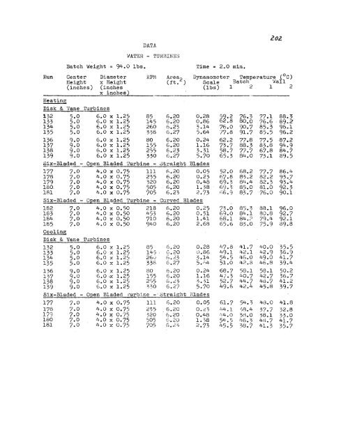
DATA 20l. WATER - TUHBINSS Batch Weight = 94.0 Ibs. Time = 2.0 min. Run Center Diameter RPi'l Area2 Dynamometer Temperature (oC) Height x Height Ut. ) Scale Batch 'liall (inches) (inches (lbs) 1 2 1 2 x inches2 HeatinG Disk & Vane 'l'urbines 132 5.0 6.0 x 1.25 85 6.20 0.28 5~.2 ~6.3 77.1 88.3 133 5.0 6.0 x 1.25 145 6.20 0,86 6 .8 0 •. 0 76.6 ·89.2 134 5.0 6.0 x 1.25 260 6.23 3.14 76.0 90.7 85.3 96.1 135 5.0 6.0 x 1.25 338 6.27 5.64 '17.8 91.7 85.5 96.2 136 9.0 6.0 x 1.25 80 6.20 0.24 62.2 77.8 77.5 -87.2 137 9.0 6.0 x 1.25 155 6.20 1.16 73.7 88.3 83.8 94.9 138 9.0 6.0 x 1.25 255 6.23 3.31 58.7 77.7 67.8 84.7 139 9.0 6.0 x 1.25 330 6.27 5.70 65.3 84.0 73.1 89.5 Six-Blad~d - Open Bladed 'l'urbine - 3trai6ht Blades 177 7.0 4.0 x 0.75 III h.20 0.05 52.0 68.2 77.7 86.4 178 7.0 4.0 x 0.75 235 6.20 0.23 67.8 83.2 82.2 93 •. 7 179 7.0 4.0 x 0.75 320 6.20 0.48 69.3 81~.4 82.3 93.4 180 7.0 4.0 x 0.75 505 6.20 1.38 69.3 85.0 81.0 92.3 lEll 7.0 4.0 x 0.75 705 6.23 2.73 ;:)6.9 83.7 76.0 90.1 Six-Bladed ~n Bladed Turbine - Curved Blades 182 7.0 4.0 x 0.50 218 6.20 0.25 73.0 85.3 88.1 96.0 183 7.0 4.0 x 0.50 453 6.20 0.51 69.0 84.1 80.8 92.7 184 7.0 4.0 x 0.50 710 6.20 1.41 68.1 84.? 79.4 92.1 185 7.0 4.0 x 0.50 940 6.20 2.68 65.6 83.0 75.9 89.8 Cooling Disk & Vane Turbines 132 5.0 6.0 x 1.25 85 6.20 0.28 47.8 41.7 40.0 35.5 133 5.0 6.0 x 1.25 145 . G.20 ,) .86 49.1 42.1 42.9 36.9 134 5.0 6.0 x 1.25 26,; 6. ,~3 3.14 54.5 46.0 49.0 41.7 135 5.0 6.0 x 1.25 33['. (.,.27 5. ;.',4 51.0 L~2 .8 46.8 39.4 136 9.0 6.0 x 1.25 80 6.20 0.24 68.7 58.1 58.1 50.2 137 9.0 6.0 -x 1. 25 155 6.20 1.16 41.3 40.7 L~2. 7 36.7 138 9.0 6.0 x 1.25 2')5 6.,23 3.31 52.7 44.7 48.7 41.2 139 9.0 6.0 x 1.25 ?:,O 6.27 5.70 49.6 42.4 45.8 39.7 Six-Bladed - Open Bladed I.'urbine -·otrai[.!;ht rllades 177 7.0 4.0 x 0.75 111 6.20 0.05 61.7 54.3 48.0 41.8 178 7.0 4.0 x 0.75 235 6.20 O.d L~J.j.. 1 -j8.L~ 37.7 32.8 179 7.0 4.0 x 0.75 320 6.20 . 0.48 !14.0 ?ti.O 38.1 33.0 180 7.0 4.0 X 0.75 505 6.20 1. 38 54.5 lj·6.3 4tL7 41.7 181 7.0 4.0 x 0.75 705 G.2~ 2.73 45.5 313.7 41.3 35.7
Run Center Height Six-Bladed - 182 7.0 183 7.0 184 7.0 185 7.0 Diameter x Heicht Open Bladed Turbine - 4.0 x 0.50 218 4.0 x 0.50 453 4.0 x 0.50 710 4.0 x 0.50 940 Area Curved 6.20 ,S.20 0.20 6.20 Dynamometer -Temperature (°0) Scale Batch Wall 1 212 Blades 0.25 51.3 44.4 41.9 36.9 0.')1 56.7 48.3 49.6 42.2 1.41 5'1.5 48.'1 51.7 44.1 2.68 61.8 52.0 56.2 47.2
- Page 164 and 165: 52. Q ::. Average heat transfer rat
- Page 166 and 167: Xc = Function of Reynolds nL:l.m.be
- Page 168 and 169: IS6 G REE:>{ ALPHABET 0 ::: Value o
- Page 170 and 171: 158 coefficient. Thus, for the wate
- Page 172 and 173: 160 , ., I .. : I :. '. • • !.
- Page 174 and 175: 162 I , . I . "I '1 I i I 1 I 1· '
- Page 176 and 177: 64 ncr --~iIluto e torque of the in
- Page 178 and 179: 166 rive different temperatures; ab
- Page 180 and 181: 168 TABLE A-4. SLOPE OF "LOG SHEAR
- Page 182 and 183: TABLE 11.-5 RHEOLOGICAL DATA FOR CA
- Page 184 and 185: TABLE A-5 (eollt. ) /12 o . 24;;& C
- Page 186 and 187: '11 The flow behavior index and flu
- Page 188 and 189: i .f.C ·F s o 6 1 6 I
- Page 190 and 191: · . . . " , · . :::11" ': "'" ~ .
- Page 192 and 193: 180 Tke thermal e€l1'!ciluetlvity
- Page 194 and 195: 182 Heat capacity data for 100% gly
- Page 196 and 197: IB4- wkiek ex~resses the aensity e
- Page 198 and 199: 186 Ts - Torque X :: Peree~t 0~ ful
- Page 200 and 201: Phase I Calcu13tiJ~ of Slope of !oG
- Page 202 and 203: 3 REAL). N. ti •• D 4 cN=N E'I'
- Page 204 and 205: ~~-- ~---- --~--~ ~~~--------------
- Page 206 and 207: Phase IV Correlation of Flow Behavi
- Page 208 and 209: 96 HEAT TRANSFER DATA FOR WA'fER US
- Page 210 and 211: DATA /98 Batch \'ieight '" 94 •.
- Page 212 and 213: zoo Run Center Dia!!1ec;er Ri'M Are
- Page 216 and 217: 204- HEAT T'rtANSFEH DATA USED IN C
- Page 218 and 219: DATA ANCHor;: 206 Batch :'Ieight =
- Page 220 and 221: 2.08 Run Diameter RP!'1 Area Dynamo
- Page 222 and 223: DAT_': 210 "i'ADDI,ES 9:5.7'10 GLYC
- Page 224 and 225: 212 DATA PADDLES 0.15 PEHC:::N'r CA
- Page 226 and 227: 211- D!~ 'I'l\. PA-:JDLES 0.20 PERC
- Page 228 and 229: ~;:. 'I'A 3.16 P.;'DDLES 0.24 PEHCE
- Page 230 and 231: 2/8 DATA PROPELL:SH3 0.15 P:~RCEN'l
- Page 232 and 233: DATA DISK & VANE 'l'URBINE \'iATER
- Page 234 and 235: 2.22 DATA Tu.'i:SINES 0.15 PERCENT
- Page 236 and 237: CALCULATION OF HEAT TRANSFER AND PR
- Page 238 and 239: ________________ ~parent viscosity
- Page 240 and 241: ------------------------ -_._------
- Page 242 and 243: ~--~, ~ ---- ---- -----------~-----
- Page 244 and 245: 232 NOMEliCLATURE FOR BEAT TRANSFER
- Page 246 and 247: 2.34- CALCULATED RSSULTS WATER Run
- Page 248 and 249: 2,36 Run Center Diameter h NNu Npo
- Page 250 and 251: 2.38 CALCULAT'ED ~E~:UL'rS ?!ATER P
- Page 252 and 253: CALCULA'rED 1-{E8iiLlJ. 1 S \.;!\.'
- Page 254 and 255: CALC:_:LA'i'ED _12:-)ULTS 24c. ANCH
- Page 256 and 257: CALCULATEDR3SULTS PADDLE - CENTER H
- Page 258 and 259: CALCULATED HESULTS 216 PADDLES - CE
- Page 260 and 261: 248 CALCULATED RESULTS PADDLES - CE
- Page 262 and 263: CALCULATED RE:>ULTS 2. So PADDLf~S
DATA<br />
20l.<br />
WATER - TUHBINSS<br />
Batch Weight = 94.0 Ibs.<br />
Time = 2.0 min.<br />
Run Center Diameter RPi'l Area2 Dynamometer Temperature (oC)<br />
Height x Height Ut. ) Scale Batch 'liall<br />
(inches) (inches (lbs) 1 2 1 2<br />
x inches2<br />
HeatinG<br />
Disk & Vane 'l'urbines<br />
132 5.0 6.0 x 1.25 85 6.20 0.28 5~.2 ~6.3 77.1 88.3<br />
133 5.0 6.0 x 1.25 145 6.20 0,86 6 .8 0 •. 0 76.6 ·89.2<br />
134 5.0 6.0 x 1.25 260 6.23 3.14 76.0 90.7 85.3 96.1<br />
135 5.0 6.0 x 1.25 338 6.27 5.64 '17.8 91.7 85.5 96.2<br />
136 9.0 6.0 x 1.25 80 6.20 0.24 62.2 77.8 77.5 -87.2<br />
137 9.0 6.0 x 1.25 155 6.20 1.16 73.7 88.3 83.8 94.9<br />
138 9.0 6.0 x 1.25 255 6.23 3.31 58.7 77.7 67.8 84.7<br />
139 9.0 6.0 x 1.25 330 6.27 5.70 65.3 84.0 73.1 89.5<br />
Six-Blad~d - Open Bladed 'l'urbine - 3trai6ht Blades<br />
177 7.0 4.0 x 0.75 III h.20 0.05 52.0 68.2 77.7 86.4<br />
178 7.0 4.0 x 0.75 235 6.20 0.23 67.8 83.2 82.2 93 •. 7<br />
179 7.0 4.0 x 0.75 320 6.20 0.48 69.3 81~.4 82.3 93.4<br />
180 7.0 4.0 x 0.75 505 6.20 1.38 69.3 85.0 81.0 92.3<br />
lEll 7.0 4.0 x 0.75 705 6.23 2.73 ;:)6.9 83.7 76.0 90.1<br />
Six-Bladed ~n Bladed Turbine - Curved Blades<br />
182 7.0 4.0 x 0.50 218 6.20 0.25 73.0 85.3 88.1 96.0<br />
183 7.0 4.0 x 0.50 453 6.20 0.51 69.0 84.1 80.8 92.7<br />
184 7.0 4.0 x 0.50 710 6.20 1.41 68.1 84.? 79.4 92.1<br />
185 7.0 4.0 x 0.50 940 6.20 2.68 65.6 83.0 75.9 89.8<br />
Cooling<br />
Disk & Vane Turbines<br />
132 5.0 6.0 x 1.25 85 6.20 0.28 47.8 41.7 40.0 35.5<br />
133 5.0 6.0 x 1.25 145 . G.20 ,) .86 49.1 42.1 42.9 36.9<br />
134 5.0 6.0 x 1.25 26,; 6. ,~3 3.14 54.5 46.0 49.0 41.7<br />
135 5.0 6.0 x 1.25 33['. (.,.27 5. ;.',4 51.0 L~2 .8 46.8 39.4<br />
136 9.0 6.0 x 1.25 80 6.20 0.24 68.7 58.1 58.1 50.2<br />
137 9.0 6.0 -x 1. 25 155 6.20 1.16 41.3 40.7 L~2. 7 36.7<br />
138 9.0 6.0 x 1.25 2')5 6.,23 3.31 52.7 44.7 48.7 41.2<br />
139 9.0 6.0 x 1.25 ?:,O 6.27 5.70 49.6 42.4 45.8 39.7<br />
Six-Bladed - Open Bladed I.'urbine -·otrai[.!;ht rllades<br />
177 7.0 4.0 x 0.75 111 6.20 0.05 61.7 54.3 48.0 41.8<br />
178 7.0 4.0 x 0.75 235 6.20 O.d L~J.j.. 1 -j8.L~ 37.7 32.8<br />
179 7.0 4.0 x 0.75 320 6.20 . 0.48 !14.0 ?ti.O 38.1 33.0<br />
180 7.0 4.0 X 0.75 505 6.20 1. 38 54.5 lj·6.3 4tL7 41.7<br />
181 7.0 4.0 x 0.75 705 G.2~ 2.73 45.5 313.7 41.3 35.7


