IntraCore 6524 Ethernet Switch User's Manual Ethernet ... - Asante
IntraCore 6524 Ethernet Switch User's Manual Ethernet ... - Asante
IntraCore 6524 Ethernet Switch User's Manual Ethernet ... - Asante

You also want an ePaper? Increase the reach of your titles
YUMPU automatically turns print PDFs into web optimized ePapers that Google loves.
<strong>IntraCore</strong> <strong>6524</strong><br />
<strong>Ethernet</strong> <strong>Switch</strong><br />
User’s <strong>Manual</strong><br />
Asanté Technologies, Inc.<br />
821 Fox Lane<br />
San Jose, CA 95131<br />
www.asante.com<br />
1.800.662.9686<br />
September 2000<br />
Part Number: 06-00578-00 Rev. B
Copyright Notice<br />
All rights reserved. No part of this manual, or any associated artwork, software, product, design or design concept,<br />
may be copied, reproduced or stored, in whole or in part, in any form or by any means mechanical, electronic,<br />
optical, photocopying, recording or any other wise, including translation to another language or format, without<br />
the express written consent of Asanté Technologies, Inc.<br />
Trademarks<br />
Asanté Technologies and <strong>IntraCore</strong> are trademarks of Asanté Technologies, Inc. <strong>Ethernet</strong> is a registered trademark<br />
of the Xerox Corporation. All brand names and products are trademarks or registered trademarks of their respective<br />
holders.<br />
FCC Information<br />
This device complies with part 15 of the FCC Rules. Operation is subject to the following two conditions:<br />
(1) this device may not cause harmful interference and (2) this device must accept any interference received,<br />
including interference that may cause undesired operation.<br />
Operation of this equipment in a residential area is likely to cause interference, in which case, the user, at his or<br />
her own risk and expense, will be required to correct the interference.<br />
LIMITED FIVE YEAR WARRANTY<br />
Subject to the limitations and exclusions below, Asanté warrants to the original end user purchaser that the covered<br />
products will be free from defects in title, materials and manufacturing workmanship for a period of five years<br />
from the date of purchase. This warranty excludes fans, power supplies, non-integrated software and accessories.<br />
Asanté warrants that the fans and power supplies will be free from defects in title, materials and manufacturing<br />
workmanship for one year from date of purchase. Asanté warrants that non-integrated software included with its<br />
products will be free from defects in title, materials, and workmanship for a period of 90 days from date of purchase,<br />
and the Company will support such software for the purpose for which it was intended for a period of 90<br />
days from the date of purchase. This warranty expressly excludes problems arising due to compatibility with other<br />
vendors products, or future compatibility due to third party software or driver updates.<br />
To take advantage of this warranty, you must contact Asanté for a return materials authorization (RMA) number.<br />
The RMA number must be clearly written on the outside of the returned package. Product must be sent to Asanté<br />
postage paid. In the event of a defect, Asanté will repair or replace defective product or components with new,<br />
refurbished or equivalent product or components as deemed appropriate by Asanté. The foregoing is your sole<br />
remedy, and Asanté's only obligation, with respect to any defect or non-conformity. Asanté makes no warranty<br />
with respect to accessories (including but not limited to cables, brackets and fasteners) included with the covered<br />
product, nor to any discontinued product, i.e., product purchased more than thirty days after Asanté has removed<br />
such product from its price list or discontinued shipments of such product.<br />
This warranty is exclusive and is limited to the original end user purchaser only. This warranty shall not apply to<br />
secondhand products or to products that have been subjected to abuse, misuse, abnormal electrical or environmental<br />
conditions, or any condition other than what can be considered normal use.<br />
ASANTÉ MAKES NO OTHER WARRANTIES, EXPRESS, IMPLIED OR OTHERWISE, REGARDING THE ASANTÉ<br />
PRODUCTS, EXCEPT TO THE EXTENT PROHIBITED BY APPLICABLE LAW, ALL WARRANTIES OR CONDITIONS<br />
OF MERCHANTABILITY OR FITNESS FOR A PARTICULAR PURPOSE ARE HEREBY DISCLAIMED. ASANTÉ’S LIA-<br />
BILITY ARISING FROM OR RELATING TO THE PURCHASE, USE OR INABILITY TO USE THE PRODUCTS IS LIM-<br />
ITED TO A REFUND OF THE PURCHASE PRICE PAID. IN NO EVENT WILL ASANTÉ BE LIABLE FOR INDIRECT,<br />
SPECIAL, INCIDENTAL, OR CONSEQUENTIAL DAMAGES FOR THE BREACH OF ANY EXPRESS OR IMPLIED<br />
WARRANTY, INCLUDING ECONOMIC LOSS, DAMAGE TO PROPERTY AND, TO THE EXTENT PERMITTED BY<br />
LAW, DAMAGES FOR PERSONAL INJURY, HOWEVER CAUSED AND ON ANY THEORY OF LIABILITY (INCLUD-<br />
ING NEGLIGENCE). THESE LIMITATIONS SHALL APPLY EVEN IF ASANTÉ HAS BEEN ADVISED OF THE POSSI-<br />
BILITY OF SUCH DAMAGES OR IF THIS WARRANTY IS FOUND TO FAIL OF ITS ESSENTIAL PURPOSE.<br />
Some jurisdictions do not allow the exclusion or limitation of incidental or consequential damages or limitations<br />
on how long an implied warranty lasts, so the above limitations or exclusions may not apply to you. This warranty<br />
gives you specific legal rights, and you may have other rights, which vary from jurisdiction to jurisdiction.
Table of Contents<br />
Introduction ....................................................................................1-1<br />
<strong>IntraCore</strong> Architecture Overview .................................................1-1<br />
The Core <strong>Switch</strong>ing Engine .....................................................1-1<br />
Infrastructure Connectivity .......................................................1-2<br />
Network Management, Security, Performance, and Control ...1-3<br />
The <strong>IntraCore</strong> Product Family .....................................................1-4<br />
The <strong>IntraCore</strong> <strong>6524</strong> .....................................................................1-5<br />
Features ......................................................................................1-5<br />
Defaults and Specifications ........................................................1-7<br />
LEDs ...........................................................................................1-8<br />
Installation and Setup ....................................................................2-1<br />
Installation Guidelines .................................................................2-1<br />
Power Requirements ...............................................................2-1<br />
Environmental Requirements ..................................................2-1<br />
Cooling and Airflow ..................................................................2-2<br />
Installation Overview ...................................................................2-2<br />
Chassis Installation/Placement ...................................................2-3<br />
Installation in an Equipment Rack ...........................................2-3<br />
Free-Standing/Desktop Placement ..........................................2-4<br />
Installing GBIC Interfaces ........................................................2-5<br />
Connecting Power ......................................................................2-6<br />
Connecting to the Network .........................................................2-7<br />
10/100BaseX Ports Cabling Procedures .................................2-7<br />
1000BaseX Ports Cabling Procedures ....................................2-8<br />
Configuring for Management ......................................................2-8<br />
BootP Configuration ................................................................2-8<br />
Connecting To a Console ........................................................2-9<br />
Management Options ...............................................................2-10<br />
Out-of-Band Management .....................................................2-10<br />
In-Band Management ............................................................2-11<br />
Page i
Configuration ................................................................................. 3-1<br />
Local Management Interface ...................................................... 3-2<br />
Logging In ............................................................................... 3-2<br />
Main Menu .............................................................................. 3-3<br />
Viewing General Information ...................................................... 3-4<br />
Configuration Menu .................................................................... 3-6<br />
System Administration Configuration ......................................... 3-8<br />
Current Settings ...................................................................... 3-8<br />
Changing System Administration Info ..................................... 3-9<br />
System IP Configuration ........................................................... 3-10<br />
Current Settings .................................................................... 3-10<br />
Changing System IP Information .......................................... 3-11<br />
Bootstrap Configuration ............................................................ 3-12<br />
Loading Software Locally ...................................................... 3-12<br />
Loading Software Remotely .................................................. 3-13<br />
SNMP Configuration ................................................................. 3-16<br />
Current Settings .................................................................... 3-17<br />
Changing Community Strings ............................................... 3-17<br />
Enabling Authentication Traps .............................................. 3-18<br />
Adding or Updating a Trap Receiver ..................................... 3-18<br />
Deleting a Trap Receiver ...................................................... 3-19<br />
Port Configuration .................................................................... 3-20<br />
Viewing Legends for Configuration Settings ......................... 3-21<br />
Current Port Settings ............................................................ 3-22<br />
Enabling or Disabling a Port ................................................. 3-23<br />
Configuring Auto-Negotiation ................................................ 3-23<br />
Configuring a Port <strong>Manual</strong>ly .................................................. 3-24<br />
Configuring 1000BaseX Ports ............................................... 3-25<br />
Advanced Port Configuration ................................................... 3-26<br />
Current Settings .................................................................... 3-27<br />
Enabling or Disabling 802.3x Flow Control ........................... 3-27<br />
Setting Port Class of Service ................................................ 3-28<br />
Setting Port Default Priority ................................................... 3-28<br />
Global Port Configuration ......................................................... 3-29<br />
Unicast Forwarding Database Configuration ............................ 3-30<br />
Current Settings .................................................................... 3-31<br />
Displaying the Forwarding Database .................................... 3-31<br />
Searching for a MAC Address .............................................. 3-32<br />
Setting the MAC Address Age-Out Time .............................. 3-33<br />
Page ii
Port Mirroring ............................................................................3-34<br />
Current Options .....................................................................3-35<br />
Enabling or Disabling System Port Mirroring .........................3-35<br />
Specifying Port Traffic Monitor Type .....................................3-36<br />
Setting the Monitor Port .........................................................3-36<br />
Image File Downloading Configuration .....................................3-37<br />
Image Downloading Through TFTP ......................................3-38<br />
Serial Downloading Configuration .........................................3-40<br />
System Reset Configuration .....................................................3-43<br />
Current Options .....................................................................3-43<br />
Resetting the <strong>IntraCore</strong> <strong>6524</strong> ................................................3-44<br />
Scheduling a System Reset ..................................................3-44<br />
Viewing the System Log ...........................................................3-45<br />
Clearing the System Log .......................................................3-46<br />
User Interface Configuration .....................................................3-46<br />
Current Settings .....................................................................3-47<br />
Setting Console Idle Time-out Period ....................................3-47<br />
Setting Telnet Idle Time-out Period .......................................3-48<br />
Changing the Password ........................................................3-48<br />
Enabling or Disabling the Web Server ...................................3-49<br />
Viewing Statistics ......................................................................3-50<br />
Advanced Management .................................................................4-1<br />
Spanning Tree Protocol ..............................................................4-1<br />
Overview ..................................................................................4-1<br />
How It Works ...........................................................................4-2<br />
Enabling and Disabling STP ....................................................4-2<br />
Configuring Spanning Tree Parameters ..................................4-3<br />
Current STP Settings ...............................................................4-5<br />
Spanning Tree Port Configuration ...........................................4-6<br />
Setting Port Priority and Path Cost ..........................................4-6<br />
SNMP and RMON Management ................................................4-7<br />
RMON Management ................................................................4-7<br />
Security Management .................................................................4-9<br />
Current Settings .....................................................................4-10<br />
Duplicated IP Detection and Trap ..........................................4-11<br />
Enabling and Disabling Station Movement Trap ...................4-12<br />
Configuring Port Security .......................................................4-12<br />
Page iii
Configuring Port New Node Detection Trap .......................... 4-14<br />
Configuring Port Lock and Intruder Lock .............................. 4-15<br />
Setting the Intruder Trap ....................................................... 4-16<br />
Inserting/Modifying a Port Trusted MAC Address ................. 4-17<br />
Resetting Security to Defaults ............................................... 4-17<br />
VLAN Management .................................................................. 4-18<br />
VLAN Specifications for the <strong>IntraCore</strong> <strong>6524</strong> ......................... 4-18<br />
Other VLAN Features in <strong>IntraCore</strong> <strong>6524</strong> ............................... 4-19<br />
Overview of VLANs ............................................................... 4-19<br />
VLAN Groups ........................................................................ 4-21<br />
Inter-<strong>Switch</strong> Links .................................................................. 4-23<br />
Configuring VLAN Management ........................................... 4-25<br />
Configuring Static VLAN Groups .......................................... 4-26<br />
Advanced Static VLAN Configuration ................................... 4-29<br />
Configuring VLAN Port Attributes ......................................... 4-31<br />
Configuring Inter-<strong>Switch</strong> Links .............................................. 4-33<br />
Displaying a Summary of VLAN Groups ............................... 4-35<br />
Displaying a VLAN Port Summary ........................................ 4-36<br />
Resetting VLAN Configuration to Defaults ............................ 4-36<br />
Multicast Traffic Management .................................................. 4-37<br />
Configuring Multicast Traffic Management ........................... 4-38<br />
Current Settings .................................................................... 4-39<br />
Multicast Forwarding Database Configuration ...................... 4-40<br />
Web Browser Management ........................................................... 5-1<br />
Accessing with a Web Browser .................................................. 5-1<br />
Management Buttons ................................................................. 5-3<br />
Front Panel Button ..................................................................... 5-3<br />
Genl Info (General Information) Button ...................................... 5-5<br />
Statistics Button .......................................................................... 5-6<br />
Port Config (Port Configuration) Button ...................................... 5-9<br />
Span Tree (Spanning Tree) Button .......................................... 5-10<br />
SNMP Button ............................................................................ 5-11<br />
Addr (Address) Table Button .................................................... 5-12<br />
VLAN Button ............................................................................ 5-13<br />
Port Configuration ................................................................. 5-13<br />
VLAN Configuration .............................................................. 5-14<br />
Security Button ......................................................................... 5-18<br />
Duplicate IP Button ................................................................... 5-19<br />
Page iv
Technical Support ......................................................................... A-1<br />
Contacting Technical Support .................................................... A-1<br />
MIB Statistics ................................................................................ B-1<br />
MIB Object Definitions for Counters .......................................... B-1<br />
Readable Frames ................................................................... B-1<br />
Readable Octets ..................................................................... B-1<br />
FCS Errors .............................................................................. B-1<br />
Alignment Errors ..................................................................... B-2<br />
Frame Too Longs ................................................................... B-2<br />
Short Events ........................................................................... B-2<br />
Runts ...................................................................................... B-3<br />
Collisions ................................................................................ B-3<br />
Late Events ............................................................................. B-3<br />
Page v
Page vi
1<br />
Introduction<br />
This chapter introduces the <strong>IntraCore</strong> Architecture, then gives a description<br />
of the <strong>IntraCore</strong> <strong>6524</strong>. There are also tables of the key features, default settings,<br />
and specifications of the <strong>IntraCore</strong> <strong>6524</strong>, and explanations of the different LED<br />
indicators.<br />
<strong>IntraCore</strong> Architecture Overview<br />
Asanté has developed the <strong>IntraCore</strong> Architecture to meet the needs of multiservice<br />
networks that support all networking applications and data types. The<br />
architecture is standards-based and provides<br />
❑<br />
❑<br />
multi-vendor inter-operability<br />
a migration path from current systems<br />
❑ investment protection<br />
With the <strong>IntraCore</strong> Architecture, Asanté has found innovative ways of<br />
embracing industry standards and technology advances to create products<br />
capable of meeting real world requirements for converged, multi-service<br />
networks.<br />
The overall design incorporates a family of tightly integrated ASICs, designed as<br />
system building blocks. These building blocks enable the rapid development of<br />
advanced networking systems that are timed to meet market requirements. The<br />
architecture ensures consistent high performance as systems scale their capacity<br />
and feature capability. This approach extends the useful life of the system and<br />
protects customer investments.<br />
The Core <strong>Switch</strong>ing Engine<br />
The Core <strong>Switch</strong>ing Engine is the centerpiece for all <strong>IntraCore</strong> products. Based<br />
on advanced silicon ASICs, the Core <strong>Switch</strong>ing Engine is a high performance,<br />
non-blocking, multi-gigabit switching fabric with scalable bandwidth capacity.<br />
The Core <strong>Switch</strong>ing Engine is data format independent and can support either<br />
frame-based or cell-based interfaces. This capability is becoming increasingly<br />
important as enterprise (primarily frame-based) and service provider (primarily<br />
cell-based) networks move closer together.<br />
Page 1-1
Introduction<br />
Infrastructure Connectivity<br />
The second key element of the architecture is Infrastructure Connectivity.<br />
<strong>IntraCore</strong> specifies standards based, high performance, cost effective<br />
technologies for connectivity among devices in the network.<br />
In the LAN –<br />
At the network edge, Layer-2 switched 10/100/1000 <strong>Ethernet</strong> meets the<br />
requirements for high-speed connectivity of desktop computers and scalable,<br />
cost effective data transmission for trunks to the network core.<br />
In the network core, Layer-2/3+-switched 10/100/1000 <strong>Ethernet</strong> meets the<br />
requirements for high-speed, scalable, cost effective data transmission and<br />
support for all multi-service data types. High performance servers can be<br />
centrally located for added physical security.<br />
Throughout the LAN, advanced queuing techniques combined with multiple<br />
priority levels and support for industry standard 802.1Q and 802.1p enable<br />
Quality of Service within the network.<br />
In the MAN/WAN –<br />
Long haul Gigabit <strong>Ethernet</strong>, ATM, and Packet over SONET meet the<br />
requirements for all of the following:<br />
❑<br />
❑<br />
❑<br />
scalable, cost-effective data transmission<br />
support for all multi-service data types<br />
service provider inter-operability<br />
Page 1-2
<strong>IntraCore</strong> Architecture Overview<br />
Network Management, Security, Performance, and<br />
Control<br />
<strong>IntraCore</strong> includes a rich suite of features required for the effective<br />
management, security, performance, and control of the network. The following<br />
table illustrates the features and standards supported by the <strong>IntraCore</strong><br />
Architecture.<br />
Feature<br />
Security<br />
Management<br />
Performance<br />
Control<br />
Web Browser Management Supported<br />
SNMP, RMON Supported Supported Supported<br />
Standard MIBs Supported Supported Supported<br />
802.1P Priority Supported Supported<br />
802.1Q VLAN Tagging Supported Supported Supported<br />
802.1D – Spanning Tree Supported Supported Supported<br />
IGMP V1, V2 Snooping Supported Supported<br />
RSVP Snooping Supported Supported<br />
Duplicate IP addr. detection Supported Supported<br />
Station movement notification Supported Supported<br />
IP to MAC address binding Supported Supported<br />
Controlled management access<br />
Supported<br />
GARP Multicast Registration<br />
(<strong>IntraCore</strong> 8000/9000, only)<br />
Supported<br />
Supported<br />
GVRP (Group VLAN Registration<br />
Protocol - <strong>IntraCore</strong> 8000/<br />
9000, only)<br />
Advanced Port Configuration:<br />
Broadcast & Multicast rate limit<br />
& port priority<br />
(<strong>IntraCore</strong> 8000/9000, only)<br />
Supported Supported Supported<br />
Supported Supported Supported<br />
Table 1-1<br />
Summary of <strong>IntraCore</strong>’s supported features<br />
Page 1-3
Introduction<br />
The <strong>IntraCore</strong> Product Family<br />
The Asanté <strong>IntraCore</strong> Architecture is the basis for a family of switching system<br />
products in fixed, stackable, and chassis form factors that allow customers to<br />
integrate telephony, video and data applications. Initially, the offered systems<br />
provide high performance, high port-count, Layer-2 switching. Additional<br />
configurations will be introduced to offer advanced Layer-3 and above routing,<br />
traffic classification, advanced QoS, higher bandwidth and port capacity. All<br />
systems will be consistent in their operation and management allowing<br />
customers to seamlessly deploy any model in their network.<br />
Edge <strong>Switch</strong>es<br />
Edge <strong>Switch</strong>es provide the first point of connectivity to the network.<br />
Connecting to an Enterprise <strong>Switch</strong> in the network core, Edge <strong>Switch</strong>es provide<br />
aggregation of traffic from desktop computers over high capacity trunks.<br />
Asanté has introduced the following products in the Edge <strong>Switch</strong> category:<br />
❑ <strong>IntraCore</strong> 8000<br />
❑ <strong>IntraCore</strong> <strong>6524</strong><br />
Enterprise <strong>Switch</strong>es<br />
In the network core, Enterprise <strong>Switch</strong>es are deployed to aggregate traffic from<br />
wiring closets and provide high-speed connectivity to network servers. Typically<br />
these switches are modular in form, and can be easily upgraded or reconfigured.<br />
This flexibility provides for customized configurations to meet a wide variety of<br />
requirements. The initial product introduced in this category is the <strong>IntraCore</strong><br />
9000.<br />
Page 1-4
The <strong>IntraCore</strong> <strong>6524</strong><br />
The <strong>IntraCore</strong> <strong>6524</strong><br />
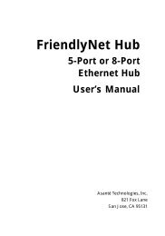
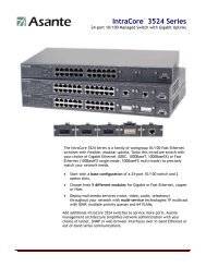
The <strong>IntraCore</strong> <strong>6524</strong> is a high performance solution for enterprise edge<br />
applications. The front panel of each switch includes 24 10/100 RJ-45 <strong>Ethernet</strong><br />
ports and two SC-connector Gigabit fiber ports. The system can operate as a<br />
stand-alone network or be used in combination with other <strong>IntraCore</strong> series<br />
switches in the backbone.<br />
Figure 1-1 The <strong>IntraCore</strong> <strong>6524</strong> front panel<br />
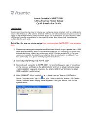
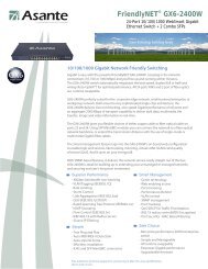
Features<br />
Figure 1-2 The <strong>IntraCore</strong> <strong>6524</strong> back panel<br />
The following table lists the major features of the <strong>IntraCore</strong> <strong>6524</strong> switch.<br />
Feature<br />
ASIC-Based Architecture<br />
High Performance<br />
6.4 Gbps Backplane<br />
Multiple Priority Queues<br />
GBIC Modules for Gigabit<br />
<strong>Ethernet</strong> Media Flexibility<br />
Installation Options<br />
Description<br />
ASIC-based packet processing provides wire speed performance<br />
on all interfaces.<br />
The system supports current requirements for multi-service voice,<br />
video, and data applications with bandwidth to spare.<br />
The “application aware” system ensures that mission critical applications<br />
get the bandwidth and priority they need, even under<br />
heavy traffic conditions. When network congestion occurs, low<br />
latency requirements are managed by the system.<br />
The two GBIC Gigabit <strong>Ethernet</strong> modules can be configured with<br />
any combination of 1000SX, 1000LX or 1000LX (Long Haul)<br />
GBIC interfaces. Either Asanté or third party GBIC interfaces can<br />
be used, and the interfaces can be “hot swapped.” This means that<br />
GBIC interfaces can be re-deployed based on the user’s applications.<br />
The system can be rack-mounted to save space.<br />
Page 1-5
Introduction<br />
Feature (Cont.)<br />
Security<br />
Web Based Management<br />
VLANs<br />
Multicast Control<br />
RMON<br />
Spanning Tree Protocol<br />
Y2K compliance<br />
Description (Cont.)<br />
Node summary tracks MAC and IP addresses per device, for multiple<br />
devices on each port. The Port Security feature provides perport<br />
security, allowing the network manager to specify which<br />
MAC is authorized on each port. Only the device with that MAC<br />
address is allowed to connect to that specific port.<br />
Built-in Web-based interface is provided for chassis management,<br />
module management, port-level control, and monitoring. The<br />
<strong>IntraCore</strong> <strong>6524</strong> can also be managed via Telnet, Console, or third<br />
party SNMP console.<br />
Supports up to 64 port-based VLANs (IEEE 802.1Q compliant)<br />
for security, logical network design, and the control of broadcast<br />
traffic. The 802.1Q standard specifies VLAN tagging for trunking<br />
VLANs from switch to switch, or switch to router. Compatible<br />
with all 802.1Q equipment for easy integration into existing networks.<br />
The <strong>IntraCore</strong> <strong>6524</strong> supports standards based IGMP snooping for<br />
control of multicast traffic generated by bandwidth-hungry applications<br />
such as video, ensuring maximum application and network<br />
performance.<br />
The administrator can use an RMON probe for in-depth traffic<br />
analysis, with support for four groups of RMON.<br />
Spanning Tree Protocol (STP) detects and eliminates data loops to<br />
prevent broadcast storms from overwhelming your network.<br />
All <strong>IntraCore</strong> series modules are Y2K compliant.<br />
Table 1-2<br />
<strong>IntraCore</strong> <strong>6524</strong> Features<br />
Page 1-6
Defaults and Specifications<br />
Defaults and Specifications<br />
The <strong>IntraCore</strong> <strong>6524</strong> is shipped with the following factory default settings and<br />
specifications:<br />
Configuration<br />
Default Setting<br />
Backplane Speed<br />
<strong>Switch</strong>ing Method<br />
Forwarding Rates:<br />
(64 byte packets)<br />
Buffer Size<br />
MAC Address Table<br />
Full-Duplex<br />
VLAN<br />
Spanning Tree Protocol<br />
Priority<br />
6.4Gbps.<br />
Store-and-forward<br />
<strong>Switch</strong>ed 10Mbps = 14,880 pps<br />
<strong>Switch</strong>ed 100Mbps = 148,810 pps<br />
<strong>Switch</strong>ed 1000Mbps = 1,488,100 pps<br />
8MB<br />
16K for MAC addresses on SRAM<br />
Standards-based auto-negotiation enabled<br />
64 port-based VLANs, GVRP support, 802.1Q VLAN Tagging<br />
802.1D, enabled<br />
802.1p, 8 levels mapped to 4 queues<br />
RMON Groups 1-3, 9<br />
SNMP<br />
MIB-II, Bridge MIB, RMON MIB, Asanté private MIBs<br />
Console Baud Rate 9600<br />
Password<br />
<strong>Asante</strong><br />
Table 1-3<br />
Defaults and Specifications<br />
Page 1-7
Introduction<br />
LEDs<br />
The following indicator lights are used on the <strong>IntraCore</strong> <strong>6524</strong>.<br />
LED<br />
Color and Meaning<br />
Power<br />
Link/Speed<br />
Duplex/Activity<br />
Link (Gigabit Ports)<br />
Green - Power is on when lit<br />
Green - 100Mbps<br />
Amber - 10Mbps<br />
Green -Full Duplex<br />
Amber - Half Duplex<br />
Blinking - Active<br />
Green - Connection and link have been made<br />
Blinking - Active<br />
Table 1-4<br />
LEDs and their meanings<br />
Page 1-8
2<br />
Installation and Setup<br />
This chapter explains how to install, connect, and configure the <strong>IntraCore</strong> <strong>6524</strong><br />
chassis and modules to work with your network. It also explains how to set up<br />
your <strong>IntraCore</strong> <strong>6524</strong> for management, either from a console, via telnet, via<br />
SNMP, or by using a Web browser.<br />
Installation Guidelines<br />
The following guidelines will help you prepare to install your <strong>IntraCore</strong> <strong>6524</strong> in<br />
such a way that it has the proper power supply and environment.<br />
Power Requirements<br />
The source electrical outlet should be installed near the <strong>IntraCore</strong> <strong>6524</strong> and<br />
easily accessible. It must also be properly grounded.<br />
Make sure the power source adheres to the following guidelines:<br />
❑<br />
❑<br />
❑<br />
Input voltage range: 90 to 254 VAC<br />
Frequency range: 47/63 Hz<br />
Maximum input AC Current: 2.0A at 115 VAC full load<br />
Environmental Requirements<br />
The <strong>IntraCore</strong> <strong>6524</strong> must be installed in a clean, dry, dust-free area with<br />
adequate air circulation to maintain the following environmental limits:<br />
❑ Operating Temperature: 0° to 40° C (32° to 104° F)<br />
❑ Storage Temperature: -40° to 70° C (-40° to 158° F)<br />
❑<br />
❑<br />
❑<br />
Relative Humidity: 8% to 90% non-condensing<br />
Sortgage RH: 0% to 95% non-condensing<br />
Storage Temperature: 5% to 85% non-condensing<br />
Avoid direct sunlight, heat sources, or areas with high levels of electromagnetic<br />
interference.<br />
Page 2-1
Installation and Setup<br />
Cooling and Airflow<br />
Do not restrict air flow by covering or obstructing air vents on the sides of the<br />
<strong>IntraCore</strong> <strong>6524</strong>.<br />
Installation Overview<br />
The table below shows the steps to install the <strong>IntraCore</strong> <strong>6524</strong>. The steps that<br />
are optional are labeled “optional” and the steps that are required are labeled<br />
“required.” The sections that follow explain each step in detail.<br />
Step<br />
1 (Required)<br />
2 (Required)<br />
3 (Required)<br />
4 (Required)<br />
5 (Required)<br />
Action to Be Taken<br />
Open the box and check the contents. See the Package Contents sheet<br />
for a complete list of the items included with your <strong>IntraCore</strong> <strong>6524</strong>.<br />
Install the <strong>IntraCore</strong> <strong>6524</strong> chassis in an equipment rack or wall rack, or<br />
prepare it for desktop placement. See page 2-3.<br />
Connect the power supply. See page 2-6.<br />
Connect network devices to the <strong>IntraCore</strong> <strong>6524</strong>. See page 2-7.<br />
Configure the <strong>IntraCore</strong> <strong>6524</strong> for management capabilities.<br />
See page 2-8.<br />
Table 2-1<br />
Installation Overview<br />
Page 2-2
Chassis Installation/Placement<br />
Chassis Installation/Placement<br />
The <strong>IntraCore</strong> <strong>6524</strong> can be installed in a standard 19-inch equipment rack. It<br />
can also be placed on a stable horizontal surface.<br />
▲<br />
The equipment rack or desk on which you install your<br />
<strong>IntraCore</strong> <strong>6524</strong> must be secure and stable. Equipment racks<br />
must be fastened to the floor; desks must be resting on a<br />
flat, stable surface.<br />
Installation in an Equipment Rack<br />
To install the unit in an equipment rack, use the following procedure:<br />
Safety Precautions for Rack Installation<br />
▲ Important! Before continuing, disconnect all cables from<br />
the <strong>IntraCore</strong> <strong>6524</strong>.<br />
Equipment Rack Guidelines<br />
Guideline<br />
Size<br />
Ventilation<br />
Clearance<br />
Specification<br />
Width; 17.75 inches (45.1 cm).<br />
Depth: 19.25 inches (48.9 cm) to 32 inches (81.3 cm).<br />
Ensure that the rack is installed in a room where the temperature remains<br />
below 40° C (104° F). Ensure also that there are no obstructions, such as<br />
other equipment or cables, blocking airflow to or from the <strong>IntraCore</strong> <strong>6524</strong><br />
vents.<br />
In addition to providing clearance for ventilation, ensure that there is adequate<br />
clearance for servicing the <strong>IntraCore</strong> <strong>6524</strong> from the front.<br />
Table 2-2<br />
Equipment Rack Guidelines<br />
Page 2-3
Installation and Setup<br />
Equipment Rack Installation Procedure<br />
To mount the <strong>IntraCore</strong> <strong>6524</strong> in an equipment rack:<br />
1 Place the <strong>IntraCore</strong> <strong>6524</strong> on a flat, stable surface.<br />
2 Locate a rack-mounting bracket (supplied) and place it over<br />
the mounting holes on one side of the unit.<br />
3 Insert six screws (supplied) into the holes and tighten with a<br />
Phillips screwdriver. Do not use fewer than six screws for<br />
this mounting.<br />
4 For the other side of the unit, repeat the two previous steps.<br />
5 Place the unit in the equipment rack.<br />
6 Secure the unit by screwing its mounting brackets to the<br />
equipment rack. Use a minimum of four screws for this<br />
purpose.<br />
▲ Important! Make sure the unit is supported until all<br />
the mounting screws for each bracket are secured to the<br />
equipment rack. Failure to do so could cause the unit to<br />
fall, resulting in personal injury or damage to the unit,<br />
or both.<br />
Free-Standing/Desktop Placement<br />
The <strong>IntraCore</strong> <strong>6524</strong> has four rubber feet on the bottom of the case that allow<br />
for free-standing placement of the unit.<br />
For free-standing/desktop placement:<br />
1 Attach the four rubber pads (supplied) to the bottom of<br />
each corner of the <strong>IntraCore</strong> <strong>6524</strong> case.<br />
2 Place the unit on a flat surface with a minimum area of<br />
17.1” x 13.5” (434.3 mm x 342.9 mm) and support capacity<br />
of 22lbs(10kg).<br />
3 Make sure there is enough ventilation space between the<br />
<strong>IntraCore</strong> <strong>6524</strong> and surrounding objects.<br />
Page 2-4
Chassis Installation/Placement<br />
Installing GBIC Interfaces<br />
If you have installed Gigabit <strong>Ethernet</strong> switch modules, you must install GBIC<br />
interfaces. Instructions for installing, removing, and maintaining GBIC<br />
interfaces are provided in this section.<br />
◆ Note: GBICs are hot-swappable.<br />
Installing a GBIC<br />
To install a GBIC interface into a Gigabit <strong>Ethernet</strong> module:<br />
1 Remove the GBIC from its protective packaging.<br />
2 Grip the sides of the GBIC with your thumb and forefinger,<br />
then insert the GBIC into the slot on the face of the Gigabit<br />
<strong>Ethernet</strong> module.<br />
3 Slide the GBIC into the slot until you hear or feel a click.<br />
The click indicates that the GBIC is locked into the slot.<br />
4 When you are ready to attach the fiber-optic cable, remove<br />
the plugs from the GBIC and save them for future use.<br />
Removing a GBIC<br />
To remove a GBIC interface from a Gigabit <strong>Ethernet</strong> module:<br />
1 Disconnect the fiber-optic cable from the GBIC SC-type<br />
connector.<br />
2 Release the GBIC from the slot by simultaneously squeezing<br />
the plastic tabs on both sides of the GBIC.<br />
3 Slide the GBIC out of the slot.<br />
4 Install the plugs in the GBIC optical bores, and place the<br />
GBIC in protective packaging.<br />
Page 2-5
Installation and Setup<br />
GBIC Care and Handling<br />
Follow these GBIC maintenance guidelines:<br />
❑ Unnecessary removal and insertion of a GBIC can lead to its premature<br />
failure. A GBIC has a lifetime of 100 to 500 removals/insertions.<br />
❑ GBICs are static-sensitive. To prevent ESD damage, follow your normal<br />
board and component handling procedures.<br />
❑ GBICs are dust-sensitive. When the GBIC is stored or when a fiberoptic<br />
cable is not plugged in, always keep plugs in the GBIC optical<br />
bores.<br />
❑ Use an alcohol swab or Kim-Wipe to clean the ferrules of the optical<br />
connector. The most common source of contaminants in the optical<br />
bores is debris picked up from the optical connectors.<br />
Connecting Power<br />
To connect power to the <strong>IntraCore</strong> <strong>6524</strong>, use the following procedure:<br />
▲ Important! Carefully review the power requirements on<br />
page 2-1 before connecting power to the <strong>IntraCore</strong> <strong>6524</strong>.<br />
1 Plug one end of the supplied power cord into the power<br />
connector on the back of the unit.<br />
2 Plug the other end into a grounded AC outlet.<br />
The front panel LEDs blink and the Power LED illuminates.<br />
The <strong>IntraCore</strong> <strong>6524</strong> is ready for connection to the<br />
network.<br />
▲ Important! If the power does not come on, refer to<br />
Appendix A, “Troubleshooting.”<br />
Page 2-6
Connecting to the Network<br />
Connecting to the Network<br />
The <strong>IntraCore</strong> <strong>6524</strong> unit may be connected to an <strong>Ethernet</strong> network, with the<br />
unit either powered on or off. Use the following procedure to make your<br />
network connections.<br />
1 Connect network devices to the <strong>IntraCore</strong> <strong>6524</strong>, following<br />
the cable guidelines outlined below.<br />
2 After the unit is connected to the network, it can be configured<br />
for management capabilities. See “Configuring for<br />
Management” on page 2-8.<br />
10/100BaseX Ports Cabling Procedures<br />
The 24 10/100 ports on the <strong>IntraCore</strong> <strong>6524</strong> allow for the connection of<br />
10Base-T or 100Base-TX network devices. The ports are compatible with<br />
IEEE 802.3 and 802.3u standards.<br />
▲ Important! The <strong>IntraCore</strong> <strong>6524</strong> must be located within<br />
100 meters of its attached 10Base-T or 100Base-TX<br />
devices.<br />
Connecting To<br />
Network Station<br />
Repeater/Hub/<strong>Switch</strong><br />
Repeater/Hub/<strong>Switch</strong>’s<br />
Uplink port<br />
Cable Required<br />
Category 5 UTP (Unshielded Twisted-Pair) straight-through cable<br />
(100 meters maximum) with RJ-45 connectors.<br />
Category 5, UTP cross-over cable (100 meters maximum) with RJ-<br />
45 connectors.<br />
Category 5, UTP straight-through cable (100 meters maximum)<br />
with RJ-45 connectors.<br />
Table 2-3<br />
10/100BaseTX cabling requirements<br />
Page 2-7
Installation and Setup<br />
1000BaseX Ports Cabling Procedures<br />
Cabling requirements for the 2-port Gigabit <strong>Ethernet</strong> modules depend on the<br />
type of GBIC interface that has been installed. Use the following chart to<br />
determine the cabling requirements for your GBIC.<br />
Connecting To<br />
1000BaseSX GBIC<br />
1000BaseLX Long<br />
Haul GBIC<br />
1000BaseLX GBIC<br />
Cable Required<br />
Cables with SC-type fiber connectors: 62.5 micron multimode<br />
fiber media up to 275 meters long, or 50 micron multimode fiber<br />
media up to 550 meters long.<br />
Cables with SC-type fiber connectors: 10 micron single mode fiber<br />
media up to 100 kilometers long.<br />
Cables with SC-type fiber connectors: 10 micron single mode fiber<br />
media up to 5 kilometers long.<br />
Table 2-4<br />
1000BaseX cabling requirements<br />
Configuring for Management<br />
To use the <strong>IntraCore</strong> <strong>6524</strong> as a managed switch, the <strong>IntraCore</strong> <strong>6524</strong> must be<br />
configured with an IP address. You can accomplish this configuration in one of<br />
two ways:<br />
❑ automatically using BootP (default)<br />
❑ manually via the unit’s Console port<br />
▲ Important! For security reasons, you should also change<br />
the SNMP community strings before putting the <strong>IntraCore</strong><br />
<strong>6524</strong> on your network. For instructions, see “Changing<br />
Community Strings” on page 3-17.<br />
BootP Configuration<br />
The <strong>IntraCore</strong> <strong>6524</strong> is shipped with BootP support. If your network contains a<br />
BootP server configured with available, valid IP addresses, BootP allows the<br />
<strong>IntraCore</strong> <strong>6524</strong> to be configured automatically with an IP address when the<br />
<strong>IntraCore</strong> <strong>6524</strong> is connected to the network and is powered on.<br />
▲ Important! BootP configuration works only if the<br />
<strong>IntraCore</strong> <strong>6524</strong> does not have an IP address assigned to it.<br />
Page 2-8
Configuring for Management<br />
Use the following procedure to set up BootP:<br />
1 Make sure your network has a BootP server configured with<br />
a valid IP address entry for the <strong>IntraCore</strong> <strong>6524</strong>.<br />
2 When the <strong>IntraCore</strong> <strong>6524</strong> is connected to the network and<br />
is powered on, it automatically transmits a BootP request<br />
across the network (up to 10 times) until it receives a valid<br />
IP address from the BootP server.<br />
3 After an IP address is received, the <strong>IntraCore</strong> <strong>6524</strong> can be<br />
managed via in-band access. For more information, see<br />
Chapter 3, “Configuration.”<br />
To verify that a valid IP address was received, try to ‘ping’ the <strong>IntraCore</strong> <strong>6524</strong>.<br />
If you can access the <strong>IntraCore</strong> <strong>6524</strong>, it is properly configured with an IP<br />
address.<br />
For more information on using BootP, see “Bootstrap Configuration” on<br />
page 3-12.<br />
Connecting To a Console<br />
To make the cable connection from a terminal to the console port of the<br />
<strong>IntraCore</strong> <strong>6524</strong>use the following procedure:<br />
1 Using a straight-through RS-232 cable with a 9-pin male<br />
D-subminiature plug at one end, connect a terminal or<br />
workstation (PC or Macintosh) running a terminal emulator<br />
to the console port on the back of the <strong>IntraCore</strong> <strong>6524</strong>.<br />
2 Make sure both units are powered on.<br />
If using a PC with a terminal emulator, make sure it is configured<br />
with the following terminal settings:<br />
❑ Baud: 9600<br />
❑ Data Bits: 8<br />
❑ Parity: None<br />
❑ Stop Bits: 1<br />
❑ Flow Control: None<br />
3 Once connected, the Local Management Main Menu<br />
appears on the terminal screen.<br />
Page 2-9
Installation and Setup<br />
For further information on setting an IP address for configuration of a terminal,<br />
or a computer running a VT100 terminal or emulator (such as HyperTerminal,<br />
ProComm, or ZTerm), see “System IP Configuration” on page 3-10.<br />
Management Options<br />
The <strong>IntraCore</strong> <strong>6524</strong> can be managed using any of the following methods:<br />
Method Type Description<br />
Console<br />
Telnet<br />
(four sessions maximum)<br />
HTTP Server<br />
SNMP-Based Network<br />
Management Software<br />
Out-of-band<br />
management<br />
In-band<br />
management<br />
In-band<br />
management<br />
In-band<br />
management<br />
Local connection to the <strong>IntraCore</strong> <strong>6524</strong> via the console<br />
port<br />
Remote connection over the network to the <strong>IntraCore</strong><br />
<strong>6524</strong> via telnet session<br />
Remote connection to the <strong>IntraCore</strong> <strong>6524</strong> via a Web<br />
browser<br />
Remote connection to the <strong>IntraCore</strong> <strong>6524</strong> via any<br />
SNMP-based network management application<br />
Table 2-5 Management Methods<br />
The rest of this section describes how to connect to the <strong>IntraCore</strong> <strong>6524</strong> using<br />
either out-of-band or in-band management.<br />
Out-of-Band Management<br />
Out-of-band network management allows you to configure, manage, and<br />
monitor the <strong>IntraCore</strong> <strong>6524</strong> and all of the installed modules. You can perform<br />
these functions by attaching a terminal (or a terminal emulator) to the Console<br />
port on the management engine and using the menu-driven Local Management<br />
Interface.<br />
Out-of-band network management is guaranteed even when the in-band<br />
<strong>Ethernet</strong> network is down.<br />
To access the <strong>IntraCore</strong> <strong>6524</strong> Local Management Interface using out-of-band<br />
management, first follow the procedure in “Connecting To a Console” (above),<br />
then follow the instructions in “Local Management Interface” on page 3-2.<br />
Page 2-10
Management Options<br />
In-Band Management<br />
In-band network management allows you to configure, manage, and monitor<br />
the <strong>IntraCore</strong> <strong>6524</strong> over the <strong>Ethernet</strong> network.<br />
You can manage the <strong>IntraCore</strong> <strong>6524</strong> by:<br />
❑<br />
❑<br />
Connecting with a telnet program and using the Local Management<br />
Interface<br />
Connecting with any World Wide Web browser, and using the Web<br />
Management Interface<br />
❑ Connecting with any SNMP-based network management application<br />
and using its interface<br />
To manage the <strong>IntraCore</strong> <strong>6524</strong> via in-band management, use the following<br />
procedure:<br />
1 Make sure the network to which the <strong>IntraCore</strong> <strong>6524</strong> is connected<br />
is functioning.<br />
2 Make sure the <strong>IntraCore</strong> <strong>6524</strong> is configured with valid IP<br />
information. See “Configuring for Management” earlier in<br />
this chapter.<br />
3 Connect to the <strong>IntraCore</strong> <strong>6524</strong> via telnet, with a Web<br />
browser, or with any SNMP-based network management<br />
application.<br />
Telnet<br />
Use a network connection to any PC and enter the telnet command to<br />
access the <strong>IntraCore</strong> <strong>6524</strong>. The password prompt of the Local Management<br />
Interface appears. Follow the instructions in “Local Management Interface” on<br />
page 3-2.<br />
◆ Note: Almost all management screens using a telnet connection<br />
are identical to those of the out-of-band console interface.<br />
On the Main Menu, however, there is a q option for<br />
closing the connection to the <strong>IntraCore</strong> <strong>6524</strong>.<br />
Page 2-11
Installation and Setup<br />
Web Browser<br />
For information on managing the <strong>IntraCore</strong> <strong>6524</strong> with a Web browser, refer to<br />
Chapter 5, “Web Browser Management.”<br />
▲ Important! The Web browser interface to the <strong>IntraCore</strong><br />
<strong>6524</strong> is disabled by default.<br />
SNMP-Based Management<br />
For information on managing the <strong>IntraCore</strong> <strong>6524</strong> with SNMP-based<br />
management software, refer to Chapter 4, “Advanced Management,” and your<br />
SNMP software manual.<br />
The Asanté private MIB for the <strong>IntraCore</strong> <strong>6524</strong> is available from the Asanté ftp<br />
site, ftp://ftp.asante.com/MIBS/, or you can copy it from the Installation CD-<br />
ROM.<br />
Access to Remote Network Monitoring (RMON) features is available only by<br />
using an SNMP manager. See “SNMP and RMON Management” on page 4-7<br />
for details.<br />
Page 2-12
3<br />
Configuration<br />
This chapter describes how to manage the <strong>IntraCore</strong> <strong>6524</strong> using the Local<br />
Management Interface via an out-of-band console connection or an in-band<br />
telnet connection.<br />
This chapter contains the following sections:<br />
❑ Local Management Interface<br />
❑ Viewing General Information<br />
❑ Configuration Menu<br />
❑ System Administration Configuration<br />
❑ System IP Configuration<br />
❑ Bootstrap Configuration<br />
❑ SNMP Configuration<br />
❑ Port Configuration<br />
❑ Advanced Port Configuration<br />
❑ Global Port Configuration<br />
❑ Unicast Forwarding Database Configuration<br />
❑ Port Mirroring Configuration<br />
❑ Image File Downloading Configuration<br />
❑ System Reset Configuration<br />
❑ Viewing the System Log<br />
❑ User Interface Configuration<br />
❑ Viewing Statistics<br />
Page 3-1
Configuration<br />
Local Management Interface<br />
The <strong>IntraCore</strong> <strong>6524</strong> Local Management Interface is a menu-driven application<br />
that allows you to configure, manage, and monitor the and each of the ports in<br />
its different modules.<br />
The Local Management Interface can be accessed via two methods:<br />
❑ Out-of-band connection to the Console port<br />
❑ In-band connection via Telnet (four sessions maximum)<br />
For instructions on how to connect to the <strong>IntraCore</strong> <strong>6524</strong>, see “Management<br />
Options” on page 2-10.<br />
The rest of this chapter describes the Local Management Interface.<br />
Logging In<br />
When you connect to the Local Management Interface, the “Enter Password”<br />
prompt appears. Enter your password, then press Return. The Main Menu<br />
appears.<br />
▲ Important! The default password is <strong>Asante</strong>. The password<br />
is case-sensitive; enter it exactly as shown. For information<br />
on changing the password, see “Changing the<br />
Password” on page 3-48.<br />
Page 3-2
Local Management Interface<br />
Main Menu<br />
After logging in, the Main Menu appears, as shown in Figure 3-1.<br />
=================================================================<br />
<strong>IntraCore</strong> <strong>6524</strong> Local Management System Version 1.02D<br />
Compiled Date: Jun 23 2000 19:53:29<br />
<strong>Asante</strong> Technologies, Inc.<br />
Copyright (c) 1999 <strong>Asante</strong> Technologies, Inc.<br />
=================================================================<br />
Main Menu<br />
<br />
g<br />
c<br />
s<br />
q<br />
<br />
General Information<br />
Configuration<br />
Statistics<br />
Close connection<br />
Command><br />
Figure 3-1 Local Management Main Menu<br />
From the Main Menu, you can access three submenus:<br />
❑ General Information (see page 3-4)<br />
❑ Configuration (see most of this chapter)<br />
❑ Statistics (see page 3-50)<br />
If you are using Telnet, a fourth option for closing the connection is available<br />
as well.<br />
Accessing a Submenu<br />
To access a submenu, type the command letter that corresponds with the option<br />
you need to use. For example, type g for General Information.<br />
Exiting a Submenu<br />
To exit a submenu, type q.<br />
To exit a command line without changing the configuration setting (e.g., the<br />
“Set Password” option in the User Interface Configuration Menu), press ctrl-c.<br />
Page 3-3
Configuration<br />
Viewing General Information<br />
The General Information Screen displays the current operating information of<br />
the <strong>IntraCore</strong> <strong>6524</strong>, such as its name, IP address, and boot information.<br />
To view General Information, type g from the Main Menu. A screen similar to<br />
Figure 3-2 appears.<br />
<strong>IntraCore</strong> <strong>6524</strong> General Information Menu<br />
System up for: 000day(s), 00hr(s), 43min(s), 47sec(s)<br />
Software Version<br />
Bank 1 Image Version/Date: 1.00E/Aug 23 2000 19:04:37<br />
Bank 2 Image Version/Date: 1.00F/Aug 24 2000 14:09:25 (Running)<br />
System Information<br />
PROM Image Version/Date: 1.04 /Aug 10 2000 19:38:11<br />
DRAM Size: 16.0MB Flash Size: 8.0MB<br />
EEPROM Size: 32KB Console Baud Rate: 9600 bps<br />
Administration Information<br />
System Name: <strong>Asante</strong> <strong>IntraCore</strong> <strong>Switch</strong><br />
System Location: ZLabs Head Office<br />
System Contact: CLB<br />
System MAC Address, IP Address, Subnet Mask and Router<br />
MAC Address: 00:00:94:C6:F3:EF<br />
IP Address: 192.168.52.208<br />
Subnet Mask: 255.255.255.0<br />
Router: 192.168.52.1<br />
Bootstrap Configuration<br />
Boot Load Mode: LOCAL<br />
Press any key to continue...<br />
Figure 3-2 General Information screen<br />
◆ Note: The information displayed on this screen is read-only.<br />
To exit the General Information Screen, press any key on your keyboard.<br />
Page 3-4
Viewing General Information<br />
Table 3-1 describes each parameter in the General Information screen.<br />
Setting<br />
System Up Time<br />
Bank 1 Image Version/<br />
Date<br />
Bank 2 Image Version/<br />
Date<br />
Prom Image Ver/Date<br />
DRAM Size<br />
EEPROM Size<br />
Flash Size<br />
Console Baud Rate<br />
System Name<br />
System Location<br />
System Contact<br />
MAC Address<br />
IP Address<br />
Description<br />
The amount of time the system has been running since last reset<br />
or power on.<br />
The version and compilation date of the runtime code that is<br />
stored in Bank 1. “(Running)” indicates code is currently active.<br />
The version and compilation date of the runtime code that is<br />
stored in Bank 2.<br />
The version and compilation date of the PROM.<br />
The size in megabytes (MB) of the unit’s Dynamic Random<br />
Access Memory.<br />
The size in megabytes (MB) of the unit’s EEPROM.<br />
The size, in MB, of the switch’s flash memory, or non-volatile<br />
RAM.<br />
The current rate which data transfers to the console from the<br />
<strong>IntraCore</strong> <strong>6524</strong>.<br />
The name assigned to the <strong>IntraCore</strong> for network purposes.<br />
The physical location of the <strong>IntraCore</strong>.<br />
Person responsible for configuration of the unit.<br />
The hardware address of the <strong>IntraCore</strong> <strong>6524</strong>; this address cannot<br />
be changed<br />
The unit’s IP (Internet Protocol) address.<br />
Subnet Mask The IP subnet mask for the <strong>IntraCore</strong> <strong>6524</strong>.<br />
Router<br />
Boot Load Mode<br />
The IP address of the default gateway router to which the switch<br />
belongs.<br />
The current method in use for loading the switch’s software.<br />
Table 3-1<br />
General Information settings<br />
Page 3-5
Configuration<br />
Configuration Menu<br />
The Configuration Menu allows you to manage and configure the <strong>IntraCore</strong><br />
<strong>6524</strong> and each of its ports.<br />
To access the Configuration Menu, type c from the Main Menu. The<br />
Configuration Menu appears, as shown in Figure 3-3.<br />
<strong>IntraCore</strong> <strong>6524</strong> Configuration Menu<br />
<br />
a<br />
i<br />
b<br />
n<br />
p<br />
s<br />
d<br />
t<br />
v<br />
c<br />
m<br />
f<br />
r<br />
l<br />
u<br />
q<br />
<br />
System Administration Configuration<br />
System IP Configuration<br />
Bootstrap Configuration<br />
SNMP Configuration<br />
Port Configuration<br />
Spanning Tree Configuration<br />
Unicast Forwarding Database Configuration<br />
Security Management<br />
VLAN Management<br />
IP Multicast Traffic Management<br />
Port Mirroring Configuration<br />
File Downloading Configuration<br />
System Reset Options<br />
System Log<br />
User Interface Configuration<br />
Return to previous Menu<br />
Command><br />
Figure 3-3 Configuration Menu<br />
Accessing a Submenu<br />
To access a submenu, type the command letter that corresponds with the<br />
configuration option you need to use. For example, type a for the System<br />
Administration Configuration Menu.<br />
Configuration Menu Options<br />
Table 3-2 describes each of the options in the Configuration Menu.<br />
Menu Item<br />
System Administration<br />
Configuration<br />
System IP Configuration<br />
Description<br />
Displays and allows you to change the name, location, and contact<br />
information for the <strong>IntraCore</strong> <strong>6524</strong>. See page 3-8.<br />
Displays and allows changing the IP Address of the <strong>IntraCore</strong><br />
<strong>6524</strong>. This address is for network access to the switch.<br />
See page 3-10.<br />
Page 3-6
Configuration Menu<br />
Menu Item (Cont.)<br />
Bootstrap Configuration<br />
SNMP Configuration<br />
Port Configuration<br />
Spanning Tree Configuration<br />
Unicast Forwarding<br />
Database Configuration<br />
Security Management<br />
Description (Cont.)<br />
Allows you to change boot bank and method for loading switch<br />
software, or change downloading parameters. See page 3-12.<br />
Displays and allows you to change the SNMP (Simple Network<br />
Management Protocol) parameters of the <strong>IntraCore</strong> <strong>6524</strong> such as<br />
read/write community strings. See page 3-16.<br />
Allows you to configure manually each of the switch’s ports for<br />
speed, connection, link mode, and auto-negotiation. Also displays<br />
overall port status. See page 3-20.<br />
Displays and allows you to change Spanning Tree parameters, to<br />
make sure you prevent loops in network paths. See page 4-1.<br />
Allows you to display the forwarding database, search the database<br />
for MAC or IP addresses, or set the age-out time for MAC<br />
addresses. See page 3-30.<br />
Allows you to use various features such as Duplicate IP traps, for<br />
port security. See page 4-9.<br />
VLAN Management Allows you to set up virtual networks. See page 4-18.<br />
IP Multicast Traffic<br />
Management<br />
Port Mirroring<br />
Configuration<br />
File Downloading Configuration<br />
System Reset Options<br />
System Log<br />
User Interface Configuration<br />
Return to Previous Menu<br />
Allows you to set up group transmission. See page 4-37.<br />
Allows you to set a mirror port so that you can connect a traffic<br />
analyzer to the switch and monitor traffic on the mirrored port.<br />
See page 3-34.<br />
Allows you to download an image file for the purpose of upgrading<br />
the <strong>IntraCore</strong> <strong>6524</strong> software. See page 3-37.<br />
Allows you to reset the switch by a “warm” reboot, or arrange for<br />
an automatic reset up to 24 hours in advance. See page 3-43.<br />
Allows you to view a record of any major system events or errors<br />
that have occurred on the <strong>IntraCore</strong> <strong>6524</strong>. See page 3-45<br />
Allows you to set the idle time-out period and password for console<br />
and telnet access, and enable or disable HTTP access. See page 3-46.<br />
Allows you to exit the Configuration Menu and return to the<br />
Main Menu.<br />
Table 3-2<br />
Configuration Menu Options<br />
Most of the configuration options are described in detail in the rest of this<br />
chapter. The more advanced options are discussed in Chapter 4, “Advanced<br />
Management.”<br />
Page 3-7
Configuration<br />
System Administration Configuration<br />
The System Administration Configuration Menu displays and allows you to<br />
change the name of the <strong>IntraCore</strong> <strong>6524</strong>, its location, and the contact<br />
information.<br />
To access the System Administration Configuration Menu, type a in the<br />
Configuration Menu. A screen similar to Figure 3-4 appears.<br />
<strong>IntraCore</strong> <strong>6524</strong> System Admin. Configuration Menu<br />
Description: <strong>Asante</strong> Technologies, Inc. <strong>IntraCore</strong> <strong>6524</strong>-2G<br />
Versions: FW(1.00F)<br />
Object ID: 1.3.6.1.4.1.298.2.2.24<br />
Name: <strong>Asante</strong> <strong>IntraCore</strong> <strong>Switch</strong><br />
Location: ZLabs Main Office<br />
Contact: CLB<br />
<br />
n Set System Name<br />
l Set System Location<br />
c Set System Contact Information<br />
q Return to Previous Menu<br />
Command><br />
Figure 3-4 System Administration Configuration Menu<br />
Current Settings<br />
The following table describes each setting on the System Administration<br />
Configuration Menu.<br />
Setting<br />
Description<br />
Name<br />
Location<br />
Contact<br />
The name of the <strong>IntraCore</strong> <strong>6524</strong> (up to 64 characters, including<br />
spaces).<br />
Place where you have installed the <strong>IntraCore</strong> <strong>6524</strong> (up to 64 characters,<br />
including spaces).<br />
The name of the person or entity responsible for the <strong>IntraCore</strong><br />
<strong>6524</strong> (up to 64 characters, including spaces).<br />
Table 3-3<br />
System Administration settings<br />
Page 3-8
System Administration Configuration<br />
Changing System Administration Info<br />
To change the name, location, or contact information for the <strong>IntraCore</strong> <strong>6524</strong>,<br />
use the following procedure:<br />
1 Open the System Administration Configuration Menu by<br />
typing a in the Configuration Menu.<br />
2 Type the command letter of the item to be changed in the<br />
System Administration Configuration Menu.<br />
3 At the prompt, type the information you want to change.<br />
See Table 3-3 for a description of each parameter.<br />
◆ Note: Each parameter is limited to 64 characters,<br />
including spaces.<br />
To cancel a selected option, press ctrl-c at the command<br />
prompt.<br />
4 Press Return.<br />
The <strong>IntraCore</strong> <strong>6524</strong> system administration information<br />
changes take effect.<br />
5 Type q to quit and return to the Configuration Menu.<br />
Page 3-9
Configuration<br />
System IP Configuration<br />
The System IP Configuration Menu displays and allows you to change the<br />
information needed to access the <strong>IntraCore</strong> <strong>6524</strong> over the network via in-band<br />
management.<br />
To access the System IP Configuration Menu, type i in the Configuration<br />
Menu. A screen similar to Figure 3-5 appears.<br />
<strong>IntraCore</strong> <strong>6524</strong> System IP Configuration Menu<br />
System MAC Address: 00:00:92:CC:BB:AA<br />
System IP Address: 192.168.54.240<br />
System Subnet Mask: 255.255.255.0<br />
System Default Router: 192.168.54.2<br />
<br />
i Set IP Address<br />
m Set Subnet Mask<br />
r Set Default Router<br />
q Return to Previous Menu<br />
Command><br />
Figure 3-5 System IP Configuration Menu<br />
▲ Important! By default, each address is set to 0.0.0.0.<br />
Current Settings<br />
Table 3-4 describes each setting on the System IP Configuration Menu.<br />
Setting<br />
Description<br />
System IP Address The IP (Internet Protocol) address of the <strong>IntraCore</strong> <strong>6524</strong>.<br />
System Subnet Mask<br />
The filter that determines how the <strong>IntraCore</strong> <strong>6524</strong> IP address is<br />
split into network and host portions.<br />
System Default Router The IP address of the default router for the <strong>IntraCore</strong> <strong>6524</strong>.<br />
Table 3-4<br />
System IP settings<br />
Page 3-10
System IP Configuration<br />
Changing System IP Information<br />
To change the IP address, subnet mask, or default router of the <strong>IntraCore</strong> <strong>6524</strong>,<br />
use the following procedure:<br />
1 Open the System IP Configuration Menu by typing i in the<br />
Configuration Menu.<br />
2 Type the command letter of the option you want to change.<br />
3 Type the new address at the prompt.<br />
See Table 3-4 for a description of each address.<br />
▲ Important!<br />
Follow the format:<br />
number.number.number.number<br />
To cancel a change, press ctrl-c at the command prompt.<br />
4 Press Return.<br />
The IP setting change for the <strong>IntraCore</strong> <strong>6524</strong> takes effect.<br />
5 Type q to quit and return to the Configuration Menu.<br />
Page 3-11
Configuration<br />
Bootstrap Configuration<br />
The Bootstrap Configuration Menu displays (and allows you to change) the<br />
bootstrap parameters used for loading the software for the <strong>IntraCore</strong> <strong>6524</strong> at<br />
startup, and for downloading a new version of software when one is issued.<br />
To access the Bootstrap Configuration Menu, type b in the Configuration<br />
Menu. If the Load Mode is set to Local, a screen similar to Figure 3-6 appears.<br />
<strong>IntraCore</strong> <strong>6524</strong> Bootstrap Configuration Menu<br />
Bank 1 Image Version/Date: E/Aug 23 2000 19:04:37 (Running)<br />
Bank 2 Image Version/Date: F/Aug 24 2000 14:09:25<br />
Load Mode: Local<br />
Boot Bank: 2<br />
<br />
r Set Load Mode to REMOTE<br />
a Toggle Boot Bank<br />
q Return to previous menu<br />
Command><br />
Figure 3-6 Local Bootstrap Configuration Menu<br />
When the <strong>IntraCore</strong> <strong>6524</strong> is powered on, it loads its software via one of two<br />
methods: locally (via its internal flash memory, which is the default setting) or<br />
remotely over the network.<br />
▲ Important! The default Load Mode setting for the<br />
<strong>IntraCore</strong> <strong>6524</strong> is Local.<br />
Image Banks<br />
The <strong>IntraCore</strong> <strong>6524</strong> has two banks to store its runtime software. The banks are<br />
referred to as bank 1 and bank 2.<br />
Either of these banks may be the Boot Bank, which is the bank from which the<br />
runtime code will be loaded the next time the <strong>IntraCore</strong> <strong>6524</strong> is booted.<br />
When downloading new runtime image codes, you may specify either of the<br />
two banks as the Destination Bank in which the new code will be loaded.<br />
Loading Software Locally<br />
The <strong>IntraCore</strong> <strong>6524</strong> will always boot locally unless you set it to boot load<br />
remotely (see “Loading Software Remotely” on page 3-13). It would then<br />
download the new image code and reset to load locally. To specify the Boot<br />
Page 3-12
Bootstrap Configuration<br />
Bank the <strong>IntraCore</strong> <strong>6524</strong> will use when it boots locally, use the following<br />
procedure:<br />
1 Open the Bootstrap Configuration Menu by typing b in the<br />
Configuration Menu.<br />
2 Type a in the Bootstrap Configuration Menu if you need to<br />
toggle the Boot Bank setting for the next boot. Typically,<br />
you will want to set the boot bank to be the one on which<br />
the latest version of the Image resides.<br />
The <strong>IntraCore</strong> <strong>6524</strong> is set to load software locally from its flash memory. This<br />
occurs whenever the unit is powered on or reset.<br />
Loading Software Remotely<br />
To set the <strong>IntraCore</strong> <strong>6524</strong> to download its software over the network from a<br />
remote server, use the following procedure:<br />
1 Open the Local Bootstrap Configuration Menu by typing b<br />
in Configuration Menu.<br />
2 Open the Remote Bootstrap Configuration Menu by typing<br />
r in the Local Bootstrap Configuration Menu. The menu<br />
appears, as shown in Figure 3-7.<br />
<strong>IntraCore</strong> <strong>6524</strong> Bootstrap Configuration Menu<br />
Bank 1 Image Version/Date: E/Aug 23 2000 19:04:37 (Running)<br />
Bank 2 Image Version/Date: F/Aug 24 2000 14:09:25<br />
Load Mode: Remote<br />
Boot Mode: TFTP only<br />
Boot Server IP: 192.168.54.150<br />
Boot File Name: c:\base\newcrc.ima<br />
Retry Count: 5<br />
Boot Bank: 1<br />
<br />
b Set Boot Mode to BOOTP-TFTP<br />
t Set Boot Mode to TFTP only<br />
l Set Load Mode to LOCAL<br />
s Set Boot Server IP Address<br />
f Set Boot File Name<br />
c Set Remote Boot Retry Count<br />
a Toggle Boot Bank<br />
q Return to Previous Menu<br />
Command><br />
Figure 3-7 Remote Bootstrap Configuration Menu<br />
Page 3-13
Configuration<br />
Current Settings<br />
Table 3-5 explains each setting on the Remote Bootstrap Configuration Menu.<br />
Setting<br />
Running Image Version/<br />
Date<br />
Description<br />
The version and compilation date of runtime code that is currently<br />
running on the <strong>IntraCore</strong> <strong>6524</strong>.<br />
Load Mode The current method for loading software for the <strong>IntraCore</strong> <strong>6524</strong>.<br />
Remote — Loads the image file from a server on the network.<br />
Local — Executes the software image file from the internal flash<br />
memory of the <strong>IntraCore</strong> <strong>6524</strong> (default setting; the <strong>IntraCore</strong><br />
<strong>6524</strong> automatically reverts to this setting after downloading a new<br />
software file).<br />
Boot Mode<br />
The method for requesting the image file from the network. This<br />
option is available only if you have selected Remote Load Mode.<br />
BootP-TFTP — Sets the <strong>IntraCore</strong> <strong>6524</strong> to request an IP address<br />
from a BootP server AND to download the software’s image file<br />
through TFTP (Trivial File Transfer Protocol).<br />
▲ Important! To use this option, the <strong>IntraCore</strong><br />
<strong>6524</strong> IP address must be set to 0.0.0.0.<br />
TFTP ONLY — Sets the <strong>IntraCore</strong> <strong>6524</strong> to only download the<br />
software image file through TFTP.<br />
▲ Important! To use this option, the switch must<br />
already have an assigned IP address and the Load<br />
Mode must be set to Remote.<br />
Boot Server IP<br />
Boot File Name<br />
Retry Count<br />
Boot Bank<br />
The Internet Protocol (IP) address of the TFTP server providing<br />
the TFTP capabilities on your network. Not Available if Boot<br />
Mode is BootP-TFTP.<br />
The name of the file you are going to request for download. Not<br />
available if boot mode is BootP/TFTP.<br />
Number of attempts the <strong>IntraCore</strong> <strong>6524</strong> makes to download the<br />
image file if errors occur. The default is 5.<br />
Number of the destination bank for the image file you are downloading<br />
(1 or 2).<br />
Table 3-5<br />
Bootstrap Settings<br />
Page 3-14
Bootstrap Configuration<br />
3 Type b to set the Boot Mode to BootP-TFTP, or type t to<br />
set Boot Mode to TFTP only. If you choose BootP-TFTP<br />
mode, the options for setting the IP Address of the TFTP<br />
server and the Boot File Name become unavailable; in this<br />
case, skip Steps 4-7 and go on to Step 8.<br />
4 Type s in the Bootstrap Configuration Menu, to select the<br />
option Set Boot Server IP Address.<br />
5 At the prompt, type the IP address of the remote boot server<br />
that contains the switch’s software image file. Then press<br />
Return. The Bootstrap Configuration Menu appears.<br />
6 Type f to select the option Set Boot File Name.<br />
7 Type the software’s file name/network path at the prompt.<br />
8 Press Return.<br />
◆ Note: If you decide to use Local Load Mode rather<br />
than Remote, type l. The Local Bootstrap Configuration<br />
Menu appears, as shown in Figure 3-6.<br />
The <strong>IntraCore</strong> <strong>6524</strong> is now set to download its software remotely from the<br />
network. This will occur the next time the unit is powered on or reset.<br />
Page 3-15
Configuration<br />
SNMP Configuration<br />
The SNMP Configuration Menu allows you to configure the unit’s read and<br />
write community strings, and to enable or disable authentication traps. This<br />
menu also allows you to specify which of your network management stations<br />
will receive traps from the .<br />
The s option in the Configuration Menu displays the SNMP (Simple Network<br />
Management Protocol) Configuration Menu, as shown in<br />
Figure 3-8.<br />
For further details on using SNMP and RMON for remote management of<br />
your network, see Chapter 4, “Advanced Management.”<br />
▲ Important! Be sure to change the SNMP community<br />
strings in order to prevent unauthorized access to management<br />
information.<br />
<strong>IntraCore</strong> <strong>6524</strong> SNMP Configuration Menu<br />
SNMP Read Community: public<br />
SNMP Write Community: private<br />
Trap Authentication: Enabled<br />
SNMP Trap Receivers:<br />
IP Address<br />
Community<br />
1. 192.168.54.150 private<br />
2. 192.168.54.110 Sarah<br />
3. <br />
4. <br />
<br />
r Set SNMP Read Community<br />
w Set SNMP Write Communtiy<br />
t Toggle Trap Authentication Enable/Disable<br />
a Add/Update SNMP Trap Receiver<br />
d Delete SNMP Trap Receiver<br />
q Return to Previous Menu<br />
Command><br />
Figure 3-8 SNMP Configuration Menu<br />
Page 3-16
SNMP Configuration<br />
Current Settings<br />
Table 3-6 describes each setting on the SNMP Configuration Menu.<br />
Setting<br />
SNMP Read Community<br />
SNMP Write Community<br />
Trap Authentication<br />
SNMP Trap Receivers<br />
Description<br />
The string that defines access rights for reading SNMP data<br />
objects. The default is public.<br />
The string that defines access rights for writing SNMP data<br />
objects. The default is private.<br />
The status of the SNMP agent for authentication trap generation.<br />
The default is disabled.<br />
The IP addresses of the network management stations that can<br />
receive traps from the <strong>IntraCore</strong> <strong>6524</strong>. Normally, these addresses<br />
are the same as your network management software systems’ IP<br />
addresses.<br />
▲<br />
Important! A maximum of four trap receivers<br />
is allowed.<br />
Table 3-6<br />
SNMP Settings<br />
Changing Community Strings<br />
To change the <strong>IntraCore</strong> <strong>6524</strong> community strings, use the following procedure:<br />
1 Open the SNMP Configuration Menu by typing n in the<br />
Configuration Menu.<br />
2 To change the read community string, type r. To change the<br />
write community string, type w.<br />
3 At the prompt, type a new community string.<br />
For a description of read and write community strings, see<br />
Table 3-6.<br />
To cancel a selected option, press ctrl-c at the command<br />
prompt.<br />
4 Press Return. The new string takes effect.<br />
5 Type q to quit and return to the Configuration Menu.<br />
Page 3-17
Configuration<br />
Enabling Authentication Traps<br />
The <strong>IntraCore</strong> <strong>6524</strong> can be set to generate authentication traps. Authentication<br />
traps are messages sent across the network to an SNMP network management<br />
station. They alert you when someone attempts to read or change data without<br />
the proper community string.<br />
To set the <strong>IntraCore</strong> <strong>6524</strong> to generate traps, use the following procedure:<br />
1 Open the SNMP Configuration Menu by typing n in the<br />
Configuration Menu.<br />
2 To toggle trap authentication to Enabled, type a.<br />
To cancel the change, press ctrl-c at the command prompt.<br />
3 Press Return. The new setting takes effect.<br />
4 Type q to quit and return to the Configuration Menu.<br />
Adding or Updating a Trap Receiver<br />
Trap receivers are network management stations designated to receive traps<br />
from the <strong>IntraCore</strong> <strong>6524</strong>.<br />
▲ Important! The maximum number of trap receivers that<br />
can be set is four.<br />
To add or update a trap receiver entry, use the following procedure:<br />
1 Open the SNMP Configuration Menu by typing n in the<br />
Configuration Menu.<br />
2 Type a to Add a Trap Receiver. An IP prompt appears.<br />
3 Type the new or updated IP address of the network management<br />
station you want to receive traps, then press Return.<br />
To cancel an entry, press ctrl-c at the command prompt.<br />
4 Type the trap receiver’s community string at the prompt for<br />
it, then press Return again.<br />
The trap receiver entry is added or updated. Type q to<br />
return to the Configuration Menu.<br />
Page 3-18
SNMP Configuration<br />
Deleting a Trap Receiver<br />
Use the following procedure to delete a trap receiver you have previously<br />
designated:<br />
1 Open the SNMP Configuration Menu by typing n in the<br />
Configuration Menu.<br />
2 Type d to Delete a Trap Receiver. A prompt for the entry<br />
of the trap receiver appears.<br />
3 Enter the number of the entry you want to delete (1,2,3, or<br />
4) and press Return.<br />
The trap receiver is deleted from the SNMP Trap Receivers list.<br />
Page 3-19
Configuration<br />
Port Configuration<br />
The Port Configuration Menu allows you to manually configure each port of<br />
the <strong>IntraCore</strong> <strong>6524</strong> for port speed, duplex, and auto-negotiation. It also<br />
provides an overview of the entire <strong>IntraCore</strong> <strong>6524</strong> system’s port operating<br />
status.<br />
To access the Port Configuration Menu, type p in the Configuration Menu. A<br />
screen similar to Figure 3-9 appears.<br />
<strong>IntraCore</strong> <strong>6524</strong> Basic Port Configuration Menu Module: [1] Port: [01]<br />
Operating Status: +---+--- -------- -------- --<br />
Auto Negotiation: ******** *-****** ******** --<br />
Speed/Duplex: hhhhhhhH hhhhhhHH hhhhhhhh GG<br />
Port Status: Enabled<br />
Link Status: Up (RJ45-TX)<br />
Auto-Neg: Enabled[ABCD] Link Speed: 100 Mbps (Half Duplex)<br />
<br />
h Help for legends<br />
t Toggle Port Status Enable/Disable<br />
u Toggle Auto-Negotiation/<strong>Manual</strong><br />
l Toggle 10M/100M bps Link Speed<br />
d Toggle Half/Full Duplex<br />
o Modify Auto-Negotiation Advertisement<br />
r Restart Auto-Negotiation<br />
a Advanced Port Configuration<br />
g Global Port Configuration<br />
q Return to Previous Menu<br />
Command><br />
Select port Next port Prev port<br />
Figure 3-9 Port Configuration Menu<br />
Page 3-20
Port Configuration<br />
Viewing Legends for Configuration Settings<br />
To see legends explaining the symbols used for both the Basic and Global<br />
Port Configuration Menu settings, type h. A screen appears, as shown in<br />
Figure 3-10.<br />
Legends for port status:<br />
Legends for port speed & duplex:<br />
X - Absent<br />
f - 10 Mbps & full duplex<br />
- - Link down F - 100 Mbps & full duplex<br />
D - Disabled by Mgmt Action<br />
h - 10 Mbps & half duplex<br />
d - Disabled by Security Violation H - 100 Mbps & half duplex<br />
B - Blocking G - 1 Gbps & full duplex<br />
S - Listening<br />
R - Learning<br />
Legends for port priority:<br />
+ - Forwarding (The range is from 0 to 7)<br />
M - Mirror Port<br />
0 - priority 0 (lowest)<br />
Legends for Enable/Disable State: 1 - priority 1<br />
- - Disabled 2 - priority 2<br />
* - Enabled 3 - priority 3<br />
4 - priority 4<br />
Legends for Auto-Negotiation Advertisement: 5 - priority 5<br />
6 - priority 6<br />
A - 100Base-TX full duplex mode<br />
7 - priority 7 (highest)<br />
B - 100Base-TX half duplex mode<br />
C - 10Base-T full duplex mode<br />
D - 10Base-T half duplex mode<br />
Press any key to continue...<br />
Figure 3-10 Legends for all Port Configuration Menus<br />
Page 3-21
Configuration<br />
Current Port Settings<br />
The current module and port for which statistics are displayed is shown in the<br />
top right corner of the Port Configuration Menu. Table 3-7 describes each<br />
setting on the Port Configuration Menu.<br />
Setting<br />
Module Number<br />
Port Number<br />
Operating Status<br />
Auto Negotiation<br />
Link Speed/Duplex<br />
Port Status<br />
Link Status<br />
Auto-Neg<br />
Link Speed<br />
Description<br />
The number of the module of which the selected port is a member.<br />
(Always module 1)<br />
The number of the port for which parameters are shown.<br />
This field displays status symbols for each of the current module’s<br />
ports. For details, see the legend in Figure 3-10.<br />
This field displays disabled/enabled symbols for each of the current<br />
ports. For details, see the legend in Figure 3-10.<br />
This field displays speed/duplex setting symbols for each of the<br />
current ports. For details, see the legend in Figure 3-10.<br />
Tells whether the selected port is enabled or disabled.<br />
Tells whether the selected port’s link is up or down. ‘Up’ indicates<br />
a network device is connected to the port. ‘Down’ indicates that<br />
either a device isn’t connected or that the device is powered down.<br />
The port’s link speed and duplex mode are in parentheses.<br />
Tells whether auto-negotiation is enabled or disabled for the<br />
selected port, and for which modes, A, B, C, or D. For details, see<br />
the legend in Figure 3-10.<br />
Tells the speed and duplex mode of the port’s current link.<br />
Table 3-7<br />
Port Configuration Menu settings<br />
Page 3-22
Port Configuration<br />
Enabling or Disabling a Port<br />
The enabling or disabling of a port is a manual operation that can be used to<br />
isolate a network device that might be causing problems on the network, or to<br />
prevent unauthorized use of a port or station.<br />
To enable or disable a port, use the following procedure:<br />
1 Access the Port Configuration Menu by typing p in the<br />
Configuration Menu.<br />
2 To select the port you want to enable or disable, type s, n, or<br />
p in the Basic Port Configuration Menu.<br />
3 To toggle the port’s connection to either enabled or disabled<br />
status, type t.<br />
The port’s status is changed immediately, and it is reflected in the Port<br />
Configuration Menu’s Port Status indication and the Operating Status symbol<br />
for the port.<br />
Configuring Auto-Negotiation<br />
Auto-negotiation is a feature of the Fast <strong>Ethernet</strong> standard that enables two<br />
devices on a common segment to communicate their transmission speed<br />
capabilities. This feature allows the devices to determine and use their highest<br />
common speed and best communication parameters.<br />
▲ Important! By default, all of the ports are set to Auto<br />
Negotiation.<br />
To enable auto-negotiation, or return to manual-setting mode, use the<br />
following procedure:<br />
1 Access the Port Configuration Menu by typing p in the<br />
Configuration Menu.<br />
2 To select the port for which you want to set the auto-negotiation<br />
mode, in the Basic Port Configuration Menu, type s,<br />
n, or p.<br />
3 To toggle the port’s auto-negotiation mode to Enabled or to<br />
return it to <strong>Manual</strong>, type u.<br />
The Auto Negotiation status changes immediately, and is displayed on the Auto<br />
Negotiation line near the top of the Port Configuration Menu.<br />
▲ Important! If you change the port’s status from <strong>Manual</strong><br />
to Enabled you must type r to restart auto-negotiation.<br />
Page 3-23
Configuration<br />
Configuring a Port <strong>Manual</strong>ly<br />
If you have changed the Auto Negotiation status of a port to <strong>Manual</strong>, as<br />
described in the previous section, you can toggle the link speed from 10Mbps to<br />
100Mbps and back, and toggle the port from half to full duplex and back.<br />
Toggling Port Link Speed<br />
Use the following procedure to toggle the port’s link speed:<br />
1 Access the Port Configuration Menu by typing p in the<br />
Configuration Menu.<br />
2 To select the port for which you want to set the link speed,<br />
in the Basic Port Configuration Menu, type s, n, or p.<br />
3 To toggle the port’s link speed, type l.<br />
The link speed is changed immediately, and the change is reflected in the Link<br />
Speed line near the top of the Port Configuration Menu.<br />
Toggling Half to Full Duplex<br />
Half duplex mode allows transmission in two directions on the same channel,<br />
but only in one direction at a time. Full duplex mode allows transmission in<br />
two directions on the same channel at the same time.<br />
▲ Important! To use full duplex mode, the device to which<br />
the port is connected must support and be configured for<br />
duplex mode.<br />
Use the following procedure to change the duplex mode setting for a port that is<br />
in <strong>Manual</strong> status:<br />
1 Access the Port Configuration Menu by typing p in the<br />
Configuration Menu.<br />
2 To select the port for which you want to set the duplex<br />
mode, in the Basic Port Configuration Menu, type s, n,<br />
or p.<br />
3 To toggle the port’s duplex mode, type d.<br />
The duplex mode is changed immediately, and the change is reflected in the<br />
Link Speed/Duplex line near the top of the Port Configuration Menu.<br />
Page 3-24
Port Configuration<br />
Configuring 1000BaseX Ports<br />
Because 1000BaseX ports are always in full duplex mode, the only<br />
configuration option for 1000BaseX ports is enabling and disabling the port.<br />
Enabling or Disabling a Port<br />
Enabling or disabling a port is a manual operation. You can enable or disable a<br />
port to isolate network devices that may be causing problems on the network or<br />
to prevent unauthorized use of a port or station.<br />
To enable or disable a port, use the following procedure:<br />
1 Access the Port Configuration Menu by typing p in the<br />
Configuration Menu.<br />
2 In the Basic Port Configuration Menu, use s, n, or p to<br />
select the port you want to enable or disable.<br />
3 Type t to toggle the port’s connection to either enabled or<br />
disabled status, as desired.<br />
The port’s status is changed immediately, and it is reflected in the Port<br />
Configuration Menu’s Port Status indication and the Operating Status symbol<br />
for the port.<br />
Page 3-25
Configuration<br />
Advanced Port Configuration<br />
The Advanced Port Configuration Menu allows you to control the port<br />
broadcast and multicast rate, to enable or disable 802.3x flow control, and to<br />
set the default priority of the port.<br />
To access the Advanced Port Configuration Menu, from the Port Configuration<br />
Menu, type a. The Advanced Port Configuration Menu<br />
appears, as shown in Figure 3-11.<br />
<strong>IntraCore</strong> <strong>6524</strong> Advanced Port Config Menu Module: [1] Port: [01]<br />
Operating Status: +------- -------- -------- --<br />
Flow Ctrl: -------- -------- -------- --<br />
Class of Service: -******* ******** ******** **<br />
Priority: 00000000 00000000 00000000 00<br />
Flow Control:<br />
Disabled<br />
IEEE 802.1p Traffic Class Of Service: Disabled<br />
Port Default Priority: 0<br />
<br />
h Help for legends<br />
f Toggle 802.3x Flow Control Enable/Disable<br />
c Toggle Traffic Class Of Service (COS) Enable/Disable<br />
i Set Port Default Priority<br />
q Return to Previous Menu<br />
Command><br />
Select port Next port Prev port<br />
Figure 3-11 Advanced Port Configuration Menu<br />
The following subsections explain the configuration options in the Advanced<br />
Port Configuration Menu.<br />
Page 3-26
Advanced Port Configuration<br />
Current Settings<br />
The settings shown in the top portion of the Advanced Port Configuration<br />
Menu are described in Table 3-8.<br />
Setting<br />
Module Number<br />
Operating Status<br />
Flow Control<br />
Class of Service<br />
Priority<br />
Description<br />
The number of the module of which the selected port is a member.<br />
(Always module 1)<br />
This field displays status symbols for each of the current module’s<br />
ports. For details, see the legend in Figure 3-10.<br />
The status of flow control for the current port.When enabled, it<br />
allows you to control traffic and avoid congestion, such as when<br />
the port is receiving too much traffic for the available buffer<br />
resources.<br />
The status of the class of service for the current port.<br />
The priority ranking for the port regarding data transmission during<br />
periods of peak or heavy on the traffic. Ports with higher priority<br />
take precedence when there is traffic congestion.<br />
Table 3-8<br />
Advanced Port Configuration Menu settings<br />
Enabling or Disabling 802.3x Flow Control<br />
Use the following procedure to control traffic and avoid congestion, such as<br />
when there is a shortage of buffer resources for the port. Flow control is<br />
accomplished by means of standard PAUSE control frames for each port,<br />
independent of all others. Before you can enable flow control for a port, that<br />
port must be configured to operate in Full Duplex mode.<br />
If you enable flow control on a port, and that port runs short of buffer<br />
resources, the port will transmit PAUSE frames. When it receives them, the link<br />
partner obeys these PAUSE frames. When the low-resource situation is relieved,<br />
the port sends out PAUSE frames with zero time values. This ends the pause<br />
state that was imposed on the end-station.<br />
To enable flow control, take the following steps.<br />
1 Access the Port Configuration Menu by typing p in the<br />
Configuration Menu.<br />
2 In the Basic Port Configuration Menu, type a to open the<br />
Advanced Port Configuration Menu.<br />
Page 3-27
Configuration<br />
3 To select the port for which you want to enable or disable<br />
flow control, type s, n, or p.<br />
4 To toggle flow control for the selected port, type f.<br />
In the Advanced Port Configuration Menu, the Flow Control symbol for the<br />
selected port reflects its change in state, as does the 802.3x Flow Control<br />
setting.<br />
▲ Important! When using this method of flow control,<br />
the link partner must be configured to recognize PAUSE<br />
frames.<br />
Setting Port Class of Service<br />
To set a port’s class of service, take the following steps.<br />
1 Access the Port Configuration Menu by typing p in the<br />
Configuration Menu.<br />
2 In the Basic Port Configuration Menu, type a to open the<br />
Advanced Port Configuration Menu.<br />
3 To select the port for which you want to enable or disable<br />
flow control, type s, n, or p.<br />
4 To toggle flow control for the selected port, type c.<br />
In the Advanced Port Configuration Menu, the Class of Service symbol for the<br />
selected port reflects its change in state.<br />
Setting Port Default Priority<br />
This priority setting determines the order in which the port forwards packets.<br />
Each port is associated with a traffic class: zero (0) is the lowest, and the default<br />
priority level. Seven (7) is the highest priority level. Use the following procedure<br />
to set the priority for a port:<br />
1 Access the Port Configuration Menu by typing p in the<br />
Configuration Menu.<br />
2 In the Basic Port Configuration Menu, type a to open the<br />
Advanced Port Configuration Menu.<br />
3 Use s, n, or p to select the port for which you want to set<br />
the default priority.<br />
Page 3-28
Global Port Configuration<br />
4 Type i to set the priority for the selected port.<br />
5 Enter the priority, from 0 to 7, and press Return.<br />
The new default priority is shown on the Advanced Port Configuration Menu.<br />
Global Port Configuration<br />
The Global Port Configuration Menu allows you to simultaneously change the<br />
configuration information for all ports in a module.<br />
To change the port configuration for all ports in a module, use the following<br />
procedure:<br />
1 From the Configuration Menu, type p to access the Port<br />
Configuration Menu.<br />
2 From the Basic Port Configuration Menu, type g. The<br />
Global Port Configuration Menu appears, as shown in<br />
Figure 3-12.<br />
<strong>IntraCore</strong> <strong>6524</strong> Global Port Configuration Menu Module: [1] Port: [01]<br />
Operating Status: +------- -------- -------- --<br />
Auto Negotiation: ******** ******** ******** **<br />
Speed/Duplex: Hhhhhhhh hhhhhhhh hhhhhhhh hh<br />
Flow Ctrl: *------- -------- -------- --<br />
Class of Service: -******* ******** ******** **<br />
Priority: 00000000 00000000 00000000 00<br />
<br />
h<br />
t<br />
u<br />
l<br />
d<br />
o<br />
f<br />
i<br />
q<br />
Command><br />
<br />
Help for legends<br />
Select Global Ports Status Enable/Disable<br />
Select Global Auto-Negotiation/<strong>Manual</strong><br />
Select Global 10M/100M bps Link Speed<br />
Select Global Half/Full Duplex<br />
Modify Global Auto-Negotiation Advertisement<br />
Toggle Global 802.3x Flow Control Enable/Disable<br />
Set Global Port Devault Priority<br />
Return to Previous Menu<br />
Figure 3-12 Global Port Configuration Menu<br />
Follow the procedures in the following sections: “Port Configuration” on<br />
page 3-20 and “Advanced Port Configuration” on page 3-26.<br />
Page 3-29
Configuration<br />
Unicast Forwarding Database Configuration<br />
The Unicast Forwarding Database Configuration Menu allows you to view and<br />
search for addresses in the MAC Forwarding Table for the <strong>IntraCore</strong> <strong>6524</strong>. It<br />
also provides options for displaying MAC addresses and IP/MAC binding by<br />
individual port or by VLAN.<br />
The MAC Forwarding Table is a table of node addresses that the <strong>IntraCore</strong><br />
<strong>6524</strong> automatically builds by “learning.” It performs this task by monitoring<br />
the packets that pass through the <strong>IntraCore</strong> <strong>6524</strong>, checking the source and<br />
destination addresses, and then recording the source address information in the<br />
table.<br />
The <strong>IntraCore</strong> <strong>6524</strong> uses the information in this table to decide whether a<br />
frame should be forwarded to a particular destination port or “flooded” to all<br />
ports other than the received port. Each entry consists of three parts: the MAC<br />
address of the device, the port number on which it was received, and the VLAN<br />
number.<br />
◆ Note: The MAC address table can hold a maximum of<br />
8,192 entries.<br />
When you type d in the Configuration Menu, the Unicast Forwarding<br />
Database Configuration Menu appears, as shown in Figure 3-13.<br />
<strong>IntraCore</strong> <strong>6524</strong> Unicast Forwarding Database Configuration Menu<br />
Age-out Time:<br />
300 sec.<br />
MAC Address Count: 33<br />
IP Address Count: 21<br />
<br />
a Display All Forwarding Database With/Without IP<br />
p Display Forwarding Database By Port With/Without IP<br />
v Display Forwarding Database by VLAN With/Without IP<br />
m Search for MAC Address<br />
i Search for IP Address<br />
t Set Age-Out Time<br />
q Return to Previous Menu<br />
Command><br />
Figure 3-13 Unicast Forwarding Database Configuration Menu<br />
Page 3-30
Unicast Forwarding Database Configuration<br />
Current Settings<br />
Table 3-9 explains each setting on the Forwarding Database Configuration<br />
Menu.<br />
Setting<br />
Age-out Time<br />
MAC Address Count<br />
IP Address Count<br />
Description<br />
The number of seconds that addresses are retained in the table.<br />
The default is 300 seconds. The range is from 10 to 1,000,000.<br />
The number of entries currently in the MAC Address Table.<br />
The number of entries in the MAC Address Table that contain a<br />
corresponding IP address.<br />
Table 3-9<br />
Forwarding Database Configuration Menu settings<br />
Displaying the Forwarding Database<br />
Use the following procedure to view the Unicast Forwarding Database table.<br />
1 Open the Unicast Forwarding Database Configuration<br />
Menu by typing d in the Configuration Menu.<br />
2 Type either a, p, or v, depending on the range of MAC<br />
addresses you want to view.<br />
Type a to display the MAC addresses learned on all ports on<br />
the <strong>IntraCore</strong> <strong>6524</strong>.<br />
Type p to specify a port, then see the MAC addresses for<br />
that port only.<br />
Type v to specify a VLAN, then see the MAC addresses for<br />
the member ports of that VLAN only.<br />
3 At the prompt which appears, type y to see IP addresses in<br />
the display or type n to see the display without IP addresses,<br />
then press Return. The selected display appears.<br />
Figure 3-14 shows an example of the Unicast Forwarding Database table for all<br />
ports, without the IP displayed.<br />
Page 3-31
Configuration<br />
The Type field refers to the type of MAC address. The Type setting may be:<br />
❑ S — static (set by management, and will not age out)<br />
❑ D — dynamic (learned by the switch; will be aged out)<br />
❑ M — multiple (associated with multiple IP addresses, as in the case<br />
of a router)<br />
❑ I — Self (the MAC address of the <strong>IntraCore</strong> <strong>6524</strong>)<br />
Entry Type : ( D = Dynamic , S = Static , I = Self )<br />
+------+----+----+-----------------+---------+<br />
|Module|Port|Type| MAC Address | VLAN ID |<br />
+------+----+----+-----------------+---------+<br />
1 2 S 00:00:94:75:2A:21 0001<br />
1 6 D 00:00:94:9A:BF:54 0001<br />
1 6 D 00:00:94:B4:66:48 0001<br />
1 6 D 00:00:94:B4:7A:8D 0001<br />
1 6 D 00:00:94:B5:1B:B1 0001<br />
- -- I 00:00:94:DD:75:01 0001<br />
1 11 D 00:10:4B:36:91:AC 0001<br />
End of Summary, Quit<br />
Figure 3-14 Unicast Forwarding Database, all ports, without IP displayed<br />
Searching for a MAC Address<br />
The Unicast Forwarding Database can be searched by MAC address or by IP<br />
address. To search for a specific MAC or IP address, use the following<br />
procedure:<br />
1 Access the Unicast Forwarding Database Configuration<br />
Menu by typing d in the Configuration Menu.<br />
2 Type m to search for a MAC address.<br />
Type i to search for an IP address.<br />
3 Type the MAC or IP address at the prompt.<br />
4 Press Return.<br />
If the address is located, it is displayed, with its associated information, as<br />
shown in Figure 3-15. If the address is not located, a message appears, stating<br />
this.<br />
Page 3-32
Unicast Forwarding Database Configuration<br />
The MAC Address Search Summary<br />
==============================<br />
Port: 6<br />
Type:<br />
Dynamic<br />
MAC Address: 00:00:94:11:12:13<br />
VLAN ID: 0002<br />
IP Address: 192.168.54.111<br />
press any key to continue...<br />
Figure 3-15 MAC Address Search summary<br />
The Search Summary screen tells the location of the MAC or IP address, the<br />
module, port, and the domain name. Configuration information, such as the<br />
type, age, and priority are also displayed.<br />
Setting the MAC Address Age-Out Time<br />
This option sets the Age-Out Time for the MAC Forwarding Table.<br />
The Age-Out Time is the number of seconds that addresses remain in the table<br />
after being learned by the <strong>IntraCore</strong> <strong>6524</strong>. The default is 300 seconds.<br />
Use the following procedure to set the MAC address Age-Out Time.<br />
1 Access the Unicast Forwarding Database Configuration<br />
Menu by typing d in the Configuration Menu.<br />
2 Type t to set the MAC Address Age-Out Time.<br />
3 Enter the new Age-Out time (in seconds) at the prompt.<br />
4 Press Return.<br />
The MAC Address Age-Out Time is changed and is displayed at the top of the<br />
Unicast Forwarding Database Configuration Menu.<br />
Page 3-33
Configuration<br />
Port Mirroring<br />
Port mirroring allows you to configure the <strong>IntraCore</strong> <strong>6524</strong> to copy all traffic<br />
associated with one port (the Monitor Port) to a Mirror Port on the switch. You<br />
can connect the Mirror Port to a network analyzer or RMON probe for packet<br />
analysis. You can configure the Monitor Port to send either transmitted or<br />
received traffic to the Mirror Port.<br />
In the <strong>IntraCore</strong> <strong>6524</strong>, port 13 is always the Mirror Port. You can specify any<br />
other port to be a Monitor Port, except ports 25 and 26, the two Gigabit ports<br />
in the switch.<br />
To configure port mirroring in the <strong>IntraCore</strong> <strong>6524</strong>, type m in the<br />
Configuration Menu. A screen similar to Figure 3-16 appears.<br />
<strong>IntraCore</strong> <strong>6524</strong> Port Mirroring Configuration Menu Module: [1]<br />
System Port Mirroring Status: [Enabled]<br />
Mirror Port: [13]<br />
Monitor Port: [08]<br />
Port Traffic Monitor Type: [Port Receive Data]<br />
<br />
s<br />
t<br />
e<br />
q<br />
<br />
Set Monitor Port<br />
Toggle System Port Mirroring Enable/Disable<br />
Toggle Port Monitor Type Receive/Transmit Data<br />
Return to previous menu<br />
Command><br />
Figure 3-16 Port Mirroring Configuration Menu<br />
Page 3-34
Port Mirroring<br />
Current Options<br />
Table 3-10 describes the settings shown in the Port Mirroring Configuration<br />
Menu.<br />
Option<br />
System Port Mirroring<br />
Status<br />
Mirror Port<br />
Monitor Port<br />
Port Traffic Monitor<br />
Type<br />
Description<br />
Indicates the current status of port mirroring for the switch. If<br />
port mirroring is enabled, traffic from the Monitor Port will be<br />
copied to the Mirror Port.<br />
The port that mirrors the traffic from the Monitor Port. For the<br />
<strong>IntraCore</strong> <strong>6524</strong>, this is always port 13.<br />
The port being monitored.<br />
The type of traffic from the Monitor Port that is copied to the<br />
Mirror Port. Port Receive Data indicates monitoring of the traffic<br />
received by the Monitor Port. Port Send Data indicates monitoring<br />
of the traffic sent by the Monitor Port.<br />
Table 3-10<br />
Port Mirroring Configuration settings<br />
Enabling or Disabling System Port Mirroring<br />
To enable or disable port mirroring, use the following procedure:<br />
1 Type m in the Configuration menu to display the Port Mirroring<br />
Configuration menu.<br />
2 Type t to toggle System Port Mirroring.<br />
The change is reflected immediately in the settings shown at<br />
the top of the Port Mirroring Configuration menu. Note<br />
that if System Port Mirroring is Enabled, then the Mirror<br />
Port setting shows Port 13 as Mirror Port.<br />
Page 3-35
Configuration<br />
Specifying Port Traffic Monitor Type<br />
To specify whether to monitor port receive traffic or port send traffic, System<br />
Port Mirroring must be enabled. After enabling port mirroring, use the<br />
following procedure to specify the Port Traffic Monitor Type:<br />
1 Type m in the Configuration menu to display the Port Mirroring<br />
Configuration menu.<br />
2 Type e to toggle System Port Mirroring.<br />
The change is reflected immediately in the settings shown<br />
at the top of the Port Mirroring Configuration menu.<br />
Setting the Monitor Port<br />
To specify which port to monitor, use the following procedure:<br />
1 Type m in the Configuration menu to display the Port Mirroring<br />
Configuration menu.<br />
2 Type s and then follow the instructions to select the Monitor<br />
port.<br />
The change is reflected immediately in the settings shown<br />
at the top of the Port Mirroring Configuration menu.<br />
Page 3-36
Image File Downloading Configuration<br />
Image File Downloading Configuration<br />
The Image File Downloading Configuration Menu allows you to upgrade your<br />
<strong>IntraCore</strong> <strong>6524</strong> system easily, using either TFTP or X/Y/Z modem protocol.<br />
Type f in the Configuration Menu to see the Image File Downloading<br />
Configuration Menu, as shown in Figure 3-17.<br />
<strong>IntraCore</strong> <strong>6524</strong> File Downloading Configuration Menu<br />
<br />
t<br />
x<br />
q<br />
Command><br />
<br />
TFTP File Downloading Configuration<br />
X/Y/ZMODEM Image File Downloading Configuration<br />
Return to Previous Menu<br />
Figure 3-17 Image File Downloading Configuration Menu<br />
From the Image File Downloading Configuration Menu, select the<br />
downloading protocol. Type t to download the image file via TFTP or type x to<br />
download using the X/Y/Z modem protocol. The two subsections that follow<br />
describe downloading by each of the two protocols.<br />
When Asanté issues a new version of software for the <strong>IntraCore</strong> <strong>6524</strong>, you can<br />
obtain it from the Asanté World Wide Web site or by contacting Asanté<br />
Technical Support (see Appendix A, “Technical Support,” for details).<br />
Page 3-37
Configuration<br />
Image Downloading Through TFTP<br />
To download a new image file in-band through TFTP, type t in the Image File<br />
Downloading Configuration Menu (option g in the Configuration Menu). A<br />
screen similar to Figure 3-18 appears.<br />
<strong>IntraCore</strong> <strong>6524</strong> TFTP File Downloading Menu<br />
Bank 1 Image Version/Date 1.00E/Aug 23 2000 19:04:37<br />
Bank 2 Image Version/Date 1.00F/Aug 24 2000 14:09:25 (Running)<br />
File Type:<br />
Image<br />
Server IP: 192.168.52.211<br />
File Name:<br />
ic6k100f.ima<br />
Retry Count: 5<br />
Destination Bank: 1<br />
<br />
s Set Server IP Address<br />
f Set File Name<br />
d Download Image File to Destination Bank<br />
b Download and Reboot from the Image File<br />
r Set Retry count<br />
a Toggle Destination Bank<br />
q Return to Previous Menu<br />
Command><br />
Figure 3-18 TFTP Image File Downloading Menu<br />
Current Settings<br />
Table 3-11 describes each setting on the TFTP Image Downloading Menu.<br />
Setting<br />
Bank 1 Image Version/<br />
Date<br />
Bank 2 Image Version/<br />
Date<br />
Server IP<br />
File Name<br />
Retry Count<br />
Destination Bank<br />
Description<br />
The version number and compilation date of runtime code that is<br />
stored in memory bank 1 on the <strong>IntraCore</strong> <strong>6524</strong>.<br />
The version number and compilation date of runtime code that is<br />
stored in memory bank 2 on the <strong>IntraCore</strong> <strong>6524</strong>. The runtime<br />
code is currently running on this bank.<br />
IP address of network server containing software image file.<br />
The software image file’s name and network path.<br />
Number of attempts the switch will make to download image file.<br />
Number of the memory bank where the image file will download.<br />
Table 3-11<br />
TFTP Image Download Menu settings<br />
Page 3-38
Image File Downloading Configuration<br />
Performing a Software Upgrade at Runtime<br />
The software image file must be downloaded from a server on your network<br />
that is running a TFTP server application.<br />
▲ Important! Make sure the <strong>IntraCore</strong> <strong>6524</strong> is configured<br />
with an IP address. For details, see “Changing System IP<br />
Information” earlier in this chapter.<br />
To upgrade the <strong>IntraCore</strong> <strong>6524</strong> software via TFTP, use the following procedure:<br />
1 Access the TFTP Image File Downloading Configuration<br />
Menu by typing t in the Image File Downloading Configuration<br />
Menu.<br />
2 Type s to set the image server IP address.<br />
3 At the prompt, enter the IP address of the server containing<br />
the image file, then press Return.<br />
4 Type f to set the image file name.<br />
5 At the prompt, enter the image file’s name and path, then<br />
press Return.<br />
6 Type r to set the retry count.<br />
7 At the prompt, enter the number of attempts the <strong>IntraCore</strong><br />
<strong>6524</strong> will make to download the image file, then press<br />
Return.<br />
8 Select the Destination Image Bank by using the a option. In<br />
a typical situation, you will want to select the Bank on<br />
which the software is not currently running, as shown in<br />
Figure 3-18.<br />
9 To download the image file to the destination bank, type d.<br />
This option allows you to change the boot bank at a later<br />
time or to use the System Reset Configuration to schedule a<br />
reset, at which time the new software will be run.<br />
OR<br />
To download the image file and reset the switch, type b.<br />
This option immediately boots the <strong>IntraCore</strong> <strong>6524</strong> with the<br />
new version of software.<br />
10 Type q to return to the Image File Downloading Menu.<br />
Page 3-39
Configuration<br />
Serial Downloading Configuration<br />
The X/Y/Z Modem Image File Downloading Menu lets you download a new<br />
software image file for the <strong>IntraCore</strong> <strong>6524</strong> without interrupting the current<br />
operation.<br />
To download a new image through the <strong>IntraCore</strong> <strong>6524</strong> management module’s<br />
serial (console) port, type x in the Image File Downloading Configuration<br />
Menu. The X/Y/Z Modem Image File Downloading Menu appears, as shown<br />
in Figure 3-19.<br />
<strong>IntraCore</strong> <strong>6524</strong> X/Y/ZMODEM Image File Downloading Menu<br />
Bank 1 Image Version/Date 1.00E/Aug 23 2000 19:04:37<br />
Bank 2 Image Version/Date 1.00F/Aug 24 2000 14:09:25 (Running)<br />
Download Protocol: ZMODEM<br />
Current Baud Rate: 9600 bps<br />
Destination Bank: 1<br />
<br />
x Set download protocol to XMODEM<br />
y Set download protocol to YMODEM<br />
z Set download protocol to ZMODEM<br />
c Change Baud Rate Setting<br />
d Download File to Destination Bank<br />
b Download and Reboot from the Image File<br />
a Toggle Destination Bank<br />
q Return to Previous Menu<br />
Command><br />
Figure 3-19 X/Y/Z Modem Image File Downloading Menu<br />
Page 3-40
Image File Downloading Configuration<br />
Current Settings<br />
Table 3-12 describes the settings shown in the X/Y/Z Modem Image File<br />
Downloading Menu.<br />
Setting<br />
Bank 1 Image Version/<br />
Date<br />
Bank 2 Image Version/<br />
Date<br />
Download Protocol<br />
Current Baud Rate<br />
Destination Bank<br />
Description<br />
The version number and compilation date of runtime code that is<br />
stored in memory Bank 1 on the <strong>IntraCore</strong> <strong>6524</strong>.<br />
The version number and compilation date of runtime code that is<br />
stored in memory Bank 2 on the <strong>IntraCore</strong> <strong>6524</strong>.The (Running)<br />
designation indicates that the runtime code is currently running<br />
on this Bank.<br />
Current setting of the <strong>IntraCore</strong> <strong>6524</strong>’s serial download protocol.<br />
Transmission rate for the <strong>IntraCore</strong> <strong>6524</strong>’s serial port.<br />
Number of the memory bank where the image file will download.<br />
Table 3-12<br />
X/Y/Z Modem Image File Downloading settings<br />
Performing a Software Upgrade<br />
Use the following procedure to upgrade the <strong>IntraCore</strong> <strong>6524</strong> software through<br />
its serial (console) port.<br />
1 In the Image File Download Configuration Menu, type x to<br />
open the X/Y/Z Modem Image File Downloading Menu.<br />
2 Type x, y, or z to select the corresponding modem protocol.<br />
◆ Note: For information about these protocols, see the<br />
manual for your communications software.<br />
3 Type c to select the console baud rate. The Baud Rate Setting<br />
Menu appears, as shown in Figure 3-20. The maximum<br />
baud rate currently supported is 57,600 bps.<br />
Page 3-41
Configuration<br />
Current Baud Rate: 9600 bps<br />
Please select one from the following baud rate settings, or<br />
press any other key to quit:<br />
WARNING:<br />
<br />
a<br />
b<br />
c<br />
d<br />
e<br />
f<br />
g<br />
Choice><br />
The user must use the same baud rate setting of the terminal<br />
after he/she confirms to change the baud rate setting of the<br />
console in order to work correctly.<br />
<br />
Set Baud Rate to 1200 bps<br />
Set Baud Rate to 2400 bps<br />
Set Baud Rate to 4800 bps<br />
Set Baud Rate to 9600 bps<br />
Set Baud Rate to 19200 bps<br />
Set Baud Rate to 38400 bps<br />
Set Baud Rate to 57600 bps<br />
Figure 3-20 Baud Rate Menu<br />
4 Select one of the options in the above screen to select the<br />
required baud rate, and confirm it by typing y.<br />
◆ Note: The baud rate default for console management is<br />
9600 bps; in most cases the default will match the rate<br />
for the connected terminal. If you change the baud rate<br />
for the console port, the screen will display garbled data<br />
unless the connected terminal is set to the same rate.<br />
5 Type a to select the Destination Bank.<br />
6 To download the image file, use any serial communications<br />
software such as Procomm Plus, HyperTerminal, ZTerm,<br />
etc. For file transfer instructions, follow the instruction<br />
manual of the serial communications software.<br />
◆ Note: The terminal on which the serial communications<br />
software is running must have the same baud rate as the<br />
<strong>IntraCore</strong> <strong>6524</strong> management module console. The connection<br />
from the terminal to the switch console port<br />
must be an RS232C straight-through cable.<br />
7 Type d to download to the selected destination bank or b to<br />
download and reset.<br />
8 Type q to return to the previous menu after performing a<br />
successful download.<br />
Page 3-42
System Reset Configuration<br />
System Reset Configuration<br />
The System Reset Configuration Menu allows you to reset the <strong>IntraCore</strong> <strong>6524</strong><br />
by performing a “warm” reboot. It also allows you to schedule a reset up to 24<br />
hours in advance.<br />
To reset the <strong>IntraCore</strong> <strong>6524</strong>, type r in the Configuration Menu. A screen<br />
similar to Figure 3-21 appears.<br />
<strong>IntraCore</strong> <strong>6524</strong> System Reset Configuration Menu<br />
Reset Status: Stop<br />
Reset Type:<br />
Normal<br />
Reset Countdown: 1 sec.<br />
<br />
s Schedule Reset Time<br />
c Cancel Reset<br />
r Reset <strong>Switch</strong><br />
d Reset <strong>Switch</strong> to Factory Default<br />
i Reset <strong>Switch</strong> to Factory Default except IP and Bootstrap<br />
q Return to Previous Menu<br />
Command><br />
Figure 3-21 System Reset Configuration Menu<br />
Current Options<br />
Table 3-13 describes the settings shown in the System Reset Configuration<br />
Menu.<br />
Option<br />
Schedule Reset Time<br />
Cancel Reset<br />
Reset <strong>Switch</strong><br />
Reset <strong>Switch</strong> to Factory<br />
Default<br />
Reset <strong>Switch</strong> to Factory<br />
Default except IP &<br />
Bootstrap<br />
Description<br />
Number of seconds until the scheduled reset.<br />
Stops the scheduled reset.<br />
Performs a warm reboot to reset the <strong>IntraCore</strong> <strong>6524</strong> immediately.<br />
Resets the <strong>IntraCore</strong> <strong>6524</strong> to the original factory settings.<br />
Resets the <strong>IntraCore</strong> <strong>6524</strong> to the original factory settings without<br />
modifying the IP and Bootstrap configuration.<br />
Table 3-13<br />
System Reset Configuration options<br />
Page 3-43
Configuration<br />
Resetting the <strong>IntraCore</strong> <strong>6524</strong><br />
To reset the <strong>IntraCore</strong> <strong>6524</strong>, use the following procedure:<br />
1 Open the System Reset Menu by typing r in the Configuration<br />
Menu.<br />
2 Type r, d or i. Typing r resets the <strong>IntraCore</strong> <strong>6524</strong>. Typing r<br />
resets the to its current configuration. Typing d resets the<br />
<strong>IntraCore</strong> <strong>6524</strong> to the factory default. Typing i resets the<br />
<strong>IntraCore</strong> <strong>6524</strong> to the factory default without affecting its<br />
IP and Bootstrap configuration.<br />
3 Type y to confirm the reset or type n to cancel the reset.<br />
◆ Note: During the scheduled reset operation, you can see<br />
the reset countdown decrement by refreshing the screen.<br />
Scheduling a System Reset<br />
You can schedule the <strong>IntraCore</strong> <strong>6524</strong> to automatically perform a reset from one<br />
second up to 24 hours (86,400 seconds) in advance.<br />
To schedule a reset, use the following procedure:<br />
1 Open the System Reset Menu by typing r in the Configuration<br />
Menu.<br />
2 Type s to schedule a reset time (within the specified range).<br />
3 Enter the number of seconds the <strong>IntraCore</strong> <strong>6524</strong> will wait<br />
before it automatically resets.<br />
▲ Important! The maximum number of seconds that<br />
can be entered is 86,400 (24 hours).<br />
4 Press Return.<br />
The <strong>IntraCore</strong> <strong>6524</strong> will reset automatically after the number of seconds you<br />
specified.<br />
Page 3-44
Viewing the System Log<br />
Viewing the System Log<br />
The <strong>IntraCore</strong> <strong>6524</strong> system log records and displays any major system events on<br />
the switch, such as fatal errors, plugging in or removing a module, etc.<br />
To view the system log, use the following procedure:<br />
1 Type l in the Configuration Menu. The System Log Menu<br />
appears, as shown in Figure 3-22.<br />
System Log Menu<br />
<br />
l<br />
c<br />
q<br />
<br />
Display System Log<br />
Clear System Log<br />
Return to previous menu<br />
Command><br />
Figure 3-22 System Log Menu<br />
2 Type d to display the current system log, as shown in<br />
Figure 3-23.<br />
<strong>IntraCore</strong> <strong>6524</strong> System Log Summary<br />
====================================================================<br />
No. D: H: M: S Event<br />
1. 000:00:00:00 Reset NVDB sections to factory default<br />
2. 000:00:00:07 Spanning Tree Task Disabled<br />
3. 000:00:32:53 Spanning Tree Task Enabled<br />
4. 000:00:33:45 Spanning Tree Task Disabled<br />
5. 000:00:41:11 Spanning Tree Task Enabled<br />
6. 000:00:00:00 Reset NVDB section 0 to factory default<br />
7. 000:00:32:51 Spanning Tree Task Disabled<br />
8. 000:00:33:08 Spanning Tree Task Enabled<br />
Quit Next Page<br />
Figure 3-23 System Log Summary<br />
The system log displays any major system events that have<br />
occurred on the <strong>IntraCore</strong> <strong>6524</strong>. If no major events have<br />
occurred, “System up” messages are displayed.<br />
◆ Note: The system log holds a maximum of 64 entries.<br />
3 Press any key to display the next page of System Log information.<br />
Page 3-45
Configuration<br />
Clearing the System Log<br />
Use the following procedure to clear all entries from the current System Log.<br />
1 Open the System Log Menu by typing l in the Configuration<br />
Menu.<br />
2 Type c to clear the current System Log.<br />
New entries will begin to accrue as events occur.<br />
User Interface Configuration<br />
The User Interface Configuration Menu lets you set the idle time-out periods<br />
for both the console and telnet user interfaces, change the password used for<br />
logging in to the Local Management Interface, and enable or disable the Web<br />
server.<br />
To display the User Interface Configuration Menu, as shown in Figure 3-24,<br />
type u in the Configuration Menu.<br />
<strong>IntraCore</strong> <strong>6524</strong> User Interface Configuration Menu<br />
Console UI Idle Time Out: 5 min<br />
Telnet UI Idle Time Out: 5 min<br />
HTTP Server Status: ENABLED<br />
Telnet Session Status:<br />
Session Status Source IP<br />
1 Active 192.168.54.240<br />
2 Inactive <br />
3 Inactive <br />
4 Inactive <br />
<br />
c<br />
t<br />
p<br />
o<br />
q<br />
Command><br />
<br />
Set Console UI Time Out<br />
Set Telnet UI Time Out<br />
Change Administrator Password<br />
TOggle to Enable/Disable HTTP Server<br />
Return to previous menu<br />
Figure 3-24 User Interface Configuration Menu<br />
Page 3-46
User Interface Configuration<br />
Current Settings<br />
Table 3-14 describes the settings in the User Interface Configuration Menu.<br />
Setting<br />
Console UI Idle Time-out<br />
Telnet UI Idle Time-out<br />
HTTP Server Status<br />
Telnet Session Status<br />
Telnet Session Source IP<br />
Description<br />
Duration of time the console will remain idle before returning to<br />
the Main Menu.<br />
Duration of time the console will remain idle before closing the<br />
Telnet connection.<br />
Enabled or Disabled.<br />
Inactive or Active, depending on whether session is in progress.<br />
The IP address of the device being used for telnet management.<br />
Table 3-14<br />
UI Time-out Settings<br />
Setting Console Idle Time-out Period<br />
Use the following procedure to set the console idle time-out.<br />
1 Type c in the User Interface Configuration Menu.<br />
A prompt for the number of minutes is displayed.<br />
2 Enter the desired idle time-out in minutes.<br />
◆ Note: The default time-out is 5 minutes. Range for<br />
time-out is 0-60 minutes (0 indicates no time-out).<br />
To exit without making any changes, press ctrl-c.<br />
3 Press Return.<br />
The new Console IU Idle Time Out is reflected in the User Interface<br />
Configuration Menu.<br />
Page 3-47
Configuration<br />
Setting Telnet Idle Time-out Period<br />
Use the following procedure to change the Telnet Time-out.<br />
1 Type t in the User Interface Configuration Menu.<br />
A prompt for the number of minutes is displayed.<br />
2 Enter the desired idle time-out in minutes.<br />
◆ Note: The default time-out is 5 minutes. Range for<br />
time-out is 1-60.<br />
To exit without changes, press ctrl-c.<br />
3 Press Return.<br />
The new Telnet UI Idle Time Out is reflected in the User Interface<br />
Configuration Menu.<br />
After you have configured the desired time-outs, type q to return to the<br />
previous menu.<br />
Changing the Password<br />
Use this option to change the password that the user must enter when they log<br />
in to the Local Management Interface or the Web server interface.<br />
▲ Important! The factory default password is <strong>Asante</strong>. The<br />
password is case-sensitive.<br />
To change the current Local Management Interface or Web-based Interface<br />
password, use the following procedure:<br />
1 Type p in the User Interface Configuration Menu.<br />
2 Type the password you have been using at the prompt.<br />
3 Type a new password at the “Enter Current Password”<br />
prompt.<br />
▲ Important! The password is case-sensitive. The password<br />
can be up to a maximum of 20 characters in<br />
length. The password characters can be any ASCII code.<br />
4 Press Return.<br />
Page 3-48
User Interface Configuration<br />
5 Type the new password again at the confirmation password<br />
prompt.<br />
To cancel the change in password, type ctrl-c.<br />
6 Press Return.<br />
The password change takes effect.<br />
7 Type q to return to the Configuration Menu.<br />
You will now need to enter the new password each time you log in to the<br />
Configuration Menu.<br />
Enabling or Disabling the Web Server<br />
The current HTTP Server Status is shown in the User Interface Configuration.<br />
▲ Important! For security, the web server is disabled<br />
by default.<br />
Use the following procedure to toggle the status of the HTTP server:<br />
❑ Type o in the User Interface Configuration Menu.<br />
Page 3-49
Configuration<br />
Viewing Statistics<br />
Viewing statistics on a regular basis allows you to evaluate your network’s<br />
performance. You can view current statistics for the <strong>IntraCore</strong> <strong>6524</strong> on a perport<br />
basis and can change your view of those statistics and the counters<br />
displayed in it.<br />
To view statistics use the following procedure:<br />
1 Type s in the Local Management Interface Main Menu. The<br />
Port Statistics Counters screen is displayed, as shown in<br />
Figure 3-25.<br />
<strong>IntraCore</strong> <strong>6524</strong> Port Statistics Counters Module: 1 Port: 1<br />
Elapsed Time Since Up: 002:06:47:34<br />
<br />
Total RX Pkts 0 0 Total RX Bytes 0 0<br />
Good Broadcast 0 0 Good Multicast 0 0<br />
Total TX Pkts 0 0 Total TX Bytes 0 0<br />
TX Unicast 0 0 TX Non-unicast 0 0<br />
Dropped Pkts 0 0 Undersize Pkts 0 0<br />
Oversize Pkts 0 0 CRCAlign Errors 0 0<br />
Fragments 0 0 FCS Errors 0 0<br />
Collisions 0 0 Late Events 0 0<br />
64-Byte Pkts 0 0 65-127 Pkts 0 0<br />
128-255 Pkts 0 0 256-511 Pkts 0 0<br />
512-1023 Pkts 0 0 1024-1518 Pkts 0 0<br />
<br />
r since reset x next module n next port<br />
t stop refresh v prev module p prev port<br />
q quit m select module s select port<br />
Command><br />
Figure 3-25 Port Statistics Counters since system up<br />
2 Use the s command to select a port for which you want to<br />
see the counters, or use n and p to find the port.<br />
3 Type t to stop the periodic updating of the counters, so you<br />
can record what they are at that time.<br />
4 Type r to see a display of the same counters, but accrued<br />
since the last reset of the counters, as shown in<br />
Figure 3-26.<br />
Page 3-50
Viewing Statistics<br />
<strong>IntraCore</strong> <strong>6524</strong> Port Statistics Counters Module: 1 Port: 1<br />
Elapsed Time Since Reset: 000:00:00:55<br />
<br />
Total RX Pkts 0 0 Total RX Bytes 0 0<br />
Good Broadcast 0 0 Good Multicast 0 0<br />
Total TX Pkts 0 0 Total TX Bytes 0 0<br />
TX Unicast 0 0 TX Non-unicast 0 0<br />
Dropped Pkts 0 0 Undersize Pkts 0 0<br />
Oversize Pkts 0 0 CRCAlign Errors 0 0<br />
Fragments 0 0 FCS Errors 0 0<br />
Collisions 0 0 Late Events 0 0<br />
64-Byte Pkts 0 0 65-127 Pkts 0 0<br />
128-255 Pkts 0 0 256-511 Pkts 0 0<br />
512-1023 Pkts 0 0 1024-1518 Pkts 0 0<br />
<br />
r since reset x next module n next port<br />
t stop refresh v prev module p prev port<br />
q quit m select module s select port<br />
Command><br />
Figure 3-26 Port Statistics Counters since reset<br />
5 Type r in the “since reset” screen to reset the statistics<br />
counters so you can see them accrue again from zero.<br />
6 Type q to quit either statistics screen and return to the Local<br />
Management Interface Main Menu.<br />
For definitions of the counters, see Appendix B, “MIB Statistics.”<br />
Page 3-51
Configuration<br />
Page 3-52
4<br />
Advanced Management<br />
This chapter describes the following advanced topics for management of the<br />
<strong>IntraCore</strong> <strong>6524</strong>:<br />
❑ Spanning Tree Protocol<br />
❑ SNMP and RMON Management<br />
❑ Security Management<br />
❑ VLAN Management<br />
❑ Multicast Management<br />
Spanning Tree Protocol<br />
The Spanning Tree Protocol (STP) is a part of the IEEE 802.1D standard that<br />
provides for redundancy in a bridged LAN by allowing multiple links between<br />
points in the LAN.<br />
Without the use of STP, multiple links in a bridged network will result in<br />
bridging loops, which allow excess broadcast traffic that can bring down an<br />
entire network.<br />
Overview<br />
The Spanning Tree Protocol reduces a network with multiple, redundant<br />
connections to one in which all points are connected (the protocol spans the<br />
network), but in which there is only one path between any two points (the<br />
paths are branched, as in a tree).<br />
For example, in a large network with multiple paths, the same message will be<br />
broadcast over the network through multiple paths, resulting in a great amount<br />
of extra network traffic, and possibly, network downtime. This “closed path” or<br />
“bridged loop” among the networks can also start an unending packet-passing<br />
process.<br />
▲ Important! To explain STP more effectively, the<br />
<strong>IntraCore</strong> <strong>6524</strong> is described as a bridge for this section of<br />
the manual.<br />
Page 4-1
Advanced Management<br />
How It Works<br />
All bridges on the network communicate with each other using special packets<br />
called Bridge Protocol Data Units (BPDUs). The information exchanged in the<br />
BPDUs enables bridges on the network to:<br />
❑ Elect a single bridge to be the root bridge.<br />
❑ Calculate the shortest path from each bridge to the root.<br />
❑<br />
❑<br />
❑<br />
Select a designated bridge on each segment, which lies closest to the<br />
root and forwards traffic to the root.<br />
Select a port on each bridge to forward traffic to the root.<br />
Select the ports on each bridge that forward traffic, and place the<br />
redundant ports in blocking state.<br />
Enabling and Disabling STP<br />
The <strong>IntraCore</strong> <strong>6524</strong> is shipped with spanning tree enabled on all ports by<br />
default. To enable or disable STP on your <strong>IntraCore</strong> <strong>6524</strong>, use the following<br />
procedure:<br />
1 Type c to open the Configuration Menu.<br />
2 Open the Spanning Tree Configuration Menu by typing s<br />
in the Configuration Menu. See Figure 4-1.<br />
3 Type t to toggle STP to enabled or disabled.<br />
When you disable STP, you are prompted to confirm the<br />
change. The STP status is changed. The status is displayed<br />
near the top of the Spanning Tree Configuration Menu.<br />
Page 4-2
Spanning Tree Protocol<br />
Configuring Spanning Tree Parameters<br />
To view the Spanning Tree Configuration Menu, as shown in Figure 4-1, type s<br />
in the Configuration Menu.<br />
<strong>IntraCore</strong> <strong>6524</strong> Spanning Tree Configuration Menu<br />
STP Status: Enabled<br />
Bridge ID: 8000 0000948EF37B<br />
Designated Root: 0001 00503EA8B000<br />
Root Port: Port: 8<br />
Root Path Cost: 110<br />
Hello Time: 2 Sec. Bridge Hello Time: 2 Sec.<br />
Maximum Age: 20 Sec Bridge Maximum Age: 20 Sec.<br />
Forward Delay: 15 Sec. Bridge Forward Delay: 15 Sec.<br />
<br />
t Toggle STP Enable/Disable<br />
i Set Bridge Priority<br />
h Set Bridge Hello Time<br />
a Set Bridge Maximum Age<br />
d Set Bridge Forward Delay<br />
p Spanning Tree Port Configuration<br />
q Return to Previous Menu<br />
Command><br />
Figure 4-1 Spanning Tree Configuration Menu<br />
Spanning Tree Parameters<br />
The operation of the spanning tree algorithm is governed by several parameters.<br />
You should attempt to set these parameters only if you have experience with the<br />
802.1D specification.<br />
Bridge Priority<br />
Setting the Bridge Priority to a low value will make it more likely that the<br />
current bridge will become the root bridge. If the current bridge is located<br />
physically near the center of your network, you may wish to decrease the Bridge<br />
Priority from its default value of 0x8000. If the current bridge is near the edge<br />
of your network, it is best to leave the value of the Bridge Priority at its default.<br />
Hello Time<br />
This is the time period between BPDUs transmitted by each bridge.<br />
Page 4-3
Advanced Management<br />
Maximum Age<br />
Each bridge should receive regular configuration BPDUs from the direction of<br />
the root bridge. If the maximum age timer expires before the bridge receives<br />
another BPDU, it assumes that a change in the topology has occurred, and it<br />
begins recalculating the spanning tree.<br />
Forward Delay<br />
After a recalculation of the spanning tree, the Forward Delay parameter<br />
regulates the delay before each port begins transmitting traffic. If a port begins<br />
forwarding traffic too soon, the network can be adversely affected. The<br />
permitted range of the Forward Delay is 4 to 30 seconds.<br />
◆ Note: The Hello Time, Maximum Age, and Forward Delay<br />
are constrained by the following formula:<br />
(Hello Time + 1)
Spanning Tree Protocol<br />
Current STP Settings<br />
The following settings are displayed in the Spanning Tree Configuration Menu,<br />
as shown in Figure 4-1.<br />
Setting<br />
STP Status<br />
Bridge ID<br />
Designated Root<br />
Root Port<br />
Root Path Cost<br />
Hello Time<br />
Maximum Age<br />
Forward Delay<br />
Bridge Hello Time<br />
Bridge Maximum Age<br />
Bridge Forward Delay<br />
Description<br />
Whether spanning tree protocol is currently enabled or disabled.<br />
The Bridge Identifier of this bridge. The first part of the Bridge ID<br />
is the Bridge Priority. (If the Bridge ID is shown as 8000<br />
000094EE5080, the 8000 is the Bridge Priority. The remainder is<br />
the MAC address of this bridge, which cannot be changed.).<br />
The Bridge Identifier of the bridge that is currently the root bridge<br />
for the spanning tree.<br />
The port this bridge will use to forward traffic to the root. If this<br />
bridge is the root, the root port will be 0.<br />
The cost as calculated by the spanning tree for messages to reach<br />
the root. If this bridge is the root, the cost will be 0.<br />
The value of the timer currently being used by the bridge.<br />
The value of the maximum age timer currently being used.<br />
The value of the forward delay timer currently being used.<br />
The value that will be used by the spanning tree if this bridge<br />
becomes the root bridge.<br />
The value that will be used by the spanning tree if this bridge<br />
becomes the root bridge.<br />
The value that will be used by the spanning tree if this bridge<br />
becomes the root bridge.<br />
Table 4-1<br />
Spanning Tree Configuration settings<br />
Page 4-5
Advanced Management<br />
Spanning Tree Port Configuration<br />
To set the Port Priority and Port Path Cost values for STP, access the Spanning<br />
Tree Port Configuration Menu shown in Figure 4-2 by typing p in the<br />
Spanning Tree Configuration Menu.<br />
<strong>IntraCore</strong> <strong>6524</strong> Spanning Tree Port Config. Menu Module: [1] Port: [01]<br />
Port Speed: 100 Mbps<br />
Port Status: Enabled<br />
Port State: Forwarding<br />
Port MAC Address: 00:00:93:8F:E3:7C<br />
Port Priority: 0x80<br />
Port Path Cost: 10<br />
<br />
i Set Port Priority<br />
c Set Port Path Cost<br />
q Return to Previous Menu<br />
Command><br />
Select module Next module Prev module Select port Next port Prev port<br />
Figure 4-2 Spanning Tree Port Configuration Menu<br />
Setting Port Priority and Path Cost<br />
The port priority is a bridge spanning tree parameter that ranks each port.<br />
When two or more ports have the same path cost, the STP selects the path with<br />
the highest priority (lowest numerical value). By changing the priority of a port,<br />
you can make it more or less likely to become the root port. The default value is<br />
128, and the range is 0-255.<br />
Port path cost is the bridge spanning tree parameter that assigns a cost factor to<br />
the port. The lower the assigned port path cost, the more likely the port is to be<br />
accessed. The default port path cost value is a result of the equation:<br />
path cost = 1000/LAN speed (in Mbps)<br />
Thus, for 10Mbps ports, the assigned default port path cost is 100. For<br />
100Mbps ports, the default port path cost is 10. And for 1000Mbps ports,<br />
the assigned default port path cost is 1. The range is 1 to 65,535.<br />
Page 4-6
SNMP and RMON Management<br />
Use the following procedure to set the STP Port Priority and Path Cost values:<br />
1 Access the Spanning Tree Port Configuration Menu by typing<br />
p in the Spanning Tree Configuration Menu.<br />
2 Use the s, n, and p commands to select the port you want to<br />
configure.<br />
3 Type i to set the Port Priority.<br />
Type c to set the Port Path Cost.<br />
4 Enter a value for the setting you are making.<br />
5 Press Return.<br />
The new Port Priority or Port Path Cost is displayed in the Spanning Tree Port<br />
Configuration Menu.<br />
SNMP and RMON Management<br />
The Simple Network Management Protocol (SNMP) may be used to manage<br />
the <strong>IntraCore</strong> <strong>6524</strong>. The SNMP agent supports database objects that are<br />
defined in the following management information bases (MIBs):<br />
❑ MIB II (RFC 1213)<br />
❑ Bridge MIB (RFC 1493)<br />
❑ RMON (RFC 1757) 4 groups - <strong>Ethernet</strong> Statistics, <strong>Ethernet</strong> History,<br />
Alarm, and Events (See next section for details)<br />
❑ Private Asanté <strong>6524</strong> MIB<br />
Any SNMP-based network management application can be used to manage the<br />
<strong>IntraCore</strong> <strong>6524</strong>. For information on management of switches, refer to your<br />
SNMP software manual.<br />
For details on console-based SNMP settings, see “SNMP Configuration” on<br />
page 3-16.<br />
RMON Management<br />
Remote Network Monitoring (RMON) allows the network manager to gather<br />
data on the network’s traffic for future retrieval. RMON is an Internet Standard<br />
defined in RFC1757.<br />
Page 4-7
Advanced Management<br />
Using RMON, a network monitor (also called a probe) listens to traffic on the<br />
network and gathers statistics that may be retrieved later by a network<br />
management station using SNMP, as described in the previous section.<br />
The four groups of RMON that are supported by the <strong>IntraCore</strong> <strong>6524</strong> are<br />
described in the following sub-sections.<br />
The <strong>IntraCore</strong> <strong>6524</strong> switches provide control of the RMON groups only<br />
through SNMP. For information on controlling RMON groups, please refer to<br />
the documentation for your SNMP management application.<br />
For more information about RMON, please see RFC1757, “Remote Network<br />
Monitoring Management Information Base,” available from the FTP site listed<br />
in Appendix A.<br />
<strong>Ethernet</strong> Statistics Group<br />
The <strong>Ethernet</strong> statistics group contains statistics measured on each port of the<br />
<strong>IntraCore</strong> <strong>6524</strong>. These are cumulative counters that start at zero each time the<br />
<strong>IntraCore</strong> <strong>6524</strong> is reset. The Statistics Group is automatically implemented by<br />
the <strong>IntraCore</strong> <strong>6524</strong>.<br />
<strong>Ethernet</strong> History Group<br />
The <strong>Ethernet</strong> history group records periodic statistical samples from ports on<br />
the <strong>IntraCore</strong> <strong>6524</strong> and stores them for later retrieval. A network manager can<br />
use the data to analyze how network traffic has varied over a period of time.<br />
Alarm Group<br />
The alarm group takes periodic statistical samples from variables in the<br />
<strong>IntraCore</strong> <strong>6524</strong> and compares them to previously configured thresholds. If the<br />
monitored variable crosses a threshold, an event is generated.<br />
Event Group<br />
The event group controls the generation and notification of events from the<br />
<strong>IntraCore</strong> <strong>6524</strong>. The alarm and event groups together allow the network<br />
manager to configure RMON so that if a particular statistic (such as the<br />
number of bad frames) goes higher than a certain level, the <strong>IntraCore</strong> <strong>6524</strong> will<br />
send a trap to its configured trap receivers, notifying the manager of the event.<br />
For information on configuring trap receivers, see “SNMP Configuration” in<br />
Chapter 3.<br />
Page 4-8
Security Management<br />
Security Management<br />
The <strong>IntraCore</strong> <strong>6524</strong>’s security management options are summarized in<br />
Table 4-2.<br />
Security Option Description Action<br />
Duplicated IP Detection<br />
(Monitoring)<br />
Duplicated IP Trap<br />
Station Movement Trap<br />
Port New Node Trap<br />
Port Trusted MAC<br />
Address<br />
Port Intruder Detection<br />
Trap<br />
Port Lock<br />
Detects the use of a single IP<br />
address by two stations.<br />
Detects the movement of any<br />
end station from one port to<br />
another.<br />
Detects the connection of any<br />
new device to the secured port.<br />
Creates a port-trusted MAC<br />
address for use by other security<br />
measures.<br />
Disallows traffic from MAC<br />
addresses not belonging to the<br />
port trusted MAC address set.<br />
Station movement is also disallowed.<br />
Disallows traffic from MAC<br />
addresses that do not belong to<br />
the port trusted MAC address<br />
set. Station movement is also<br />
disallowed.<br />
Detects and logs MAC<br />
addresses of both stations and<br />
the ports they accessed.<br />
Sends trap with MAC<br />
addresses of both stations and<br />
the ports they accessed.<br />
Sends trap with the station’s<br />
MAC address and IP address<br />
(if available) and the switch’s<br />
port numbers.<br />
Sends trap with the new node’s<br />
MAC address and IP address<br />
(if available) and the port to<br />
which they are connected.<br />
None.<br />
Sends trap with intruder’s<br />
MAC address.<br />
Disables the port if an intruder<br />
is detected. Sends trap with the<br />
port number, and the<br />
intruder’s MAC address,<br />
VLAN ID, and IP address (if<br />
available).<br />
Table 4-2<br />
Security Management Options<br />
Page 4-9
Advanced Management<br />
To access the Security Management Menu, type t in the Configuration Menu.<br />
A screen similar to Figure 4-3 appears.<br />
<strong>IntraCore</strong> <strong>6524</strong> Security Management Menu<br />
Duplicated-IP Monitoring Status: Enable<br />
Duplicated-IP Trap Status: Enable<br />
Station Movement Trap Status: Disable<br />
<br />
p Port Security Configuration<br />
d Toggle Duplicated-IP Detection Enable/Disable<br />
i Toggle Duplicated-IP Trap Enable/Disable<br />
l Display Duplicated-IP List<br />
s Toggle Station Movement Trap Enable/Disable<br />
r Reset All Security Configuration to Factory Default<br />
q Return to previous menu<br />
Command> p<br />
Figure 4-3 Security Management Menu<br />
Current Settings<br />
The following settings are displayed in the Security Management Menu screen.<br />
Setting<br />
Duplicated IP Monitoring Status<br />
Duplicated IP Trap Status<br />
Station Movement Trap Status<br />
Description<br />
Whether duplicated IP monitoring (detection) is currently<br />
enabled or disabled.<br />
Whether duplicated IP trap is currently enabled or disabled.<br />
Whether station movement trap is currently enabled or<br />
disabled.<br />
Table 4-3<br />
Security Traps<br />
▲<br />
Important! For any traps (alerts) to be sent, you must designate<br />
one or more devices as trap receivers. See “SNMP<br />
Configuration” in Chapter 3.<br />
Page 4-10
Security Management<br />
Duplicated IP Detection and Trap<br />
The duplicated IP detection and duplicated IP trap security measures allow you<br />
to monitor the use of a single IP address by two stations.<br />
If you enable duplicated IP detection, the switch starts monitoring the<br />
broadcast Address Resolution Protocol (ARP) traffic from all of its ports, to<br />
detect duplicated IP address conditions. When duplicate IPs are used on the<br />
system, the MAC addresses of both stations and the ports they accessed are<br />
logged.<br />
If you enable both duplicated IP detection and duplicated IP trap, the<br />
designated trap receiver gets an alert each time a duplicated IP address is used<br />
on the system. In order to send duplicated IP traps, duplicated IP detection<br />
must be enabled.<br />
By default, duplicated IP detection and trapping are enabled.<br />
Enabling and Disabling Duplicated IP Detection<br />
To enable or disable detection of duplicated IP addresses:<br />
1 From the Configuration Menu, type t to access the Security<br />
Management Menu.<br />
2 Type d to toggle duplicated IP detection.<br />
Enabling and Disabling Duplicated IP Trap<br />
To enable the sending of a trap when a duplicated IP is detected, you must first<br />
enable duplicated IP detection. See the previous subsection, “Enabling and<br />
Disabling Duplicated IP Detection.”<br />
To enable or disable the sending of a trap when a duplicated IP is detected:<br />
1 From the Configuration Menu, type t to access the Security<br />
Management Menu.<br />
2 Type i to toggle duplicated IP trap.<br />
Viewing a List of Duplicated IP Addresses<br />
To view a list of duplicated IP addresses that have been detected at the<br />
<strong>IntraCore</strong> <strong>6524</strong>:<br />
1 From the Configuration Menu, type t to access the Security<br />
Management Menu.<br />
2 Type l to display the duplicated IP list. A screen appears,<br />
similar to Figure 4-4.<br />
Page 4-11
Advanced Management<br />
+---------------+--------------------+-+---------------------+-+<br />
| IP Address | Owner MAC |P| Spoofer MAC |P|<br />
+---------------+--------------------+-+---------------------+-+<br />
192.203.54.222 00:00:94:00:00:01 1 00:00:94:00:00:02 2<br />
192.203.54.223 00:00:94:00:00:04 3 00:00:94:00:00:02 2<br />
192.203.54.224 00:00:94:00:00:05 4 00:00:94:00:00:02 2<br />
End of Summary, Quit.<br />
Figure 4-4 Duplicated IP address list<br />
Enabling and Disabling Station Movement Trap<br />
The station movement trap security measure ensures that when any end station<br />
is moved from one switch port to another, an alert is sent to the designated trap<br />
receiver. Station movement is detected when a station’s MAC address (already<br />
learned by the switch) appears on a different switch port. The station movement<br />
trap includes the station’s MAC address and IP address (if available) and the<br />
switch’s port numbers.<br />
By default, station movement trap is disabled.<br />
To enable or disable detection of the movement of a station on the <strong>IntraCore</strong><br />
<strong>6524</strong>:<br />
1 From the Configuration Menu, type t to access the Security<br />
Management Menu.<br />
2 Type s to toggle station movement trap.<br />
Configuring Port Security<br />
To access the Port Security Configuration Menu, type t in the Configuration<br />
Menu to access the Security Management Menu, then type p to access the Port<br />
Security Configuration Menu. A screen similar to Figure 4-5 appears.<br />
Page 4-12
Security Management<br />
<strong>IntraCore</strong> <strong>6524</strong> Port Security Configuration Menu Module: 01 Port: 01<br />
Port Security Info:<br />
[+: Port Security Enabled, -: No Port Security, !: Port Disabled By Security]<br />
Port Security Status: [01]+------- [09]-------- [17]-------- [25]--XXXXXX<br />
Port Security Type: New Node Detection Trap[Security Level 1]<br />
Port New Node Detect Trap Status: [Enabled]<br />
Port Intruder Detect Trap Status: [Enabled]<br />
Port Trusted MAC Address: [N/A]<br />
<br />
u<br />
t<br />
i<br />
d<br />
h<br />
q<br />
<br />
Set\Clear Port Security<br />
Toggle Port Security Trap Enable/Disable<br />
Insert/Modify Port Trusted MAC Address<br />
Display Port Intruder Nodes<br />
Port Security Help<br />
Return to previous menu<br />
Command><br />
Select port Next port Prev port<br />
Figure 4-5 Port Security Configuration Menu<br />
Current Settings<br />
The following settings are displayed in the Port Security Configuration Menu<br />
screen.<br />
Setting<br />
Port Security Status<br />
Port Security Type<br />
Port New Node Detect<br />
Trap Status<br />
Port Intruder Detect<br />
Trap Status<br />
Port Trusted MAC<br />
Address<br />
Description<br />
Status of security for each port: enabled, disabled by setting, or<br />
disabled in response to a security intrusion.<br />
Level of port security enabled. There are three levels of security:<br />
• New node detection trap (security level 1)<br />
• Trusted MAC address forwarding with port lock<br />
(security level 2)<br />
• Trusted MAC address forwarding with intruder lock<br />
(security level 3)<br />
Whether port new node detect trap is currently enabled or disabled.<br />
Whether port intruder detect trap is currently enabled or disabled.<br />
MAC address currently specified as the port trusted MAC.<br />
Table 4-4<br />
Port Security Configuration Settings<br />
Page 4-13
Advanced Management<br />
Configuring Port New Node Detection Trap<br />
The port new node detection trap security measure (also called “port security<br />
trap”) ensures that when any new device is connected to the secured port, an<br />
alert will be sent to the designated trap receiver. The new device is detected<br />
when it is connected to the <strong>IntraCore</strong> <strong>6524</strong>and its MAC address is recognized<br />
as one not present in the current address table. The information shown in the<br />
alert is the new node’s MAC address and IP address (if available) and the port to<br />
which they are connected.<br />
Once a device has been connected and has generated traffic on the network, the<br />
trap will not be re-sent. If the switch ages out the MAC address of a connected<br />
device from its forwarding database, new traffic from that device will result in a<br />
new node trap being sent. The default age-out time is 300 seconds. You may<br />
reduce the number of traps sent by lengthening the age-out time, as explained<br />
in “Setting the MAC Address Age-Out Time” in Chapter 3.<br />
By default, New Node detection is disabled.<br />
To enable or disable detection of a new node on the system, you must first set<br />
the security level on a port or group of ports to 1. Then, if it is not already<br />
enabled, you must enable New Node detection.<br />
To set security level 1 on a port:<br />
1 From the Configuration Menu, type t to access the Security<br />
Management Menu.<br />
2 Type p to access the Port Security Configuration Menu, as<br />
shown in Figure 4-5.<br />
3 Select u to Set/Clear port security.<br />
4 Type s to set security.<br />
5 Type the numbers of the ports for which you want to set the<br />
security. You can specify a single port, a series of port numbers<br />
separated by commas, a range of ports shown with a<br />
hyphen, or a combination of ranges and single ports. For<br />
example, type 1-8, 14 to specify ports one through eight,<br />
and port fourteen. See Help for more information.<br />
6 Type 1 for Port Security Level 1.<br />
Page 4-14
Security Management<br />
To enable New Node detection:<br />
1 From the Configuration Menu, type t to access the Security<br />
Management Menu.<br />
2 Type p to access the Port Security Configuration Menu, as<br />
shown in Figure 4-5.<br />
3 Type t to choose Toggle Port Security Trap.<br />
4 Type 1 to toggle the new node trap (if it is not already<br />
enabled).<br />
Configuring Port Lock and Intruder Lock<br />
The port intruder security measure allows you to create a port-trusted MAC<br />
address that is the only station with full rights to direct traffic to the port.<br />
Attempts to send traffic to the port from other stations are regarded as security<br />
intrusions, and can be disallowed. The security measure may be enabled as a<br />
port lock (security level 2) or an intruder lock (security level 3).<br />
◆ Note: The three security levels are mutually exclusive; a port<br />
can have either security level1, level2, or level 3, but never a<br />
combination of security levels.<br />
To configure security level 2 or 3, you must specify the port-trusted MAC<br />
address. You can either specify the address directly, or direct the system to trust<br />
the address of the first station that addresses the port. By trusting the first<br />
station to address the port, you can configure port security before you know<br />
which system will ultimately use that port.<br />
When security level 2 (port lock) is enabled and an intruder attempts to direct<br />
traffic to the port, the port is immediately disabled. The port is then re-enabled<br />
only by clearing the security level by management.<br />
When security level 3 (intruder lock) is enabled and an intruder attempts to<br />
direct traffic to the port, the switch locks out the intruder’s MAC address; the<br />
port will not accept any traffic from that station. The intruder’s address is then<br />
re-enabled only by clearing the security level by management.<br />
▲ Important! If you set security level 2 or 3, you should also<br />
set the Intruder Trap. If you do not set this trap, you will<br />
not receive notification that the port has been disabled. See<br />
“Setting the Intruder Trap” on page 4-16.<br />
By default, security levels 2 and 3 are both disabled.<br />
Page 4-15
Advanced Management<br />
Configuring Security Level 2 or Level 3<br />
To set security level 2 (port lock) or level 3 (intruder lock) on a port:<br />
1 From the Configuration Menu, type t to access the Security<br />
Management Menu.<br />
2 Type p to access the Port Security Configuration Menu, as<br />
shown in Figure 4-5.<br />
3 Use the commands at the bottom of the menu to navigate<br />
to the port you want to want to configure.<br />
4 Select u to Set/Clear port security.<br />
5 Type s to set security.<br />
6 Type 2 to select Port Security with Port Lock, or 3 to select<br />
Port Security with Intruder Lock.<br />
7 Type 1 to have the system trust the first station that<br />
addresses this port, or type 2 to enter a specific port-trusted<br />
MAC address. If you type 2, you are prompted to enter an<br />
address where the values are hexadecimal and separated by<br />
colons, as follows: xx:xx:xx:xx:xx:xx<br />
Setting the Intruder Trap<br />
If you set security level 2 or 3, you should also ensure the Intruder Trap is set.<br />
Enabling this trap directs the system to send an alert to the designated trap<br />
receiver when an intruder tries to access the port. To set the intruder trap:<br />
1 From the Configuration Menu, type t to access the Security<br />
Management Menu.<br />
2 Type p to access the Port Security Configuration Menu, as<br />
shown in Figure 4-5.<br />
3 Type t to choose Toggle Port Security Trap.<br />
4 Type 2 to toggle the new node trap (if it is not already<br />
enabled).<br />
Page 4-16
Security Management<br />
Inserting/Modifying a Port Trusted MAC Address<br />
When you set port security level 2 or 3 for a port, you specify the port-trusted<br />
MAC address. You can change that address for a port without completing all<br />
the steps to set the port security.<br />
To add or change the port-trusted MAC address:<br />
1 From the Configuration Menu, type t to access the Security<br />
Management Menu.<br />
2 Type p to access the Port Security Configuration Menu, as<br />
shown in Figure 4-5.<br />
3 Type i, then follow the instructions on the screen.<br />
Resetting Security to Defaults<br />
To reset the security measures on the <strong>IntraCore</strong> <strong>6524</strong> to the factory defaults,<br />
access the Security Management Menu by typing t in the Configuration Menu.<br />
Then type r to reset all of the security configurations that have been changed<br />
back to the factory-set defaults. These defaults and their meanings are discussed<br />
in the sections on each security measure, earlier in this chapter.<br />
Page 4-17
Advanced Management<br />
VLAN Management<br />
A virtual LAN, or VLAN, is a logical grouping that allows stations to<br />
communicate as if they were physically connected to a single LAN,<br />
independent of the actual physical configuration of a network.<br />
The <strong>IntraCore</strong> <strong>6524</strong> supports port-based VLANs, in compliance with the IEEE<br />
802.1Q standard. The following subsections describe the concepts and details<br />
needed to configure and manage VLANs on <strong>IntraCore</strong> switches.<br />
VLAN Specifications for the <strong>IntraCore</strong> <strong>6524</strong><br />
The <strong>IntraCore</strong> <strong>6524</strong> supports the following features of the IEEE 802.1Q<br />
standard:<br />
❑ Port-based VLAN management<br />
❑ Up to 64 manually-configurable VLANs<br />
❑ Default VLAN<br />
❑ VLAN creation and deletion<br />
❑ VLAN port member addition and deletion<br />
❑ VLAN untagged set addition and deletion<br />
❑ Configurable VID range: 2 to 4094<br />
❑ Port VID configurable range: 1 to 4094<br />
❑ Port ingress filtering<br />
❑ Port admit frame type<br />
❑ Independent VLAN learning (IVL)<br />
❑ Shared VLAN learning (SVL)<br />
❑ GVRP for dynamic VLAN learning (to be supported; later versions)<br />
❑ Single STP (Spanning Tree Protocol) spanning multiple VLANs<br />
❑ SNMP-based VLAN management<br />
Page 4-18
VLAN Management<br />
Other VLAN Features in <strong>IntraCore</strong> <strong>6524</strong><br />
❑ VLAN management security<br />
❑ VLAN MAC address insertion and removal<br />
❑ Console UI management of VLANs<br />
❑ Web interface management of VLANs<br />
The management operations allowed are:<br />
❑ Creation<br />
❑ Deletion<br />
❑ Name configuration<br />
❑ VID change configuration<br />
❑ Adding and deleting port members<br />
❑ Adding and deleting untagged sets<br />
❑ Sharing and unsharing VLANs<br />
❑ Inserting and removing MAC addresses<br />
❑ Toggling management access<br />
Overview of VLANs<br />
This section describes the concepts needed to configure and manage VLANs on<br />
<strong>IntraCore</strong> switches.<br />
Benefits of VLAN Management<br />
Unnecessary flooded traffic wastes bandwidth on a LAN, potentially clogging<br />
the network. Flooded traffic is traffic that is sent to all ports on the switch<br />
because the destination is a broadcast or multicast address, or because the<br />
location of the destination is unknown.<br />
Traditional Layer-2 bridges and switches attempt to limit unnecessary flooded<br />
traffic by learning the addresses of stations on the switch. But as traffic expands<br />
rapidly on today’s networks, bandwidth wastage from Layer-2 flooding can<br />
easily become a network bottleneck.<br />
The traditional solution to the problem of broadcast flooding is to use a Layer-<br />
3 device like a router. The trade-offs that accompany the use of routers include<br />
higher initial cost, more latency with decreased network performance, and<br />
higher maintenance and configuration expenses.<br />
Page 4-19
Advanced Management<br />
A VLAN localizes flooded traffic to parts of LAN segments rather than to a<br />
whole LAN. VLANs offer a simple and efficient solution that enhances network<br />
performance, bandwidth utilization, and network security by localizing flooded<br />
traffic.<br />
Port-based VLANs are the simplest of many VLAN approaches that solve the<br />
problem of unnecessary flooding. A port-based VLAN allows the administrator<br />
to assign individual ports on a switch to a VLAN. Any broadcast, multicast, or<br />
unknown unicast traffic received on a port in a VLAN is flooded only to the<br />
other ports in the VLAN rather than to all ports in the system. Port-based<br />
VLANs greatly reduce unnecessary traffic in a network.<br />
For the most complete information about configuring VLANs in an 802.1Q<br />
environment, see the standard, available from IEEE .<br />
Tagged and Untagged Frames<br />
In a network with only one switch, the switch itself can keep track of which<br />
ports belong to which VLANs.<br />
In a network with multiple switches, information about which VLAN an<br />
<strong>Ethernet</strong> frame belongs to must be attached to the frame. The VLAN<br />
information is attached by inserting a tag field in the frame, as defined in IEEE<br />
802.1Q. The tag includes the VID to identify the frame’s VLAN. When a port<br />
receives a tagged frame, it can then pass the frame to other port members of the<br />
same VLAN.<br />
When you add a port to a VLAN, you can specify whether or not frames<br />
originating from that port will be tagged. If the port is configured to send<br />
tagged frames, then its traffic will be associated with the VLAN identified in the<br />
tags.<br />
If it receives an untagged frame, a port has no way to determine the originating<br />
VLAN. In that case, the port can be configured to send the frame as is, to<br />
arbitrarily assign a specific tag to the frame, or to drop the frame.<br />
Abbreviations<br />
The following abbreviations are used throughout this section.<br />
FID<br />
Filtering ID<br />
GARP<br />
Generic Attribute Registration Protocol<br />
GVRP<br />
GARP VLAN Registration Protocol<br />
ISL<br />
Inter-<strong>Switch</strong> Link<br />
MGMT Management<br />
Page 4-20
VLAN Management<br />
PVID A tagged port’s VLAN ID (range is 1 to 4094)<br />
STP<br />
Spanning Tree Protocol<br />
Tagged Frame Frame with 802.1Q VLAN tag header<br />
Untagged Frame Frame either without a tag header, or with this header and<br />
with VID = 0<br />
VID VLAN ID (range is 1 to 4095)<br />
VLAN Groups<br />
A VLAN group is the sum total of ports on a switch that are assigned to a<br />
specific VLAN. <strong>IntraCore</strong> <strong>6524</strong> supports 64 manually-configurable VLANs on<br />
the network. Each switch maintains its own list of VLAN indexes between 1<br />
and 64. Each VLAN is uniquely identified by a 12-bit (1-4095) VLAN ID<br />
(VID).<br />
VID = 1 is reserved for the default VLAN, and VID 4095 is reserved to<br />
accommodate egress filtering. No two VLANs can have the same VID or<br />
VLAN index if they reside on the same switch.<br />
Two VLANs can have the same VID and VLAN index if they reside on<br />
different switches. To connect VLANs or VLAN groups on different switches,<br />
you must configure a port as an Inter-switch Link (ISL). (See “Configuring<br />
Inter-<strong>Switch</strong> Links.”)<br />
Default VLAN<br />
The <strong>IntraCore</strong> <strong>6524</strong> is configured by default with a single VLAN, with<br />
VID = 1; by default, all ports on the switch are assigned to VLAN 1. By default,<br />
the ports are also in the VLAN’s untagged set, which means they send only<br />
untagged frames. The effect is that by default, a port is not limited by any<br />
VLAN boundaries, and strips VLAN data from all frames on egress.<br />
Port VLAN ID<br />
Each port has a Port VLAN ID (PVID), which is used to determine where to<br />
send untagged frames. If the port receives an untagged frame, it passes the frame<br />
to the VLAN identified by the PVID. By default, a port has PVID = 1, which is<br />
the same as the default VID.<br />
If you specify that a port receives untagged and tagged frames, and also provide<br />
a PVID, the port will send all untagged frames to that VLAN. If you specify<br />
that a port drops all untagged frames, that specification sets the PVID to 4095.<br />
Page 4-21
Advanced Management<br />
VLAN Port Membership and Untagging<br />
Port members can be added to and deleted from a VLAN Group via the VLAN<br />
Management Menu (see “Configuring Static VLAN Groups” on page 4-26).<br />
When you add a port to a VLAN, you configure the port to determine its<br />
participation in the VLAN.<br />
The VLAN Untagged Set. When you add a port member to a VLAN, the port<br />
is added to the untagged set by default. This means the frames sent out on this<br />
port will be untagged. If you want the port to send tagged frames, you must<br />
delete the port from the VLAN’s untagged set (see “Specifying Tagging or No<br />
Tagging for a Port” on page 4-30).<br />
No port can transmit both tagged and untagged frames on the same VLAN.<br />
However, it is possible for a port to be a member of more than one VLAN, and<br />
to transmit tagged frames for one VLAN and untagged frames for the other.<br />
PVID - Egress Filtering. For a port that receives untagged frames, you can<br />
assign a Port VLAN ID (PVID). Assigning a PVID determines that the port<br />
will send all untagged frames to the VLAN whose VID matches the PVID (see<br />
“Configuring VLAN Port Attributes” on page 4-31).<br />
Receive Frame Type. You can specify whether a port receives all frames, or<br />
only tagged frames. If a port is configured to receive only tagged frames, any<br />
untagged frames received by the port are dropped. In this case, the PVID has no<br />
meaning, and it is set to 4095. Receiving only tagged frames is especially<br />
important for setting up inter-switch links (see “Configuring Port Receive<br />
Frame Type” on page 4-33).<br />
Ingress Filtering. In addition to Receive Frame Type, you can also specify that<br />
the port restricts traffic to only those tagged frames that have a VID of a VLAN<br />
of which the port is a member. For example, assume the port is a member of<br />
only one VLAN – in this case, VLAN 1. Then the port will accept only those<br />
tagged frames that have VID 1 (see “Enabling and Disabling Port Ingress<br />
Filtering” on page 4-33).<br />
Page 4-22
VLAN Management<br />
Inter-<strong>Switch</strong> Links<br />
An inter-switch link (ISL) is a port that connects VLANS that reside on two<br />
different switches. An ISL is the means to share VLAN information between<br />
switches on a network.<br />
For example, consider the two-switch network in Figure 4-6, which connects<br />
the <strong>Ethernet</strong> segments, E-1 through E-9. Assume port 1 on each switch is set up<br />
as default; it passes untagged frames. Also assume port 2 on each switch is<br />
configured to accept only tagged frames, which limits traffic to VLAN 1. In that<br />
case, VID 1 frames from E-1 will never reach E-5.<br />
An ISL is necessary to connect VLAN 1 across the switches. The ISL is<br />
established by configuring port 1 as a member of VLAN 1 on both switch 1 and<br />
switch 2. Both instances of port 1 must transmit tagged frames, and a typical<br />
ISL is also configured to drop untagged frames. In that case, VLAN 1 is<br />
connected across the switches.<br />
<strong>Switch</strong> 1 <strong>Switch</strong> 2<br />
2 3 4 5<br />
1<br />
1<br />
6 5 4 3 2<br />
E-1<br />
VID 2<br />
VID 2<br />
E-5<br />
E-2<br />
VID 3<br />
VID 3<br />
E-6<br />
E-3<br />
E-7<br />
VID 4<br />
VID 4<br />
E-4<br />
E-8<br />
E-9<br />
Figure 4-6 An Inter-<strong>Switch</strong> Link<br />
The configuration of the ISL ports and the other ports on each switch<br />
determines how tagged frames are transmitted across the switches. For example,<br />
Page 4-23
Advanced Management<br />
if you require frames from VLANs 2 and 3 to cross the switches, the ports<br />
should have the following configuration for both switches:<br />
Port<br />
Receive<br />
Frame Type<br />
Ingress<br />
Filter<br />
VLANs Untagset PVID<br />
1 802.1Q - Only Disabled V2, V3 No 4095<br />
2 All Frames Disabled V2 No V2<br />
3 All Frames Disabled V3 No V3<br />
4 All Frames Disabled V4 No V4<br />
5 All Frames Disabled V4 No V4<br />
6 (Sw 2) All Frames Disabled V1 (Default) Yes V1<br />
In this case, VLAN 2 and VLAN 3 are linked across the switches. However,<br />
port 1 is not a member of VLAN 4, so frames from E-3 and E-4 cannot reach<br />
E-7 and E-8. In other words, VLAN 4 is not linked across the switches. And<br />
because port 1 accepts only tagged frames, any untagged frames from E-9 will<br />
not cross from switch 2 to switch 1.<br />
If you want VLAN 2 to pass frames to and from E-9, you need to configure the<br />
ISL differently. For example, you could change port 1 on both switches as<br />
follows:<br />
Port<br />
Receive<br />
Frame Type<br />
Ingress<br />
Filter<br />
VLANs Untagset PVID<br />
1 All Frames Disabled V3 No V2<br />
V2<br />
Yes<br />
In this case, if port 1 receives an untagged frame, it assigns the frame to VLAN<br />
2. That means VLAN 2 will be flooded with frames from E-9.<br />
On the other hand, when port 1 transmits a frame from VLAN 2, it removes<br />
the tag. Since all the other ports accept untagged frames, those frames will flood<br />
VLAN 3 on both switches, and VLAN 4 on the originating switch.<br />
To see the menus and steps to configure an ISL, see “Configuring Inter-<strong>Switch</strong><br />
Links” on page 4-33<br />
Page 4-24
VLAN Management<br />
Configuring VLAN Management<br />
To access the VLAN Management Menu, type v in the Configuration Menu.<br />
A screen similar to Figure 4-7 appears.<br />
<strong>IntraCore</strong> <strong>6524</strong> VLAN Management Menu<br />
VLAN Version: 1 VLAN Type: Port Based<br />
Max. Supported VLAN ID: 4094 Max. Supported VLANs: 64<br />
Number of VLANs Configured: 1 Number of Active VLANs: 1<br />
<br />
g<br />
s<br />
p<br />
d<br />
a<br />
r<br />
q<br />
<br />
GVRP Configuration<br />
VLAN Group Static Configuration<br />
VLAN Port Attribute Configuration<br />
Display VLAN Groups Summary<br />
Display Port VLAN Attribute Summary<br />
Reset VLAN Configuration to factory default<br />
Return to previous menu<br />
Command><br />
Figure 4-7 VLAN Management Menu<br />
Current Settings<br />
Table 4-5 describes each setting on the VLAN Management Menu.<br />
Setting<br />
VLAN Version<br />
VLAN Type<br />
Max. Supported VLAN ID<br />
Max. Supported VLANs<br />
Number of VLANs Configured<br />
Number of Active VLANs<br />
Description<br />
IEEE 802.1Q version number.<br />
Port-based or SNMP-based.<br />
The <strong>IntraCore</strong> <strong>6524</strong> supports 4094 VLAN IDs.<br />
The <strong>IntraCore</strong> <strong>6524</strong> supports 64 VLANs.<br />
Number of VLANs currently present on the switch.<br />
Number of VLANs currently active on the switch.<br />
Table 4-5<br />
VLAN Management Settings<br />
Page 4-25
Advanced Management<br />
Configuring Static VLAN Groups<br />
To access the VLAN Group Static Configuration Menu, type v in the<br />
Configuration Menu to access the VLAN Management Menu, then type s to<br />
access the VLAN Group Static Configuration Menu. A screen similar to<br />
Figure 4-8 appears.<br />
<strong>IntraCore</strong> <strong>6524</strong> VLAN Group Static Configuration Menu VLAN Index: [01]<br />
Module Port List 1 8 9 16 17 24 25 32<br />
====== ======== ======== ======== ========<br />
1 +: static ++++++++ ++++++++ ++++++++ ++XXXXXX<br />
VID: 0001 Created By: Mgmt Name: Default VLAN<br />
Sharing ID: 0000 Mgm Access: Enable Status: Active, Independent<br />
<br />
c Create VLAN r Remove VLAN<br />
e Set VLAN Name t Toggle Mgmt Access<br />
a Add Port Members d Delete Port Members<br />
m Move ports to this VLAN<br />
Command><br />
Select VID Next VLAN Prev VLAN Advanced Config Help Quit<br />
Figure 4-8 VLAN Group Static Configuration Menu<br />
Navigate to the VLAN that you want to configure by typing a command as<br />
shown at the bottom of the screen. With the Select command, you select a<br />
VLAN by its index; you can type the index of an existing VLAN, or the index<br />
of a VLAN you will create.<br />
Page 4-26
VLAN Management<br />
Current Settings<br />
Table 4-6 describes each setting on the VLAN Group Static Configuration Menu<br />
screen.<br />
Setting<br />
VLAN Index<br />
Port List<br />
VID<br />
FID<br />
Created By<br />
Mgm Access<br />
Name<br />
Status<br />
Description<br />
The VLAN Index of the VLAN group for which the information<br />
on the screen applies. The index is maintained by the system, and<br />
is not necessarily the same as the VID.<br />
Shows each port’s current membership status for this VLAN<br />
group.<br />
VLAN ID.<br />
Filtering ID.<br />
Creator of this VLAN group; either Mgmt or GVRP.<br />
Whether management access is currently enabled or disabled.<br />
The name arbitrarily assigned to the VLAN group.<br />
Whether the VLAN group is active or inactive, and whether independent<br />
learning or shared learning of addresses is enabled.<br />
Table 4-6<br />
VLAN Group Static Configuration Settings<br />
Creating a VLAN<br />
To create a VLAN, you must first find a free VLAN index. From the VLAN<br />
Group Static Configuration Menu, type d. This command displays a list of all<br />
the VLAN indexes and VIDs that are currently in use. Decide on the index and<br />
VID you want to use for the new VLAN.<br />
To create the VLAN:<br />
1 Type s to select a VLAN, and then enter the VLAN index<br />
you decided to use. You will notice that the VID for an<br />
unused VLAN is 0000.<br />
2 Type c to create the new VLAN and enter the VID you<br />
want to use.<br />
3 Enter a name for the VLAN.<br />
Page 4-27
Advanced Management<br />
4 Enter the ports to assign to the VLAN.<br />
To make more than one assignment, separate each one with<br />
a comma. For example, 8,11 specifies ports 8 and 11. To<br />
specify a range of ports, use a hyphen. For example, 1-3, 8,<br />
11 specifies ports 1, 2, 3, 8, and 11. See Help for more<br />
information about specifying modules and ports.<br />
Removing a VLAN<br />
To remove the VLAN, from the VLAN Group Static Configuration Menu,<br />
type s to select the VLAN, then type r to remove it.<br />
Naming a VLAN<br />
To name the VLAN, from the VLAN Group Static Configuration Menu,<br />
type s to select the VLAN, then type e. Follow the instructions on the screen.<br />
Enabling and Disabling Management Access<br />
The <strong>IntraCore</strong> <strong>6524</strong> supports configurable management access for VLANs.<br />
By default, management access is enabled, and all devices connected to the<br />
switch in a VLAN can communicate with the switch management agent.<br />
▲ Important! You can disable management access for a<br />
VLAN. If security is a concern for members of a particular<br />
VLAN, disabling management access for that VLAN will<br />
prevent any member of that VLAN from attempting to<br />
change the switch’s configuration. See “Enabling and Disabling<br />
Management Access.”<br />
To enable or disable management access for this VLAN, from the VLAN Group<br />
Static Configuration Menu, type s to select the VLAN, then type t to toggle<br />
management access.<br />
Adding Port Members<br />
To add ports as members of the VLAN, from the VLAN Group Static<br />
Configuration Menu, type a. Follow the instructions on the screen to enter the<br />
ports to assign to the VLAN. Adding a port to a VLAN does not affect the<br />
port’s status on any other VLAN.<br />
Deleting Port Members<br />
To delete ports as members of the VLAN, from the VLAN Group Static<br />
Configuration Menu, type d. Follow the instructions on the screen to enter the<br />
ports to assign to the VLAN. Deleting a port from a VLAN does not affect the<br />
port’s status on any other VLAN.<br />
Page 4-28
VLAN Management<br />
Moving Ports to This VLAN<br />
To move ports to this VLAN, from the VLAN Group Static Configuration<br />
Menu, type m. Follow the instructions on the screen to enter the ports to assign<br />
to the VLAN. Moving a port to a VLAN removes that port from any other<br />
VLAN on the switch.<br />
Advanced Static VLAN Configuration<br />
To access the Advanced Group Static Configuration Menu, type v in the VLAN<br />
Group Static Configuration Menu. A screen similar to Figure 4-8 appears.<br />
<strong>IntraCore</strong> <strong>6524</strong> VLAN Group Advanced Static Config. Menu<br />
VLAN Index: [01]<br />
Module Port List 1 8 9 16 17 24 25 32<br />
====== ======== ======== ======== ========<br />
1 +: static ++++++++ ++++++++ ++++++++ ++XXXXXX<br />
VID: 0001 Created By: Mgmt Name: Default VLAN<br />
Sharing ID: 0000 Mgm Access: Enable Status: Active, Independent<br />
<br />
a Add Untagged Ports d Delete Untagged Ports<br />
Command><br />
Select VID Next VLAN Prev VLAN Help Quit<br />
Figure 4-9 Advanced Group Static Configuration Menu<br />
Page 4-29
Advanced Management<br />
Current Settings<br />
Table 4-6 describes each setting on the Advanced Group Static Configuration<br />
Menu screen.<br />
Setting<br />
VLAN Index<br />
Port List<br />
VID<br />
Sharing ID<br />
Created By<br />
Mgm Access<br />
Name<br />
Status<br />
Description<br />
The VLAN Index of the VLAN group for which the information<br />
on the screen applies. The index is maintained by the system, and<br />
is not necessarily the same as the VID.<br />
Shows each port’s current membership status for this VLAN<br />
group.<br />
VLAN ID.<br />
Filtering ID.<br />
Creator of this VLAN group; either Mgmt or GVRP.<br />
Whether management access is currently enabled or disabled.<br />
The name arbitrarily assigned to the VLAN group.<br />
Whether the VLAN group is active or inactive, and whether independent<br />
learning or shared learning of addresses is enabled.<br />
Table 4-7<br />
VLAN Group Static Configuration Settings<br />
Specifying Tagging or No Tagging for a Port<br />
Each VLAN maintains a list of ports that do not send tagged frames. When you<br />
add a port member to a VLAN, it is added to the untagged set by default. This<br />
means the frames sent out on this port will be untagged.<br />
If you want to restrict the port to sending only tagged frames on a given VLAN,<br />
you must delete the port from the VLAN’s untagged set.<br />
To delete a port from the untagged set, type d in the Advance Group Static<br />
Configuration Menu. Then enter the module and port description.<br />
To add a port to the VLAN’s untagged set, type a in the Advance Group Static<br />
Configuration Menu. Then enter the module and port description.<br />
Page 4-30
VLAN Management<br />
Configuring VLAN Port Attributes<br />
To access the VLAN Port Configuration Menu, type v in the Configuration<br />
Menu to access the VLAN Management Menu, then type p to access the<br />
VLAN Port Configuration Menu. A screen similar to Figure 4-10 appears.<br />
VLAN Port Configuration Menu ModuleType:[24-100TX/RJ45]<br />
<strong>IntraCore</strong> <strong>6524</strong> VLAN Port Configuration Menu Module: 01 Port: 01<br />
Port VLAN Membership Info (+ : Member, -: Non Member):<br />
VLAN Index : 1+------- 9-------- 17-------- 25--------<br />
33-------- 41-------- 49-------- 57--------<br />
Port VLAN ID (PVID): 4095 Port GVRP Status: Disabled<br />
Port Frame Type: 802.1Q Tag Port Ingress Filtering: Disabled<br />
<br />
c Change Port VLAN ID<br />
o Add/Delete VLANs to/from Port<br />
f Toggle Port Ingress Filtering Enable/Disable<br />
t Toggle Port Receive Frame Type<br />
q Return to previous menu<br />
Command><br />
Select port Next port Prev port<br />
Figure 4-10 VLAN Port Configuration Menu<br />
Navigate to the port that you want to configure by typing a command as shown<br />
at the bottom of the screen.<br />
Page 4-31
Advanced Management<br />
Current Settings<br />
Table 4-8 describes each setting on the GVRP Port Configuration Menu screen.<br />
Module<br />
Port<br />
Setting<br />
Port VLAN Membership<br />
Info<br />
Port VLAN ID (PVID)<br />
Port Frame Type<br />
Gvrp Failed Reg. Count<br />
Port Ingress Filtering<br />
Description<br />
The <strong>IntraCore</strong> <strong>6524</strong> module for which the information on the<br />
screen applies. (Always module 1.)<br />
The port for which the information on the screen applies.<br />
Shows each VLAN index’s current membership status for this<br />
port.<br />
This port’s VLAN ID.<br />
Whether the port currently receives all frames (tagged and<br />
untagged) or only 802.1Q tagged frames.<br />
The number of times the system has failed to dynamically register<br />
a VLAN. Failure usually indicates the maximum number of<br />
VLANS has been reached.<br />
Whether ingress filtering is currently enabled or disabled on this<br />
port.<br />
Page 4-32<br />
Table 4-8<br />
VLAN Port Configuration Settings<br />
Setting the Port VLAN ID<br />
Port VLAN ID (PVID) is used for VLAN classification of incoming untagged<br />
frames and has meaning only when a port is configured to receive both<br />
untagged and tagged frames. It is used to assign untagged frames to the VLAN<br />
identified by the PVID.<br />
By default, each port on the switch has a PVID of 1 (the default VLAN). The<br />
allowed PVID range is 1 to 4094. For ports that are configured to receive only<br />
tagged frames, the PVID is meaningless and the port is assigned a PVID<br />
of 4095.<br />
For ports that are members of more than one VLAN, received frames are<br />
assigned as follows:<br />
❑ A tagged frame is forwarded to the VLAN matching the VID in the<br />
tag field of the frame<br />
❑ An untagged frame is forwarded to the VLAN matching the PVID<br />
To set the VLAN ID for the port, from the VLAN Port Configuration Menu,<br />
type i. Follow the instructions on the screen.
VLAN Management<br />
Adding and Deleting VLANs from the Port<br />
To add VLANs to the port or delete VLANs from the port, from the VLAN<br />
Port Configuration Menu, type o. Follow the instructions on the screen.<br />
Enabling and Disabling Port Ingress Filtering<br />
By default, a port will accept and forward tagged frames whether or not the port<br />
is a member of a VLAN matching the VID of the tagged frame.<br />
If ingress filtering is enabled, incoming tagged frames are forwarded only if the<br />
port is a member of the VLAN matching the VID of the tagged frame. All other<br />
frames are dropped and no addresses will be learned.<br />
To enable or disable ingress filtering on the port, from the VLAN Port<br />
Configuration Menu, type f to toggle port ingress filtering.<br />
Configuring Port Receive Frame Type<br />
By default, all ports on the <strong>IntraCore</strong> <strong>6524</strong> receive both 802.1Q tagged frames<br />
and untagged frames. A port may be configured to receive only 802.1Q tagged<br />
frames. This configuration is a necessary part of Inter-<strong>Switch</strong> Link (ISL)<br />
configuration (see “Configuring Inter-<strong>Switch</strong> Links”).<br />
If a port is configured to receive only tagged frames, any untagged frames<br />
received by the port are dropped and the source address of the untagged frames<br />
is not learned.<br />
Incoming tagged frames are forwarded to the VLAN whose VID is included in<br />
the tag header of the frame. See “Enabling and Disabling Port Ingress Filtering”<br />
for more information about forwarding and filtering of received tagged frames.<br />
To toggle the port between receiving all frames and receiving only tagged<br />
frames, from the VLAN Port Configuration Menu, type t.<br />
Configuring Inter-<strong>Switch</strong> Links<br />
An inter-switch link (ISL) is a port that connects VLANs from two different<br />
switches; it’s the means to share VLAN information between switches on a<br />
network.<br />
To configure a port as an ISL, you must do the following:<br />
❑<br />
Add the ISL port to each VLAN that is shared by the two switches.<br />
This configures the port to share the VLAN traffic between the two<br />
switches.<br />
Page 4-33
Advanced Management<br />
❑<br />
For each VLAN, remove the ISL port from the VLAN’s set of<br />
untagged ports. By default, when you add a port to a VLAN, the port<br />
will send tagged and untagged frames. Removing the port from the<br />
untagged set configures the port to send only tagged frames.<br />
❑ In most cases, configure the ISL port to receive tagged frames. A port<br />
that is configured to receive only tagged frames will drop untagged<br />
frames.<br />
Once the port is configured as an ISL it will pass frames from switch to switch,<br />
but it can act as a gate that passes only frames associated with specific VLANs.<br />
Adding an ISL Port to VLANs<br />
You add a port to a VLAN in the VLAN Static Group Configuration Menu.<br />
1 Type v in the Configuration Menu to access the VLAN<br />
Management Menu, then type s to access the VLAN Group<br />
Static Configuration Menu.<br />
2 Use the commands on the bottom of the menu to select the<br />
VLAN you want.<br />
3 Once you select a VLAN, type a. Then enter the module<br />
and port to assign to the VLAN. To specify module and<br />
port, separate them with a colon. For example, 1:8 assigns<br />
port 8 of module 1.<br />
4 Repeat steps 2 and 3 for each VLAN that is part of the ISL.<br />
Configuring Tagging for the ISL Port on Each VLAN<br />
You specify tagging for a port in the Advance Group Static Configuration<br />
Menu.<br />
1 Type v in the Configuration Menu to access the VLAN<br />
Management Menu, then type s to access the VLAN Group<br />
Static Configuration Menu.<br />
2 Use the commands on the bottom of the menu to select the<br />
VLAN you want.<br />
3 Type v to display the Advanced Group Static Configuration<br />
Menu.<br />
4 Type d, then enter the module and port description for the<br />
ISL port. This removes the port from the VLAN’s untagged<br />
set.<br />
Page 4-34
VLAN Management<br />
Configuring the ISL Port to Receive Tagged Frames<br />
You configure a port to receive tagged frames in the VLAN Port Configuration<br />
Menu.<br />
1 Type v in the Configuration Menu to access the VLAN<br />
Management Menu, then type p to access the VLAN Port<br />
Configuration Menu.<br />
2 Use the commands on the bottom of the menu to select the<br />
module and port you want.<br />
3 To toggle the port between receiving all frames and receiving<br />
only tagged frames, from the VLAN Port Configuration<br />
Menu, type t.<br />
Displaying a Summary of VLAN Groups<br />
To view a summary of VLAN groups, type v in the Configuration Menu to<br />
access the VLAN Management Menu, then type d to access the VLAN Group<br />
Summary. A screen similar to Figure 4-11 appears.<br />
<strong>IntraCore</strong> <strong>6524</strong> VLAN Groups Summary<br />
+-----+-------+-----------+----------+----------+------------------+<br />
|Index|VLAN ID|Mgmt Access|Created By|Sharing ID| Status |<br />
+-----+-------+-----------+----------+----------+------------------+<br />
1 1 Enable Mgm Action 0 Active, Independent<br />
2 1024 Enable Mgm Action 1 Inactive<br />
End of VLAN Summary,<br />
Quit<br />
Figure 4-11 VLAN Groups Summary<br />
Page 4-35
Advanced Management<br />
Displaying a VLAN Port Summary<br />
To view a module port VLAN summary, type v in the Configuration Menu to<br />
access the VLAN Management Menu, then type a to access the Port VLAN<br />
Attribute Summary. A screen similar to Figure 4-12 appears.<br />
<strong>IntraCore</strong> <strong>6524</strong> Module 1 Port VLAN Info<br />
======+======+============+==========+<br />
Port | PVID | Tx/Rx | Ingress |<br />
Number| | Frame Type |Filtering |<br />
======|======|============|==========|<br />
1 | 4095 | 802.1Q Tag | Disabled |<br />
2 | 0001 | All Frames | Disabled |<br />
3 | 0001 | All Frames | Disabled |<br />
4 | 0001 | All Frames | Disabled |<br />
5 | 0001 | All Frames | Disabled |<br />
6 | 0001 | All Frames | Disabled |<br />
7 | 0001 | All Frames | Disabled |<br />
8 | 0001 | All Frames | Disabled |<br />
9 | 0001 | All Frames | Disabled |<br />
10 | 0001 | All Frames | Disabled |<br />
11 | 0001 | All Frames | Disabled |<br />
12 | 0001 | All Frames | Disabled |<br />
13 | 0001 | All Frames | Disabled |<br />
14 | 0001 | All Frames | Disabled |<br />
15 | 0001 | All Frames | Disabled |<br />
16 | 0001 | All Frames | Disabled |<br />
Quit Next Page Select Module Previous Module neXt Module<br />
Figure 4-12 Port VLAN Info screen<br />
To view the summary for other modules, type a command as shown at the<br />
bottom of the screen.<br />
Resetting VLAN Configuration to Defaults<br />
To reset the security measures on the <strong>IntraCore</strong> <strong>6524</strong> to the factory defaults,<br />
access the VLAN Management Menu by typing v in the Configuration Menu.<br />
Then type r to reset all of the VLAN configurations that have been changed<br />
back to the factory-set defaults.<br />
Page 4-36
Multicast Traffic Management<br />
Multicast Traffic Management<br />
Multicast traffic is a means to transmit a multimedia stream from the internet (a<br />
video conference, for example) without requiring a TCP connection from every<br />
remote host that wants to receive the stream. The stream is sent to the multicast<br />
address, and from there it’s propagated to all interested parties on the internet.<br />
Traditional IP communication allows a host to send packets to a single host<br />
(unicast transmission) or to all hosts (broadcast transmission). IP multicast<br />
provides a third scheme, allowing a host to send packets to a subset of all hosts<br />
(group transmission).<br />
Multicast Addresses<br />
Multicasts are sent to special IP addresses in the range from 224.0.0.0 through<br />
239.0.0.0. These are also called “Class D” addresses. The IP multicast address<br />
always begins with the four bits 1110 (which identifies the address as a<br />
multicast). The remaining 28 bits of the multicast address specify the individual<br />
multicast group.<br />
When an end station wants to join in an IP multicast group, it binds the<br />
multicast address of that group to its network interface. When a node is using<br />
an IP multicast address it also uses an <strong>Ethernet</strong> multicast address. <strong>Ethernet</strong> IP<br />
multicast addresses begin 01:00:5e. The remaining 24 bits are the lowest 24 bits<br />
of the IP multicast address. There is not a 1-to-1 mapping of IP multicast<br />
addresses to <strong>Ethernet</strong> multicast addresses.<br />
When configuring a VLAN for multicast traffic, you specify the <strong>Ethernet</strong><br />
address for the multicast group. (See “Multicast Forwarding Database<br />
Configuration” on page 4-40.)<br />
IGMP<br />
Communication on a LAN between end stations and routers is managed by the<br />
Internet Group Management Protocol (IGMP). For complete information<br />
about IGMP, see RFC 1112, “Host Extensions...” and RFC 2236, “Internet<br />
Group Management Protocol, Version 2” .<br />
A router that supports multicast and IGMP sends periodic messages called<br />
“queries” on its LAN interfaces. These queries inquire if any end stations want<br />
to join a multicast group. End stations signal their desire to join the multicast<br />
group by responding with an IGMP “report.” By using a multicast routing<br />
protocol, such as Protocol-Independent Multicast (PIM), routers maintain<br />
forwarding tables that they use to forward multicast datagrams.<br />
Page 4-37
Advanced Management<br />
Packets delivered to members of the multicast group are identified by a single<br />
multicast group address. Any host, regardless of whether it is a member of a<br />
group, can send to a group. However, only the members of a group receive the<br />
message. Membership in an IP multicast group is dynamic; hosts can join and<br />
leave at any time. There is no restriction on the location or number of members<br />
in a multicast group. A host can be a member of more than one multicast group<br />
at a time.<br />
IGMP Snooping<br />
A traditional Layer-2 switch is unable to determine which end stations on the<br />
LAN are interested in which multicast groups. To avoid unnecessary flooding,<br />
the switch may use IGMP Snooping. That means the switch listens to IGMP<br />
messages to learn which ports want multicast traffic from which multicast<br />
groups. The switch inserts the correct <strong>Ethernet</strong> multicast address into the<br />
forwarding table for the ports where an end station has joined a multicast<br />
group.<br />
Configuring Multicast Traffic Management<br />
The Multicast Traffic Management Menu allows you to set up group<br />
transmission. To access the Multicast Traffic Management Menu, type c in the<br />
Configuration Menu. A screen similar to Figure 4-13 appears.<br />
<strong>IntraCore</strong> <strong>6524</strong> IP Multicast Traffic Management Menu VLAN Index: [01]<br />
IP Multicast Forwarding Database<br />
--------------------------------<br />
IP Multicast Address Count : 1<br />
IGMP Status<br />
: [Enabled]<br />
IGMP Proxy Report Forward : [Disabled]<br />
Query Port Info: [+: Query Port -: Non-Query Port]<br />
Query Port List: [01]-------- [09]-------- [17]-------- [25]--XXXXXX<br />
<br />
i<br />
x<br />
m<br />
d<br />
a<br />
q<br />
<br />
Toggle IGMP Enable/Disable<br />
Toggle IGMP Proxy Report Forward Enable/Disable<br />
IP Multicast Forwarding Database Configuration<br />
Display Group Addresses<br />
Display Group Addresses in All VLAN<br />
Return to previous menu<br />
Command><br />
Select VLAN Next VLAN Prev VLAN<br />
Page 4-38<br />
Figure 4-13 IP Multicast Traffic Management Menu
Multicast Traffic Management<br />
Current Settings<br />
Table 4-9 describes each setting on the Multicast Traffic Management Menu.<br />
Setting<br />
Multicast Group Address<br />
Count<br />
IGMP Snooping<br />
Description<br />
The number of multicast group addresses in the forwarding<br />
table.<br />
Whether IGMP Snooping is enabled or disabled.<br />
Table 4-9<br />
IP Multicast Traffic Management Settings<br />
Enabling and Disabling IGMP Snooping<br />
To enable or disable IGMP Snooping on the <strong>IntraCore</strong> <strong>6524</strong>, from the<br />
Multicast Traffic Management Menu, type i to toggle the status of IGMP<br />
Snooping.<br />
Displaying a Summary of Group Addresses<br />
To display a list of multicast group addresses for the current VLAN, from the IP<br />
Multicast Traffic Management Menu, type d. A screen similar to Figure 4-14<br />
appears.<br />
+--------------------+--------------------+<br />
| Multicast IP Addr | Action |<br />
+--------------------+--------------------+<br />
224.60.60.60 IGMP<br />
224.70.70.70 IGMP<br />
224.80.80.80 IGMP<br />
224.90.90.90 Mgm Action<br />
End of Summary,<br />
Quit<br />
Figure 4-14 Summary of Group Addresses for the current VLAN<br />
To display a list of all multicast group addresses, from the IP Multicast Traffic<br />
Management Menu, type a. A screen similar to Figure 4-15 appears.<br />
Page 4-39
Advanced Management<br />
+--------------------+---------+-----------------------+<br />
| Multicast IP Addr | VID | Action |<br />
+--------------------+---------+-----------------------+<br />
224.60.60.60 0001 Mgm Action<br />
224.70.70.70 0001 Mgm Action<br />
224.80.80.80 0001 Mgm Action<br />
224.80.80.80 0002 Mgm Action<br />
224.90.90.90 0002 Mgm Action<br />
End of Summary,<br />
Quit<br />
Figure 4-15 Summary of All Group Addresses<br />
Multicast Forwarding Database Configuration<br />
The Multicast Forwarding Database lists addresses of multicast groups, and<br />
assigns them to specific VLANs. It also lists the ports within a VLAN that can<br />
receive traffic from the multicast address.<br />
To access the Multicast FDB Configuration Menu, type c in the Configuration<br />
Menu to display the IP Multicast Traffic Management Menu. Then type m. A<br />
screen similar to Figure 4-16 appears.<br />
<strong>IntraCore</strong> <strong>6524</strong> IP Multicast FDB Configuration Menu VLAN Index: [01]<br />
IP Multicast Address: 224.90.90.90<br />
Created By: Mgm Action<br />
Group Member Info: [ +: Member -: Not Member ]<br />
Member Port List: [01]-+++---- [09]-------- [17]-------- [25]--XXXXXX<br />
<br />
o<br />
i<br />
r<br />
q<br />
<br />
Add/Delete Ports<br />
Insert Multicast IP Addr<br />
Remove Multicast IP Addr<br />
Return to previous menu<br />
Command><br />
Select VLAN Next VLAN Prev VLAN Select Addr Next Addr Prev Addr<br />
Figure 4-16 Multicast FDB Configuration Menu<br />
Use the commands at the bottom of the menu to select a VLAN or Multicast<br />
Group address.<br />
Page 4-40
Multicast Traffic Management<br />
Adding Ports to the Selected Address<br />
To add or delete ports belonging to the multicast group:<br />
1 Select the VLAN that contains the ports and the address.<br />
Type s and follow the instructions.<br />
2 Select the Multicast Group address. Type s and follow the<br />
instructions.<br />
3 Type o and follow the instructions.<br />
Inserting a Multicast Group Address<br />
Inserting an address adds the address to the list of Multicast Groups for the<br />
current VLAN. The addresses begin 01:00:5e. The remaining 24 bits are the<br />
lowest 24 bits of the IP multicast address.<br />
To insert an address:<br />
1 Select the VLAN to which you will assign the new address.<br />
Type s and follow the instructions.<br />
2 Type i and follow the instructions to add the new address.<br />
Removing a Multicast Group Address<br />
To remove an address:<br />
1 Select a VLAN from which you will remove the address.<br />
Type s and follow the instructions.<br />
2 Type r and follow the instructions to remove the address.<br />
Page 4-41
Advanced Management<br />
Page 4-42
5<br />
Web Browser Management<br />
This chapter tells how to manage the <strong>IntraCore</strong> <strong>6524</strong> by means of a Web<br />
browser, using Web pages to monitor and configure the switch.<br />
Most of the options and functions provided by Web browser management are<br />
similar to those of the Local Management Interface. For additional details about<br />
managing the <strong>IntraCore</strong> <strong>6524</strong>, refer to Chapter 3, “Configuration,” and<br />
Chapter 4, “Advanced Management.”<br />
▲ Important! To use Web browser management, the<br />
<strong>IntraCore</strong> must be configured with an IP address. For<br />
instructions on assigning an IP address to the switch,<br />
see “Configuring for Management” on page 2-8.<br />
▲ Important! The Web browser interface to the <strong>IntraCore</strong><br />
<strong>6524</strong> is disabled by default. To enable the Web browser<br />
interface, use the User Interface Configuration Menu (see<br />
“User Interface Configuration” on page 3-46).<br />
Accessing with a Web Browser<br />
Once you have assigned the switch an IP address and enabled the Web browser<br />
interface, you can use a Web browser to manage the <strong>IntraCore</strong> <strong>6524</strong>.<br />
To access the HTTP server:<br />
1 Locate a computer with an Internet connection and functioning<br />
World Wide Web browser and open the browser.<br />
2 Type the switch IP address in the URL field, then press<br />
Return.<br />
3 Enter user name <strong>IntraCore</strong> and a password. The password<br />
is the same as the current console password. (The default<br />
password is <strong>Asante</strong>.)<br />
4 Press Return. The Web Browser Management Overview<br />
page appears, as shown in Figure 5-1.<br />
Page 5-1
Web Browser Management<br />
Figure 5-1 Web Browser Management Overview page<br />
The Web Browser Management Overview page contains a sidebar with ten<br />
management option buttons, and a view of the <strong>IntraCore</strong> front panel that<br />
displays real-time <strong>IntraCore</strong> <strong>6524</strong> operating information.<br />
◆ Note: The browser pages shown in this chapter are typical<br />
of those used for the <strong>IntraCore</strong>, and settings are given only<br />
as examples. The user must configure the <strong>IntraCore</strong> with<br />
parameters that are specific to the user’s application and site<br />
requirements.<br />
Page 5-2
Management Buttons<br />
Management Buttons<br />
The buttons on the left provide the following options:<br />
❑ Front Panel<br />
❑ Genl Info (General Information)<br />
❑ Statistics<br />
❑ Port Config (Port Configuration)<br />
❑ Span Tree (Spanning Tree Protocol Configuration)<br />
❑ SNMP (Simple Network Management Protocol)<br />
❑ Addr Table (IP/MAC Address Table)<br />
❑ VLAN (Virtual LAN Configuration)<br />
❑ Security<br />
❑ Duplicate IP (Duplicate IP Trap Log)<br />
The following sections describe and explain the pages that are displayed when<br />
you click each of the buttons.<br />
Front Panel Button<br />
This button opens (or refreshes) the Web Browser Management Overview page.<br />
This is the top-level or opening page. The Web Browser Management Overview<br />
page is shown in Figure 5-1 and contains the following elements:<br />
❑ Front panel display<br />
❑ Port activity indicator<br />
❑ Port selector feature<br />
Front Panel Display<br />
The front panel graphic displays the image of the connected switch, its LED<br />
panel, and the active data ports.<br />
Port Activity Indicator<br />
The front panel LED display simulates the <strong>IntraCore</strong> in real-time operating<br />
mode. The display approximates all switch activity as it occurs.<br />
Page 5-3
Web Browser Management<br />
Port Selector Feature<br />
If you point the cursor to a port connector and click the mouse, a port-specific<br />
page is displayed, which shows the selected port’s configuration and traffic<br />
statistics.<br />
Figure 5-2 Port Configuration and Statistics page<br />
Page 5-4
Genl Info (General Information) Button<br />
Genl Info (General Information) Button<br />
This button opens the <strong>IntraCore</strong>’s General Information page, as shown in<br />
Figure 5-3. The page has six sections, which are listed at the top of the page.<br />
To view another section, click a link at the top of the page or scroll down. The<br />
General Information parameters are described fully in “Viewing General<br />
Information” on page 3-4.<br />
Figure 5-3 General Information page<br />
Page 5-5
Web Browser Management<br />
Statistics Button<br />
This button opens the Statistics page, which presents a graphical image of the<br />
<strong>IntraCore</strong> statistics, as shown in Figure 5-4. On this page, the user can view<br />
system statistics since the last system reset. For a description of the statistics<br />
counters, see “Viewing Statistics” on page 3-50.<br />
Figure 5-4 Statistics - Bar Chart<br />
The following features allow you to modify the statistics bar chart.<br />
❑ Up-Down Arrows – The left-most up and down arrows let you scroll<br />
the screen up to view the counter graph. This is useful when the<br />
counters have run off the screen due to the system having been up for<br />
a long time.<br />
❑ Right-Left Arrows - These arrows beneath the Bar Chart let you view<br />
the statistics for different ports on the same module (if the Port radio<br />
button is selected) or ports in different modules (if the Module radio<br />
button is selected).<br />
❑ Since Up Button – Brings up a graph of the total packets/bytes<br />
switched on the ports since the switch was last reset or powered on.<br />
❑ Rate Button – Displays the rate of the packets or bytes per port.<br />
❑ Since Rst – Displays the packets/bytes switched since the management<br />
counters were last reset or cleared.<br />
Page 5-6
Statistics Button<br />
❑<br />
❑<br />
Reset – Clears the counters for future samplings.<br />
Counters – Displays the statistical counters of the associated view,<br />
since up or since reset, as shown in Figure 5-6 and Figure 5-7.<br />
◆ Note: You may also view a summary of the frames per port<br />
by placing the cursor on the desired bar. A box with the statistics<br />
appears.<br />
To see either a line graph or a table display of the system’s statistics, click on a<br />
bar, then choose the option you want from the pop-up menu at the top of the<br />
Statistics page, and click Apply.<br />
In Figure 5-5, the Received Frames statistics for a single port are displayed in a<br />
line graph.<br />
Figure 5-5 Line chart of received frames for a port<br />
Page 5-7
Web Browser Management<br />
In Figure 5-6, a summary of the counters for a port is displayed in table format.<br />
Figure 5-6 Summary of counters for a port<br />
In Figure 5-7 the counters for a port are displayed in bar graph form.<br />
Page 5-8<br />
Figure 5-7 Bar graph of counters for a port
Port Config (Port Configuration) Button<br />
Port Config (Port Configuration) Button<br />
This button opens the Port Configuration page, which provides a<br />
comprehensive overview of the status of each port on the <strong>IntraCore</strong>, as shown<br />
in Figure 5-8. The configuration page for any individual port can be accessed by<br />
single clicking on the associated blue number in the right or left hand margin.<br />
Figure 5-8 Port Configuration table<br />
Page 5-9
Web Browser Management<br />
Span Tree (Spanning Tree) Button<br />
This button opens the Spanning Tree Protocol (STP) Configuration page,<br />
which shows the STP Configuration of the <strong>IntraCore</strong>, as shown in Figure 5-9.<br />
STP configuration is explained in Chapter 4, “Advanced Management.” Click<br />
the STP Port Configuration button to display the STP Configuration settings<br />
for each port.<br />
Figure 5-9 Spanning Tree Configuration page<br />
▲ Important! Do NOT configure any STP parameters<br />
unless you have knowledge of and experience with the IEEE<br />
802.1d specification.<br />
Page 5-10
SNMP Button<br />
SNMP Button<br />
This button displays the SNMP (Simple Network Management Protocol) page,<br />
as shown in Figure 5-10. See “SNMP Configuration” in Chapter 3 for an<br />
explanation of SNMP settings.<br />
Figure 5-10 SNMP Configuration page<br />
Page 5-11
Web Browser Management<br />
Addr (Address) Table Button<br />
The Addr Table button opens the MAC and IP Address Table page, which<br />
displays two tables, as shown in Figure 5-11. The top table displays the counts<br />
of IP and MAC addresses for each port. The lower table displays IP and MAC<br />
addresses for either a particular port, or all ports. The display for all ports is<br />
shown in Figure 5-11. The activity status (Entry) and VLAN segment (VSEG)<br />
are also displayed for each device.<br />
Figure 5-11 MAC and IP Address Table page<br />
To see the MAC and IP addresses, the activity status, and the VLAN segment<br />
for the devices connected to a particular port, click the port’s number in the top<br />
table. Use the Search boxes to search for either an IP or MAC address on the<br />
<strong>IntraCore</strong>.<br />
Page 5-12
VLAN Button<br />
VLAN Button<br />
This button opens the VLAN Groups page, as shown in Figure 5-12. The page<br />
shows the modules of the <strong>IntraCore</strong> <strong>6524</strong>, and the ports that are assigned to the<br />
currently selected VLAN. For information about VLANs, see Chapter 4.<br />
In the VLAN Groups page, there is also a panel that shows the VID of each<br />
VLAN on the current switch. To select a VLAN, click the appropriate VID.<br />
Figure 5-12 VLAN Groups page<br />
To configure the selected VLAN, click the VLAN button. To configure the<br />
ports for the selected VLAN, click the Ports button.<br />
Port Configuration<br />
Clicking the Ports button in the VLAN Groups page opens the VLAN Port<br />
Selection page, as shown in Figure 5-13. The page shows the modules of the<br />
<strong>IntraCore</strong> <strong>6524</strong>. There is also a panel indicating the current Port VLAN ID and<br />
its settings.<br />
To see and modify the settings for a port, click on the connector for it in the<br />
module simulation. Then make the appropriate settings in the right-hand panel<br />
of the page.<br />
Page 5-13
Web Browser Management<br />
VLAN Configuration<br />
Figure 5-13 VLAN Port Selection page<br />
To configure a VLAN, first select a VID in the VLAN Groups page (Figure 5-<br />
12), then click the VLAN button. This opens the VLAN Group Configuration<br />
options page, as shown in Figure 5-14.<br />
Figure 5-14 VLAN Group Configuration options<br />
Page 5-14
VLAN Button<br />
Creating or Modifying a VLAN<br />
To create or modify the basic attributes of a VLAN group, click the Create or<br />
Modify button in the VLAN Group Configuration dialog box. The VLAN<br />
Attributes dialog box is displayed, as shown in Figure 5-15.<br />
Figure 5-15 VLAN Attributes dialog box<br />
Enter or change the basic attributes, then click OK.<br />
Removing a VLAN<br />
To remove a VLAN from the current switch, click Remove in the VLAN Group<br />
Configuration dialog box. This removes the VLAN you selected at the time you<br />
clicked VLAN in the VLAN Groups dialog page (Figure 5-12). You will see a<br />
dialog box asking you to confirm your decision to remove the VLAN.<br />
Adding and Deleting Port Members<br />
To add ports to or delete ports from the current VLAN, click the Add/Del<br />
Members button in the VLAN Group Configuration dialog box. This displays<br />
the Add/Delete Port Member dialog box, as shown in Figure 5-16.<br />
In the right-hand panel you can select the option to show the ports that are in<br />
the untagged set or the tagged set of the VLAN. These ports appear in the<br />
module simulation on the left. Darkened ports are not members. Ports with a<br />
green X are untagged members. Ports with a green dot are tagged members.<br />
Page 5-15
Web Browser Management<br />
To modify the port members:<br />
1 Select the action you want to perform in the right-hand<br />
panel; Add/Delete Port Members, Add/Delete Untagged<br />
Members, or Move Port to Current VLAN.<br />
2 Click on a port to change its state:<br />
❑ For Add/Delete Port Members, clicking on a darkened<br />
port adds it to the VLAN, while clicking on a VLAN<br />
member deletes it. The status of the port on any other<br />
VLAN remains unchanged.<br />
❑ For Add/Delete Untagged Members, clicking on a darkened<br />
port adds it to the untagged set, and clicking on a<br />
green dot changes it to an untagged port. Clicking on<br />
an untagged port changes it to a tagged port. The status<br />
of the port on any other VLAN remains unchanged.<br />
❑ Move Port to Current VLAN is the same as Add/Delete<br />
Port Members, except moving the port also removes the<br />
port from any other VLAN of which it is a member.<br />
Figure 5-16 Add/Delete Port Member dialog box<br />
To add or delete MAC addresses for devices connected to the <strong>IntraCore</strong> <strong>6524</strong>,<br />
click the Add/Del MAC Addr button in the VLAN Group Configuration<br />
dialog box. The dialog box shown in Figure 5-17 appears.<br />
Page 5-16
VLAN Button<br />
Figure 5-17 Add/Delete MAC Address dialog box<br />
When you have added or deleted the MAC address, the VLAN Group<br />
Configuration page is displayed again.<br />
Page 5-17
Web Browser Management<br />
Security Button<br />
This button opens the Security page, which provides a summary of the security<br />
of each port on the <strong>IntraCore</strong>, as shown in Figure 5-18. The configuration page<br />
for any individual port can be accessed by single clicking on the associated blue<br />
number in the Module-Port column.<br />
Figure 5-18 Port Security summary table<br />
Page 5-18
Duplicate IP Button<br />
Duplicate IP Button<br />
The Duplicate IP button lights up if a Duplicate IP number has been detected<br />
on the system. Clicking the button opens the Duplicate IP Trap Log page,<br />
which, if the trap is enabled, displays a record of duplicate IP Addresses<br />
detected. The Log shows the MAC address of the device that is the original or<br />
rightful owner of the IP address, and the MAC address of the spoofer device<br />
that is using a copy of the IP address.<br />
Figure 5-19 Duplicate IP Trap Log page<br />
For more information on enabling the Duplicate IP trap, see “Enabling and<br />
Disabling Duplicated IP Trap” on page 4-11.<br />
Page 5-19
Web Browser Management<br />
Page 5-20
A<br />
Technical Support<br />
Contacting Technical Support<br />
To contact Asanté Technical Support:<br />
Telephone (800) 622-7464<br />
Fax (801) 566-3787<br />
Fax-Back (800) 741-8607<br />
E-mail<br />
support@asante.com<br />
World Wide Web Site<br />
http://www.asante.com<br />
FTP site for RMON information <br />
Technical Support Hours<br />
6:00 a.m. to 5:00 p.m. Pacific Standard Time USA, Monday - Friday.<br />
Page A-1
Page A-2
B<br />
MIB Statistics<br />
MIB Object Definitions for Counters<br />
The following MIB objects are those for which counters are displayed in the<br />
Statistics Counters screens shown in both the console and Web interface. The<br />
definitions and references are quoted from RFC 1516.<br />
Readable Frames<br />
“This object is the number of frames of valid frame length that have been<br />
received on this port. This counter is incremented by one for each frame<br />
received on this port whose OctetCount is greater than or equal to<br />
minFrameSize and less than or equal to maxFrameSize (Ref: IEEE 802.3 Std,<br />
4.4.2.1) and for which the FCSError and CollisionEvent signals are not<br />
asserted.<br />
This statistic provides one of the parameters necessary for obtaining the packet<br />
error rate. The approximate minimum time for rollover of this counter is 80<br />
hours.”<br />
Reference: IEEE 802.3 Rptr Mgt, 19.2.6.2, aReadableFrames<br />
Readable Octets<br />
“This object is the number of octets contained in valid frames that have been<br />
received on this port. This counter is incremented by OctetCount for each<br />
frame received on this port which has been determined to be a readable frame<br />
(i.e., including FCS octets but excluding framing bits and dribble bits).<br />
This statistic provides an indicator of the total data transferred. The<br />
approximate minimum time for rollover of this counter is 58 minutes.”<br />
Reference: IEEE 802.3 Rptr Mgt, 19.2.6.2, aReadableOctets<br />
FCS Errors<br />
“This counter is incremented by one for each frame received on this port with<br />
the FCSError signal asserted and the FramingError and CollisionEvent signals<br />
deasserted and whose OctetCount is greater than or equal to minFrameSize and<br />
less than or equal to maxFrameSize (Ref: 4.4.2.1, IEEE 802.3 Std).<br />
Page B-1
The approximate minimum time for rollover of this counter is 80 hours.”<br />
Reference: IEEE 802.3 Rptr Mgt, 19.2.6.2, aFrameCheckSequenceErrors<br />
Alignment Errors<br />
“This counter is incremented by one for each frame received on this port with<br />
the FCSError and FramingError signals asserted and CollisionEvent signal<br />
deasserted and whose OctetCount is greater than or equal to minFrameSize and<br />
less than or equal to maxFrameSize (Ref: IEEE 802.3 Std, 4.4.2.1). If<br />
rptrMonitorPortAlignmentErrors is incremented then the<br />
rptrMonitorPortFCSErrors Counter shall not be incremented for the same<br />
frame.<br />
The approximate minimum time for rollover of this counter is 80 hours.”<br />
Reference: IEEE 802.3 Rptr Mgt, 19.2.6.2, aAlignmentErrors<br />
Frame Too Longs<br />
“This counter is incremented by one for each frame received on this port whose<br />
OctetCount is greater than maxFrameSize (Ref: 4.4.2.1, IEEE 802.3 Std). If<br />
rptrMonitorPortFrameTooLongs is incremented then neither the<br />
rptrMonitorPortAlignmentErrors nor the rptrMonitorPortFCSErrors counter<br />
shall be incremented for the frame.<br />
The approximate minimum time for rollover of this counter is 61 days.”<br />
Reference: IEEE 802.3 Rptr Mgt, 19.2.6.2, aFramesTooLong<br />
Short Events<br />
“This counter is incremented by one for each CarrierEvent on this port with<br />
ActivityDuration less than ShortEventMaxTime. ShortEventMaxTime is<br />
greater than 74 bit times and less than 82 bit times. ShortEventMaxTime has<br />
tolerances included to provide for circuit losses between a conformance test<br />
point at the AUI and the measurement point within the state machine.<br />
Note: shortEvents may indicate externally generated noise hits which will cause<br />
the repeater to transmit Runts to its other ports, or propagate a collision (which<br />
may be late) back to the transmitting DTE and damaged frames to the rest of<br />
the network.<br />
Implementors may wish to consider selecting the ShortEventMaxTime towards<br />
the lower end of the allowed tolerance range to accommodate bit losses suffered<br />
through physical channel devices not budgeted for within this standard.<br />
Page B-2
MIB Object Definitions for Counters<br />
The approximate minimum time for rollover of this counter is 16 hours.”<br />
Reference: IEEE 802.3 Rptr Mgt, 19.2.6.2, aShortEvents<br />
Runts<br />
“This counter is incremented by one for each CarrierEvent on this port that<br />
meets one of the following two conditions. Only one test need be made.<br />
a) The ActivityDuration is greater than ShortEventMaxTime and less than<br />
ValidPacketMinTime and the CollisionEvent signal is deasserted.<br />
b) The OctetCount is less than 64, the ActivityDuration is greater than<br />
ShortEventMaxTime and the CollisionEvent signal is deasserted.<br />
ValidPacketMinTime is greater than or equal to 552 bit times and less than 565<br />
bit times.<br />
An event whose length is greater than 74 bit times but less than 82 bit times<br />
shall increment either the shortEvents counter or the runts counter but not<br />
both. A CarrierEvent greater than or equal to 552 bit times but less than 565<br />
bit times may or may not be counted as a runt.<br />
ValidPacketMinTime has tolerances included to provide for circuit losses<br />
between a conformance test point at the AUI and the measurement point<br />
within the state machine.<br />
Runts usually indicate collision fragments, a normal network event. In certain<br />
situations associated with large diameter networks a percentage of collision<br />
fragments may exceed ValidPacketMinTime.<br />
The approximate minimum time for rollover of this counter is 16 hours.”<br />
Reference: IEEE 802.3 Rptr Mgt, 19.2.6.2, aRunts<br />
Collisions<br />
“This counter is incremented by one for any CarrierEvent signal on any port for<br />
which the CollisionEvent signal on this port is also asserted.<br />
The approximate minimum time for rollover of this counter is 16 hours.”<br />
Reference: IEEE 802.3 Rptr Mgt, 19.2.6.2, aCollisions<br />
Late Events<br />
“This counter is incremented by one for each CarrierEvent on this port in<br />
which the CollIn(X) variable transitions to the value SQE (Ref: 9.6.6.2, IEEE<br />
Page B-3
802.3 Std) while the ActivityDuration is greater than the LateEventThreshold.<br />
Such a CarrierEvent is counted twice, as both a collision and as a lateEvent.<br />
The LateEventThreshold is greater than 480 bit times and less than 565 bit<br />
times. LateEventThreshold has tolerances included to permit an<br />
implementation to build a single threshold to serve as both the<br />
LateEventThreshold and ValidPacketMinTime threshold.<br />
The approximate minimum time for rollover of this counter is 81 hours.”<br />
Reference: IEEE 802.3 Rptr Mgt, 19.2.6.2, aLateEvents<br />
Very Long Events<br />
“This counter is incremented by one for each CarrierEvent on this port whose<br />
ActivityDuration is greater than the MAU Jabber Lockup Protection timer<br />
TW3 (Ref: 9.6.1 & 9.6.5, IEEE 802.3 Std).<br />
Other counters may be incremented as appropriate.” Reference: IEEE 802.3<br />
Rptr Mgt, 19.2.6.2, aVeryLongEvents<br />
D.R. Mismatches<br />
“This counter is incremented by one for each frame received on this port that<br />
meets all of the following conditions:<br />
a) The CollisionEvent signal is not asserted.<br />
b) The ActivityDuration is greater than ValidPacketMinTime.<br />
c) The frequency (data rate) is detectably mismatched from the local transmit<br />
frequency.<br />
The exact degree of mismatch is vendor specific and is to be defined by the<br />
vendor for conformance testing.<br />
When this event occurs, other counters whose increment conditions were<br />
satisfied may or may not also be incremented, at the implementor's discretion.<br />
Whether or not the repeater was able to maintain data integrity is beyond the<br />
scope of this standard.”<br />
Reference: IEEE 802.3 Rptr Mgt, 19.2.6.2, aDataRateMismatches<br />
Auto Partitions<br />
“This counter is incremented by one for each time the repeater has<br />
automatically partitioned this port. The conditions that cause port partitioning<br />
are specified in the partition state machine in Section 9 [IEEE 802.3 Std]. They<br />
are not differentiated here.”<br />
Reference: IEEE 802.3 Rptr Mgt, 19.2.6.2, aAutoPartitions<br />
Page B-4
MIB Object Definitions for Counters<br />
Total Errors<br />
“The total number of errors which have occurred on this port. This counter is<br />
the summation of the values of other error counters (for the same port),<br />
namely:<br />
rptrMonitorPortFCSErrors,<br />
rptrMonitorPortAlignmentErrors,<br />
rptrMonitorPortFrameTooLongs,<br />
rptrMonitorPortShortEvents,<br />
rptrMonitorPortLateEvents,<br />
rptrMonitorPortVeryLongEvents, and<br />
rptrMonitorPortDataRateMismatches.<br />
This counter is redundant in the sense that it is the summation of information<br />
already available through other objects. However, it is included specifically<br />
because the regular retrieval of this object as a means of tracking the health of a<br />
port provides a considerable optimization of network management traffic over<br />
the otherwise necessary retrieval of the summed counters.”<br />
Page B-5
Page B-6