UNIMAX - Uddeholm
UNIMAX - Uddeholm
UNIMAX - Uddeholm

You also want an ePaper? Increase the reach of your titles
YUMPU automatically turns print PDFs into web optimized ePapers that Google loves.
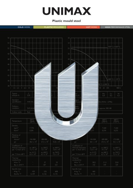
<strong>UNIMAX</strong><br />
Plastic mould steel
<strong>UNIMAX</strong><br />
General<br />
Unimax is a chromium-molybdenum-vanadium<br />
alloyed tool steel which is characterized by:<br />
• Excellent toughness and ductility in all<br />
directions<br />
• Good wear resistance<br />
• Good dimensional stability at heat treatment and<br />
in service<br />
• Excellent through-hardening properties<br />
• Good resistance to tempering back<br />
• Good hot strength<br />
• Good thermal fatigue resistance<br />
• Excellent polishability<br />
Typical C Si Mn Cr Mo V<br />
analysis % 0,5 0,2 0,5 5,0 2,3 0,5<br />
Standard<br />
specification None<br />
Delivery<br />
condition<br />
Soft annealed to approx. 185 HB<br />
Colour code Brown/grey<br />
Applications<br />
Unimax is suitable for long run production moulds,<br />
moulds for reinforced plastics and compression<br />
moulding.<br />
Unimax is a problem solver in severe cold work<br />
tooling applications such as heavy duty blanking,<br />
cold forging and thread rolling, where high<br />
chipping resistance is required.<br />
Engineering and hot work applications requiring<br />
high hardness and toughness are also an option.<br />
Properties<br />
The properties below are representative of samples<br />
which have been taken from the centre of bars with<br />
dimensions 396 x 136 mm (15,6"x 5,35"), Ø 125<br />
mm (4,93") and Ø 220 mm (8,67"). Unless otherwise<br />
indicated all specimens have been hardened at<br />
1025°C (1875°F), gas quenched in a vacuum<br />
furnace and tempered twice at 525°C (975°F) for<br />
two hours; yielding a working hardness of 56–<br />
58 HRC.<br />
PHYSICAL PROPERTIES<br />
Hardened and tempered to 56–58 HRC<br />
Temperature 20°C 200°C 400°C<br />
(68°F) (390°F) (750°F)<br />
Density,<br />
kg/m 3 7 790 – –<br />
lbs/in 3 0,281<br />
Modulus of elasticity<br />
MPa 213 000 192 000 180 000<br />
psi 31,2 x 10 6 27,8 x 10 6 26,1 x 10 6<br />
Coefficient of<br />
thermal expansion<br />
per °C from 20°C – 11,5 x 10 –6 12,3 x 10 –6<br />
per °F from 68°F – 6,3 x 10 –6 6,8 x 10 –6<br />
Thermal<br />
conductivity<br />
W/m °C – 25 28<br />
Btu in/(ft 2 h°F) – 174 195<br />
Specific heat<br />
j/kg°C 460 – –<br />
Btu/lb°F 0,11<br />
MECHANICAL PROPERTIES<br />
Approx. strength and ductility at room temperature<br />
at tensile testing.<br />
Hardness 53 HRC 56 HRC 58 HRC<br />
Yield<br />
strength, Rp0,2 1285 MPa 1437 MPa 1748 MPa<br />
Tensile<br />
strength, Rm 1533 MPa 1739 MPa 2285 MPa<br />
Elongation, A 5 10 % 10 % 8 %<br />
Reduction<br />
of area, Z 56 % 58 % 28 %<br />
This information is based on our present state of knowledge and is<br />
intended to provide general notes on our products and their uses. It should<br />
not therefore be construed as a warranty of specific properties of the<br />
products described or a warranty for fitness for a particular purpose.<br />
2
<strong>UNIMAX</strong><br />
Approximate strength at elevated temperatures<br />
Longitudinal direction.<br />
The specimens were hardened from 1025°C<br />
(1875°F) and tempered twice at 525°C (975°F) to<br />
58 HRC.<br />
Stress, MPa<br />
2400<br />
2200<br />
2000<br />
1800<br />
1600<br />
1400<br />
1200<br />
1000<br />
800<br />
100 200 300 400 500 600°C<br />
210 390 570 750 930 1110°F<br />
Testing temperature<br />
Effect of time at high temperatures on hardness<br />
Initial hardness 57 HRC.<br />
IHardness HRC<br />
60<br />
55<br />
50<br />
45<br />
40<br />
35<br />
30<br />
25<br />
20<br />
Rm<br />
Rp0,2<br />
600°C (1110°F)<br />
650°C (1200°F)<br />
550°C (1020°F)<br />
1 10 100<br />
Time, h<br />
Effect of testing temperature on impact energy<br />
Charpy-V specimens, longitudinal and short transverse<br />
direction. Approximate values for specimens<br />
from Ø125 mm (4,9") bar.<br />
Heat treatment—<br />
general recommendations<br />
SOFT ANNEALING<br />
Protect the steel and heat through to 850°C<br />
(1560°F). Then cool in furnace at 10°C (20°F) per<br />
hour to 600°C (1110°F), then freely in air.<br />
STRESS RELIEVING<br />
After rough machining the tool should be heated<br />
through to 650°C (1200°F), holding time 2 hours.<br />
Cool slowly to 500°C (930°F), then freely in air.<br />
HARDENING<br />
Preheating temperature: 600–650°C (1110–1200°F)<br />
and 850–900°C (1560–1650°F).<br />
Austenitizing temperature: 1000–1025°C (1830–<br />
1875°F), normally 1025°C (1875°F).<br />
Holding time: 30 minutes<br />
Temperature Soaking time Hardness before<br />
°C °F minutes tempering<br />
1000 1830 30 61 HRC<br />
1025 1875 30 63 HRC<br />
Soaking time = time at hardening temperature after the tool is<br />
fully heated through.<br />
Protect the tool against decarburization and<br />
oxidation during austenitizing.<br />
QUENCHING MEDIA<br />
• High speed gas/circulating atmosphere.<br />
•Vacuum furnace (high speed gas with sufficient<br />
overpressure).<br />
• Martempering bath, salt bath or fluidized bed at<br />
500–550°C (930–1020°F).<br />
• Martempering bath at 200–350°C (390–660°F).<br />
Note: Temper the tool as soon as its temperature<br />
reaches 50–70°C (120–160°F).<br />
Impact energy, KV (J)<br />
35<br />
30<br />
25<br />
20<br />
15<br />
Longitudinal<br />
Short transverse<br />
10<br />
5<br />
0<br />
–100 0 100 200 300 400 °C<br />
–212 32 212 392 572 752 °F<br />
Testing temperature<br />
3
<strong>UNIMAX</strong><br />
CCT graph—Austenitizing temperature 1025°C (1875°F). Holding time 30 minutes.<br />
°F<br />
2000<br />
1800<br />
1600<br />
1400<br />
1200<br />
1000<br />
800<br />
600<br />
°C<br />
1100<br />
1000<br />
900<br />
800<br />
700<br />
600<br />
500<br />
400<br />
300<br />
Austenitizing temperature 1025°C (1875°F)<br />
Holding time 30 min<br />
Carbides<br />
Pearlite<br />
Bainite<br />
A cf<br />
= 890°C (1630°F)<br />
A c s<br />
= 820°C<br />
Cooling<br />
Curve No.<br />
(1505°F)<br />
1<br />
2<br />
3<br />
4<br />
5<br />
6<br />
Hardness<br />
HV 10<br />
835<br />
819<br />
798<br />
782<br />
724<br />
712<br />
T<br />
800–500<br />
(sec)<br />
1<br />
5<br />
33<br />
140<br />
630<br />
1064<br />
400<br />
200<br />
200<br />
100<br />
M s<br />
Martensite<br />
M f<br />
1 2 3 4 5 6 7 8<br />
9<br />
7<br />
8<br />
9<br />
674<br />
525<br />
476<br />
2900<br />
6250<br />
13850<br />
1 10 100 1 000 10 000 100 000 Seconds<br />
1 10 100 1 000 Minutes<br />
1 10 100 Hours<br />
0.2 1.5 10 90 600<br />
Air cooling of<br />
bars, Ø mm<br />
Hardness, grain size and retained austenite as<br />
functions of austenitizing temperature<br />
Grain<br />
size<br />
ASTM Hardness, HRC<br />
25 65<br />
20<br />
15<br />
64<br />
63<br />
62<br />
61<br />
Hardness<br />
Retained austenite<br />
Grain size<br />
Retained austenite %<br />
25<br />
60<br />
990 1000 1010 1020 1030 1040 1050 °C<br />
1815 1830 1850 1870 1885 1905 1920 °F<br />
Austenitizing temperature T A , 30 minutes<br />
20<br />
15<br />
10<br />
5<br />
TEMPERING<br />
Choose the tempering temperature according to the<br />
hardness required by reference to the tempering<br />
graph below. Temper at least twice with intermittent<br />
cooling to room temperature. The lowest<br />
tempering temperature which should be used is<br />
525°C (980°F). The minimum holding time at<br />
temperature is 2 hours.<br />
Tempering graph<br />
Hardness, HRC<br />
60<br />
58<br />
56<br />
T A= 1025°C (1875°F) Hardness<br />
Retained austenite, %<br />
35<br />
30<br />
25<br />
54<br />
52<br />
T A= 1000°C (1830°F) Hardness<br />
20<br />
15<br />
50<br />
10<br />
48<br />
5<br />
T A= 1025°C (1875°F) Retained austenite<br />
46<br />
500 520 540 560 580 600°C<br />
932 968 1004 1040 1076 1112°F<br />
Tempering temperature (2 x 2h)<br />
4
<strong>UNIMAX</strong><br />
DIMENSIONAL CHANGES<br />
DURING HARDENING AND TEMPERING<br />
The dimensional changes have been measured after<br />
austenitizing at 1020°C (1870°F)/30 minutes<br />
followed by gas quenching in N 2 at a cooling rate of<br />
1,1°C/second between 800–500°C (1470–930°F) in<br />
a cold chamber vacuum furnace.<br />
Specimen size: 100 x 100 x 100 mm (3,9"x 3,9"x<br />
3,9")<br />
Dimensional changes, %<br />
0,16<br />
0,12<br />
0,08<br />
0,04<br />
1020°C Transverse<br />
0,00<br />
1020°C Short transverse<br />
1020°C Longitudinal<br />
–0,04<br />
500 520 540 560 580 600°C<br />
932 968 1004 1040 1076 1112°F<br />
Tempering temperature (2 x 2h)<br />
Surface treatments<br />
Tool steels may be given a surface treatment in<br />
order to reduce friction and increase wear resistance.<br />
The most commonly used treatments are<br />
nitriding and surface coating with wear resistant<br />
layers produced via PVD or CVD.<br />
The high hardness and toughness together with a<br />
good dimensional stability makes Unimax suitable<br />
as a substrate steel for various surface coatings.<br />
NITRIDING AND NITROCARBURIZING<br />
Nitriding and nitrocarburizing result in a hard<br />
surface layer which is very resistant to wear and<br />
galling.<br />
The surface hardness after nitriding is approximately<br />
1000–1200 HV 0,2kg . The thickness of the layer<br />
should be chosen to suit the application in question.<br />
PVD<br />
Physical vapour deposition, PVD, is a method for<br />
applying wear-resistant surface coating at temperatures<br />
between 200–500°C (390–930°F).<br />
Cutting data<br />
recommendations<br />
The cutting data below are to be considered as<br />
guiding values which must be adapted to existing<br />
local conditions.<br />
Condition: Soft annealed to ~185 HB<br />
TURNING<br />
Turning with<br />
Turning<br />
carbide<br />
with high<br />
Cutting data<br />
speed steel<br />
parameters Rough turning Fine turning Fine turning<br />
Cutting<br />
speed (v c )<br />
m/min 150–200 200–250 15–20<br />
f.p.m. 490–655 655–820 50–65<br />
Feed (f)<br />
mm/r 0,2–0,4 0,05–0,2 0,05–0,3<br />
i.p.r. 0,008–0,016 0,002–0,008 0,002–0,012<br />
Depth<br />
of cut (a p )<br />
mm 2–4 0,5–2 0,5–2<br />
inch 0,08–0,16 0,02–0,08 0,02–0,08<br />
Carbide<br />
designation<br />
ISO P20–P30 P10 –<br />
US C6–C5 C7 –<br />
Coated carbide Coated carbide<br />
or cermet<br />
MILLING<br />
Face- and square shoulder milling<br />
Milling with carbide<br />
Cutting data<br />
parameters Rough milling Fine milling<br />
Cutting speed (v c )<br />
m/min 120–170 170–210<br />
f.p.m. 394–558 558–690<br />
Feed (f z )<br />
mm/tooth 0,2–0,4 0,1–0,2<br />
inch/tooth 0,008–0,016 0,004–0,008<br />
Depth of cut (a p )<br />
mm 2–4 0,5–2<br />
inch 0,08–0,16 0,02–0,08<br />
Carbide designation<br />
ISO P20–P40 P10<br />
US C6–C5 C7<br />
Coated carbide Coated<br />
carbide<br />
or cermet<br />
CVD<br />
Chemical vapour deposition, CVD, is a method for<br />
applying wear-resistant surface coating at a temperature<br />
of around 1000°C (1830°F).<br />
5
<strong>UNIMAX</strong><br />
End milling<br />
Type of milling<br />
Carbide<br />
Cutting data Solid indexable High<br />
parameters carbide insert speed steel<br />
Cutting<br />
speed (v c )<br />
m/min 120–150 110–150 20–25 1)<br />
f.p.m. 390–490 360–490 66–80 1)<br />
Feed (f z )<br />
mm/tooth 0,01–0,20 2) 0,06–0,20 2) 0,01–0,30 2)<br />
inch/tooth 0,0003–0,008 2) 0,002–0,008 2) 0,0003–0,012 2)<br />
Carbide<br />
designation<br />
ISO – P20–P30 –<br />
US C6–C5 –<br />
1)<br />
For coated HSS end mill v c 35–40 m/min. (115 –130 f.p.m.).<br />
2)<br />
Depending on radial depth of cut and cutter diameter.<br />
Electrical Discharge<br />
Machining<br />
Following the EDM process, the applicable die<br />
surfaces are covered with a resolidified layer (white<br />
layer) and a rehardened and untempered layer, both<br />
of which are very brittle and hence detrimental to<br />
die performance.<br />
If EDM is used the white layer must be completely<br />
removed mechanically by grinding or stoning.<br />
After finish-machining the tool should be given an<br />
additional temper at approx. 25°C (50°F) below the<br />
highest previous tempering temperature.<br />
Further information is given in the <strong>Uddeholm</strong><br />
brochure “EDM of Tool Steel”.<br />
DRILLING<br />
High speed steel twist drill<br />
Drill diameter Cutting Feed (f)<br />
speed (v c )<br />
mm inch m/min f.p.m. mm/r i.p.r.<br />
– 5 –3/16 15–20* 49–66* 0,05–0,10 0,002–0,004<br />
5–10 3/16–3/8 15–20* 49–66* 0,10–0,20 0,004–0,008<br />
10–15 3/8–5/8 15–20* 49–66* 0,20–0,30 0,008–0,012<br />
15–20 5/8–3/4 15–20* 49–66* 0,30–0,35 0,012–0,014<br />
1)<br />
For coated HSS drill v c ~35–40 m/min. (115–130 f.p.m.).<br />
Carbide drill<br />
Type of drill<br />
Cutting data Indexable Solid Brazed<br />
parameters insert carbide carbide 1)<br />
Cutting<br />
speed (v c )<br />
m/min 180–220 120–150 60–90<br />
f.p.m. 590–720 390–490 195–295<br />
Feed (f)<br />
mm/r 0,03–0,10 2) 0,10–0,25 2) 0,15–0,25 2)<br />
i.p.r. 0,001–0,004 2) 0,004–0,01 2) 0,006–0,01 2)<br />
1)<br />
Drill with internal cooling channels and brazed carbide tip.<br />
2)<br />
Depending on drill diameter.<br />
GRINDING<br />
A general grinding wheel recommendation is given<br />
below. More information can be found in the<br />
<strong>Uddeholm</strong> publication “Grinding of Tool Steel”.<br />
Welding<br />
Welding of die components can be performed, with<br />
acceptable results, as long as the proper precautions<br />
are taken during the preparation of the joint, the<br />
filler material selection, the preheating of the die,<br />
the controlled cooling of the die and the post weld<br />
heat treatment processes. The following guidelines<br />
summarize the most important welding process<br />
parameters.<br />
For more detailed information refer to <strong>Uddeholm</strong>’s<br />
“Welding of Tool Steel” brochure.<br />
Welding method TIG MMA<br />
Preheating 200–250°C 200–250°C<br />
temperature (390–480°F) (390–480°F)<br />
Filler material UTP ADUR600 UTP 67S<br />
UTP A73G2 UTP 73G2<br />
Maximum<br />
interpass 350°C 350°C<br />
temperature (660°F) (660°F)<br />
Post weld cooling 20–40°C/h (45–70°F/h) for the first<br />
two hours and then freely in air.<br />
Hardness<br />
after welding 54–60 HRC 55–58 HRC<br />
Post weld heat treatment<br />
Hardened<br />
condition Temper at 510°C (950°F) for 2 h.<br />
Soft annealed Soft-anneal according to the “Heat<br />
condition<br />
treatment recommendations”.<br />
Recommeded grinding wheels<br />
Soft annealed Hardened<br />
Type of grinding condition condition<br />
Face grinding<br />
straight wheel A 46 HV A 46 GV<br />
Face grinding<br />
segments A 24 GV A 36 GV<br />
Cylindrical grinding A 46 LV A 60 KV<br />
Internal grinding A 46 JV A 60 IV<br />
Profile grinding A 100 LV A 120 KV<br />
Further information<br />
Please contact your local <strong>Uddeholm</strong> office for<br />
further information on the selection, heat treatment,<br />
application and availability of <strong>Uddeholm</strong> tool steels.<br />
6