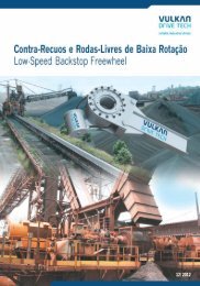
Capa Contra Recuo Ingles
Capa Contra Recuo Ingles
Capa Contra Recuo Ingles
Create successful ePaper yourself
Turn your PDF publications into a flip-book with our unique Google optimized e-Paper software.
FUNCTIONING<br />
Freewheel functions<br />
Freewheels are power transmission<br />
components with particular<br />
characteristics:<br />
-- In one direction of rotation there is no<br />
transmission between the inner and outer<br />
rings; the freewheel is in freewheeling<br />
operation.<br />
- In the other direction of rotation there is<br />
transmission between the inner and<br />
outer rings; in this direction it is possible<br />
to transmit high torque.<br />
These features allow freewheels to perform<br />
various functions completely automatically<br />
in the most diverse machines. No<br />
mechanical or hydraulic operating<br />
equipment is required to command them,<br />
such as in brakes and clutches.<br />
Freewheels are used as:<br />
- indexing freewheels (advance)<br />
- overrunning clutches<br />
- backstops<br />
RINGSPANN freewheels are an<br />
indispensable design element in the<br />
automobile and machine industries, as<br />
well as in aerospace technology. The<br />
freewheel, as an automatic driving<br />
element, is preferred to conventional<br />
solutions because it offers significant<br />
advantages, such as:<br />
- operating safety<br />
- economy<br />
- a high degree of automation<br />
In no way do such advantages increase<br />
costs; on the contrary, applying<br />
freewheels reduces costs compared to<br />
alternatives that involve couplings or<br />
commanded brakes, since in the case of<br />
freewheels, there is no additional costs<br />
related to these commands. For some<br />
equipment, applying the freewheel is<br />
the only economically feasible solution.<br />
As example, we cite automatic vehicle<br />
transmission with hydrodynamic torque<br />
converter coupled to a planetary gear<br />
reducer. In this catalogue, we present<br />
freewheels for exclusive application,<br />
such as backstops. For other<br />
application types, please consult us.<br />
Free<br />
Locked<br />
outer<br />
ring<br />
inner<br />
ring<br />
Core<br />
(rollers or sprags)<br />
We reserve the right to make changes without prior notice<br />
01
APPLICATION AS BACKSTOP<br />
RINGSPANN freewheels are used to<br />
prevent reverse rotation of the operating<br />
direction. Due to functional and safety<br />
issues, many equipment must work in just<br />
one specified direction of rotation.<br />
To exemplify, there are regulations<br />
preventing the application of mechanical<br />
safety devices in conveyor systems. In<br />
pumping equipments, a reverse rotation<br />
(due to the backflow caused by the<br />
opposite pressure of the pumped fluid)<br />
must be avoided at all costs, otherwise,<br />
the pump working as a turbine will cause<br />
a high rotation of the motor pump<br />
assembly, resulting in damages to both.<br />
In this case as also in others cases, as<br />
shown in this catalogue, automatic<br />
blocking by the backstop is guaranteed<br />
since it operates as an automatic driving<br />
element. When the equipment is in<br />
normal operation, the backstop will be<br />
turning freely; the torque (blocking) will be<br />
transmitted when the rotation speed is<br />
equal to zero. The automatic and<br />
immediate locking action, free of shock,<br />
guarantees the necessary operating<br />
safety.<br />
Inclined conveyors<br />
Elevators<br />
Gear units<br />
Electric motors<br />
Gear motors<br />
The backstop prevents reverse rotation of<br />
the conveyor belt or elevator in case of a<br />
power failure or when the motor is turned<br />
off.<br />
Fans<br />
Ventilators<br />
The backstop prevents reverse rotation in<br />
case of fluid backflow.<br />
Pumps<br />
Compressors<br />
The backstop prevents reverse drive of<br />
the equipment.<br />
02<br />
We reserve the right to make changes without prior notice
SELECTION<br />
Sprag lift-off X<br />
Sprags with tilted blocking by<br />
centrifugal force<br />
Tilting by action of the centrifugal force (liftoff<br />
X patented in Germany and other<br />
countries) is used in backstops when the<br />
inner ring (connected to the axle) turns<br />
freely and in high rotation. In this condition,<br />
centrifugal force Fc acting on the sprag<br />
causes its tilting so as to distance it from<br />
the inner track of the outer ring, promoting<br />
a frictionless operation consequently<br />
without wear or energy dissipation.<br />
The figure on the right shows a<br />
RINGSPANN freewheel with lift-off X<br />
turning freely. The sprags and cage<br />
containing them turn together with the<br />
inner ring. The centrifugal force Fc tilted<br />
the sprags counterclockwise, until the<br />
sprags are collected in the support ring. A<br />
gap was thus created between the sprags<br />
and outer track. The freewheel is<br />
operating without any friction.<br />
When the rotation of the inner ring<br />
sufficiently reduces the intensity of the<br />
centrifugal force to a value less than the<br />
force of the springs, the sprags return to<br />
Anel externo<br />
Gaiola<br />
Anel interno<br />
a<br />
n<br />
the position of contact with the outer track<br />
and the freewheel is again ready for the<br />
locking function.<br />
Fc<br />
Sustentação<br />
Corpo de bloqueio<br />
C G<br />
03<br />
Selecting the backstop size<br />
The stop of an inclined conveyor belt or<br />
loaded elevator, for example, of a pump,<br />
is a highly dynamic process during which<br />
there are torque peaks. These torque<br />
peaks are determinant factors in<br />
selecting the backstop size.<br />
The most reliable method to predict<br />
torques acting during the instant of<br />
locking action involves oscillatory<br />
calculation of the complete system, which<br />
requires knowledge of parameters like:<br />
rotating masses, rigidity of components,<br />
etc. Therefore, in most practical cases,<br />
oscillatory calculation is not viable. As<br />
alternative, we use the traditional and<br />
reliable method to determine the<br />
selection torque M A, as shown below:<br />
M A = 1,75 . . ML<br />
In many cases, only the nominal power of<br />
the motor Po (KW) is known. In this case,<br />
apply the following calculation:<br />
M<br />
= 1,75 . 9550 . <br />
2<br />
A . P o/ nsp<br />
where:<br />
M A =Bending moment to select<br />
backstop (Nm).<br />
M L = 9550 . P L/ n sp= Bending moment of<br />
the load or static bending moment<br />
of load reverse reflected on the<br />
backstop axle (Nm).<br />
P L = Conveyor lifting power at full load<br />
(kW), resulting from the lifting<br />
height (m) multiplied by the load to<br />
be transported per second (kN/s).<br />
P o = Nominal power of the motor (kW)<br />
n sp = Rotations per minute of the axle on<br />
which the backstop will be applied.<br />
= Yield of the installation<br />
lifting power<br />
lifting power + power loss<br />
After calculating MA, the backstop size is<br />
selected according to this catalogue's<br />
tables to meet the following condition:<br />
MN MA<br />
M N = Nominal bending moment of the<br />
backstop [Nm] according to this<br />
catalogue's tables.<br />
Approximate values of :<br />
Installation type<br />
Conveyor belt,<br />
inclined up to 6º<br />
Conveyor belt,<br />
inclined up to 8º<br />
Conveyor belt,<br />
inclined up to 10º<br />
Conveyor belt,<br />
inclined up to 12º<br />
Conveyor belt,<br />
inclined up to 15º<br />
Fuse pumps<br />
Ball mills,<br />
rotary kilns<br />
Cup conveyor,<br />
elevators<br />
Hammer mill<br />
In case of doubts, consult us or send us<br />
the questionnaire contained in this<br />
dialogue.<br />
<br />
0,71<br />
0,78<br />
0,83<br />
0,86<br />
0,89<br />
0,93<br />
0,85<br />
0,92<br />
0,93<br />
2<br />
0,50<br />
0,61<br />
0,69<br />
0,74<br />
0,79<br />
0,87<br />
0,72<br />
0,85<br />
0,87<br />
We reserve the right to make changes without prior notice
TYPES<br />
Backstops without bearing support<br />
Backstops as machine design elements<br />
integrated to gear units, electric motors,<br />
pumps, etc. These backstops, due to<br />
lacking bearing support, should be<br />
assembled in order to guarantee<br />
concentricity between the outer and inner<br />
rings (hub).<br />
The use of core with sprags tilted by the<br />
centrifugal force waives the need for<br />
lubrication. They operate free of<br />
maintenance.<br />
Backstops with incorporated<br />
bearings and bending arm<br />
Encapsulated backstops with bearing<br />
support and inner lubrication enable<br />
connection to gear units, conveyors,<br />
elevators and fans, etc. independently. It<br />
is possible to turn the axle in both rotation<br />
directions, releasing the bending arm of<br />
the structure. The reaction to the blocking<br />
bending moment occurs through the<br />
bending arm anchored in the equipment<br />
structure.<br />
04<br />
We reserve the right to make changes without prior notice
FXM PROFILE<br />
Backstops for high bending moments and high rotations with sprag lift-off X<br />
FXM<br />
FXM<br />
FXM<br />
FXM<br />
FXM<br />
FXM<br />
FXM<br />
FXM<br />
FXM<br />
FXM<br />
FXM<br />
FXM<br />
FXM<br />
FXM<br />
FXM<br />
FXM<br />
FXM<br />
FXM<br />
FXM<br />
FXM<br />
FXM<br />
FXM<br />
FXM<br />
FXM<br />
FXM<br />
FXM<br />
FXM<br />
Type<br />
Size<br />
31<br />
38<br />
46<br />
51<br />
56<br />
61<br />
66<br />
76<br />
86<br />
101<br />
85<br />
100<br />
120<br />
140<br />
170<br />
200<br />
240<br />
240<br />
260<br />
290<br />
290<br />
310<br />
310<br />
320<br />
360<br />
410<br />
2.410<br />
- 17 DX<br />
- 17 DX<br />
- 25 DX<br />
- 25 DX<br />
- 25 DX<br />
- 19 DX<br />
- 25 DX<br />
- 25 DX<br />
- 25 DX<br />
- 25 DX<br />
- 40 SX<br />
- 40 SX<br />
- 50 SX<br />
- 50 SX<br />
- 63 SX<br />
- 63 SX<br />
- 63 UX<br />
- 96 UX<br />
- 63 UX<br />
- 70 UX<br />
- 96 UX<br />
- 70 UX<br />
- 96 UX<br />
- 70 UX<br />
- 100 UX<br />
- 100 UX<br />
- 100 UX<br />
Theoretica<br />
l bending<br />
moment<br />
Features:<br />
Robust, high-performance backstop. The<br />
capacity to operate with high radial run<br />
outs enables application, without<br />
problem, even in axles supported on<br />
conical roller bearings or slide bearings.<br />
Min.<br />
rotation<br />
Max.<br />
Rotation<br />
(radial runout)<br />
(Tilting)<br />
0 A<br />
0,1 A<br />
0,2 A<br />
0,3 A<br />
0,4 A<br />
0,5 A<br />
0,8 A<br />
Nm Nm Nm Nm Nm Nm Nm rpm rpm<br />
100<br />
150<br />
390<br />
480<br />
580<br />
420<br />
800<br />
1050<br />
1350<br />
1700<br />
1900<br />
2700<br />
6500<br />
8700<br />
20000<br />
26000<br />
31000<br />
52050<br />
38500<br />
59500<br />
91000<br />
69000<br />
107000<br />
76500<br />
149000<br />
193000<br />
364000<br />
100<br />
140<br />
380<br />
470<br />
570<br />
410<br />
780<br />
1040<br />
1300<br />
1600<br />
1900<br />
2600<br />
6300<br />
8500<br />
19000<br />
23000<br />
30500<br />
51000<br />
38000<br />
59000<br />
90000<br />
68000<br />
105000<br />
73000<br />
139500<br />
179500<br />
350000<br />
Bending moment in function of concentricity<br />
95<br />
130<br />
350<br />
420<br />
490<br />
370<br />
700<br />
890<br />
1030<br />
1400<br />
1800<br />
2500<br />
5800<br />
7900<br />
16000<br />
20500<br />
30000<br />
49000<br />
37000<br />
56000<br />
82500<br />
64500<br />
99000<br />
67000<br />
128000<br />
167000<br />
315000<br />
-<br />
-<br />
-<br />
-<br />
-<br />
-<br />
-<br />
-<br />
-<br />
-<br />
1800<br />
2400<br />
4800<br />
6700<br />
14000<br />
17500<br />
29000<br />
47500<br />
36500<br />
50000<br />
77500<br />
60000<br />
85500<br />
62000<br />
119500<br />
154500<br />
296500<br />
-<br />
-<br />
-<br />
-<br />
-<br />
-<br />
-<br />
-<br />
-<br />
-<br />
1700<br />
2200<br />
4400<br />
5500<br />
13000<br />
15500<br />
26000<br />
46000<br />
33000<br />
47000<br />
70000<br />
55000<br />
81000<br />
56500<br />
103500<br />
137000<br />
277500<br />
-<br />
-<br />
-<br />
-<br />
-<br />
-<br />
-<br />
-<br />
-<br />
-<br />
1600<br />
2000<br />
3600<br />
5400<br />
12000<br />
14000<br />
24000<br />
44000<br />
29000<br />
45000<br />
62500<br />
49000<br />
74000<br />
49500<br />
90000<br />
121500<br />
266000<br />
-<br />
-<br />
-<br />
-<br />
-<br />
-<br />
-<br />
-<br />
-<br />
-<br />
-<br />
-<br />
-<br />
-<br />
-<br />
-<br />
19500<br />
35000<br />
25000<br />
37000<br />
55000<br />
43000<br />
68000<br />
43000<br />
80500<br />
111500<br />
223500<br />
The bending moments informed are nominal and contain a service factor 2. The theoretical bending moment presumes perfect concentricity between inner and outer rings. In practice, the concentricity is<br />
affected by the gaps of the bearings and machining deviations of the adjacent parts. For this reason, the nominal bending moments of the table consider the radial runout present. For higher rotations, please<br />
consult us. The sizes and holes marked with (*) are preferential in Vulkan do Brasil's supply program.<br />
Sprags with centrifugal tilting assure long<br />
lastingness. It does not require special<br />
lubrication when operating above the<br />
centrifugal tilting. The thin film of lubricant<br />
applied during the assembly is enough for<br />
890<br />
860<br />
820<br />
750<br />
730<br />
750<br />
700<br />
670<br />
630<br />
610<br />
430<br />
400<br />
320<br />
320<br />
250<br />
240<br />
220<br />
220<br />
210<br />
200<br />
200<br />
195<br />
195<br />
195<br />
180<br />
170<br />
210<br />
5000<br />
5000<br />
5000<br />
5000<br />
5000<br />
5000<br />
5000<br />
5000<br />
5000<br />
5000<br />
6000<br />
4500<br />
4000<br />
3000<br />
2700<br />
2100<br />
3000<br />
2500<br />
2500<br />
2500<br />
2500<br />
2500<br />
2100<br />
2000<br />
1800<br />
1500<br />
1500<br />
the operation (see page 7). This backstop<br />
does not need maintenance. The<br />
transmissible torque capacity depends<br />
on the concentricity between the inner<br />
and outer rings of the backstop.<br />
We reserve the right to make changes without prior notice<br />
05
FXM PROFILE<br />
Backstops for high bending moments and high rotations with sprag lift-off X<br />
Tolerance for Ø F**<br />
Type<br />
Min.2<br />
B<br />
A<br />
V<br />
W<br />
0 for + 0,02 mm<br />
DX<br />
0 for + 0,05 mm<br />
0 for + 0,05 mm<br />
SX<br />
UX<br />
Px30º<br />
A<br />
A<br />
U<br />
ØD<br />
ØT<br />
ØE<br />
Ød H7<br />
ØJ<br />
ØF**<br />
ØD<br />
ØT<br />
L<br />
Z = number of fastening holes for G<br />
bolts in circumference T<br />
Type<br />
Size<br />
Hole d<br />
A<br />
B D E F G J L P T U V W Z<br />
Min.<br />
06<br />
FXM<br />
FXM<br />
FXM<br />
FXM<br />
FXM<br />
FXM<br />
FXM<br />
FXM<br />
FXM<br />
FXM<br />
FXM<br />
FXM<br />
FXM<br />
FXM<br />
FXM<br />
FXM<br />
FXM<br />
FXM<br />
FXM<br />
FXM<br />
FXM<br />
FXM<br />
FXM<br />
FXM<br />
FXM<br />
FXM<br />
FXM<br />
31<br />
38<br />
46<br />
51<br />
56<br />
61<br />
66<br />
76<br />
86<br />
101<br />
85<br />
100<br />
120<br />
140<br />
170<br />
200<br />
240<br />
240<br />
260<br />
290<br />
290<br />
310<br />
310<br />
320<br />
360<br />
410<br />
2.410<br />
- 17 DX<br />
- 17 DX<br />
- 25 DX<br />
- 25 DX<br />
- 25 DX<br />
- 19 DX<br />
- 25 DX<br />
- 25 DX<br />
- 25 DX<br />
- 25 DX<br />
- 40 SX<br />
- 40 SX<br />
- 50 SX<br />
- 50 SX<br />
- 63 SX<br />
- 63 SX<br />
- 63 UX<br />
- 96 UX<br />
- 63 UX<br />
- 70 UX<br />
- 96 UX<br />
- 70 UX<br />
- 96 UX<br />
- 70 UX<br />
- 100 UX<br />
- 100 UX<br />
- 100 UX<br />
20<br />
25<br />
25<br />
25<br />
35<br />
30<br />
35<br />
45<br />
40<br />
55<br />
45<br />
45<br />
60<br />
65<br />
70<br />
130<br />
-<br />
-<br />
-<br />
-<br />
-<br />
-<br />
-<br />
-<br />
-<br />
-<br />
-<br />
-<br />
-<br />
-<br />
30<br />
-<br />
35<br />
40<br />
55<br />
45<br />
70<br />
50<br />
50<br />
65<br />
90<br />
85<br />
-<br />
-<br />
-<br />
-<br />
-<br />
-<br />
-<br />
-<br />
-<br />
-<br />
-<br />
-<br />
-<br />
-<br />
-<br />
35<br />
-<br />
40<br />
45<br />
-<br />
50<br />
-<br />
60<br />
55<br />
70<br />
95<br />
100<br />
100<br />
-<br />
-<br />
-<br />
-<br />
-<br />
-<br />
-<br />
-<br />
-<br />
-<br />
-<br />
Std<br />
mm<br />
-<br />
-<br />
-<br />
-<br />
-<br />
-<br />
-<br />
-<br />
60<br />
-<br />
65<br />
60<br />
75<br />
100<br />
120<br />
-<br />
-<br />
-<br />
-<br />
-<br />
-<br />
-<br />
-<br />
-<br />
-<br />
-<br />
-<br />
Scope of supply<br />
The cover, shown in the figure above, is<br />
supplied optionally upon request. please<br />
indicate separately in the order.<br />
-<br />
-<br />
-<br />
-<br />
-<br />
-<br />
-<br />
-<br />
65<br />
-<br />
-<br />
70<br />
80<br />
110<br />
-<br />
-<br />
-<br />
-<br />
-<br />
-<br />
-<br />
-<br />
-<br />
-<br />
-<br />
-<br />
-<br />
-<br />
-<br />
-<br />
-<br />
-<br />
-<br />
-<br />
-<br />
-<br />
-<br />
-<br />
75<br />
95<br />
-<br />
-<br />
-<br />
-<br />
-<br />
-<br />
-<br />
-<br />
-<br />
-<br />
-<br />
-<br />
-<br />
-<br />
Max.<br />
mm<br />
20<br />
25<br />
30<br />
36<br />
40<br />
45<br />
48<br />
55<br />
70<br />
75<br />
65<br />
75<br />
95<br />
110<br />
130<br />
155<br />
185<br />
185<br />
205<br />
230<br />
230<br />
240<br />
240<br />
250<br />
280<br />
320<br />
320<br />
mm mm mm mm mm mm mm mm mm mm mm mm<br />
17<br />
17<br />
25<br />
25<br />
25<br />
19<br />
25<br />
25<br />
25<br />
25<br />
40<br />
40<br />
50<br />
50<br />
63<br />
63<br />
63<br />
96<br />
63<br />
70<br />
96<br />
70<br />
96<br />
70<br />
100<br />
100<br />
200<br />
25<br />
25<br />
35<br />
35<br />
35<br />
27<br />
35<br />
35<br />
40<br />
50<br />
50<br />
50<br />
60<br />
70<br />
80<br />
80<br />
80<br />
125<br />
80<br />
80<br />
110<br />
125<br />
125<br />
80<br />
120<br />
120<br />
220<br />
Keyways according to DIN 6885/1. The holes marked with (*) have key according to DIN 6885/3. Keyway width tolerance according to IT 10. The sizes and holes marked with (*) are preferential in Vulkan do<br />
Brasil's supply program.<br />
85<br />
90<br />
95<br />
105<br />
110<br />
120<br />
132<br />
140<br />
150<br />
175<br />
175<br />
190<br />
210<br />
245<br />
290<br />
310<br />
400<br />
420<br />
430<br />
460<br />
460<br />
497<br />
497<br />
490<br />
540<br />
630<br />
630<br />
41<br />
48<br />
56<br />
62<br />
66<br />
74<br />
78<br />
90<br />
100<br />
116<br />
100<br />
116<br />
140<br />
162<br />
193<br />
225<br />
280<br />
280<br />
300<br />
330<br />
330<br />
360<br />
360<br />
360<br />
400<br />
460<br />
460<br />
55<br />
62<br />
70<br />
75<br />
80<br />
85<br />
90<br />
100<br />
110<br />
125<br />
125<br />
140<br />
160<br />
180<br />
210<br />
240<br />
310<br />
310<br />
330<br />
360<br />
360<br />
380<br />
380<br />
390<br />
430<br />
480<br />
480<br />
M6<br />
M6<br />
M6<br />
M6<br />
M6<br />
M8<br />
M8<br />
M8<br />
M8<br />
M10<br />
M10<br />
M10<br />
M10<br />
M12<br />
M16<br />
M16<br />
M20<br />
M24<br />
M20<br />
M20<br />
M20<br />
M20<br />
M20<br />
M24<br />
M24<br />
M24<br />
M30<br />
Installation cares<br />
The backstop does not have inner<br />
bearings. Therefore, the outer ring<br />
should be mounted concentrically to<br />
the inner ring. Note the radial runout<br />
limits informed in the previous page.<br />
The axle tolerance should be ISO h6,<br />
j6 or k6.<br />
We reserve the right to make changes without prior notice<br />
31<br />
38<br />
46<br />
51<br />
56<br />
61<br />
66<br />
76<br />
86<br />
101<br />
85<br />
100<br />
120<br />
140<br />
170<br />
200<br />
240<br />
240<br />
260<br />
290<br />
290<br />
310<br />
310<br />
320<br />
360<br />
410<br />
410<br />
24<br />
24<br />
35<br />
35<br />
35<br />
25<br />
35<br />
35<br />
40<br />
50<br />
60<br />
60<br />
70<br />
70<br />
80<br />
80<br />
90<br />
120<br />
105<br />
105<br />
120<br />
110<br />
120<br />
105<br />
125<br />
125<br />
220<br />
1<br />
1<br />
1<br />
1<br />
1<br />
1<br />
1<br />
1<br />
1<br />
1<br />
1<br />
1.5<br />
1.5<br />
2<br />
2<br />
2<br />
2<br />
2<br />
2<br />
2<br />
2<br />
3<br />
3<br />
3<br />
3<br />
3<br />
3<br />
Lubrication<br />
See page 7.<br />
70<br />
75<br />
82<br />
90<br />
96<br />
105<br />
115<br />
125<br />
132<br />
155<br />
155<br />
165<br />
185<br />
218<br />
258<br />
278<br />
360<br />
370<br />
380<br />
410<br />
410<br />
450<br />
450<br />
440<br />
500<br />
560<br />
560<br />
15<br />
15<br />
15<br />
15<br />
15<br />
15<br />
15<br />
15<br />
15<br />
20<br />
20<br />
25<br />
25<br />
25<br />
28<br />
32<br />
48<br />
48<br />
48<br />
48<br />
48<br />
48<br />
48<br />
55<br />
55<br />
55<br />
55<br />
6<br />
6<br />
6<br />
6<br />
6<br />
6<br />
8<br />
8<br />
8<br />
8<br />
8<br />
10<br />
10<br />
12<br />
12<br />
12<br />
12<br />
15<br />
18<br />
18<br />
18<br />
18<br />
18<br />
20<br />
20<br />
20<br />
20<br />
21<br />
21<br />
21<br />
21<br />
21<br />
21<br />
23<br />
23<br />
23<br />
28<br />
28<br />
35<br />
35<br />
35<br />
38<br />
42<br />
60<br />
60<br />
60<br />
60<br />
60<br />
60<br />
60<br />
68<br />
68<br />
68<br />
68<br />
6<br />
6<br />
6<br />
6<br />
8<br />
6<br />
8<br />
8<br />
8<br />
8<br />
8<br />
12<br />
12<br />
12<br />
12<br />
12<br />
12<br />
16<br />
16<br />
16<br />
16<br />
24<br />
24<br />
16<br />
24<br />
24<br />
24
BA & BC PROFILE<br />
Backstops with inner bearings and bending arm with sprag lift-off X grease-lubricated<br />
D<br />
L<br />
O<br />
L<br />
ØR<br />
Ød H7<br />
K<br />
S<br />
ØD<br />
X<br />
ØR<br />
Ød H7<br />
K<br />
ØD<br />
X<br />
ØP<br />
ØP<br />
H<br />
Q<br />
N<br />
N<br />
*Preferential profile<br />
BA PROFILE<br />
BC PROFILE<br />
BA/BC<br />
BA/BC<br />
BA/BC<br />
BA/BC<br />
BA/BC<br />
BA/BC<br />
BA/BC<br />
BA/BC<br />
BA/BC<br />
BA/BC<br />
Size<br />
BA or BC<br />
Profile<br />
20<br />
25<br />
30<br />
40<br />
45<br />
52<br />
55<br />
60<br />
70<br />
100<br />
DXG<br />
DXG<br />
DXG<br />
DXG<br />
SXG<br />
SXG<br />
SXG<br />
SXG<br />
SXG<br />
SXG<br />
Bending<br />
moment<br />
Rotation Hole d D H K L N O P Q R S<br />
for<br />
threa<br />
Nm<br />
Min.<br />
rpm<br />
Max.<br />
rpm<br />
Std<br />
mm<br />
Max.<br />
mm mm mm mm mm mm mm mm mm mm mm<br />
400<br />
650<br />
1100<br />
1400<br />
2300<br />
4900<br />
6500<br />
14500<br />
21000<br />
42500<br />
750<br />
700<br />
650<br />
610<br />
400<br />
320<br />
320<br />
250<br />
240<br />
210<br />
2500<br />
2350<br />
2350<br />
2200<br />
2200<br />
2200<br />
2000<br />
1800<br />
1650<br />
1450<br />
25<br />
35<br />
45<br />
55<br />
65<br />
-<br />
-<br />
100<br />
-<br />
-<br />
Features<br />
BA Profile: Backstop for assembly at tip<br />
of floating axle with axial fastening.<br />
BC Profile: Backstop for assembly in<br />
pass-through axle. Axial fastening<br />
required.<br />
Anchoring of the bending moment occurs<br />
through a lock pin threaded in the bending<br />
arm.<br />
By unthreading it, the bending arm is<br />
freed, allowing turning of the axle in both<br />
directions.<br />
Lubrication<br />
The bearings of the BA and BC profile<br />
backstops are invariably shielded roller<br />
bearings, pre-lubricated in the plant,<br />
which do not require re-lubrication. The<br />
core, of the type with sprag lift-off X, does<br />
30<br />
40<br />
-<br />
-<br />
-<br />
80<br />
90<br />
-<br />
120<br />
150<br />
30<br />
40<br />
50<br />
60<br />
70<br />
80<br />
90<br />
105<br />
120<br />
150<br />
106<br />
126<br />
151<br />
181<br />
196<br />
216<br />
246<br />
291<br />
321<br />
411<br />
Keyways according to DIN 6885/1. The keyway width tolerance is JS10. Torques informed are nominal and contain a service factor 2. The holes marked (*) are preferential in the Vulkan do Brasil's<br />
supply program.<br />
80<br />
90<br />
120<br />
160<br />
175<br />
200<br />
210<br />
250<br />
280<br />
345<br />
2,5<br />
2,5<br />
3,5<br />
5,5<br />
7<br />
4,5<br />
3,5<br />
8,5<br />
14<br />
31,5<br />
77<br />
93<br />
102<br />
116<br />
130<br />
150<br />
170<br />
206<br />
215<br />
276<br />
not require lubrication, except for a thin<br />
layer of oil or grease to protect against<br />
oxidation and corrosion.<br />
NOTE: Do not use lubricant containing<br />
molybdenum disulfide (MoS2) or other<br />
solid additives capable of reducing the<br />
coefficient of friction (EP additives in<br />
general).<br />
Installation Instructions<br />
The lock pin of the bending arm should be<br />
housed inside a keyway or hole in the<br />
machine structure, leaving a radial and<br />
axial gap of 0.5 to 2 mm (see page 8).<br />
In both constructive profiles, the hub must<br />
be fixed axially. The retention disk and<br />
bolt (BA profile) can be supplied<br />
11<br />
11<br />
16<br />
22<br />
26<br />
26<br />
29<br />
35<br />
39<br />
60<br />
104<br />
125<br />
140<br />
160<br />
176<br />
208<br />
228<br />
273<br />
291<br />
372<br />
19.5<br />
19.5<br />
27.5<br />
37.5<br />
41.5<br />
41.5<br />
49.5<br />
60<br />
65<br />
80<br />
65<br />
75<br />
95<br />
130<br />
140<br />
160<br />
170<br />
200<br />
225<br />
280<br />
70<br />
80<br />
100<br />
120<br />
130<br />
150<br />
160<br />
190<br />
210<br />
270<br />
M10<br />
M12<br />
M16<br />
M16<br />
M16<br />
M20<br />
M20<br />
M24<br />
M24<br />
M30<br />
optionally upon request.<br />
The axle tolerance should be ISO h6 or j6.<br />
Before assembling the backstop in the<br />
machine, observe in detail the topics<br />
related to installation and lubrication<br />
contained in the general instructions that<br />
accompanies the equipment.<br />
Direction of rotation<br />
Please inform in the order:<br />
- direction of rotation of the backstop<br />
axle/hub when seen through X.<br />
The direction of rotation of the backstop is<br />
altered when the assembly position of<br />
the arm, bolts and cover(s) are inverted.<br />
We reserve the right to make changes without prior notice<br />
07
B2A & B2C PROFILE<br />
Backstops with inner bearings and bending arm with sprag<br />
lift-off X grease-lubricated - Incorporate reinforced sealing to<br />
operate in dusty environments<br />
D<br />
O 1<br />
F<br />
Q<br />
H<br />
ØP Ød H7<br />
K 1<br />
G<br />
L<br />
S<br />
ØD<br />
X<br />
ØP H7 Ød<br />
K 1<br />
G<br />
L<br />
ØD<br />
X<br />
N 1<br />
N 1<br />
B2A PROFILE<br />
B2C PROFILE<br />
Size<br />
B2A or B2C<br />
Profile<br />
20 DXG<br />
25 DXG<br />
30 DXG<br />
40 DXG<br />
45 SXG<br />
52 SXG<br />
55 SXG<br />
60 SXG<br />
70 SXG<br />
100 SXG<br />
Bending<br />
moment<br />
Nm<br />
400<br />
650<br />
1100<br />
1400<br />
2300<br />
4900<br />
6500<br />
14500<br />
21000<br />
42500<br />
Rotation<br />
Min.<br />
rpm<br />
750<br />
700<br />
650<br />
610<br />
400<br />
320<br />
320<br />
250<br />
240<br />
210<br />
Max.<br />
rpm<br />
2500<br />
2350<br />
2350<br />
2200<br />
2200<br />
2200<br />
2000<br />
1800<br />
1650<br />
1450<br />
25<br />
35<br />
45<br />
55<br />
65<br />
-<br />
-<br />
100<br />
-<br />
-<br />
Std<br />
mm<br />
Hole d<br />
30<br />
40<br />
-<br />
-<br />
-<br />
80<br />
90<br />
-<br />
120<br />
150<br />
Max.<br />
mm<br />
30<br />
40<br />
50<br />
60<br />
70<br />
80<br />
90<br />
105<br />
120<br />
150<br />
D H K 1 L<br />
mm mm mm mm<br />
106<br />
126<br />
151<br />
181<br />
196<br />
216<br />
246<br />
291<br />
321<br />
411<br />
80<br />
90<br />
120<br />
160<br />
175<br />
200<br />
210<br />
250<br />
280<br />
345<br />
5<br />
6<br />
8<br />
8<br />
8<br />
10<br />
10<br />
12<br />
12<br />
15<br />
77<br />
93<br />
102<br />
116<br />
130<br />
150<br />
170<br />
206<br />
215<br />
276<br />
Features<br />
The B2A and B2C constructive profiles<br />
are similar to the BA and BC profiles. The<br />
installation, lubrication, and direction of<br />
rotation recommendations are the same,<br />
with some additional construction and<br />
installation/lubrication observations.<br />
G<br />
mm<br />
6,5<br />
7,5<br />
9,5<br />
9,5<br />
10<br />
12<br />
12<br />
14<br />
14,5<br />
17,5<br />
N 1<br />
mm<br />
15<br />
15<br />
21<br />
29<br />
35<br />
33<br />
35<br />
46<br />
55<br />
75<br />
O 1 P Q F S<br />
for<br />
threa<br />
mm mm mm mm mm<br />
Keyways according to DIN 6885/1. The keyway width tolerance is JS10. Torques informed are nominal and contain a service factor 2. The holes marked (*) are preferential in the Vulkan do Brasil's<br />
supply program.<br />
2,0 (min)<br />
2,0 (min)<br />
0,5 (min) 0,5 (min)<br />
2,0 (max) 2,0 (max)<br />
Dimensions in millimeters<br />
Construction<br />
Axial labyrinths were incorporated that,<br />
once filled with grease, becomes an<br />
effective barrier to protect against<br />
entrance of harmful dust and<br />
contaminants. This way, the bending arm<br />
turned together with the cover, forming<br />
with it a single part.<br />
109<br />
131<br />
148<br />
168<br />
184<br />
218<br />
238<br />
285<br />
303<br />
387<br />
19,5<br />
19,5<br />
27,5<br />
37,5<br />
41,5<br />
41,5<br />
49,5<br />
60<br />
65<br />
80<br />
65<br />
75<br />
95<br />
130<br />
140<br />
160<br />
170<br />
200<br />
225<br />
280<br />
87<br />
105<br />
118<br />
132<br />
146<br />
170<br />
190<br />
230<br />
239<br />
306<br />
M10<br />
M12<br />
M16<br />
M16<br />
M16<br />
M20<br />
M20<br />
M24<br />
M24<br />
M30<br />
Installation/Lubrication<br />
During installation, apply grease with<br />
consistency 2, calcium-based soap<br />
(resistant to humidity) in the parts that<br />
delimit the axial labyrinth, so that this<br />
space is completely filled with grease,<br />
thus preventing penetration of<br />
contaminants inside the backstop. The<br />
labyrinth closing covers, as of size 45<br />
SXG (inclusive), have axial fastening<br />
bolts in the hub. Support stops and inner<br />
(B2A profile) or external axial locks (B2C<br />
profile) should be provided in the<br />
installation.<br />
08<br />
We reserve the right to make changes without prior notice
Questionnaire for selection of backstops<br />
TFax to: (011) 4195-1569<br />
Vulkan do Brasil Ltda.<br />
Av. Tamboré, 1113 Alphaville<br />
Barueri SP CEP [zip code] 06460-915<br />
Phone: (011) 4166-6600<br />
Email: acionamentos@vulkan-brasil.com.br<br />
Company:<br />
Address:<br />
City/Zip Code:<br />
Phone:<br />
Fax:<br />
Name:<br />
Department:<br />
Consultation reference:<br />
Date:<br />
To photocopy<br />
1. Where will the backstop be applied?<br />
1.1. Machine type:<br />
1.2. Where will it be installed:<br />
1.3. Location:<br />
In case of conveyor belt: highest inclination: º<br />
gear unit<br />
Motor<br />
Others:<br />
tip of axle Diameter: mm<br />
middle of axle<br />
Diameter:<br />
mm<br />
in pulley<br />
In gearing/chain wheel<br />
1.4. If possible, annex specifications, datasheet, drawing or sketch with the dimensions available of the assembly location.<br />
Length:<br />
in another location:<br />
mm<br />
mm<br />
2. Installation data<br />
2.1. Rotation of the machine axle in which the backstop will be mounted n sp:<br />
rpm<br />
Is it possible to mount the backstop in a high rotation axle? (highest rotation = lowest bending moment = lowest backstop).<br />
If possible, give details through drawing/sketch.<br />
2.2. Nominal potential of the driving machine P o:<br />
kW<br />
2.3. Should the backstop be able to absorb the resulting overload of an eventual motor start in the opposite direction? (If yes, the backstop must be considerably over sized).<br />
Yes<br />
2.4. Maximum reverse bending moment M Rmáx. :<br />
2.5. Yield of the machine between motor and backstop :<br />
2.6. Load moment of the driven machine M L:<br />
2.7. Daily period of operation:<br />
Hours<br />
Nm<br />
Nm<br />
No<br />
3. Environmental working conditions<br />
3.1. open, outdoor<br />
open, indoor<br />
closed, inside a machine housing<br />
3.2. Lubrication by oil splash, oil mist inside a machine housing<br />
3.4. Room temperature<br />
From ºC to ºC<br />
3.5. Other observations (for example: accessibility, dust and other<br />
environmental factors that might be relevant).<br />
Is it possible to connect to a central lubrication system?<br />
Lubricant identification:<br />
Viscosity:<br />
3.3. Does the backstop mechanism need to be released?<br />
No<br />
Yes, in emergency<br />
mm 2/sec. ºC<br />
Yes, often<br />
3.6. Is there any elastic component located between the backstop and<br />
equipment to be blocked? (elastic couplings can generate high peaks of<br />
bending moments during blocking).<br />
Yes<br />
No<br />
4.<br />
Estimated demand<br />
parts (sporadic)<br />
Parts/month<br />
Parts/year<br />
5.<br />
Annexes<br />
Specification<br />
Datasheet<br />
Sketch/drawing<br />
Others<br />
We reserve the right to make changes without prior notice<br />
09
10<br />
SKETCH OF THE APPLICATION
Matriz Headquarter<br />
Subsidiárias<br />
Subsidiaries<br />
Representantes<br />
Representantives<br />
Head office<br />
Germany<br />
VULKAN Kupplungs- und<br />
Getriebebau GmbH & Co. KG<br />
Heerstr. 66<br />
44653 Herne/Germany<br />
Tel. +49 2325 922-0 · Fax +49 2325 71110<br />
E-Mail: info.vkg@vulkan24.com<br />
http://www.vulkan24.com<br />
Subsidiaries<br />
Australia<br />
VULKAN Industries<br />
Far East Pte Ltd/Australian Branch<br />
P.O. Box 790, Gosford NSW 2250,<br />
1 Wollong Street<br />
Tel. +61 2 43228533 · Fax +61 2 43228599<br />
E-Mail: enquiries@vulkan.com.au<br />
Belgium / Netherlands<br />
VULKAN Benelux<br />
Veersedijk 97,<br />
3341 LL Hendrik-Ido-Ambacht Postbus 99,<br />
3340 AB Hendrik-Ido-Ambacht/Netherlands<br />
Tel. +31 78 6810780 · Fax +31 78 6810799<br />
E-Mail: info@vulkan-benelux.com<br />
Brazil<br />
VULKAN do Brasil Ltda.<br />
Rod. Engº Constancio Cintra, km 91<br />
Bairro da Ponte – Cx Postal 141<br />
CEP 13252-200 Itatiba, São Paulo/Brasil<br />
Tel. +55 11 4894-7300 · Fax +55 11 4894-7329<br />
E-Mail: vulkan@vulkan.com.br<br />
http://www.vulkan.com.br<br />
China<br />
WUXI VULKAN Technologies Co., Ltd.<br />
Xinzhou Road, Lot 93D-3 in Wuxi Science &<br />
Technology<br />
Industrial Park, 214028 Jiangsu Prov. P. R. China<br />
Tel. +86 510 5342222 · Fax +86 510 5342345<br />
E-Mail: service@vulkanchina.com<br />
Denmark<br />
VULKAN Büro Dänemark<br />
Rugenbarg 277<br />
9 Hamburg/Germany<br />
Tel. +49 40 840566-0 · Fax +49 40 835892<br />
E-Mail: Helge.Hansen@vulkan .com<br />
France<br />
VULKAN France SA<br />
15, Rue Charles Edouard Jeanneret,<br />
78306 Poissy – Technoparc/France<br />
Tel. +33 1 39221817 · Fax +33 1 39221816<br />
E-Mail: krabba@vulkan.fr<br />
Great Britain<br />
VULKAN Industries LTD<br />
Archer Road<br />
Armytage Road Industrial Estate,<br />
Brighouse, W.-Yorkshire, HD6 1XF/GB<br />
Tel. +44 1484 712273 · Fax +44 1484 711376<br />
E-Mail: info@vulkan.co.uk<br />
India<br />
VULKAN Technologies Pvt Ltd<br />
Gat No. 399, Plot No. 6<br />
Village-Bhare, Pirangut<br />
Industrial area, Tal. Mulshi,<br />
Distr. PUNE- 412 111/India<br />
Tel. +91 20 2923770 · Fax +91 20 2923769<br />
E-Mail: rajesh.mishra@vulkanindia.com<br />
Italy<br />
VULKAN Italia S.R.L.<br />
Via dell´ Agricoltura 2<br />
P. O. Box 3<br />
15067 Novi Ligure (AL)/Italy<br />
Tel. +39 0143 310211 · Fax +39 0143 329740<br />
E-Mail: info@vulkan-italia.it<br />
VULKAN-DMR S.r.l.<br />
Via dell’Agricoltura,2<br />
15067 Novi Ligure (Italy)<br />
Tel. +39.0143.310.290 · Fax +39.0143.329.740<br />
E-Mail: info@vulkan-italia.it<br />
Japan<br />
Nippon VULKAN Co., Ltd.<br />
1064 Oaza Kobari Shinsyuku,<br />
Inamachi, Kitaadachigun,<br />
Saitama 362-0808, Japan<br />
Tel. +81 48 729 0202 · Fax +81 48 7729 0055<br />
E-Mail: info@vulkan-nippon.co.jp<br />
Korea<br />
VULKAN Korea Corp.<br />
4th floor, Samsung Haeundae Bldg,<br />
1153-8, Jung 1-Dong, Haeundae-Gu,<br />
Busan 612-847, Korea<br />
Tel. +82 51 2562473 · Fax +82 51 2562474<br />
E-Mail: kim-namseol@vulkan-korea.co.kr<br />
Norway / Sweden<br />
VULKAN Skandinavia AS<br />
Postboks 298<br />
6401 Molde/Norway<br />
Byfogd Motzfeldtsgate 6<br />
6413 Molde/Norway<br />
Tel. +47 71 245990 · Fax +47 71 245995<br />
E-Mail: office@vulkan.no<br />
Singapore<br />
VULKAN Industries<br />
Far East PTE Ltd.<br />
25, International Business Park<br />
02-61/64 German Centre<br />
Singapore 609916<br />
Tel. +65 6562 9188 · Fax +65 6562 9189<br />
E-Mail: info@vulkan.com.sg<br />
Spain / Portugal<br />
VULKAN Española, S.A.<br />
Avda. Montes de Oca, 19, Nave 7<br />
28709 S. S. Reyes, Madrid<br />
Tel. +34 91 3590971/72 · Fax +34 91 3453182<br />
E-Mail: vulkan@vulkan.es<br />
U.S.A.<br />
American VULKAN Corporation<br />
2525 Dundee Road<br />
Winter Haven,<br />
Florida 33884/USA<br />
Tel. +1 863 3242424 · Fax +1 863 3244008<br />
E-Mail: vulkanusa@vulkanusa.com<br />
Industrie Vertretungen<br />
Seacom<br />
Deutschland - Germany<br />
Seacom GmbH<br />
Heerstrasse 66<br />
D-44653 Herne<br />
Tel. +49 2325 922-0 · Fax +49 2325 922519<br />
E-mail: info@seacom-dtms.de<br />
Internet: www.seacom-dtms.de<br />
PABX: (55 11) 4894-7300<br />
Fax: (55 11) 4894-7329<br />
www.vulkandrivetech.com.br<br />
vulkandrivetech@vulkan.com.br


