DATA Acquisition - Instrumentation Devices
DATA Acquisition - Instrumentation Devices DATA Acquisition - Instrumentation Devices
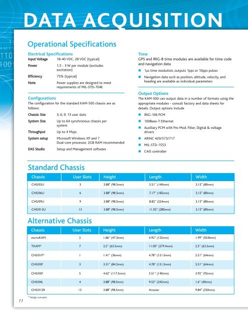
DATA ACQUISITION Operational Specifications Electrical Specifications Input Voltage 18-40 VDC, 28 VDC (typical) Power Efficiency Note 1.5 - 3 W per module (excludes excitation) 75% (typical) Power supplies are designed to meet requirements of MIL-STD-704E Configurations The configuration for the standard KAM-500 chassis are as follows: Chassis Size 3, 6, 9, 13 user slots System Size Up to 64 synchronous chassis per system Throughput Up to 4 Msps System setup Microsoft Windows XP and 7 Dual-core processor, 2GB RAM recommended DAS Studio Setup and Management software Time GPS and IRIG-B time modules are available for time code and navigation data 1µs time resolution, outputs 1pps or 10pps pulses Navigation data such as position, altitude, velocity, and heading are available as individual parameters Output Options The KAM-500 can output data in a number of formats using the appropriate modules - consult factory and data sheets for details. Output options include IRIG-106 PCM 100Base-T Ethernet Auxiliary PCM with Pre-Mod. Filter, Digital & voltage drivers ARINC 429/573/717 MIL-STD-1553 CAIS controller Standard Chassis Chassis User Slots Height Length Width CHS/03U 3 3.88" (98.5mm) 5.51” (140mm) 3.15" (80mm) CHS/06U 6 3.88" (98.5mm) 7.17” (182mm) 3.15" (80mm) CHS/09U 9 3.88" (98.5mm) 8.82” (224mm) 3.15" (80mm) CHS/013U 13 3.88" (98.5mm) 11.02” (280mm) 3.15" (80mm) Alternative Chassis Chassis User Slots Height Length Width microKAM 2 1.86” (47.3mm) 4.92” (125mm) 1.99” (50.8mm) TKAM* 7 2.5” (63.5mm) 11.00” (279.4mm) 2.5” (63.5mm) CHS/01F* 1 1.41” (36mm) 4.78” (121.5mm) 2.51” (64mm) CHS/03F 3 3.31” (84.2mm) 4.78” (121.5mm) 2.51” (64mm) CHS/05F 5 4.62” (117.5mm) 5.51” (140mm) 3.92” (92mm) CHS/04L 4 3.88" (98.5mm) 9.52” (242mm) 1.6” (40mm) CHS/012R 13 3.88" (98.5mm) Annular 9.84" (250mm) 11 * design concepts
PRODUCT GUIDE Environmental Specifications Operating Temperature MIL-STD-810F Methods 501.4 and 502.4 Procedure II -40°C to 85°C, at least 4 hours after stabilization Storage Temperature MIL-STD-810F Methods 501.4 and 502.4 Procedure I -55°C to 105°C, at least 4 hours after stabilization Altitude MIL-STD-810F Method 500.4 Procedure II Maximum pressure of 115Kpa (1150mbar) and a minimum pressure of 3.6Kpa (36mbar) Rapid Decompression MIL-STD-810F Method 500.4 Procedure III room ambient to 3.6Kpa at a rate of 218Kpa/minute (2180mbar/min.) Explosive Decompression MIL-STD-810F Method 500.4 Procedure IV Unit unpowered and a pressure change from 2,438m (8000ft) to 12,192m (40,000ft) was achieved in 78.4ms Shock MIL-STD-810F Method 516.5 Procedure V - modified 100g, 11ms, terminal peak sawtooth 12 (two in each direction of three mutually perpendicular axes) Sinusoidal Vibration MIL-STD-810F Method 514.5 Procedure I Frequency Range 10 - 2000Hz Amplitude 10g Sweep rate One octave per minute Random Vibration MIL-STD-810F Method 514.5 Procedure I 60 minutes per axis Random Endurance, 17grms 0.04g2/Hz from 15 to 89.2Hz 4dB/octave from 89.2 to 300Hz 0.2g2/Hz from 300 to 1000Hz -6dB/octave from 1000 to 2000Hz 10 minutes per axis Random Endurance, 33grms Frequency range 15-2000Hz Spectrum 0.04g2/Hz from 15 to 30.7Hz 4dB/octave from 30.7 to 300Hz 0.83g2/Hz from 300 to 1000Hz -6dB/octave from 1000 to 2000Hz Acceleration Operational MIL-STD-810F Method 513.5 Procedure II 16.5 in each direction of three mutually perpendicular axes Duration Minimum of one minute in each direction Water Ingress (Drip Test) MIL-STD-810F Method 506.4 Procedure III Precipitation rate 280l/m2/hr. Duration 45 minutes, divided equally between three faces (one side, one end and one top) Humidity MIL-STD-810F Method 507.4 Upper temperature 60°C Intermediate temperature 30°C Lower temperature 20°C Relative humidity 95% (>85%during temperature reduction) Dwell times Four hours at each level Cycle duration 24 hours Number of cycles: Five EMI/EMC MIL-STD-461E CE101 (30Hz to 10kHz) CE102 (10kHz to 10MHz) CS101 (30Hz to 150kHz) CS114 (30Hz to 150kHz) CS115 CS116 (10kHz to 100MHz) RE102 (10kHz to 18GHz) RS103 (10kHz to 1GHz, 70V/m) RS103 (400MHz to 18GHz 200V/m) BS3G100 Part 2, Section 2 Magnetic influence, compass safe distance ESD EN61000-4-2:1995 Contact discharge Level 4, 8kV Air discharge Level 4, 15kV Electrical Bonding and Insulation BS3G100, Part 4 Electrical insulation test, high voltage test BS3G100, Part 4 Electrical insulation test, insulation resistance test BS3G100, Part 4 Electrical insulation test, leakage current measurements Contamination Testing BS 3G 100, Part 2, section 3, subsection 3.12 Class A for Occasional Contamination 70 °C, for 93 hours Fluids tested include Propan-2-Ol Ethylene Glycol (50% v/v in water) AVTUR F-34 Aeroshell Turbine Oil 308 Aeroshell Fluid 31 Aeroshell F31 MIL-PRF-23699-F Salt Fog Testing MIL-STD-810F Method 509.4 24 hours exposure, 24 hours drying repeated twice Salt Fall out: 1 to 3ml/80cm2/hr Salt solution: 5 +/- 1% concentration Salt Mix pH: 6.5 to 7.2 Temperature: 35°C+/-2°C 12
- Page 1 and 2: PRODUCT GUIDE DATA ACQUISITION KAM-
- Page 3 and 4: PRODUCT GUIDE One Product, Many App
- Page 5 and 6: PRODUCT GUIDE Compact, Low Power Th
- Page 7 and 8: PRODUCT GUIDE Bus Monitors The avio
- Page 9 and 10: PRODUCT GUIDE DAS Studio DAS Studio
- Page 11: PRODUCT GUIDE Related Products GS W
- Page 15 and 16: PRODUCT GUIDE Module Selection Guid
<strong>DATA</strong> ACQUISITION<br />
Operational Specifications<br />
Electrical Specifications<br />
Input Voltage 18-40 VDC, 28 VDC (typical)<br />
Power<br />
Efficiency<br />
Note<br />
1.5 - 3 W per module (excludes<br />
excitation)<br />
75% (typical)<br />
Power supplies are designed to meet<br />
requirements of MIL-STD-704E<br />
Configurations<br />
The configuration for the standard KAM-500 chassis are as<br />
follows:<br />
Chassis Size 3, 6, 9, 13 user slots<br />
System Size Up to 64 synchronous chassis per<br />
system<br />
Throughput Up to 4 Msps<br />
System setup Microsoft Windows XP and 7<br />
Dual-core processor, 2GB RAM recommended<br />
DAS Studio Setup and Management software<br />
Time<br />
GPS and IRIG-B time modules are available for time code<br />
and navigation data<br />
<br />
<br />
1µs time resolution, outputs 1pps or 10pps pulses<br />
Navigation data such as position, altitude, velocity, and<br />
heading are available as individual parameters<br />
Output Options<br />
The KAM-500 can output data in a number of formats using the<br />
appropriate modules - consult factory and data sheets for<br />
details. Output options include<br />
IRIG-106 PCM<br />
100Base-T Ethernet<br />
Auxiliary PCM with Pre-Mod. Filter, Digital & voltage<br />
drivers<br />
ARINC 429/573/717<br />
MIL-STD-1553<br />
CAIS controller<br />
Standard Chassis<br />
Chassis User Slots Height Length Width<br />
CHS/03U 3 3.88" (98.5mm) 5.51” (140mm) 3.15" (80mm)<br />
CHS/06U 6 3.88" (98.5mm) 7.17” (182mm) 3.15" (80mm)<br />
CHS/09U 9 3.88" (98.5mm) 8.82” (224mm) 3.15" (80mm)<br />
CHS/013U 13 3.88" (98.5mm) 11.02” (280mm) 3.15" (80mm)<br />
Alternative Chassis<br />
Chassis User Slots Height Length Width<br />
microKAM 2 1.86” (47.3mm) 4.92” (125mm) 1.99” (50.8mm)<br />
TKAM* 7 2.5” (63.5mm) 11.00” (279.4mm) 2.5” (63.5mm)<br />
CHS/01F* 1 1.41” (36mm) 4.78” (121.5mm) 2.51” (64mm)<br />
CHS/03F 3 3.31” (84.2mm) 4.78” (121.5mm) 2.51” (64mm)<br />
CHS/05F 5 4.62” (117.5mm) 5.51” (140mm) 3.92” (92mm)<br />
CHS/04L 4 3.88" (98.5mm) 9.52” (242mm) 1.6” (40mm)<br />
CHS/012R 13 3.88" (98.5mm) Annular 9.84" (250mm)<br />
11<br />
* design concepts


