

Low Inductance Chip Capacitors InterDigitated Capacitor - AVX
Low Inductance Chip Capacitors InterDigitated Capacitor - AVX
Low Inductance Chip Capacitors InterDigitated Capacitor - AVX

Create successful ePaper yourself
Turn your PDF publications into a flip-book with our unique Google optimized e-Paper software.
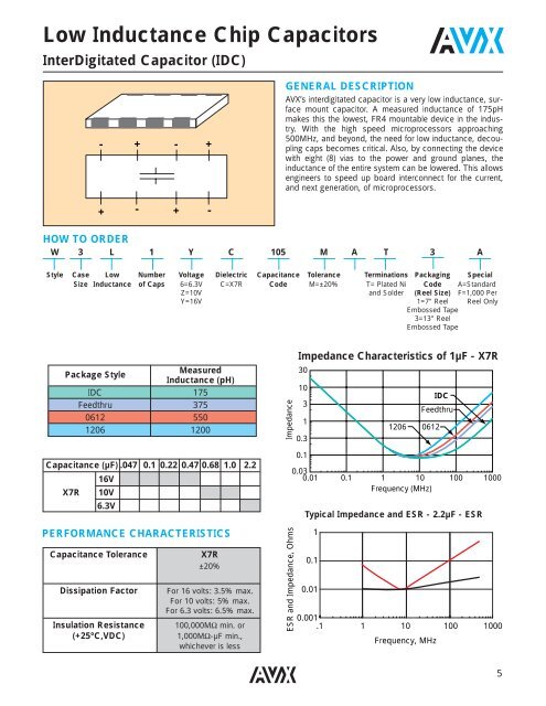
<strong>Low</strong> <strong>Inductance</strong> <strong>Chip</strong> <strong><strong>Capacitor</strong>s</strong><br />
<strong>InterDigitated</strong> <strong>Capacitor</strong> (IDC)<br />
- + - +<br />
GENERAL DESCRIPTION<br />
<strong>AVX</strong>’s interdigitated capacitor is a very low inductance, surface<br />
mount capacitor. A measured inductance of 175pH<br />
makes this the lowest, FR4 mountable device in the industry.<br />
With the high speed microprocessors approaching<br />
500MHz, and beyond, the need for low inductance, decoupling<br />
caps becomes critical. Also, by connecting the device<br />
with eight (8) vias to the power and ground planes, the<br />
inductance of the entire system can be lowered. This allows<br />
engineers to speed up board interconnect for the current,<br />
and next generation, of microprocessors.<br />
- + - +<br />
HOW TO ORDER<br />
W 3 L 1 Y C 105 M A T 3 A<br />
Style Case <strong>Low</strong> Number Voltage Dielectric Capacitance Tolerance Terminations Packaging Special<br />
Size <strong>Inductance</strong> of Caps 6=6.3V C=X7R Code M=±20% T= Plated Ni Code A=Standard<br />
Z=10V and Solder (Reel Size) F=1,000 Per<br />
Y=16V 1=7" Reel Reel Only<br />
Embossed Tape<br />
3=13" Reel<br />
Embossed Tape<br />
Package Style<br />
Measured<br />
<strong>Inductance</strong> (pH)<br />
IDC 175<br />
Feedthru 375<br />
0612 550<br />
1206 1200<br />
Capacitance (µF) .047 0.1 0.22 0.47 0.68 1.0 2.2<br />
16V<br />
X7R 10V<br />
6.3V<br />
PERFORMANCE CHARACTERISTICS<br />
Capacitance Tolerance<br />
Dissipation Factor<br />
Insulation Resistance<br />
(+25°C,VDC)<br />
X7R<br />
±20%<br />
For 16 volts: 3.5% max.<br />
For 10 volts: 5% max.<br />
For 6.3 volts: 6.5% max.<br />
100,000MΩ min. or<br />
1,000MΩ-µF min.,<br />
whichever is less<br />
Impedance<br />
ESR and Impedance, Ohms<br />
Impedance Characteristics of 1µF - X7R<br />
30<br />
10<br />
3<br />
1<br />
0.3<br />
0.1<br />
Typical Impedance and ESR - 2.2µF - ESR<br />
1<br />
0.1<br />
0.01<br />
1206<br />
IDC<br />
Feedthru<br />
0612<br />
0.03<br />
0.01 0.1 1 10 100 1000<br />
Frequency (MHz)<br />
0.001<br />
.1 1 10 100<br />
Frequency, MHz<br />
1000<br />
5
<strong>Low</strong> <strong>Inductance</strong> <strong>Chip</strong> <strong><strong>Capacitor</strong>s</strong><br />
<strong>InterDigitated</strong> <strong>Capacitor</strong> (IDC)<br />
PHYSICAL DIMENSIONS AND PAD LAYOUT<br />
L<br />
X<br />
P<br />
S<br />
S<br />
X<br />
T<br />
E<br />
D<br />
BW<br />
C L<br />
C/L OF CHIP<br />
A<br />
B<br />
C<br />
BL<br />
W<br />
PART DIMENSIONS millimeters (inches)<br />
L W T BW BL P X S<br />
+0.25<br />
3.20±0.2 1.60±0.2 1.22 MAX 0.41±0.1 0.18 -0.08 0.76 REF 1.14±0.1 0.38±0.1<br />
(.126±.008) (.063±.008) (.048 MAX) (.016±.004) (.007<br />
+.010<br />
) (.030 REF) (.045±.004) (.015±.004)<br />
-.003<br />
PAD LAYOUT DIMENSIONS<br />
A B C D E<br />
0.89 1.65 2.54 0.46 0.79<br />
(.035) (.065) (.100) (.018) (.030)<br />
ASSEMBLY NOTES<br />
<strong>AVX</strong> recommends a minimum spacing of 0.020" between parts when placing them end to end on assembly boards. The purpose<br />
of this spacing is to facilitate post assembly board cleaning and inaccuracies in pick and placement, due to machine<br />
placement tolerances.<br />
6


