Phase Cycling and Gradient Pulses - The James Keeler Group
Phase Cycling and Gradient Pulses - The James Keeler Group
Phase Cycling and Gradient Pulses - The James Keeler Group

You also want an ePaper? Increase the reach of your titles
YUMPU automatically turns print PDFs into web optimized ePapers that Google loves.
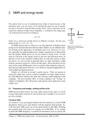
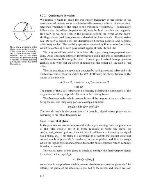
y<br />
<strong>The</strong> x <strong>and</strong> y projections of the<br />
black vector are both positive.<br />
If the vector had precessed in<br />
the opposite direction (shown<br />
shaded), <strong>and</strong> at the same<br />
frequency, the projection along<br />
x would be the same, but along<br />
y it would be minus that of the<br />
black vector.<br />
θ<br />
x<br />
9.2.2 Quadrature detection<br />
We normally want to place the transmitter frequency in the centre of the<br />
resonances of interest so as to minimise off-resonance effects. If the receiver<br />
reference frequency is the same as the transmitter frequency, it immediately<br />
follows that the offset frequencies, Ω, may be both positive <strong>and</strong> negative.<br />
However, as we have seen in the previous section the effect of the downshifting<br />
scheme used is to generate a signal of the form cos Ωt. Since cos(θ) =<br />
cos(–θ) such a signal does not discriminate between positive <strong>and</strong> negative<br />
offset frequencies. <strong>The</strong> resulting spectrum, obtained by Fourier transformation,<br />
would be confusing as each peak would appear at both +Ω <strong>and</strong> –Ω.<br />
<strong>The</strong> way out of this problem is to detect the signal along two perpendicular<br />
axes. As is illustrated opposite, the projection along one axis is proportional to<br />
cos(Ωt) <strong>and</strong> to sin(Ωt) along the other. Knowledge of both of these projections<br />
enables us to work out the sense of rotation of the vector i.e. the sign of the<br />
offset.<br />
<strong>The</strong> sin modulated component is detected by having a second mixer fed with<br />
a reference whose phase is shifted by π/2. Following the above discussion the<br />
output of the mixer is<br />
cos( Ωt−<br />
π 2)= cosΩtcosπ 2+<br />
sinΩtsinπ<br />
2<br />
= sinΩt<br />
<strong>The</strong> output of these two mixers can be regarded as being the components of the<br />
magnetization along perpendicular axes in the rotating frame.<br />
<strong>The</strong> final step in this whole process is regard the outputs of the two mixers as<br />
being the real <strong>and</strong> imaginary parts of a complex number:<br />
cosΩt + isinΩt = exp( iΩt)<br />
<strong>The</strong> overall result is the generation of a complex signal whose phase varies<br />
according to the offset frequency Ω.<br />
9.2.3 Control of phase<br />
In the previous section we supposed that the signal coming from the probe was<br />
of the form cosω 0<br />
t but it is more realistic to write the signal as<br />
cos(ω 0<br />
t + φ sig<br />
) in recognition of the fact that in addition to a frequency the signal<br />
has a phase, φ sig<br />
. This phase is a combination of factors that are not under our<br />
control (such as phase shifts produced in the amplifiers <strong>and</strong> filters through<br />
which the signal passes) <strong>and</strong> a phase due to the pulse sequence, which certainly<br />
is under our control.<br />
<strong>The</strong> overall result of this phase is simply to multiply the final complex signal<br />
by a phase factor, exp(iφ sig<br />
):<br />
( ) ( iφ<br />
sig )<br />
exp iΩt<br />
exp<br />
As we saw in the previous section, we can also introduce another phase shift by<br />
altering the phase of the reference signal fed to the mixer, <strong>and</strong> indeed we saw<br />
9–4