Phase Cycling and Gradient Pulses - The James Keeler Group
Phase Cycling and Gradient Pulses - The James Keeler Group
Phase Cycling and Gradient Pulses - The James Keeler Group
Create successful ePaper yourself
Turn your PDF publications into a flip-book with our unique Google optimized e-Paper software.
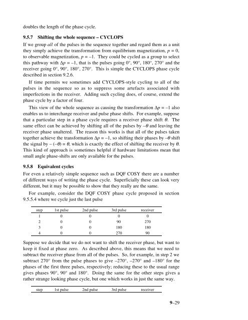
doubles the length of the phase cycle.<br />
9.5.7 Shifting the whole sequence – CYCLOPS<br />
If we group all of the pulses in the sequence together <strong>and</strong> regard them as a unit<br />
they simply achieve the transformation from equilibrium magnetization, p = 0,<br />
to observable magnetization, p = –1. <strong>The</strong>y could be cycled as a group to select<br />
this pathway with ∆p = –1, that is the pulses going 0°, 90°, 180°, 270° <strong>and</strong> the<br />
receiver going 0°, 90°, 180°, 270°. This is simple the CYCLOPS phase cycle<br />
described in section 9.2.6.<br />
If time permits we sometimes add CYCLOPS-style cycling to all of the<br />
pulses in the sequence so as to suppress some artefacts associated with<br />
imperfections in the receiver. Adding such cycling does, of course, extend the<br />
phase cycle by a factor of four.<br />
This view of the whole sequence as causing the transformation ∆p = –1 also<br />
enables us to interchange receiver <strong>and</strong> pulse phase shifts. For example, suppose<br />
that a particular step in a phase cycle requires a receiver phase shift θ. <strong>The</strong><br />
same effect can be achieved by shifting all of the pulses by –θ <strong>and</strong> leaving the<br />
receiver phase unaltered. <strong>The</strong> reason this works is that all of the pulses taken<br />
together achieve the transformation ∆p = –1, so shifting their phases by –θ shift<br />
the signal by – (–θ) = θ, which is exactly the effect of shifting the receiver by θ.<br />
This kind of approach is sometimes helpful if hardware limitations mean that<br />
small angle phase-shifts are only available for the pulses.<br />
9.5.8 Equivalent cycles<br />
For even a relatively simple sequence such as DQF COSY there are a number<br />
of different ways of writing the phase cycle. Superficially these can look very<br />
different, but it may be possible to show that they really are the same.<br />
For example, consider the DQF COSY phase cycle proposed in section<br />
9.5.5.4 where we cycle just the last pulse<br />
step 1st pulse 2nd pulse 3rd pulse receiver<br />
1 0 0 0 0<br />
2 0 0 90 270<br />
3 0 0 180 180<br />
4 0 0 270 90<br />
Suppose we decide that we do not want to shift the receiver phase, but want to<br />
keep it fixed at phase zero. As described above, this means that we need to<br />
subtract the receiver phase from all of the pulses. So, for example, in step 2 we<br />
subtract 270° from the pulse phases to give –270°, –270° <strong>and</strong> –180° for the<br />
phases of the first three pulses, respectively; reducing these to the usual range<br />
gives phases 90°, 90° <strong>and</strong> 180°. Doing the same for the other steps gives a<br />
rather strange looking phase cycle, but one which works in just the same way.<br />
step 1st pulse 2nd pulse 3rd pulse receiver<br />
9–29


