Phase Cycling and Gradient Pulses - The James Keeler Group
Phase Cycling and Gradient Pulses - The James Keeler Group
Phase Cycling and Gradient Pulses - The James Keeler Group

You also want an ePaper? Increase the reach of your titles
YUMPU automatically turns print PDFs into web optimized ePapers that Google loves.
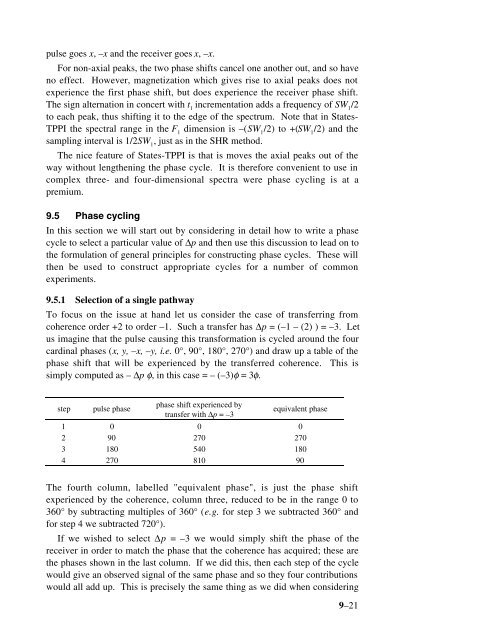
pulse goes x, –x <strong>and</strong> the receiver goes x, –x.<br />
For non-axial peaks, the two phase shifts cancel one another out, <strong>and</strong> so have<br />
no effect. However, magnetization which gives rise to axial peaks does not<br />
experience the first phase shift, but does experience the receiver phase shift.<br />
<strong>The</strong> sign alternation in concert with t 1<br />
incrementation adds a frequency of SW 1<br />
/2<br />
to each peak, thus shifting it to the edge of the spectrum. Note that in States-<br />
TPPI the spectral range in the F 1<br />
dimension is –(SW 1<br />
/2) to +(SW 1<br />
/2) <strong>and</strong> the<br />
sampling interval is 1/2SW 1<br />
, just as in the SHR method.<br />
<strong>The</strong> nice feature of States-TPPI is that is moves the axial peaks out of the<br />
way without lengthening the phase cycle. It is therefore convenient to use in<br />
complex three- <strong>and</strong> four-dimensional spectra were phase cycling is at a<br />
premium.<br />
9.5 <strong>Phase</strong> cycling<br />
In this section we will start out by considering in detail how to write a phase<br />
cycle to select a particular value of ∆p <strong>and</strong> then use this discussion to lead on to<br />
the formulation of general principles for constructing phase cycles. <strong>The</strong>se will<br />
then be used to construct appropriate cycles for a number of common<br />
experiments.<br />
9.5.1 Selection of a single pathway<br />
To focus on the issue at h<strong>and</strong> let us consider the case of transferring from<br />
coherence order +2 to order –1. Such a transfer has ∆p = (–1 – (2) ) = –3. Let<br />
us imagine that the pulse causing this transformation is cycled around the four<br />
cardinal phases (x, y, –x, –y, i.e. 0°, 90°, 180°, 270°) <strong>and</strong> draw up a table of the<br />
phase shift that will be experienced by the transferred coherence. This is<br />
simply computed as – ∆p φ, in this case = – (–3)φ = 3φ.<br />
step<br />
pulse phase<br />
phase shift experienced by<br />
transfer with ∆p = –3<br />
equivalent phase<br />
1 0 0 0<br />
2 90 270 270<br />
3 180 540 180<br />
4 270 810 90<br />
<strong>The</strong> fourth column, labelled "equivalent phase", is just the phase shift<br />
experienced by the coherence, column three, reduced to be in the range 0 to<br />
360° by subtracting multiples of 360° (e.g. for step 3 we subtracted 360° <strong>and</strong><br />
for step 4 we subtracted 720°).<br />
If we wished to select ∆p = –3 we would simply shift the phase of the<br />
receiver in order to match the phase that the coherence has acquired; these are<br />
the phases shown in the last column. If we did this, then each step of the cycle<br />
would give an observed signal of the same phase <strong>and</strong> so they four contributions<br />
would all add up. This is precisely the same thing as we did when considering<br />
9–21