Phase Cycling and Gradient Pulses - The James Keeler Group
Phase Cycling and Gradient Pulses - The James Keeler Group
Phase Cycling and Gradient Pulses - The James Keeler Group

You also want an ePaper? Increase the reach of your titles
YUMPU automatically turns print PDFs into web optimized ePapers that Google loves.
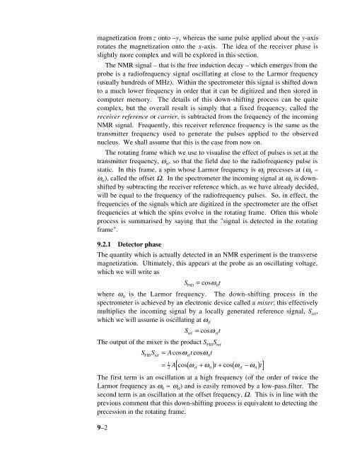
magnetization from z onto –y, whereas the same pulse applied about the y-axis<br />
rotates the magnetization onto the x-axis. <strong>The</strong> idea of the receiver phase is<br />
slightly more complex <strong>and</strong> will be explored in this section.<br />
<strong>The</strong> NMR signal – that is the free induction decay – which emerges from the<br />
probe is a radiofrequency signal oscillating at close to the Larmor frequency<br />
(usually hundreds of MHz). Within the spectrometer this signal is shifted down<br />
to a much lower frequency in order that it can be digitized <strong>and</strong> then stored in<br />
computer memory. <strong>The</strong> details of this down-shifting process can be quite<br />
complex, but the overall result is simply that a fixed frequency, called the<br />
receiver reference or carrier, is subtracted from the frequency of the incoming<br />
NMR signal. Frequently, this receiver reference frequency is the same as the<br />
transmitter frequency used to generate the pulses applied to the observed<br />
nucleus. We shall assume that this is the case from now on.<br />
<strong>The</strong> rotating frame which we use to visualise the effect of pulses is set at the<br />
transmitter frequency, ω rf<br />
, so that the field due to the radiofrequency pulse is<br />
static. In this frame, a spin whose Larmor frequency is ω 0<br />
precesses at (ω 0<br />
–<br />
ω rf<br />
), called the offset Ω. In the spectrometer the incoming signal at ω 0<br />
is downshifted<br />
by subtracting the receiver reference which, as we have already decided,<br />
will be equal to the frequency of the radiofrequency pulses. So, in effect, the<br />
frequencies of the signals which are digitized in the spectrometer are the offset<br />
frequencies at which the spins evolve in the rotating frame. Often this whole<br />
process is summarised by saying that the "signal is detected in the rotating<br />
frame".<br />
9.2.1 Detector phase<br />
<strong>The</strong> quantity which is actually detected in an NMR experiment is the transverse<br />
magnetization. Ultimately, this appears at the probe as an oscillating voltage,<br />
which we will write as<br />
S = cosω FID 0t<br />
where ω 0<br />
is the Larmor frequency. <strong>The</strong> down-shifting process in the<br />
spectrometer is achieved by an electronic device called a mixer; this effectively<br />
multiplies the incoming signal by a locally generated reference signal, S ref<br />
,<br />
which we will assume is oscillating at ω rf<br />
Sref<br />
= cosω<br />
rft<br />
<strong>The</strong> output of the mixer is the product S FID<br />
S ref<br />
S S = Acosω<br />
tcosω<br />
t<br />
9–2<br />
FID ref rf 0<br />
1<br />
=<br />
2<br />
A[ cos( ωrf<br />
+ ω0) t + cos( ωrf<br />
−ω0)<br />
t]<br />
<strong>The</strong> first term is an oscillation at a high frequency (of the order of twice the<br />
Larmor frequency as ω 0<br />
≈ ω rf<br />
) <strong>and</strong> is easily removed by a low-pass filter. <strong>The</strong><br />
second term is an oscillation at the offset frequency, Ω. This is in line with the<br />
previous comment that this down-shifting process is equivalent to detecting the<br />
precession in the rotating frame.