
Create successful ePaper yourself
Turn your PDF publications into a flip-book with our unique Google optimized e-Paper software.
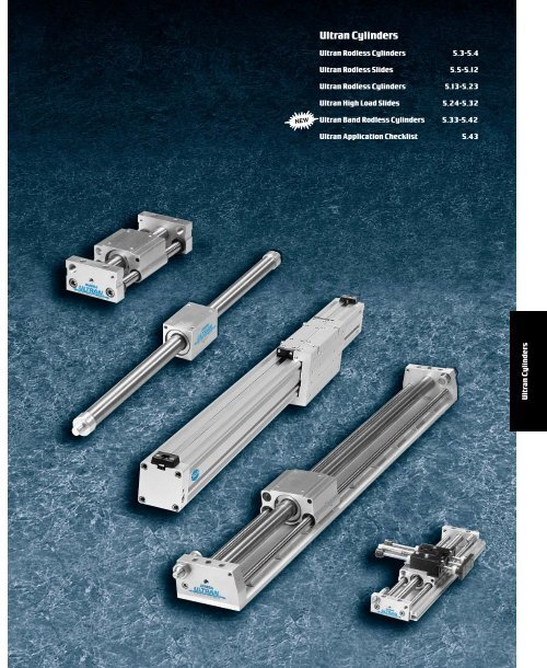
<strong>Ultran</strong><strong>Cylinders</strong><br />
<strong>Ultran</strong>Rodless <strong>Cylinders</strong> 5.3-5.4<br />
<strong>Ultran</strong>Rodless Slides 5.5-5.12<br />
<strong>Ultran</strong>Rodless <strong>Cylinders</strong> 5.13-5.23<br />
<strong>Ultran</strong>High Load Slides 5.24-5.32<br />
NEW<br />
<strong>Ultran</strong>Band Rodless <strong>Cylinders</strong> 5.33-5.42<br />
<strong>Ultran</strong>Application Checklist 5.43<br />
<strong>Ultran</strong><strong>Cylinders</strong>
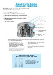
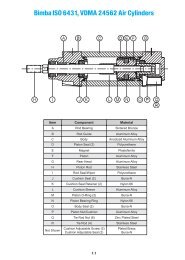
Bimba <strong>Ultran</strong> <strong>Cylinders</strong><br />
SPACE SAVINGS OF ALMOST 50% IN MOST MODELS<br />
Two Models:<br />
• <strong>Ultran</strong> Slide for self-guided motion<br />
• <strong>Ultran</strong> for unguided or externally guided applications.<br />
Anodized aluminum end blocks<br />
304 stainless steel body<br />
Anodized aluminum carriage<br />
Carriage lubrication fitting (Not available for 5/16" bore)<br />
Threaded mounting holes<br />
Carriage magnetically coupled to piston<br />
Composite self-lubricating bearings -<br />
protected by wipers (wipers omitted on 5/16” bore thru 9/16” bore)<br />
Hard chrome plated carbon steel guide rods<br />
Stainless steel socket head cap screws<br />
<strong>Ultran</strong><strong>Cylinders</strong><br />
ADVANTAGES<br />
• Leak-free construction.<br />
• Lightweight.<br />
• Piston seals are internally lubricated<br />
for long life.<br />
• Special rare earth magnet configuration<br />
for high magnetic coupling strengths.<br />
• 304 stainless steel body and “U” cup seals<br />
for lower dynamic friction.<br />
• Prelubricated for miles of maintenance-free travel,<br />
with easily-accessible carriage lubrication port.<br />
• Twomagnetic coupling strength options available —<br />
<strong>Ultran</strong> Gold and <strong>Ultran</strong> Silver.<br />
• Shock absorbers to decelerate loads<br />
(not available for 5/16" and 7/16" bore <strong>Ultran</strong>).<br />
• Optional 1-inch stroke length adjustment available.<br />
• Midstroke position sensing available for <strong>Ultran</strong> Slide.<br />
End-of-stroke sensing available for all models.<br />
• Optional bumpers to reduce noise.<br />
<strong>Ultran</strong> Slide<br />
Zinc-plated steel mounting nuts<br />
304 stainless steel body<br />
Threaded mounting holes<br />
High strength anodized<br />
aluminum alloy carriage<br />
Carriage lubrication<br />
fitting (Not available<br />
for 5/16" bore)<br />
Carriage<br />
magnetically<br />
coupled to piston<br />
Double-rolled<br />
construction<br />
Anodized<br />
aluminum<br />
end caps<br />
• Floating mount available for <strong>Ultran</strong>.<br />
• Oil service seal option available for low pressure hydraulic service.<br />
• Optional adjustable cushions or axial ports on <strong>Ultran</strong><br />
(not available for 5/16" or 7/16" bore, 9/16" bore has fixed cushion).<br />
<strong>Ultran</strong><br />
5.2
Bimba <strong>Ultran</strong> Rodless<strong>Cylinders</strong><br />
CARRIAGE MAGNET<br />
PISTON MAGNET<br />
<strong>Ultran</strong> Slide<br />
PISTON<br />
END BLOCK<br />
CAP SCREW<br />
<strong>Ultran</strong> Rodless<br />
<strong>Cylinders</strong><br />
PISTON BEARING<br />
<strong>Ultran</strong> Rodless<br />
Slides<br />
<strong>Ultran</strong> Rodless<br />
<strong>Cylinders</strong><br />
TUBE SEAL<br />
PISTON SEAL<br />
CARRIAGE<br />
SHAFT WIPER (NOT ON<br />
5/16", 7/16", AND 9/16"<br />
<strong>Ultran</strong><br />
CARRIAGE WIPER (NOT AVAILABLE ON<br />
5/16" BORE)<br />
GUIDE ROD<br />
CARRIAGE BEARING<br />
SHAFT BEARING<br />
<strong>Ultran</strong> High Load<br />
Slides<br />
<strong>Ultran</strong> Band<br />
Rodless <strong>Cylinders</strong><br />
CARRIAGE<br />
INTERNALLY LUBRICATED<br />
BEARINGS<br />
URETHANE CARRIAGE WIPERS<br />
(NOT ON 5/16" BORE)<br />
OVERSIZED<br />
END CAPS<br />
<strong>Ultran</strong> Application<br />
Checklist<br />
INTERNALLY LUBRICATED<br />
PISTON SEAL<br />
STAINLESS STEEL TUBING<br />
STEEL WASHER<br />
PISTON<br />
MAGNET<br />
CARRIAGE GREASE FITTING<br />
The cutaway drawings above show how the Bimba<br />
magnetically-coupled <strong>Ultran</strong> rodless cylinder works.<br />
Three magnets are located on the carriage. Three<br />
matching magnets are onthe piston. (For 5/16" bore,<br />
five magnets are used.) These magnets form astrong<br />
bond that holds the carriage and piston together. When<br />
the cylinder is actuated, the piston and carriage move<br />
back and forth as one unit.<br />
The magnetic attraction between the magnets determines<br />
acylinder's magnetic coupling strength.<br />
The Bimba <strong>Ultran</strong> rodless cylinder provides one of the<br />
highest coupling strengths available. This means it can<br />
carry higher loads without causing the piston to uncouple<br />
from the carriage. Bimba also offers two magnetic<br />
coupling strength options (Gold and Silver) to suit a<br />
wide variety of applications. The Silver option uses two<br />
sets of magnets instead of three. (For 5/16" bore, four<br />
sets of magnets are used.)<br />
Bimba offers amodel with built-in guides (<strong>Ultran</strong> Slide)<br />
and an unguided unit (<strong>Ultran</strong>).<br />
5.3 ForTechnical Assistance: 800-442-4622
Bimba <strong>Ultran</strong> Rodless<strong>Cylinders</strong><br />
Application Possibilities<br />
Save space and streamline your design with the Bimba <strong>Ultran</strong> rodless cylinder.<br />
LOAD<br />
STROKE<br />
OVERALL LENGTH<br />
LOAD<br />
OVERALL LENGTH ORIGINAL LINE =<br />
2xOVERALL LENGTH RODLESS CYLINDER<br />
STROKE<br />
OVERALL LENGTH<br />
Overall Length Savings<br />
Transferring<br />
Feeding<br />
Door Opening<br />
Cutting<br />
Silk Screening<br />
5.4
Bimba <strong>Ultran</strong> RodlessSlides<br />
The model number of all <strong>Ultran</strong> Slide cylinders consists<br />
of three alphanumeric clusters. These designate<br />
product type, bore size and stroke length, and options.<br />
Please refer to the charts below for an example of<br />
model number UGS-1723.375-A1T.<br />
TYPE<br />
UGS-<strong>Ultran</strong> Slide,<br />
Gold coupling strength<br />
USS-<strong>Ultran</strong> Slide,*<br />
Silver coupling strength<br />
SIZES<br />
OPTIONS<br />
FOR ALL SIZES<br />
HowtoOrder<br />
UGS-1723.375-A1T<br />
BORE SIZE<br />
007 - 5/16"<br />
01 - 7/16"<br />
02 - 9/16"<br />
04 - 3/4"<br />
06 - 7/8"<br />
09 - 1-1/16"<br />
12 - 1-1/4"<br />
17 - 1-1/2"<br />
31 - 2"<br />
This is a1-1/2" bore, 23.375" stroke <strong>Ultran</strong> Slide<br />
rodless cylinder with <strong>Ultran</strong> Gold coupling strength,<br />
with stroke adjustment on one end, and atrack for<br />
mounting switches.<br />
STROKE LENGTH<br />
STANDARD MAXIMUM<br />
1/4" to 15" (007)<br />
1/4" to 20" (01)<br />
1/4" to 30" (02)<br />
1/4" to 30" (04)<br />
1/4" to 40" (06)<br />
1/4" to 60" (09)<br />
1/4" to 60" (12)<br />
1/4" to 60" (17)<br />
1/4" to 60" (31)<br />
*Specify silver coupling strengths for lower breakaway application requirements.<br />
Use caution as decoupling can occur at pressures less than 100 PSI.<br />
Refer to the engineering specifications on page 5.10 for details.<br />
Combination Availability<br />
A B D S T, U Y<br />
OPTIONS<br />
A - Stroke adjustment (both ends)<br />
A1 - Stroke adjustment (on end 1)<br />
A2 - Stroke adjustment (on end 2)<br />
B - Bumpers (both ends) 1<br />
B1 - Bumpers (on end 1)<br />
B2 - Bumpers (on end 2)<br />
D - Dowel pin holes for Transition Plates 2<br />
L - Remove guide rod wipers in 3/4" -<br />
2" bores<br />
S - Seals –oil service (low pressure<br />
hydraulic service)<br />
T - Switch track<br />
U - Switch track for miniature switch<br />
Y - Alternate port (both ends)<br />
Y1 - Alternate port (on end 1)<br />
Y2 - Alternate port (on end 2)<br />
1 Increases overall dimension. Internal<br />
bumpers reach full compression at 80 psi.<br />
External bumpers will not contact carriage<br />
until internal bumpers are fully compressed.<br />
2 Transition Plate Applications: Option -D must<br />
be ordered if dowel pin holes are required.<br />
Not available on all bore sizes. Refer to<br />
Related Products/Transition Plates, page<br />
9.22-9.35 for details. Hole locations shown in<br />
Related Products/Appendix, page 9.39.<br />
D,S,T,Y D,T,Y A,B,D,S,T,Y A,D,T,Y A,B,D,S,Y A,B,D,S,T<br />
Note: Option -A can be ordered with option -B if they are<br />
ordered on different ends, i.e., A1B2 or A2B1.<br />
25"<br />
30"<br />
40"<br />
40"<br />
50"<br />
70"<br />
70"<br />
85"<br />
100"<br />
<strong>Ultran</strong> Rodless<br />
<strong>Cylinders</strong><br />
<strong>Ultran</strong> Rodless<br />
Slides<br />
<strong>Ultran</strong> Rodless<br />
<strong>Cylinders</strong><br />
<strong>Ultran</strong> High Load<br />
Slides<br />
<strong>Ultran</strong> Band<br />
Rodless <strong>Cylinders</strong><br />
<strong>Ultran</strong> Application<br />
Checklist<br />
Location<br />
See diagram on page 5.7 for location of End 1and End 2.<br />
5.5 ForTechnical Assistance: 800-442-4622
Bore<br />
Base Model<br />
UGS<br />
Bimba <strong>Ultran</strong> RodlessSlides<br />
USS<br />
Adder<br />
per inch<br />
of stroke*<br />
List Prices<br />
Options<br />
A B D S T Y<br />
Stroke<br />
Adjustment<br />
(per end)<br />
Bumpers<br />
(per end)<br />
Dowel Pin<br />
Holes<br />
Oil Service<br />
Seals<br />
Switch<br />
Track<br />
(Base)<br />
Adder per<br />
inch of<br />
stroke<br />
Alternate<br />
Port (per<br />
end)<br />
5/16" (007) $221.20 $216.10 $1.70 $5.70 $21.50 N/A $3.70 $10.50 $0.35 $1.90<br />
7/16" (01) 236.10 234.00 1.90 5.70 23.50 N/A 4.00 10.50 0.35 2.10<br />
9/16" (02) 296.30 288.90 2.20 7.60 25.60 9.70 4.70 10.50 0.35 2.40<br />
3/4" (04) 432.80 402.90 3.80 7.60 27.00 11.20 5.30 10.50 0.35 2.70<br />
7/8" (06) 453.10 419.60 4.00 8.20 27.70 N/A 5.60 10.50 0.35 3.00<br />
1-1/16" (09) 574.00 532.10 6.00 8.20 29.40 13.00 5.90 10.50 0.35 3.50<br />
1-1/4" (12) 621.90 589.30 6.20 9.80 32.30 N/A 6.30 10.50 0.35 4.00<br />
1-1/2" (17) 822.90 784.00 8.10 9.80 34.80 15.40 6.80 10.50 0.35 4.60<br />
2" (31) 3343.10 2856.20 9.40 11.50 34.90 N/A 7.20 10.50 0.35 4.90<br />
* Longer than standard stroke lengths incur additional charge. Consult your distributor for details.<br />
No charge option -L<br />
Accessories<br />
Bore<br />
5/16" (007)<br />
7/16" (01)<br />
Shock Absorbers Stroke Adjustment *Stop Collar<br />
Model<br />
Light Standard Heavy<br />
Price<br />
(each)<br />
Model Model Price<br />
LS-02 SS-02 HS-02 $27.75 USA-01 $5.65 N/A N/A<br />
9/16" (02)<br />
LS-04 SS-04 HS-04 52.15<br />
USA-02 6.80<br />
3/4" (04) USA-04 7.65<br />
7/8" (06)<br />
1-1/16" (09)<br />
1-1/4" (12)<br />
1-1/2" (17)<br />
USC-04 $10.10<br />
LS-09 SS-09 HS-09 63.80 USA-09 8.30 USC-09 10.10<br />
LS-17 SS-17 HS-17 79.65 USA-17 9.90 USC-17 14.45<br />
2" (31) LS-31 SS-31 HS-31 156.40 USA-31 12.15 USC-31 29.25<br />
* The <strong>Ultran</strong> Slide Cylinder needs to be increased by the Bdimension in order to maintain intended stroke length. The overall length increases by<br />
the same amount. The Adimension indicates maximum amount of stroke adjustment attainable. See Related Products, page 9.20 for<br />
dimensions.<br />
All prices are F.O.B. Monee, Illinois and are subject to change without notice<br />
5.6
Bimba <strong>Ultran</strong> RodlessSlides<br />
D<br />
A<br />
H+STROKE<br />
C<br />
B<br />
L<br />
Dimensions (in.)<br />
Bore A B C D E F G H I J K<br />
5/16" (007) 0.344 1.062 1.750 0.141 0.469 4-40 UNC 1.062 2.750 0.250 0.188 0.438<br />
7/16" (01) 0.344 1.188 1.875 0.125 0.750 6-32 UNC 1.062 2.875 0.250 0.188 0.406<br />
9/16" (02) 0.375 1.500 2.250 0.250 1.000 8-32 UNC 1.438 3.250 0.250 0.312 0.531<br />
3/4" (04) 0.562 1.750 2.875 0.312 1.375 10-24 UNC 1.832 4.125 0.312 0.312 0.664<br />
7/8" (06) 0.500 2.125 3.125 0.188 1.625 10-24 UNC 2.062 4.625 0.375 0.375 0.688<br />
1-1/16" (09) 0.500 2.500 3.500 0.375 1.750 1/4-20 UNC 2.313 5.000 0.375 0.250 0.750<br />
1-1/4" (12) 0.562 2.750 3.875 0.318 2.125 1/4-20 UNC 2.687 5.875 0.500 0.500 0.750<br />
1-1/2" (17) 0.500 3.500 4.500 0.500 2.500 5/16-18 UNC 3.188 6.500 0.500 0.750 0.906<br />
2" (31) 1.188 5.000 7.375 0.500 3.250 1/2-13 UNC 4.312 10.375 0.750 0.813 1.312<br />
Bore L M N P Q R S V W X X/X<br />
5/16" (007) N/A N/A 0.750 N/A 0.188 0.500 2.000 0.215 0.215 1.000 0.562<br />
7/16" (01) 0.395 0.788 0.938 0.288 0.219 0.500 2.312 0.218 0.220 1.000 0.562<br />
9/16" (02) 0.455 0.982 1.250 0.297 0.250 0.500 3.000 0.406 0.281 1.375 0.749<br />
3/4" (04) 0.572 1.239 1.625 0.234 0.313 0.625 3.375 0.406 0.313 1.750 0.957<br />
7/8" (06) 0.635 1.438 1.625 0.225 0.312 0.750 3.750 0.500 0.438 2.000 1.063<br />
1-1/16" (09) 0.706 1.549 1.875 0.172 0.375 0.750 4.250 0.594 0.375 2.250 1.188<br />
1-1/4" (12) 0.750 1.562 2.125 0.162 0.375 1.000 4.812 0.656 0.562 2.625 1.375<br />
1-1/2" (17) 0.756 1.736 2.500 0.109 0.438 1.000 6.000 1.000 0.906 3.125 1.625<br />
2" (31) 1.500 2.688 3.250 0.000 0.250 1.500 8.000 1.125 0.938 4.250 2.188<br />
Bore Y Z AA BB CC DD EE AAA EEE<br />
5/16" (007) 0.312 1.312 #6 5/16-24 UNF 3/8-32 UNEF 10-32 10-32 UNF 0.750 0.315<br />
7/16" (01) 0.375 1.562 #10 5/16-24 UNF 3/8-32 UNEF 10-32 1/4-28 UNF 0.750 0.322<br />
9/16" (02) 0.438 2.000 #10 5/16-24 UNF 7/16-28 UNEF 10-32 1/4-28 UNF 0.750 0.500<br />
3/4" (04) 0.500 2.518 1/4 5/16-24 UNF 7/16-28 UNEF 1/8 NPT 5/16-24 UNF 1.080 0.625<br />
7/8" (06) 0.625 2.750 1/4 5/16-24 UNF 1/2-20 UNF 1/8 NPT 5/16-24 UNF 1.375 0.625<br />
1-1/16" (09) 0.750 3.062 5/16 5/16-24 UNF 1/2-20 UNF 1/8 NPT 3/8-24 UNF 1.375 0.750<br />
1-1/4" (12) 0.812 3.500 5/16 5/16-24 UNF 3/4-16 UNF 1/8 NPT 3/8-24 UNF 1.750 0.750<br />
1-1/2" (17) 1.000 4.500 3/8 5/16-24 UNF 3/4-16 UNF 1/8 NPT 7/16-20 UNF 1.750 0.750<br />
2" (31) 1.500 5.750 3/4 5/16-24 UNF 1-12 UNF 1/4 NPT 7/8-9 UNC 3.125 1.000<br />
NOTE: H+ stroke tolerance for stroke lengths less than 42" is +/- 0.032"<br />
For stroke lengths greater than 42" the tolerance is +0.104/-0.047".<br />
END 1<br />
Y<br />
R<br />
I<br />
END 2<br />
Q<br />
J<br />
G<br />
X<br />
M<br />
K<br />
AAA<br />
X/X<br />
P<br />
<strong>Ultran</strong> Rodless<br />
<strong>Cylinders</strong><br />
<strong>Ultran</strong> Rodless<br />
Slides<br />
<strong>Ultran</strong> Rodless<br />
<strong>Cylinders</strong><br />
<strong>Ultran</strong> High Load<br />
Slides<br />
<strong>Ultran</strong> Band<br />
Rodless <strong>Cylinders</strong><br />
<strong>Ultran</strong> Application<br />
Checklist<br />
BB<br />
EE<br />
E<br />
N<br />
DD<br />
CC<br />
EEE<br />
Z<br />
S<br />
V<br />
AA<br />
F<br />
W<br />
5.7 ForTechnical Assistance: 800-442-4622
Bimba <strong>Ultran</strong> RodlessSlides<br />
Options<br />
Option T<br />
Option U<br />
.625<br />
B<br />
(BOTH ENDS)<br />
D<br />
B<br />
(BOTH ENDS)<br />
Switch Track for Miniature Switches<br />
A<br />
.667<br />
A<br />
C<br />
Bore A B C D<br />
5/16" (007) 0.000 0.024 0.787 0.299<br />
7/16" (01) 0.000 0.023 0.787 0.248<br />
9/16" (02) 0.188 0.625 0.787 0.248<br />
3/4" (04) 0.563 0.125 0.787 0.248<br />
7/8" (06) 0.784 0.117 0.787 0.248<br />
1-1/16" (09) 1.125 0.125 0.655 0.367<br />
1-1/4" (12) 1.250 0.242 0.655 0.367<br />
1-1/2" (17) 1.500 0.250 0.655 0.367<br />
2" (31) 2.596 0.492 0.655 0.367<br />
Shock Absorber/Stroke Adjustment (in.)<br />
Bore A B C D E F<br />
5/16" (007) 0.215 0.750 0.000 0.785 1.093 3/8-32 UNEF<br />
7/16" (01) 0.218 0.750 0.000 0.780 1.093 3/8-32 UNEF<br />
9/16" (02) 0.406 1.460 0.375 1.094 1.594 7/16-28 UNEF<br />
3/4" (04) 0.406 1.335 0.375 1.438 1.469 7/16-28 UNEF<br />
7/8" (06) 0.500 2.490 0.375 1.562 1.438 1/2-20 UNF<br />
1-1/16" (09) 0.594 2.490 0.375 1.875 1.438 1/2-20 UNF<br />
1-1/4" (12) 0.656 2.890 0.500 2.062 1.500 3/4-16 UNF<br />
1-1/2" (17) 1.000 2.890 0.562 2.219 1.438 3/4-16 UNF<br />
2" (31) 1.125 3.500 0.562 3.312 1.563 1-12 UNF<br />
Shock<br />
Absorber<br />
A<br />
F<br />
B<br />
Stroke<br />
Adjustment<br />
A<br />
E<br />
1.00 OF<br />
ADJUSTMENT<br />
F<br />
C<br />
C<br />
D<br />
D<br />
Note: Do not let the shock absorbers bottom out. The shock should not be used as astroke adjuster.<br />
Astop collar is needed for the shock if stroke adjustment is required.<br />
Bore A<br />
5/16" (007) 0.162<br />
7/16" (01) 0.150<br />
9/16" (02) 0.162<br />
3/4" (04) 0.188<br />
7/8" (06) 0.312<br />
1-1/16" (09) 0.312<br />
1-1/4" (12) 0.500<br />
1-1/2" (17) 0.500<br />
2" (31) 0.750<br />
Alternate Port (in.)<br />
A<br />
Note: 3/4" port size is 10-32, all<br />
other sizes are same as standard.<br />
Bore A<br />
5/16" (007) 0.157<br />
7/16" (01) 0.157<br />
9/16" (02) 0.281<br />
3/4" (04) 0.281<br />
7/8" (06) 0.312<br />
1-1/16" (09) 0.312<br />
1-1/4" (12) 0.312<br />
1-1/2" (17) 0.312<br />
2" (31) 0.312<br />
Bumper Adder<br />
(per end) (in.)<br />
A<br />
Note: Internal bumpers reach full<br />
compression at 80 psi. External<br />
bumpers will not contact carriage<br />
until internal bumpers are fully<br />
compressed.<br />
5.8
Bimba <strong>Ultran</strong> RodlessSlides<br />
<strong>Ultran</strong> SlideMountingInstructions<br />
Improper mounting of the <strong>Ultran</strong> slide could result in binding and/or excess breakaway. Asarule of thumb, the end blocks should<br />
be mounted flat with no more than 0.30˚ of differential misalignment end-to-end (including both end blocks, i.e., 0.30˚ on one end<br />
block if other end block is square. If both end blocks are out of square, the total between them cannot exceed 0.30˚. The x<br />
dimension represents how much displacement 0.30˚ represents using 0.0175" per inch per degree of misalignment.)<br />
The following table shows the Sdimension (End<br />
Block width dimension asfound in the catalog)<br />
for all bore sizes:<br />
Model Sin(mm) xin(mm)<br />
007 (5/16" Bore) 2,000 (50.8) 0.010 (0.25)<br />
01 (7/16" bore) 2.312 (58.7) 0.012 (0.30)<br />
02 (9/16" Bore) 3.000 (76.2) 0.016 (0.40)<br />
04 (3/4" Bore) 3.375 (85.7) 0.018 (0.46)<br />
06 (7/8" bore) 3.750 (95.3) 0.020 (0.51)<br />
09 (1-1/16" Bore) 4.250 (108.0) 0.022 (0.56)<br />
12 (1-1/4" bore) 4.812 (122.2) 0.025 (0.64)<br />
17 (1-1/2" Bore) 6.000 (152.4) 0.031 (0.79)<br />
31 (2" Bore) 8.000 (203.2) 0.042 (1.07)<br />
For example:<br />
•AModel 007 (5/16" bore) has aSdimension of 2.00". 0.30˚ of misalignment would yield approximately 0.010" of differential<br />
misalignment from end-to-end before binding and/or excess breakaway would occur.<br />
•AModel 17 (1-1/2" Bore) has aSdimension of 6.00". 0.30˚ of misalignment would yield approximately 0.031” of differential<br />
misalignment from end-to-end before binding and/or excess breakaway would occur.<br />
<strong>Ultran</strong> Rodless<br />
<strong>Cylinders</strong><br />
<strong>Ultran</strong> Rodless<br />
Slides<br />
<strong>Ultran</strong> Rodless<br />
<strong>Cylinders</strong><br />
<strong>Ultran</strong> High Load<br />
Slides<br />
<strong>Ultran</strong> Band<br />
Rodless <strong>Cylinders</strong><br />
<strong>Ultran</strong> Application<br />
Checklist<br />
5.9 ForTechnical Assistance: 800-442-4622
Cylinder<br />
Bore<br />
Bimba <strong>Ultran</strong> RodlessSlides<br />
Engineering Specifications<br />
Pressure Rating: 100 psi (Air or Hydraulic)<br />
Temperature Range: 0° to 170°F<br />
Breakaway: <strong>Ultran</strong> Slide Gold Coupling Strength -Less than 30 psi<br />
<strong>Ultran</strong> Slide Silver Coupling Strength - Less than 25 psi<br />
Magnetic Coupling Strength (lbs.)<br />
<strong>Ultran</strong> Gold<br />
(UGS)<br />
<strong>Ultran</strong> Silver<br />
(USS)<br />
5/16" (007) 13 8<br />
7/16" (01) 20 10<br />
9/16" (02) 29 16<br />
3/4" (04) 61 33<br />
7/8" (06) 102 55<br />
1-1/16" (09) 127 74<br />
1-1/4" (12) 190 110<br />
1-1/2" (17) 270 150<br />
2" (31) 552 332<br />
Cylinder<br />
Bore<br />
Weight (lbs.)<br />
Base Weight<br />
(0" Stroke) Adder<br />
per 1"<br />
(UGS) (USS)<br />
5/16" (007) 0.24 0.23 0.05<br />
7/16" (01) 0.52 0.51 0.08<br />
9/16" (02) 1.44 1.38 0.10<br />
3/4" (04) 2.70 2.58 0.13<br />
7/8" (06) 3.61 3.49 0.21<br />
1-1/16" (09) 5.66 5.47 0.28<br />
1-1/4" (12) 7.38 7.12 0.35<br />
1-1/2" (17) 14.48 13.90 0.49<br />
2" (31) 38.48 37.17 1.13<br />
Lubrication<br />
The <strong>Ultran</strong> rodless cylinder is prelubricated at the factory. The life of the cylinder can be greatly lengthened by<br />
providing additional lubrication with an air line mist lubricator or direct introduction of oil to the cylinder every 100<br />
linear miles of travel. Recommended oils are medium to heavy (20 to 30 weight). The carriage should also be<br />
lubricated every 100 linear miles with ahigh grade of bearing grease. Other types of prelubrication are available<br />
upon request. Guide shafts are self lubricating and require noexternal lubricants. The lubricant used by the factory<br />
can be ordered as part number MS-2861-14OZ. The lubricant is packaged in a14OZgrease gun cartridge.<br />
Repairs<br />
Bimba recommends that the <strong>Ultran</strong> Slide be returned to the factory for repairs. However, the following parts and kits<br />
are available for the <strong>Ultran</strong> Slide rodless cylinder.<br />
Cylinder Bore Size<br />
PART<br />
5/16" (007) 7/16" (01) 9/16" (02) 3/4" (04) 7/8" (06) 1-1/16" (09) 1-1/4" (12) 1-1/2" (17) 2" (31)<br />
Shaft bearing RD-50644 RD-50645 RD-48996 RD-48997 RD-50646 RD-48998 RD-50647 RD-48999 RD-50648<br />
Shaft wiper N/A N/A RD-22720 RD-23079 RD-15679 RD-23086 RD-50656 RD-16174 RD-50657<br />
Tube seal RD-1476 RD-22653 RD-13012 RD-1078 RD-10050 RD-48874 RD-50769 RD-1147 RD-50770<br />
Carriage bearing RD-51006 RD-51007 RD-41631 RD-41633 RD-51433 RD-41635 RD-51434 RD-41637 RD-51438<br />
Carriage wiper N/A RD-49806 RD-47191 RD-47192 RD-49805 RD-47193 RD-49804 RD-47194 RD-49803<br />
Piston bearing N/A N/A RD-41632 RD-41634 RD-51435 RD-41636 RD-51436 RD-41638 RD-51439<br />
Piston seal RD-13970-T RD-13435-T RD-45616 RD-45621 RD-50651 RD-45622 RD-50652 RD-45623 RD-50653<br />
Piston bumper RD-50468 RD-50469 RD-33072 RD-33073 RD-33073 RD-33071 RD-33071 RD-33076 RD-36326<br />
Shaft bumper RD-50802 RD-50803 RD-50279 RD-50280 RD-50804 RD-50281 RD-50805 RD-50282 RD-50806<br />
Shaft washer RD-50797 RD-50798 RD-50283 RD-50284 RD-50799 RD-50285 RD-50800 RD-50286 RD-50801<br />
Body 1 KUB-007 KUB-01 KUB-02 KUB-04 KUB-06 KUB-09 KUB-12 KUB-17 KUB-31<br />
Guide Rods 1 KUG-007 KUG-01 KUG-02 KUG-04 KUG-06 KUG-09 KUG-12 KUG-17 KUG-31<br />
Switch Track 1 -T KUT-007 KUT-01 KUT-02 KUT-04 KUT-06 KUT-09 KUT-12 KUT-17 KUT-31<br />
Switch Track 1 -U KUU-007 KUU-01 KUU-02 KUU-04 KUU-06 KUU-09 KUU-12 KUU-17 KUU-31<br />
Repair kit 2 KU-007 KU-01 KU-02 KU-04 KU-06 KU-09 KU-12 KU-17 KU-31<br />
1 Option-B must be included at the end of part number if bumpers are being used with the <strong>Ultran</strong> Slide. (i.e., KUT-007-B)<br />
2 Includes required quantity of all except bumpers, oil service piston seals, bodies, guide rods and switch track, which are sold<br />
separately. Consult your local stocking Bimba distributor for prices.<br />
5.10
Bimba <strong>Ultran</strong> RodlessSlides<br />
Size/Application Considerations<br />
Each bore size of the Bimba <strong>Ultran</strong> Slide rodless cylinder has specific load carrying capabilities. These capabilities<br />
can be enhanced by ordering external shock absorbers. Shock absorbers will also increase cylinder life when used<br />
properly. Use the following procedures to determine the requirements for specific applications.<br />
NOTE: Exceeding the load can cause the carriage and piston to decouple.<br />
1. Check side load orradial load requirements.<br />
Graph A, Side Load/Radial Load vs. Stroke Length,<br />
shows the maximum load the cylinder will support for a<br />
specific bore size and stroke length.<br />
2. Check axial load requirements. Graph B, Axial Load<br />
vs. Moment Arm, shows the maximum load the cylinder<br />
will support for aspecific bore size and stroke length.<br />
Use the illustrations and formulas beside the graph to<br />
determine the load on the <strong>Ultran</strong> Slide.<br />
SIDE/RADIAL LOAD vs STROKE LENGTH<br />
1-1/2"<br />
9/16"<br />
1-1/16"<br />
7/16"<br />
7/8"<br />
3/4"<br />
1-1/4" 2"<br />
3. External Shock Absorbers. If your load requirements<br />
fall above the curve for the specific bore size, external<br />
shock absorbers may allow you to decelerate the load.<br />
Choose from Graphs Mthrough DD - Velocity versus Load<br />
for Related Products, page 9.17-9.19 for your bore size.<br />
4. Maximum Velocity. If cylinder speed will exceed 20<br />
in/sec or cycle rate will exceed 15 per minute, special<br />
application considerations may be required. Please<br />
consult your local distributor.<br />
RADIAL LOAD<br />
LOAD<br />
<strong>Ultran</strong> Rodless<br />
<strong>Cylinders</strong><br />
<strong>Ultran</strong> Rodless<br />
Slides<br />
<strong>Ultran</strong> Rodless<br />
<strong>Cylinders</strong><br />
<strong>Ultran</strong> High Load<br />
Slides<br />
<strong>Ultran</strong> Band<br />
Rodless <strong>Cylinders</strong><br />
5/16"<br />
SEE GRAPH A<br />
SIDE LOAD<br />
<strong>Ultran</strong> Application<br />
Checklist<br />
AXIAL LOAD vs MOMENT ARM<br />
1-1/2"<br />
2"<br />
1-1/4"<br />
7/8"<br />
9/16"<br />
3/4" 1-1/16"<br />
7/16"<br />
5/16"<br />
GRAPH A<br />
Y<br />
Z<br />
1<br />
SIDE LOAD = 2 X LOAD( +1)<br />
Y<br />
Z 1<br />
LOAD<br />
SEE GRAPH A<br />
AXIAL LOAD<br />
Cylinder<br />
Bore<br />
Z<br />
5/16” (007) 1.312<br />
7/16” (01) 1.562<br />
9/16” (02) 2.000<br />
3/4” (04) 2.518<br />
7/8”(06) 2.750<br />
1-1/16” (09) 3.062<br />
1-1/4” (12) 3.500<br />
1-1/2” (17) 4.500<br />
2” (31) 5.750<br />
AXIAL LOAD<br />
MOMENT ARM<br />
GRAPH B<br />
SEE GRAPH B<br />
5.11 ForTechnical Assistance: 800-442-4622
Bimba <strong>Ultran</strong> RodlessSlides<br />
Size/ApplicationConsiderations<br />
Moments About the Carriage:<br />
The table below gives the maximum allowable moment an <strong>Ultran</strong> Slide will support.<br />
There are three different directions that the moment can be applied (see Sketch A).<br />
Maximum Allowable Moment (in-lb)<br />
Bore<br />
Radial Axial Cross<br />
Mr max. Ma max. Mc max.<br />
H<br />
Mc<br />
5/16" (007) 2.3 5.2 5.2 0.625<br />
7/16" (01) 4.9 9.4 9.4 0.656<br />
9/16" (02) 6.6 17.2 17.2 0.906<br />
3/4" (04) 11.1 37.5 37.5 1.168<br />
7/8" (06) 14.3 68.4 68.4 1.374<br />
1-1/16" (09) 19.5 89.1 89.1 1.563<br />
1-1/4" (12) 26.5 160 160 1.937<br />
1-1/2" (17) 40.4 250 250 2.281<br />
Mr<br />
Ma<br />
2" (31) 67.0 800 800 3.000<br />
SKETCH A<br />
Radial Moment<br />
Axial Moment<br />
Cross Moment<br />
Fr<br />
L<br />
L<br />
Fa<br />
Lc<br />
Fc<br />
H<br />
H<br />
SKETCH B SKETCH C SKETCH D<br />
Sketches B, C, and Ddemonstrate how aforce is applied toamoment arm to produce the moments shown in<br />
Sketch A. Use the equations below to determine the actual moments created by your application. The results of<br />
each calculated moment should be compared to the maximums listed in the table. (If the actual moments are<br />
greater than the listed maximums, then the load and moments should be evaluated using the next larger <strong>Ultran</strong><br />
Slide.)<br />
Radial Moment = Mr = Fr x(L+H)<br />
Axial Moment = Ma = Fa x(L+H)<br />
Cross Moment = Mc = Fc x(Lc)<br />
An <strong>Ultran</strong> Slide can withstand compound moments but the maximum allowable will be determined by the total<br />
percentage of the axial, radial and cross moments. The equation below will determine the compound moment<br />
percent based on the total moments. The compound moment percent must not be greater than 100. (If the compound<br />
moment percent is greater than 100, then the load and moments should be evaluated using the next larger<br />
<strong>Ultran</strong> Slide.)<br />
M compound% =100 x( M r + Ma + Mc ) ≤ 100%<br />
M rmax M amax M cmax<br />
5.12
Bimba <strong>Ultran</strong> Rodless<strong>Cylinders</strong><br />
The model number of all <strong>Ultran</strong> rodless cylinders<br />
consists of three alphanumeric clusters. These<br />
designate product type, bore size and stroke length,<br />
and options. Please refer to the charts below for an<br />
example of model number US-1766.375-A1B1F.<br />
TYPE<br />
UG-<strong>Ultran</strong> Rodless,<br />
Gold coupling strength<br />
US-<strong>Ultran</strong> Rodless,<br />
Silver coupling strength*<br />
Combination Availability<br />
SIZES<br />
OPTIONS<br />
5/16"(007) 7/16"(01)<br />
ALL OTHER SIZES<br />
HowtoOrder<br />
US -1766.375-A1B1F<br />
BORE SIZE<br />
007 - 5/16"<br />
01 - 7/16"<br />
02 - 9/16"<br />
04 - 3/4"<br />
06 - 7/8"<br />
09 - 1-1/16"<br />
12 - 1-1/4"<br />
17 - 1-1/2"<br />
31 - 2"<br />
STROKE LENGTH<br />
STANDARD MAXIMUM<br />
1/4" to 30" (007)<br />
1/4" to 40" (01)<br />
1/4" to 40" (02)<br />
1/4" to 80" (04)<br />
1/4" to 80" (06)<br />
1/4" to 80" (09)<br />
1/4" to 80" (12)<br />
1/4" to 80" (17)<br />
1/4" to 80" (31)<br />
A B C F K P S<br />
B,F,S A,F,K,P N/A A,B,K,P,S B,F,S B,F,S A,F,K,P<br />
B,F,S A,F,K,P F,K A,B,C,K,P,S B,C,F,S B,F,S A,F,K,P<br />
Location<br />
See diagram on page 5.15 for location of End 1and End 2.<br />
Incompatible options cannot be ordered on the same end (see<br />
combination availability chart above).<br />
*Specify silver coupling strengths for lower breakaway application requirements.<br />
Use caution as decoupling can occur at pressures less than 100 PSI.<br />
Refer to the engineering specifications on page 5.20 for details.<br />
This is a1-1/2" bore, 66.375" stroke, rodless cylinder<br />
with <strong>Ultran</strong> Silver coupling strength, with stroke adjustment<br />
on one end, bumpers on one end, and afloating<br />
mount bracket.<br />
30"<br />
50"<br />
90"<br />
120"<br />
120"<br />
120"<br />
120"<br />
120"<br />
120"<br />
OPTIONS<br />
A - Stroke adjustment (both ends)<br />
A1 - Stroke adjustment (on end 1)<br />
A2 - Stroke adjustment (on end 2)<br />
B - Bumpers (both ends)<br />
B1 - Bumpers (on end 1) 1<br />
B2 - Bumpers (on end 2)<br />
C - Cushions (both ends)* 2<br />
C1 - Cushions (on end 1)*<br />
C2 - Cushions (on end 2)*<br />
F - Floating mount bracket 3<br />
K - Pivot (both ends)<br />
K1 - Pivot (on end 1)<br />
K2 - Pivot (on end 2)<br />
P - Axial ports both ends<br />
P1 - Axial port (on end 1)<br />
P2 - Axial port (on end 2)<br />
S - Seals –oil service (low pressure<br />
hydraulic service)<br />
1<br />
80 PSI required to reach full stroke due to<br />
bumper compression.<br />
2<br />
Not available for 5/16" and 7/16" bores.<br />
9/16" bore has fixed cushions, other sizes<br />
have adjustable cushions.<br />
3<br />
For use when application requirements dictate<br />
anon-parallel or floating interface with the<br />
ultran carriage to prevent binding between the<br />
ultran and external guiding systems. Refer to<br />
page 5.16 for dimensions.<br />
The 9/16" bore fixed cushion operates like an<br />
air spring. Asmall amount of air is trapped<br />
behind the piston to help slow it down. Since<br />
there isnoair bleed-off, this air will remain<br />
trapped behind the piston until the cylinder is<br />
cycled. Aminimum of 40 psi is needed to<br />
move the cylinder to full stroke. If air pressure<br />
is removed from the front side of the piston,<br />
the trapped air will act like aspring and move<br />
the piston away from the end cap about 3/16<br />
of an inch.<br />
See left column for option combination<br />
availability and location.<br />
<strong>Ultran</strong> Rodless<br />
<strong>Cylinders</strong><br />
<strong>Ultran</strong> Rodless<br />
Slides<br />
<strong>Ultran</strong> Rodless<br />
<strong>Cylinders</strong><br />
<strong>Ultran</strong> High Load<br />
Slides<br />
<strong>Ultran</strong> Band<br />
Rodless <strong>Cylinders</strong><br />
<strong>Ultran</strong> Application<br />
Checklist<br />
5.13 ForTechnical Assistance: 800-442-4622
Cylinder<br />
Bore Size<br />
Bimba <strong>Ultran</strong> Rodless<strong>Cylinders</strong><br />
Base Model<br />
UG<br />
US<br />
Adder<br />
per inch<br />
of stroke*<br />
List Prices<br />
Options<br />
A B C F K P S<br />
Stroke<br />
Adjustment<br />
(per end)<br />
Bumpers<br />
(per end)<br />
Cushions<br />
(per end)<br />
Floating<br />
Mount<br />
Bracket<br />
Pivot<br />
(per end)<br />
Axial Ports<br />
Oil Service<br />
Seals<br />
5/16" (007) $140.00 $134.90 $1.10 $7.20 $2.10 N/A $24.90 $3.30 N/C $3.70<br />
7/16" (01) 166.00 159.50 1.20 8.20 2.10 N/A 26.70 3.70 N/C 4.00<br />
9/16" (02) 194.50 186.70 1.40 8.20 2.10 5.30 28.90 4.30 N/C 4.70<br />
3/4" (04) 258.10 239.20 2.60 9.40 2.70 6.90 35.00 4.90 N/C 5.30<br />
7/8" (06) 321.10 309.40 3.30 9.80 3.30 7.90 36.30 5.30 N/C 5.60<br />
1-1/16" (09) 378.40 336.40 4.00 9.80 3.70 8.20 38.00 5.50 N/C 5.90<br />
1-1/4" (12) 442.90 424.20 4.70 10.50 4.20 10.50 40.10 6.00 N/C 6.30<br />
1-1/2" (17) 551.60 512.60 5.50 10.50 4.70 10.80 41.70 6.40 N/C 6.80<br />
2" (31) 2484.30 2001.20 5.90 13.30 4.90 11.70 64.90 7.10 N/C 7.20<br />
*Longer than standard stroke lengths incur additional charge. Consult your distributor for details.<br />
Cylinder<br />
Bore Size<br />
Shock Absorbers<br />
Model<br />
Light Standard Heavy<br />
Shock Absorber<br />
Switch Brackets<br />
Stop Collar<br />
Price Model Price Model Price<br />
5/16" (007)<br />
N/A N/A N/A N/A<br />
N/A N/A<br />
7/16" (01) N/A N/A<br />
9/16" (02) LS-02 SS-02 HS-02 $27.75 BU-02 $1.90<br />
3/4" (04) LS-04 SS-04 HS-04 52.15 BU-04 2.25<br />
7/8" (06)<br />
LS-09 SS-09 HS-09 63.80<br />
BU-06 2.40<br />
1-1/16" (09) BU-09 2.65<br />
1-1/4" (12)<br />
LS-17 SS-17 HS-17 79.65<br />
BU-12 2.75<br />
1-1/2" (17) BU-17 2.85<br />
N/A<br />
N/A<br />
USC-04 $10.10<br />
USC-09 10.10<br />
USC-17 14.45<br />
2" (31) LS-31 SS-31 HS-31 156.40 BU-31 50.65 USC-31 29.25<br />
Cylinder<br />
Bore Size<br />
Mounting Block<br />
Floating Mount<br />
Bracket<br />
Model Price Model Price<br />
5/16" (007) MB-007 $21.30 FM-007 $30.20<br />
7/16" (01) MB-01 24.00 FM-01 32.45<br />
9/16" (02) MB-02 26.50 FM-02 35.20<br />
3/4" (04) MB-04 33.00 FM-04 42.65<br />
7/8" (06) MB-06 36.25 FM-06 44.10<br />
1-1/16" (09) MB-09 38.85 FM-09 46.20<br />
1-1/4" (12) MB-12 47.75 FM-12 48.70<br />
1-1/2" (17) MB-17 54.35 FM-17 50.85<br />
2" (31) MB-31 63.95 FM-31 78.40<br />
All prices are F.O.B. Monee, Illinois and are subject to change without notice<br />
5.14
Bimba <strong>Ultran</strong> Rodless<strong>Cylinders</strong><br />
Dimensions (in.)<br />
Bore A B C D E F G H I J<br />
5/16" (007) 0.344 1.062 1.750 0.141 0.469 4-40 UNC 0.750 3.014 10-32 0.368<br />
7/16" (01) 0.344 1.188 1.875 0.125 0.750 6-32 UNC 1.000 3.139 10-32 0.438<br />
9/16" (02) 0.375 1.500 2.250 0.188 1.000 8-32 UNC 1.375 3.514 10-32 0.438<br />
3/4" (04) 0.562 1.750 2.875 0.188 1.375 10-24 UNC 1.750 4.875 1/8 NPT 0.625<br />
7/8" (06) 0.500 2.125 3.125 0.188 1.625 10-24 UNC 2.000 5.125 1/8 NPT 0.625<br />
1-1/16" (09) 0.500 2.500 3.500 0.250 1.750 1/4-20 UNC 2.250 5.500 1/8 NPT 0.625<br />
1-1/4" (12) 0.562 2.750 3.875 0.250 2.125 1/4-20 UNC 2.625 5.875 1/8 NPT 0.875<br />
1-1/2" (17) 0.500 3.500 4.500 0.312 2.500 5/16-18 UNC 3.125 6.500 1/8 NPT 0.875<br />
2" (31) 1.188 5.000 7.375 0.500 3.250 1/2-13 UNC 4.250 10.000 1/4 NPT 1.000<br />
<strong>Ultran</strong> Rodless<br />
<strong>Cylinders</strong><br />
<strong>Ultran</strong> Rodless<br />
Slides<br />
<strong>Ultran</strong> Rodless<br />
<strong>Cylinders</strong><br />
Bore K L M N O P Q R S U<br />
5/16" (007) 5/16-24 NUT N/A N/A 0.125 0.188 0.203 0.406 0.632 0.625 0.500<br />
7/16" (01) 7/16-20 NUT 0.395 0.312 0.125 0.250 0.203 0.406 0.632 0.704 0.688<br />
9/16" (02) 7/16-20 NUT 0.455 0.312 0.220 0.250 0.203 0.406 0.632 0.755 0.688<br />
3/4" (04) 5/8-18 NUT 0.572 0.375 0.312 0.375 0.315 0.630 1.000 0.985 0.938<br />
7/8" (06) 5/8-18 NUT 0.635 0.375 0.375 0.375 0.315 0.630 1.000 1.110 0.938<br />
1-1/16" (09) 5/8-18 NUT 0.706 0.500 0.375 0.375 0.315 0.630 1.000 1.297 0.938<br />
1-1/4" (12) 3/4-16 NUT 0.750 0.375 0.500 0.420 0.315 0.630 1.000 1.545 1.125<br />
1-1/2" (17) 3/4-16 NUT 0.756 0.750 0.520 0.420 0.315 0.630 1.000 1.735 1.125<br />
2" (31) 1-1/4-12 NUT 1.500 0.750 0.750 0.500 0.438 0.875 1.312 2.312 1.875<br />
<strong>Ultran</strong> High Load<br />
Slides<br />
<strong>Ultran</strong> Band<br />
Rodless <strong>Cylinders</strong><br />
<strong>Ultran</strong> Application<br />
Checklist<br />
END 1<br />
K<br />
R<br />
A<br />
C<br />
B<br />
F<br />
I<br />
END 2<br />
O<br />
D<br />
G<br />
UHEX<br />
øS<br />
E<br />
G<br />
P<br />
Q<br />
*.35<br />
L<br />
H+STROKE**<br />
J<br />
N<br />
5/16" HEX<br />
M<br />
*Grease fitting on 2” bore is recessed.<br />
** See page 5.16 for option length adders.<br />
5.15 ForTechnical Assistance: 800-442-4622
Bimba <strong>Ultran</strong> Rodless<strong>Cylinders</strong><br />
Options<br />
Stroke Adjustment Dimensions (in.)<br />
Bore A B C D E F<br />
5/16" (007) 0.625 0.203 0.406 0.094 6-40 UNF 0.188<br />
7/16" (01) 0.704 0.203 0.406 0.109 10-32 UNF 0.250<br />
9/16" (02) 0.755 0.203 0.406 0.109 10-32 UNF 0.250<br />
3/4" (04) 0.985 0.315 0.630 0.156 1/4-28 UNF 0.375<br />
7/8" (06) 1.110 0.315 0.630 0.188 5/16-24 UNF 0.375<br />
1-1/16" (09) 1.297 0.315 0.630 0.188 5/16-24 UNF 0.375<br />
1-1/4" (12) 1.545 0.315 0.630 0.220 3/8-24 UNF 0.420<br />
1-1/2" (17) 1.735 0.315 0.630 0.220 3/8-24 UNF 0.420<br />
2" (31) 2.312 0.438 0.875 0.250 7/16-20 UNF 0.500<br />
Bore G I J K L M<br />
5/16" (007) 10-32 0.368 0.500 0.188 1.795 5/16-24 NUT<br />
7/16" (01) 10-32 0.438 0.688 0.313 1.469 7/16-20 NUT<br />
9/16" (02) 10-32 0.438 0.688 0.313 1.469 7/16-20 NUT<br />
3/4" (04) 1/8-NPT 0.625 0.938 0.438 1.905 5/8-18 NUT<br />
7/8" (06) 1/8-NPT 0.625 0.938 0.438 1.943 5/8-18 NUT<br />
1-1/16" (09) 1/8-NPT 0.625 0.938 0.438 1.943 5/8-18 NUT<br />
1-1/4" (12) 1/8-NPT 0.875 1.125 0.563 2.115 3/4-16 NUT<br />
1-1/2" (17) 1/8-NPT 0.875 1.125 0.563 2.115 3/4-16 NUT<br />
2" (31) 1/4-NPT 1.000 1.875 0.688 2.278 1-1/4-12 NUT<br />
G<br />
Stroke Adjustment<br />
C<br />
B<br />
øA<br />
M<br />
JHEX<br />
F<br />
D<br />
1.00 OF<br />
ADJUSTMENT<br />
I<br />
L<br />
øE<br />
KHEX<br />
Stroke Adjustment Length Adder (in.)<br />
Bore 5/16" (007) 7/16" (01) 9/16" (02) 3/4" (04) 7/8" (06) 1-1/16" (09) 1-1/4" (12) 1-1/2" (17) 2" (31)<br />
Add to overall length:<br />
(per end)<br />
0.044 0.060 0.060 0.060 0.080 0.080 0.110 0.110 0.120<br />
Bumper Length Adder (in.)<br />
Bore 5/16" (007) 7/16" (01) 9/16" (02) 3/4" (04) 7/8" (06) 1-1/16" (09) 1-1/4" (12) 1-1/2" (17) 2" (31)<br />
Add to overall length:<br />
(per end)<br />
0.095 0.120 0.120 0.140 0.140 0.150 0.150 0.150 0.200<br />
Cushions (Not available for 5/16” and 7/16” bores) (in.)<br />
Bore A B C E I J K L<br />
9/16" (02) 0.755 10-32 0.250 0.438 0.688 0.203 0.406 7/16-20 NUT<br />
3/4" (04) 0.985 1/8 NPT 0.375 0.625 0.938 0.315 0.630 5/8-18 NUT<br />
7/8" (06) 1.110 1/8 NPT 0.375 0.625 0.938 0.315 0.630 5/8-18 NUT<br />
1-1/16" (09) 1.297 1/8 NPT 0.375 0.625 0.938 0.315 0.630 5/8-18 NUT<br />
1-1/4" (12) 1.545 1/8 NPT 0.420 0.875 1.125 0.315 0.630 3/4-16 NUT<br />
1-1/2" (17) 1.735 1/8 NPT 0.420 0.875 1.125 0.315 0.630 3/4-16 NUT<br />
2" (31) 2.312 1/4 NPT 0.500 1.000 1.875 0.438 0.875 1-1/4-12 NUT<br />
Note: There is no length adder for the cushion option.<br />
B<br />
K<br />
øA<br />
CUSHION<br />
ADJUSTING<br />
SCREW<br />
(OMIT ON 5/16", 7/16"<br />
AND 9/16" BORE)<br />
IHEX<br />
J<br />
C<br />
L<br />
E<br />
5.16
Bimba <strong>Ultran</strong> Rodless<strong>Cylinders</strong><br />
B<br />
øA<br />
Options<br />
G<br />
C<br />
FHEX<br />
<strong>Ultran</strong> Rodless<br />
<strong>Cylinders</strong><br />
<strong>Ultran</strong> Rodless<br />
Slides<br />
D<br />
Axial Ports (in.)<br />
H<br />
Bore A B C D F G H<br />
5/16" (007) 0.625 0.406 0.188 0.368 0.500 10-32 5/16-24 NUT<br />
7/16" (01) 0.704 0.406 0.250 0.438 0.688 10-32 7/16-20 NUT<br />
9/16" (02) 0.755 0.406 0.250 0.438 0.688 10-32 7/16-20 NUT<br />
3/4" (04) 0.985 0.630 0.375 0.625 0.938 1/8 NPT 5/8-18 NUT<br />
7/8" (06) 1.110 0.630 0.375 0.625 0.938 1/8 NPT 5/8-18 NUT<br />
1-1/16" (09) 1.297 0.630 0.375 0.625 0.938 1/8 NPT 5/8-18 NUT<br />
1-1/4" (12) 1.545 0.630 0.420 0.875 1.125 1/8 NPT 3/4-16 NUT<br />
1-1/2" (17) 1.735 0.630 0.420 0.875 1.125 1/8 NPT 3/4-16 NUT<br />
2" (31) 2.312 0.875 0.500 1.000 1.875 1/4 NPT 1-1/4-12 NUT<br />
Note: There is no length adder for the Axial port option.<br />
Floating Mount Bracket (in.)<br />
Bore A B C D E F G H I J K<br />
5/16" (007) 0.532 1.438 0.188 0.187 1.317 1.062 0.469 0.188 0.360 4-40 UNC 0.236<br />
7/16" (01) 0.625 1.688 0.188 0.249 1.646 1.188 0.750 0.250 0.383 6-32 UNC 0.248<br />
9/16" (02) 0.750 1.875 0.188 0.249 2.005 1.500 1.000 0.188 0.437 8-32 UNC 0.278<br />
3/4" (04) 0.875 2.375 0.250 0.312 2.442 1.750 1.375 0.312 0.459 10-24 UNC 0.340<br />
7/8" (06) 0.938 2.750 0.312 0.374 2.849 2.125 1.625 0.312 0.547 10-24 UNC 0.421<br />
1-1/16" (09) 1.062 3.000 0.312 0.374 3.068 2.500 1.750 0.250 0.594 1/4-20 UNC 0.421<br />
1-1/4" (12) 1.125 3.562 0.375 0.437 3.599 2.750 2.125 0.406 0.672 1/4-20 UNC 0.484<br />
1-1/2" (17) 1.188 4.250 0.375 0.437 4.068 3.500 2.500 0.375 0.719 5/16-18 UNC 0.484<br />
2" (31) 1.938 6.500 0.500 0.624 6.000 5.000 3.250 0.750 1.250 1/2-13 UNC 0.634<br />
<strong>Ultran</strong> Rodless<br />
<strong>Cylinders</strong><br />
<strong>Ultran</strong> High Load<br />
Slides<br />
<strong>Ultran</strong> Band<br />
Rodless <strong>Cylinders</strong><br />
<strong>Ultran</strong> Application<br />
Checklist<br />
Bore L M N O<br />
5/16" (007) 0.250 1.188 1.019 1.019<br />
7/16" (01) 0.312 1.516 1.206 1.206<br />
9/16" (02) 0.312 1.875 1.518 0.938<br />
3/4" (04) 0.375 2.312 1.861 1.156<br />
7/8" (06) 0.438 2.719 2.080 1.359<br />
1-1/16" (09) 0.438 2.937 2.330 1.469<br />
1-1/4" (12) 0.500 3.469 2.612 1.734<br />
1-1/2" (17) 0.500 3.937 2.924 1.969<br />
2" (31) 0.688 5.750 4.268 2.875<br />
5.17 ForTechnical Assistance: 800-442-4622
Bimba <strong>Ultran</strong> Rodless<strong>Cylinders</strong><br />
Options<br />
H<br />
C<br />
B<br />
D<br />
F<br />
øG<br />
BUSHING<br />
I<br />
øA<br />
E<br />
CUSHION OPTION ONLY CUSHION ADJUSTMENT SCREW<br />
LOCATION FOR 04, 06, 09, 12, 17, AND 31 BORES<br />
Pivot Option (in.)<br />
Bore A B C D E F G H I<br />
5/16" (007) 0.625 10-32 0.406 0.203 0.368 0.212 0.127 0.243 0.375<br />
7/16" (01) 0.704 10-32 0.406 0.203 0.437 0.250 0.157 0.305 0.500<br />
9/16" (02) 0.755 10-32 0.406 0.203 0.437 0.250 0.157 0.305 0.500<br />
3/4" (04) 0.985 1/8- NPT 0.630 0.315 0.625 0.344 0.253 0.368 0.750<br />
7/8" (06) 1.110 1/8- NPT 0.630 0.315 0.625 0.344 0.253 0.368 0.750<br />
1-1/16" (09) 1.297 1/8- NPT 0.630 0.315 0.625 0.344 0.253 0.368 0.875<br />
1-1/4" (12) 1.545 1/8- NPT 0.630 0.315 0.875 0.500 0.378 0.493 1.000<br />
1-1/2" (17) 1.735 1/8- NPT 0.630 0.315 0.875 0.500 0.378 0.493 1.125<br />
2" (31) 2.312 1/4- NPT 0.876 0.438 1.000 0.500 0.439 0.868 1.375<br />
Accessories<br />
Shock Absorber/ Switch Bracket<br />
(For 9/16" bore and larger only)<br />
øB<br />
H<br />
øC<br />
A<br />
E<br />
G<br />
D<br />
F<br />
Shock Absorber/Switch Bracket (Not available for 5/16" and 7/16" bores) (in.)<br />
Bore A B C D E F G H<br />
9/16" (02) 0.320 0.399 0.442 0.710 0.755 1.433 1.568 0.090<br />
3/4" (04) 0.320 0.478 0.629 0.910 0.900 1.820 1.900 0.120<br />
7/8" (06) 0.320 0.556 0.629 0.875 1.116 1.785 2.179 0.120<br />
1-1/16" (09) 0.320 0.556 0.629 0.910 1.047 1.820 2.110 0.120<br />
1-1/4" (12) 0.320 0.793 0.754 0.375 1.437 2.410 2.812 0.120<br />
1-1/2" (17) 0.320 0.793 0.754 1.450 1.453 2.485 2.828 0.120<br />
2" (31) 0.320 1.005 1.254 2.230 2.290 3.640 4.165 0.224<br />
A- Slot for<br />
Switch<br />
B- Hole for<br />
Shock<br />
Absorber<br />
C- Hole for<br />
Cylinder<br />
5.18
Bimba <strong>Ultran</strong> Rodless<strong>Cylinders</strong><br />
Mounting Block (in.)<br />
Bore A B C D E F G H J K L<br />
5/16" (007) 2.000 0.375 0.875 0.188 0.813 0.250 0.272 0.159 5/16-24 UNF 0.500 N/A<br />
7/16" (01) 2.500 0.500 1.125 0.250 0.938 0.250 0.357 0.213 5/16-24 UNF 0.562 N/A<br />
9/16" (02) 2.500 0.500 1.500 0.250 1.000 0.250 0.354 0.213 5/16-24 UNF 0.520 0.520<br />
3/4" (04) 3.500 0.750 1.875 0.375 1.312 0.375 0.422 0.272 5/16-24 UNF 0.671 0.671<br />
7/8" (06) 3.500 0.750 2.125 0.375 1.375 0.375 0.422 0.273 5/16-24 UNF 0.789 0.789<br />
1-1/16" (09) 4.000 0.750 2.500 0.375 1.563 0.375 0.515 0.332 5/16-24 UNF 0.893 0.893<br />
1-1/4" (12) 5.000 1.000 2.875 0.500 2.000 0.443 0.609 0.391 5/16-24 UNF 1.062 1.016<br />
1-1/2" (17) 5.000 1.000 3.375 0.500 2.000 0.443 0.609 0.391 5/16-24 UNF 1.240 1.240<br />
2" (31) 8.500 1.500 4.500 0.750 3.250 1.000 1.187 0.779 5/16-24 UNF 1.625 1.607<br />
J-<br />
Hole for<br />
Switch<br />
M-<br />
Hole for<br />
Shock<br />
Absorber<br />
<strong>Ultran</strong> Rodless<br />
<strong>Cylinders</strong><br />
<strong>Ultran</strong> Rodless<br />
Slides<br />
<strong>Ultran</strong> Rodless<br />
<strong>Cylinders</strong><br />
Bore M N P Q R S T U V W X<br />
5/16" (007) N/A 0.312 0.250 N/A 0.438 0.315 6-40 UNF 0.318 0.776 6-40 UNF 0.594<br />
7/16" (01) N/A 0.380 0.375 N/A 0.563 0.380 1/4-28 UNF 0.442 0.995 1/4-28 UNF 0.688<br />
9/16" (02) 3/8-32 UNEF 0.500 0.520 0.520 0.750 0.500 1/4-28 UNF 0.442 1.000 1/4-28 UNF 0.688<br />
3/4" (04) 7/16-28 UNEF 0.625 0.671 0.671 0.938 0.500 5/16-24 UNF 0.629 1.375 5/16-24 UNF 0.938<br />
7/8" (06) 1/2-20 UNF 0.625 0.789 0.789 1.063 0.750 5/16-24 UNF 0.629 1.375 5/16-24 UNF 0.938<br />
1-1/16" (09) 1/2-20 UNF 0.875 0.893 0.893 1.250 0.750 3/8-24 UNF 0.629 1.375 3/8-24 UNF 1.125<br />
1-1/4" (12) 3/4-16 UNF 1.125 1.062 1.016 1.438 1.125 7/16-20 UNF 0.754 1.625 7/16-20 UNF 1.375<br />
1-1/2" (17) 3/4-16 UNF 1.375 1.240 1.240 1.688 1.000 7/16-20 UNF 0.753 1.625 7/16-20 UNF 1.375<br />
2" (31) 1-12 UNF 1.625 1.625 1.607 2.250 1.500 7/8-9 UNC 1.380 2.750 7/8-9 UNC 2.125<br />
Mounting Block<br />
<strong>Ultran</strong> High Load<br />
Slides<br />
<strong>Ultran</strong> Band<br />
Rodless <strong>Cylinders</strong><br />
<strong>Ultran</strong> Application<br />
Checklist<br />
A<br />
D<br />
E<br />
E<br />
øG<br />
B<br />
F<br />
øH<br />
N<br />
J<br />
K<br />
L<br />
M<br />
N<br />
P<br />
R<br />
S<br />
S<br />
Q<br />
C<br />
T<br />
øU<br />
X<br />
øV<br />
X<br />
T<br />
W<br />
5.19 ForTechnical Assistance: 800-442-4622
Bimba <strong>Ultran</strong> Rodless<strong>Cylinders</strong><br />
Engineering Specifications<br />
Pressure Rating: 100 psi (Air or Hydraulic)<br />
Temperature Range: 0° to 170°F<br />
Breakaway: <strong>Ultran</strong> Gold Coupling Strength -Less than 25 psi<br />
<strong>Ultran</strong> Silver Coupling Strength - Less than 20 psi<br />
Magnetic Coupling Strength (lbs.)<br />
Cylinder Bore<br />
<strong>Ultran</strong> Gold<br />
(UGS)<br />
<strong>Ultran</strong> Silver<br />
(USS)<br />
5/16" (007) 13 8<br />
7/16" (01) 20 10<br />
9/16" (02) 29 16<br />
3/4" (04) 61 33<br />
7/8" (06) 102 55<br />
1-1/16" (09) 127 74<br />
1-1/4" (12) 190 110<br />
1-1/2" (17) 270 150<br />
2" (31) 552 332<br />
Lubrication<br />
The <strong>Ultran</strong> rodless cylinder is prelubricated at the factory. The life of the cylinder can be<br />
greatly lengthened by providing additional lubrication with an air line mist lubricator or<br />
direct introduction of oil to the cylinder every 100 linear miles of travel. Recommended<br />
oils are medium to heavy.<br />
The carriage should also be lubricated every 100 linear miles with ahigh grade of bearing<br />
grease. Other types of prelubrication are available upon request. The lubricant used by<br />
the factory can be ordered as part number MS-2861-14OZ. the lubricant is packaged in a<br />
14 OZ grease gun cartridge.<br />
Repairs<br />
The <strong>Ultran</strong> rodless cylinder must be returned to the factory for repairs.<br />
Weight (lbs.)<br />
Cylinder<br />
Bore<br />
Base Weight (0" Stroke)<br />
(UG)<br />
(US)<br />
Adder per 1"<br />
5/16" (007) 0.10 0.09 0.006<br />
7/16" (01) 0.22 0.21 0.01<br />
9/16" (02) 0.56 0.51 0.01<br />
3/4" (04) 1.18 1.11 0.02<br />
7/8" (06) 1.54 1.42 0.02<br />
1-1/16" (09) 2.54 2.34 0.03<br />
1-1/4" (12) 3.16 2.90 0.03<br />
1-1/2" (17) 6.36 5.76 0.05<br />
2" (31) 16.46 15.15 0.07<br />
5.20
Bimba <strong>Ultran</strong> Rodless<strong>Cylinders</strong><br />
Size/Application Considerations<br />
Each bore size for the Bimba <strong>Ultran</strong> rodless cylinder has specific load carrying capabilities. These capabilities can<br />
be enhanced by externally supporting the load or by ordering the internal cushion option or external shock<br />
absorbers. The load should always be guided and supported for optimum life. Cushions or shock absorbers will<br />
also increase cylinder life when used properly. Use the following procedures to determine the requirements for<br />
specific applications.<br />
NOTE: Exceeding the load can cause the carriage and piston to decouple.<br />
1. Check radial load requirements. Graph C, Radial<br />
Load vs.Stroke Length, shows the maximum radial<br />
load the cylinder will support for aspecific bore size<br />
and stroke length. If your radial load requirements fall<br />
above the curve, the load must be externally supported.<br />
2. Check axial load requirements. Graph D, Axial Load<br />
vs.Moment Arm, shows the maximum axial load the<br />
cylinder will support for aspecific bore size and<br />
moment arm length. If your axial load requirements fall<br />
above the curve for the specific bore size, the load<br />
must be externally supported.<br />
3. Check End-of-StrokeVelocity and Load Requirements.<br />
From Graphs Ethrough H, Velocity vs.Load,<br />
choose the graph for your <strong>Ultran</strong> model and mounting<br />
position. If your velocity and load requirements fall<br />
above the curve for the specific bore size, you will need<br />
internal cushions or external shock absorbers to decelerate<br />
the load without causing the carriage and piston<br />
to decouple.<br />
4. Maximum Velocity. If cylinder speed will exceed 20<br />
in/sec or cycle rate will exceed 15 per minute, special<br />
application considerations may be required. Please<br />
consult your local distributor.<br />
Internal Cushions. From Graphs Ithrough L, Velocity<br />
vs.Load for Cushions, choose the graph for your<br />
<strong>Ultran</strong> model and mounting position. If your velocity<br />
and load requirements fall above the curve for the<br />
specific bore size, you will need external shock<br />
absorbers to decelerate the load.<br />
External Shock Absorbers. Choose from Graphs EE<br />
through RR (Related Products, page 9.17-9.19),<br />
Velocity vs.Load for Shock Absorbers, for your bore<br />
size. Choose model LS, SSorHSbased on your<br />
velocity and load.<br />
<strong>Ultran</strong> Rodless<br />
<strong>Cylinders</strong><br />
<strong>Ultran</strong> Rodless<br />
Slides<br />
<strong>Ultran</strong> Rodless<br />
<strong>Cylinders</strong><br />
<strong>Ultran</strong> High Load<br />
Slides<br />
<strong>Ultran</strong> Band<br />
Rodless <strong>Cylinders</strong><br />
<strong>Ultran</strong> Application<br />
Checklist<br />
MOMENT ARM<br />
(DISTANCE FROM THE CENTER)<br />
RADIAL LOAD<br />
AXIAL LOAD<br />
RADIAL LOAD vs STROKE LENGTH*<br />
AXIAL LOAD vs MOMENT ARM<br />
1-1/4"<br />
2"<br />
1-1/2"<br />
2"<br />
7/8"<br />
3/4"<br />
1-1/16"<br />
1-1/2"<br />
3/4"<br />
7/8"<br />
1-1/4"<br />
9/16"<br />
1-1/16"<br />
7/16"<br />
7/16"<br />
9/16"<br />
5/16"<br />
5/16"<br />
GRAPH C<br />
GRAPH D<br />
*Stud mount only. Consult factory ifpivot mounted.<br />
5.21 ForTechnical Assistance: 800-442-4622
Bimba <strong>Ultran</strong> Rodless<strong>Cylinders</strong><br />
Velocity vs.Load for Basic <strong>Ultran</strong> Models<br />
Note: Velocities in excess of 20 in./sec. require application review by Bimba.<br />
5.22
Bimba <strong>Ultran</strong> Rodless<strong>Cylinders</strong><br />
Velocity vs.Load for Basic <strong>Ultran</strong> Models<br />
Note: Velocities in excess of 20 in./sec. require application review by Bimba.<br />
<strong>Ultran</strong> Rodless<br />
<strong>Cylinders</strong><br />
<strong>Ultran</strong> Rodless<br />
Slides<br />
<strong>Ultran</strong> Rodless<br />
<strong>Cylinders</strong><br />
<strong>Ultran</strong> High Load<br />
Slides<br />
<strong>Ultran</strong> Band<br />
Rodless <strong>Cylinders</strong><br />
<strong>Ultran</strong> Application<br />
Checklist<br />
5.23<br />
ForTechnical Assistance: 800-442-4622
Bimba <strong>Ultran</strong> HighLoadSlides<br />
Provides high load carrying capability within an <strong>Ultran</strong> Slide Cylinder. The unit incorporates aball bearing system<br />
offering large load bearing capabilities with greater carriage precision.<br />
ADVANTAGES<br />
• Large load bearing capabilities.<br />
• Greater carriage precision.<br />
• Leak-free construction.<br />
• Piston seals are internally lubricated<br />
for long life.<br />
• Special rare earth magnet configuration<br />
for high magnetic coupling strengths.<br />
• 304 stainless steel body and “U” cup seals<br />
for lower dynamic friction.<br />
• Prelubricated for miles of maintenance-free travel,<br />
with easily-accessible carriage lubrication port.<br />
• Shock absorbers to decelerate loads.<br />
• Optional 1-inch stroke length adjustment available.<br />
• Midstroke position sensing available.<br />
End-of-stroke sensing available for all models.<br />
• Optional bumpers to reduce noise.<br />
• Oil service seal option available for low pressure<br />
hydraulic service.<br />
5.24
Bimba <strong>Ultran</strong> HighLoadSlides<br />
The model number for High Load <strong>Ultran</strong> cylinders<br />
consists of three alphanumeric clusters. These<br />
designate product type, bore size and stroke length,<br />
and options. Please refer to the charts below for an<br />
PRODUCT TYPE<br />
HowtoOrder<br />
BORE SIZE<br />
example of model number UHL-12 25.75-A1T. This is a<br />
1-1/4" bore, 25.75" stroke High Load <strong>Ultran</strong> rodless<br />
cylinder with stroke adjustment on one end and atrack<br />
for mounting switches.<br />
UHL-1225.75-A1T<br />
STANDARD STROKE LENGTHS<br />
UHL - High Load <strong>Ultran</strong> Slide 09 -1-1/16"<br />
6" to 132"<br />
12 -1-1/4"<br />
Available in 1/4" increments 1<br />
17 -1-1/2"<br />
OPTIONS<br />
A - Stroke adjustment (both ends)<br />
A1 - Stroke adjustment (on end 1)<br />
A2 - Stroke adjustment (on end 2)<br />
B - Bumpers (both ends)<br />
B1 - Bumpers (on end 1)<br />
B2 - Bumpers (on end 2)<br />
S - Seals -Oil service (low pressure hydraulic service)<br />
T - Switch track<br />
U - Switch track for miniature switches<br />
Y - Alternate port (both ends)<br />
Y1 - Alternate port (on end 1)<br />
Y2 - Alternate port (on end 2)<br />
Note: All options are compatible, except bumpers (option B)<br />
and oil service seals (option S).<br />
<strong>Ultran</strong> Rodless<br />
<strong>Cylinders</strong><br />
<strong>Ultran</strong> Rodless<br />
Slides<br />
<strong>Ultran</strong> Rodless<br />
<strong>Cylinders</strong><br />
<strong>Ultran</strong> High Load<br />
Slides<br />
<strong>Ultran</strong> Band<br />
Rodless <strong>Cylinders</strong><br />
<strong>Ultran</strong> Application<br />
Checklist<br />
Dowel pin holes are standard on 1-1/16" (09) and 1-1/2" (17)<br />
bore cylinder. Not available on 1-1/4" (12) bore cylinder.<br />
1 Contact your authorized Bimba distributor if smaller stroke<br />
increments are required for your application.<br />
5.25 ForTechnical Assistance: 800-442-4622
Bimba <strong>Ultran</strong> HighLoadSlides<br />
List Prices<br />
Bore<br />
Base<br />
Price<br />
Adder<br />
per inch<br />
of stroke<br />
Options<br />
A B S T&U Y<br />
Stroke<br />
Adjustment<br />
(per end)<br />
Bumpers<br />
(per end)<br />
Oil<br />
Service<br />
Seals<br />
Switch<br />
Track<br />
(Base)<br />
Adder<br />
per inch<br />
of stroke<br />
Alternate<br />
Port<br />
(per end)<br />
UHL-09 $998.50 $17.50 $30.10 $29.50 $5.90 $10.50 $0.35 N/C<br />
UHL-12 $ 1027.10 $17.50 $ 30.10 $ 29.50 $ 6.30 $ 10.50 $ 0.35 N/C<br />
UHL-17 $ 1483.50 $ 19.80 $ 30.10 $ 29.50 $ 6.70 $ 10.50 $ 0.35 N/C<br />
Dowel Pin holes are standard on1-1/2" (17) bore cylinder and are not available on 1-1/4" (12) bore cylinder.<br />
Accessories<br />
Bore<br />
Shock Absorber Stroke Adjustment<br />
Model Price Model Price<br />
1-1/16" (09) AS-09 $80.50 UHSA-09 $30.45<br />
1-1/4" (12) AS-17 $ 80.50 UHSA-12 $ 30.45<br />
1-1/2" (17) AS-17 $ 80.50 UHSA-17 $ 30.45<br />
High Load <strong>Ultran</strong> Slides requiring shock absorbers with<br />
stop collars for stroke adjustment or alarger kinetic<br />
energy rating should use the following shock absorber.<br />
Bore<br />
Shock Absorber<br />
Stop Collar*<br />
Model Price Model Price<br />
1-1/16" (09) HS-09 $63.80 USC-09 $10.10<br />
1-1/4" (12) HS-17 $ 79.65 USC-17 $ 14.45<br />
1-1/2" (17) HS-17 $ 79.65 USC-17 $ 14.45<br />
* The <strong>Ultran</strong> Slide Cylinder needs to be increased by the Bdimension in<br />
order to maintain intended stroke length. The overall length increases<br />
by the same amount. The Adimension indicates maximum amount of<br />
stroke adjustment attainable. See Related Products, page 9.20 for<br />
dimensions.<br />
All prices are F.O.B. Monee, Illinois and are subject to change without notice<br />
5.26
Bimba <strong>Ultran</strong> HighLoadSlides<br />
Dimensions (in.)<br />
Bore A B C D E F G H I J K<br />
1-1/16" (09) 0.500 0.706 2.500 3.500 5.000 0.375 1.750 * 1.750 1/4-20 UNC 0.375 0.750<br />
1-1/4" (12) 0.562 0.750 2.750 3.875 5.875 0.318 2.125 1.938 1/4-20 UNC 0.500 1.000<br />
1-1/2" (17) 0.500 0.756 3.500 4.500 6.500 0.500 2.500 2.250 5/16-18 UNC 0.520 1.000<br />
Bore L M N O P Q R S T U V<br />
1-1/16" (09) 0.500 0.250 0.375 5/16-24 UNF 1/8 NPT 1/2-20 UNF 0.594 0.375 2.300 3.062 4.250<br />
1-1/4" (12) 0.625 0.306 0.514 5/16-24 UNF 1/8 NPT 3/4-16 UNF 0.742 0.563 1.660 3.500 5.000<br />
1-1/2" (17) 0.625 0.559 0.486 5/16-24 UNF 1/8 NPT 3/4-16 UNF 0.992 0.906 1.917 4.500 6.000<br />
<strong>Ultran</strong> Rodless<br />
<strong>Cylinders</strong><br />
<strong>Ultran</strong> Rodless<br />
Slides<br />
<strong>Ultran</strong> Rodless<br />
<strong>Cylinders</strong><br />
Bore W X Y Z AA BB CC II<br />
1-1/16" (09) 0.172 0.375 1.125 1.563 1.922 2.625 2.688 #10<br />
1-1/4" (12) 0.109 0.375 1.125 1.750 1.938 3.000 3.062 #10<br />
1-1/2" (17) 0.140 0.375 1.281 2.000 2.109 3.500 3.562 1/4"<br />
DD EE<br />
0.252 0.420<br />
— —<br />
— —<br />
<strong>Ultran</strong> High Load<br />
Slides<br />
Mounting Hole<br />
Calculation for 1-1/16" bore<br />
KK<br />
JJ =KK-(INT( 4 )x4)<br />
2<br />
If Result
Bimba <strong>Ultran</strong> HighLoadSlides<br />
Shock Absorber/Stroke Adjustment (in.)<br />
Options<br />
Bore A B C D E F<br />
1-1/6" (09) 1.562 1/2-20 UNF 0.594 2.250 2.060 0.465<br />
1-1/4" (12) 1.750 3/4-16 UNF 0.742 2.438 2.312 0.550<br />
1-1/2" (17) 1.750 3/4-16 UNF 0.992 2.594 2.312 0.550<br />
Note: Do not let the shock absorbers bottom out.<br />
The shock should not be used as astroke adjuster.<br />
An optional stop collar is needed if stroke<br />
adjustment is required.<br />
1.00 OF ADJ<br />
1.00 OF ADJ<br />
C<br />
C<br />
A<br />
B<br />
F<br />
E<br />
B<br />
D<br />
D<br />
Bumper Compression<br />
Bore Pressure<br />
1-1/16" (09) 80 psi<br />
1-1/4" (12) 80 psi<br />
1-1/2" (17) 60 psi<br />
Alternate Port (in.)<br />
Bore G H<br />
1-1/16" (09) 0.375 1/8 NPT<br />
1-1/4" (12) 0.500 1/8 NPT<br />
1-1/2" (17) 0.500 1/8 NPT<br />
2X H<br />
(PLUGGED)<br />
2X H<br />
BUMPER<br />
BUMPER PLUG<br />
The Bumper option does not add overall length to<br />
the cylinder. However, the unit will not go full stroke<br />
until the specified pressure intable above is<br />
applied to the cylinder. Iffull stroke is required at a<br />
pressure less than that specified above, the stroke<br />
adjustment option may be utilized in combination<br />
with the bumper option to obtain full stroke. i.e., If<br />
5inches of stroke is required at 40 psi, order a5.5<br />
inch stroke unit with the Stroke Adjustment Option<br />
and adjust the stroke down to 5inches.<br />
2X G<br />
The Base Model High Load <strong>Ultran</strong> Slide offers both<br />
axial and alternate port locations. The base unit<br />
comes with flush surface plugs installed in the top<br />
ports of the End Blocks unless the “Y” option is<br />
specified. This no charge option has the plugs<br />
installed in the End Block side ports.<br />
5.28
Bimba <strong>Ultran</strong> HighLoadSlides<br />
Options<br />
Switch Track for Miniature Switches<br />
<strong>Ultran</strong> Rodless<br />
<strong>Cylinders</strong><br />
Operating<br />
Medium: Air or hydraulic<br />
Pressure<br />
Rating: 100 psi<br />
Temperature<br />
Range: 0°F to +170°F<br />
Breakaway: Less than 25 psi<br />
E<br />
D<br />
(BOTH ENDS)<br />
Option T<br />
.667<br />
Engineering Specifications<br />
Components<br />
Carriage Anodized aluminum<br />
End Block Anodized aluminum<br />
Guide Shaft Case-hardened steel<br />
Base Plate Anodized aluminum<br />
Guide Shaft Support Anodized aluminum<br />
End Block Screws Stainless steel<br />
Guide Shaft Screws Black oxide carbon steel<br />
Carriage Retaining Rings Plated carbon steel<br />
Body Wiper Urethane<br />
Guide Shaft Bearing Ball bearings in plastic housing<br />
Port Plug Carbon steel<br />
Bearing Retaining Screw Stainless steel<br />
Options<br />
Bumpers (Internal &External) Urethane<br />
Stroke Adjuster Screw Stainless steel<br />
Shock Absorbers Anodized aluminum end plates,<br />
303 stainless steel guide rods<br />
Bumper Plug Anodized aluminum<br />
Stroke Adjuster Bumper Plate Anodized aluminum<br />
Switch Track Anodized aluminum<br />
C<br />
A<br />
D<br />
(BOTH ENDS)<br />
Bore A B C D E F<br />
1-1/16" (09) 1.497 1.494 0 ° 0.125 0.531 0.272<br />
1-1/4" (12) 1.999 1.954 10° 0.242 0.522 0.267<br />
1-1/2" (17) 2.356 2.289 15° 0.250 0.577 0.327<br />
Lubrication<br />
All Bimba High Load <strong>Ultran</strong> Slide actuators are pre-lubricated internally and<br />
externally with our special bearing grade grease. The guide shafts are prelubricated<br />
with alightweight oil. The cylinder’s life can be extended by providing<br />
additional lubrication with an air line mist lubricator and by lubricating the carriage<br />
every 100 miles with ahigh grade bearing grease. The guide shafts should be<br />
lubricated periodically with alightweight oil. Do not over oil –there isaninternal<br />
wick to retain the lightweight oil.<br />
Repairs<br />
The High Load <strong>Ultran</strong> Slide actuators must be returned to the factory for repairs.<br />
Magnetic Coupling Strength (lbs.)<br />
Bore Size<br />
Bore Size<br />
Option U<br />
F .656<br />
Base<br />
Weight<br />
(0" Stroke)<br />
Adder<br />
per 1"<br />
1-1/16" (09) 5.43 0.23<br />
1-1/4" (12) 7.87 0.44<br />
1-1/2" (17) 14.1 0.45<br />
Option Adders for 1-1/16"<br />
Strength<br />
1-1/16" (09) 127<br />
1-1/4" (12) 190<br />
1-1/2" (17) 270<br />
Weights (lbs.)<br />
AOption Adder 0.19 N/A<br />
A1 Option Adder 0.1 N/A<br />
A2 Option Adder 0.1 N/A<br />
BOption Adder 0.01 N/A<br />
Option Adders for 1-1/4" and 1-1/2"<br />
AOption Adder 2.67 N/A<br />
A1 Option Adder 1.33 N/A<br />
A2 Option Adder 1.33 N/A<br />
BOption Adder 0.01 N/A<br />
C<br />
B<br />
<strong>Ultran</strong> Rodless<br />
Slides<br />
<strong>Ultran</strong> Rodless<br />
<strong>Cylinders</strong><br />
<strong>Ultran</strong> High Load<br />
Slides<br />
<strong>Ultran</strong> Band<br />
Rodless <strong>Cylinders</strong><br />
<strong>Ultran</strong> Application<br />
Checklist<br />
5.29 ForTechnical Assistance: 800-442-4622
Bimba <strong>Ultran</strong> HighLoadSlides<br />
Size /Application Considerations<br />
Each bore size of the High Load <strong>Ultran</strong> Slide has<br />
specific load-carrying capabilities. Shock absorbers can<br />
extend cylinder life when used properly. See<br />
subsequent section on shock absorbers to calculate<br />
maximum allowable kinetic energy before ashock<br />
absorber is required.<br />
Use the following procedures to determine the<br />
requirements for specific applications.<br />
NOTE: Exceeding the recommended loads can result<br />
in improper cylinder function: piston/carriage decoupling,<br />
unacceptable deflections, etc.<br />
1. Check the loading condition requirements and find that condition below. See<br />
sketches Aand Bfor illustration of loading conditions.<br />
2. Depending on the loading condition, use the appropriate chart, graph or formula to<br />
help determine maximum allowable loads and/or moment arms.<br />
Table 1. Maximum Allowable Loads and Moments*<br />
Bore<br />
Radial<br />
(lbs.)<br />
Maximum Load<br />
Pull Off<br />
(lbs.)<br />
Side<br />
(lbs.)<br />
Axial (Ma)<br />
(in-lbs.)<br />
Maximum Moment<br />
Radial (Mr)<br />
(in-lbs.)<br />
Cross (Mc)<br />
(in-lbs.)<br />
1-1/16" (09) 1440 992 1440 1111 435 1613<br />
1-1/4" (12) 2480 220 992 261 385 1178<br />
1-1/2" (17) 2480 992 1984 1488 2232 2976<br />
*Dynamic Ratings<br />
The values shown in Table 1are the maximum allowable loads for the load carrying<br />
system. To achieve these values, the base plate must be fully supported along its full<br />
length and the load must be equally distributed among all four bearings. For best<br />
results, your application analysis should determine maximum loading on each bearing.<br />
Do not exceed 20 in./sec. velocity or 15 cycle/minute cycle rate; the internal<br />
piston bearings will heat up and cause sluggish motion.<br />
Radial Load and Pull-off Load<br />
Aload applied perpendicular to both the base plate and to the<br />
direction of actuation. Load directed toward the base plate<br />
represents the maximum loading capacity of the system. Load<br />
directed away from the base plate reduces the system’s load rating<br />
to approximately 40% of maximum radial loading. This is what’s<br />
called the “pull-off” capacity.<br />
In this loading condition, the maximum radial load-carrying<br />
capability is 620 pounds per bearing. The maximum “pull-off” load<br />
in the same mounting condition is 248 pounds per bearing.<br />
PULL-OFF LOAD<br />
RADIAL LOAD<br />
Side Load<br />
Aload that is applied parallel to the base plate, but perpendicular to<br />
the direction of actuation. Depending on bore size, the maximum<br />
side load will be at least 20% less than the maximum radial loading<br />
capacity.<br />
In this loading condition, the maximum load carrying capability is<br />
496 pounds per bearing. Only two bearings are used to calculate<br />
the load carrying capability of the 1-1/4" bore unit.<br />
SKETCH A<br />
5.30
Bimba <strong>Ultran</strong> HighLoadSlides<br />
Radial Moment Load (Mr)<br />
An unbalanced radial or side load applied to the<br />
system. The center of the radial load must be outside<br />
the span of the guide shafts, or the center of the side<br />
load must be at some point other than the center of<br />
the guide shafts to cause aradial moment loading<br />
condition.<br />
Axial Moment Load (Ma)<br />
An axial (same as the direction of actuation) load<br />
applied to the system, where the center of the load is<br />
at some point other than the center of the guide<br />
shafts. The load must also be between the span of<br />
the guide shafts to be apure axial moment loading<br />
condition.<br />
Cross Moment Load (Mc)<br />
An axial load applied to the system, where the center<br />
of the load is at some point outside of the span of the<br />
guide shafts.<br />
Fr<br />
Radial Moment<br />
Size /Application Considerations<br />
L<br />
H<br />
L<br />
H<br />
Axial Moment<br />
Cross Moment<br />
SKETCH C SKETCH D SKETCH E<br />
Ma<br />
Fa<br />
Mr<br />
Lc<br />
Mc<br />
SKETCH B<br />
Fc<br />
<strong>Ultran</strong> Rodless<br />
<strong>Cylinders</strong><br />
<strong>Ultran</strong> Rodless<br />
Slides<br />
<strong>Ultran</strong> Rodless<br />
<strong>Cylinders</strong><br />
<strong>Ultran</strong> High Load<br />
Slides<br />
<strong>Ultran</strong> Band<br />
Rodless <strong>Cylinders</strong><br />
<strong>Ultran</strong> Application<br />
Checklist<br />
Sketches C, D, and Edemonstrate how aforce is applied to amoment arm to produce the moments shown in<br />
Sketch B. Use the equations below to determine the actual moments created by your application. The results<br />
of each calculated moment should be compared to the maximums listed in the table. (If the actual moments are<br />
greater than the listed maximums, then the load and moments should be re-evaluated.)<br />
Radial Moment = Mr = Fr x(L+H)<br />
Axial Moment = Ma = Fa x(L+H)<br />
Cross Moment = Mc = Fc x(Lc)<br />
AHigh Load <strong>Ultran</strong> Slide can withstand compound moments but the maximum allowable will be determined by<br />
the total percentage of the axial, radial and cross moments. The equation below will determine the compound<br />
moment percent based on the total moments. The compound moment percent must not be greater than 100.<br />
(If the compound moment percent is greater than 100, then the load and moments should be re-evaluated.)<br />
M compound% =100 x( M r + Ma + Mc ) ≤ 100%<br />
M rmax M amax M cmax<br />
5.31 ForTechnical Assistance: 800-442-4622
Bimba <strong>Ultran</strong> HighLoadSlides<br />
Size/Application Considerations<br />
Unsupported Loads<br />
If your application does not fully support the base plate, refer to Graphs 1-3. Graph 1, “Load vs. Span” displays<br />
the maximum load allowable with amaximum 0.005" deflection.<br />
If your application allows for greater deflections, refer to Graphs<br />
2and 3, “Deflection vs. Span”. Use the following steps to<br />
determine resultant loads or deflections pertinent to your<br />
application.<br />
1. If you know the length (span) that the base plate will be<br />
supported, find that span on the X-Axis of the graph. From this<br />
point, go up to the approximate location that best represents<br />
your weight or load. Across to the left from this point where it<br />
intersects the Y-Axis identifies what deflection can be expected<br />
between the supported points.<br />
2. If you know the maximum amount of deflection that your<br />
application can tolerate, find this deflection on the Y-Axis of the<br />
graph. Once you locate the desired deflection, go across to the<br />
approximate location that best represents your weight or load.<br />
Directly under this point on the X-Axis is the recommended span<br />
length.<br />
If your application combines radial and moment loads, or<br />
exceeds the deflections from Graphs 2and 3, consult your<br />
authorized Bimba distributor to determine if the application is<br />
feasible.<br />
NOTE: Velocities exceeding 20 in./sec. or 15 cycle/minute<br />
require review by Bimba.<br />
LOAD vs SPAN<br />
LOAD (lbs.)<br />
DEFLECTION (in.)<br />
2500<br />
2000<br />
1500<br />
1000<br />
500<br />
0<br />
0<br />
.200<br />
.300<br />
.250<br />
.200<br />
.150<br />
.100<br />
.050<br />
2<br />
4<br />
6<br />
8<br />
10<br />
12<br />
150 LBS<br />
1-1/2" (17)<br />
1-1/4" (12)<br />
1-1/16" (09)<br />
14<br />
16<br />
SPAN (in.)<br />
(1-1/16" Bore)<br />
DEFLECTION vs SPAN<br />
500 LBS<br />
250 LBS<br />
750 LBS<br />
.000<br />
0 6 10 14<br />
SPAN S (in.) ( )<br />
18<br />
1000 LBS<br />
20<br />
1500 LBS<br />
22<br />
18<br />
24<br />
26<br />
28<br />
GRAPH 1<br />
22<br />
30<br />
GRAPH 2<br />
26<br />
LOAD (lbs.)<br />
(On most heavily loaded bearing)<br />
DEFLECTION (in.)<br />
5.32<br />
.350<br />
.300<br />
.250<br />
.200<br />
.150<br />
.350<br />
.300<br />
.250<br />
.200<br />
.150<br />
150 LBS<br />
.100<br />
.050<br />
. .000 0 6 10 14<br />
Bearing Life<br />
(1-1/4" Bore)<br />
DEFLECTION vs SPAN<br />
2000 LBS<br />
1500 LBS<br />
1000 LBS<br />
500 LBS<br />
250 LBS<br />
150 LBS<br />
.100<br />
.050<br />
.000<br />
0 6 10 14<br />
SPAN (in.)<br />
2480 LBS<br />
18<br />
(1-1/2" Bore)<br />
DEFLECTION vs SPAN<br />
2000 LBS<br />
1500 LBS<br />
1000 LBS<br />
500 LBS<br />
250 LBS<br />
SPAN (in.)<br />
2480 LBS<br />
BALL BEARING LIFE<br />
TRAVEL (Millions of inches)<br />
22<br />
26<br />
GRAPH 3<br />
The life of the ball bearing bushings are primarily<br />
affected by the amount of load it is required to carry.<br />
This can be best illustrated by Graph 4below.<br />
18<br />
22<br />
26<br />
GRAPH 4<br />
30<br />
30<br />
GRAPH 5
Bimba <strong>Ultran</strong>Band Rodless <strong>Cylinders</strong><br />
• The Bimba <strong>Ultran</strong> Band is amechanicallycoupled<br />
rodless cylinder, providing overall<br />
length savings in excess of 40% vs. traditional<br />
cylinders.<br />
<strong>Ultran</strong> Rodless<br />
<strong>Cylinders</strong><br />
• Specially engineered sealing strip out performs<br />
all other band sealing systems on the market.<br />
• Stainless steel cover strip protects the sealed<br />
area and prolongs band life.<br />
<strong>Ultran</strong> Rodless<br />
Slides<br />
• Bore sizes range from 18mm to 63mm in basic<br />
model as well as with additional guiding.<br />
• All models are switch-ready and come standard<br />
with finely adjustable cushioning.<br />
• Unique five-ported endcaps provide maximum<br />
plumbing flexibility<br />
<strong>Ultran</strong> Rodless<br />
<strong>Cylinders</strong><br />
<strong>Ultran</strong> High Load<br />
Slides<br />
Seal cover strip<br />
stainless steel<br />
Sealing band<br />
polyurethane<br />
Piston/yoke assembly<br />
anodized aluminum<br />
<strong>Ultran</strong> Band<br />
Rodless <strong>Cylinders</strong><br />
<strong>Ultran</strong> Application<br />
Checklist<br />
Cylinder body<br />
anodized aluminum<br />
Piston seals<br />
polyurethane<br />
5-ported endcaps<br />
anodized aluminum<br />
Cushion spear<br />
anodized aluminum<br />
CAD Drawings<br />
CAD drawings (2D and 3D) can be downloaded from our web site at www.bimba.com<br />
For Technical Assistance Call: 800-44-BIMBA (800-442-4622)<br />
(United States, Mexico &Canada) or via e-mail at support@bimba.com<br />
Product and catalog updates can be downloaded from www.bimba.com<br />
5.33<br />
ForTechnical Assistance: 800-442-4622
Bimba <strong>Ultran</strong> BandRodless<strong>Cylinders</strong><br />
How to Order<br />
Model Type<br />
UB - <strong>Ultran</strong> Band<br />
UBS - <strong>Ultran</strong> Band, Side Guide<br />
UBM - <strong>Ultran</strong> Band, Metric<br />
UBSM - <strong>Ultran</strong> Band, Metric, Side Guide<br />
1 -<br />
2 -<br />
3 -<br />
Options<br />
Single End Porting (RH)<br />
(X, Ypositions only)<br />
Single End Porting (LH)<br />
(X, Ypositions only)<br />
Double End Porting<br />
(X, Y, or Zpositions)<br />
X - Side Front Port Position<br />
Y - Side Rear Port Position<br />
Z - Bottom Port Position<br />
C - Adjustable Cushions<br />
M - MRS Position Sensing<br />
UB -2512 -1XCM<br />
<br />
<br />
<br />
<br />
<br />
<br />
<br />
<br />
<br />
<br />
Bore Size<br />
18 - 18mm<br />
25 - 25mm<br />
32 - 32mm<br />
40 - 40mm<br />
50 - 50mm<br />
63 - 63mm<br />
Notes:<br />
Must specify port function and location.<br />
All models have cushions; include “C” in all part numbers.<br />
All models include magnet and are switch-ready; include “M” in all part numbers.<br />
For port positioning, use diagram above.<br />
Example Model Number Above: <strong>Ultran</strong> Band, 25mm bore, 12 inch stroke,<br />
single-end porting on right end, ports on front side, cushions, and magnet.<br />
Stroke Length<br />
1" increments to 120" max.<br />
(UB, UBS)<br />
25mm increments to<br />
3000mm max.<br />
(UBM, UBSM)<br />
List Prices<br />
Base Model 18mm 25mm 32mm 40mm 50mm 63mm<br />
UB, UBM $200.00 $220.00 $315.00 $385.00 $490.00 $595.00<br />
UBS, UBSM 305.00 345.00 470.00 575.00 740.00 950.00<br />
Add per inch of stroke*<br />
or per 25mm of stroke<br />
3.75 4.70 7.75 10.50 11.75 14.75<br />
*Strokes in excess of 48" (915mm) up to 120" (3000mm), add $25.00 List<br />
Cushions (C) and Magnet (M) are standard and must be included in all model numbers.<br />
Port position must be specified on every model number.<br />
No additional charge for C, Morport positioning.<br />
Fractional strokes are priced to the next standard increment.<br />
5.34
Bimba <strong>Ultran</strong> Band Rodless <strong>Cylinders</strong><br />
Basic Model (UB, UBM)<br />
<br />
<br />
<br />
<br />
<br />
<strong>Ultran</strong> Rodless<br />
<strong>Cylinders</strong><br />
<strong>Ultran</strong> Rodless<br />
Slides<br />
<br />
<br />
<strong>Ultran</strong> Rodless<br />
<strong>Cylinders</strong><br />
<br />
<br />
<br />
<br />
<br />
<br />
<br />
Active port positions are<br />
specified in model number.<br />
All other ports supplied with<br />
plugs.<br />
Ports dimensioned "S" are<br />
duplicated on opposite face.<br />
S <br />
<br />
<br />
<br />
<br />
<br />
<br />
<br />
<br />
<br />
<br />
<br />
<br />
<br />
<br />
<br />
<br />
<br />
<br />
<br />
S <br />
<strong>Ultran</strong> High Load<br />
Slides<br />
<strong>Ultran</strong> Band<br />
Rodless <strong>Cylinders</strong><br />
<strong>Ultran</strong> Application<br />
Checklist<br />
Bore<br />
Size<br />
Dimensions mm (inch)<br />
A AA B C CC D E F G H J K<br />
18mm 80 (3.15) 15.5 (0.61) 30 (1.18) 39 (1.54) 36.5 (1.44) 103 (4.06) 75 (2.95) - 10(0.39) 50 (1.97) 3(0.12) M3x7 (#4-48x0.28)<br />
25mm 100 (3.94) 20 (0.79) 42 (1.65) 53 (2.09) 50.2 (1.98) 131 (5.16) 100 (3.94) 50 (1.97) 13 (0.51) 70 (2.76) 3.5 (0.14) M4x7 (#8-36x0.28)<br />
32mm 120 (4.72) 25 (0.98) 52 (2.05) 65 (2.56) 60.2 (2.37) 171 (6.73) 140 (5.51) 70 (2.76) 16 (0.63) 100 (3.94) 4.5 (0.18) M5x9 (#10-32x0.35)<br />
40mm 150 (5.91) 33 (1.3) 63 (2.48) 79 (3.11) 71.6 (2.82) 220 (8.66) 180 (7.09) 90 (3.54) 22 (0.87) 140 (5.51) 5(0.2) M6x10 (1/4-28x0.39)<br />
50mm 180 (7.09) 42 (1.65) 78 (3.07) 96 (3.78) 86.6 (3.41) 280 (11.02) 220 (8.66) 110(4.33) 29 (1.14) 180 (7.09) 6.5 (0.26) M8x12.5 (5/16-24x0.49)<br />
63mm 215 (8.46) 54 (2.13) 93 (3.66) 113.5 (4.47) 101.6 (4) 333 (13.11) 280 (11.02) 140 (5.51) 40 (1.57) 230 (9.06) 8(0.31) M8x15 (5/16-24x0.59)<br />
Bore<br />
Size<br />
OM ON P R<br />
Port<br />
S<br />
T U V W X Y<br />
18mm 3.4 (0.13) 3.5 (0.14) 23.5 (0.93) M3x8 (#4-48x0.31) M5 (10-32) 9.5 (0.37) 9.5 (0.37) 9.3 (0.37) 20.7 (0.81) 15 (0.59) 6.5 (0.26)<br />
25mm 4.4 (0.17) 4.5 (0.18) 33 (1.3) M4x10 (#8-36x0.39) G1/8 (1/8 NPT) 7(0.28) 13 (0.51) 13.5 (0.53) 28.5 (1.12) 21 (0.83) 7.0 (0.28)<br />
32mm 5.3 (0.21) 5.5 (0.22) 41 (1.61) M5x11 (#10-32x0.43) G1/8 (1/8 NPT) 7(0.28) 7(0.28) 15.5 (0.61) 36.5 (1.44) 26 (1.02) 9.0 (0.35)<br />
40mm 6.8 (0.27) 7(0.28) 51 (2.01) M6x13 (1/4-28x0.51) G1/4 (1/4 NPT) 13 (0.51) 13 (0.51) 19 (0.75) 44 (1.73) 31.5 (1.24) 10 (0.39)<br />
50mm 6.8 (0.27) 7(0.28) 63 (2.48) M8x13 (5/16-24x0.51) G1/4 (1/4 NPT) 12 (0.47) 12 (0.47) 21 (0.83) 50 (1.97) 39 (1.54) 12 (0.47)<br />
63mm 8.8 (0.35) 9(0.35) 78 (3.07) M8x13 (5/16-24x0.51) G3/8 (3/8 NPT) 13 (0.51) 12 (0.47) 23 (0.91) 61.5 (2.42) 46.5 (1.83) 12 (0.47)<br />
5.35<br />
ForTechnical Assistance: 800-442-4622
Bimba <strong>Ultran</strong> BandRodless<strong>Cylinders</strong><br />
Side Guide Model (UBS, UBSM)<br />
<br />
<br />
<br />
<br />
<br />
<br />
<br />
<br />
<br />
<br />
<br />
<br />
<br />
<br />
<br />
<br />
<br />
<br />
<br />
<br />
<br />
<br />
<br />
<br />
<br />
<br />
<br />
<br />
S <br />
S <br />
Active port positions are<br />
specified in model number.<br />
All other ports supplied with<br />
plugs.<br />
Ports dimensioned "S" are<br />
duplicated on opposite face.<br />
<br />
<br />
<br />
<br />
Dimensions mm (inch)<br />
Bore<br />
Size<br />
A AA B BB CC D DD H HH M N<br />
18mm 80 (3.15) 15.5 (0.61) 30 (1.18) 39 (1.54) 36.5 (1.44) 103 (4.06) 50 (1.97) 75 (2.95) - M3X7 (#4-48x0.28) 35 (1.38)<br />
25mm 100 (3.94) 20 (0.79) 42 (1.65) 53 (2.09) 50.2 (1.98) 131 (5.16) 66 (2.6) 100 (3.94) 50 (1.97) M4x7 (#8-36x0.28) 45 (1.77)<br />
32mm 120 (4.72) 25 (0.98) 52 (2.05) 65 (2.56) 60.2 (2.37) 171 (6.73) 80 (3.15) 140 (5.51) 70 (2.76) M5x9 (#10-32x0.35) 55 (2.17)<br />
40mm 150 (5.91) 33 (1.3) 63 (2.48) 79 (3.11) 71.6 (2.82) 220 (8.66) 97 (3.82) 180 (7.09) 90 (3.54) M6x10 (1/4-28x0.39) 70 (2.76)<br />
50mm 180 (7.09) 42 (1.65) 78 (3.07) 96 (3.78) 86.6 (3.41) 280 (11.02) 116(4.57) 220 (8.66) 110(4.33) M8x12.5 (5/16-24x0.49) 85 (3.35)<br />
63mm 215 (8.46) 54 (2.13) 93 (3.66) 113.5 (4.47) 101.6 (4) 333 (13.11) 136 (5.35) 280 (11.02) 140 (5.51) M8x15 (5/16-24x0.59) 105 (4.13)<br />
Bore<br />
Size<br />
NN P R<br />
Port<br />
S<br />
T U V W X Y<br />
18mm 10 (0.39) 23.5 (0.93) M3x8 (#4-48x0.31) M5 (#10-32) 9.5 (0.37) 9.5 (0.37) 9.3 (0.37) 20.7 (0.81) 15 (0.59) 6.5 (0.26)<br />
25mm 13 (0.51) 33 (1.30) M4x10 (#8-36x0.39) G1/8 (1/8 NPT) 7(0.28) 13 (0.51) 13.5 (0.53) 28.5 (1.12) 21 (0.83) 7(0.28)<br />
32mm 16 (0.63) 41 (1.61) M5x11 (#10-32x0.43) G1/8 (1/8 NPT) 7(0.28) 7(0.28) 15.5 (0.61) 36.5 (1.44) 26 (1.02) 9(0.35)<br />
40mm 22 (0.87) 51 (2.01) M6x13 (1/4-28x0.51) G1/4 (1/4 NPT) 13 (0.51) 13 (0.51) 19 (0.75) 44 (1.73) 31.5 (1.24) 10 (0.39)<br />
50mm 29 (1.14) 63 (2.48) M8x13 (5/16-24x0.51) G1/4 (1/4 NPT) 12 (0.47) 12 (0.47) 21 (0.83) 50 (1.97) 39 (1.54) 12 (0.47)<br />
63mm 40 (1.57) 78 (3.07) M8x13 (5/16-24x0.51) G3/8 (3/8 NPT) 13 (0.51) 12 (0.47) 23 (0.91) 61.5 (2.42) 46.5 (1.83) 12 (0.47)<br />
5.36
Bimba <strong>Ultran</strong>Band Rodless <strong>Cylinders</strong><br />
Engineering Data<br />
Basic Model (UB, UBM)<br />
Load (Fz) vs. Velocity<br />
<strong>Ultran</strong> Rodless<br />
<strong>Cylinders</strong><br />
<br />
<br />
<br />
0.6<br />
0.55<br />
20 in/s<br />
0.5<br />
0.45<br />
0.4<br />
<strong>Ultran</strong> Rodless<br />
Slides<br />
<br />
<br />
<br />
VELOCITY (m/s)<br />
0.35<br />
0.3<br />
0.25<br />
0.2<br />
0.15<br />
0.1<br />
18mm<br />
25mm<br />
32mm<br />
40mm 50mm 63mm<br />
<strong>Ultran</strong> Rodless<br />
<strong>Cylinders</strong><br />
0.05<br />
Bore Size<br />
Maximum Moment, Nm (in-lb)<br />
Mx My Mz<br />
18mm 1(8.8) 3(26.5) 3(26.5)<br />
25mm 2(17.7) 13 (115) 13 (115)<br />
32mm 3.5 (31) 25 (221.2) 25 (221.2)<br />
40mm 5.5 (48.7) 40 (354) 40 (354)<br />
50mm 10 (88.5) 65 (575.2) 65 (575.2)<br />
63mm 16 (141.6) 100 (885) 100 (885)<br />
VELOCITY (M/S)<br />
Side Guide Model (UBS, UBSM)<br />
0<br />
0 250 500 750 1000<br />
LOAD (N)<br />
Load (Fy) vs. Velocity<br />
0.55<br />
0.5<br />
0.45<br />
0.4<br />
0.35<br />
0.3<br />
0.25<br />
0.2<br />
0.15<br />
0.1<br />
40mm 50mm 63mm<br />
0.05<br />
32mm<br />
25mm<br />
18mm<br />
0<br />
0 50 100 150 200 250 300 350 400 450 500<br />
LOAD (N)<br />
<strong>Ultran</strong> High Load<br />
Slides<br />
<strong>Ultran</strong> Band<br />
Rodless <strong>Cylinders</strong><br />
<strong>Ultran</strong> Application<br />
Checklist<br />
<br />
<br />
<br />
<br />
Bore Size<br />
<br />
<br />
Maximum Moment, Nm (in-lb)<br />
Mx My Mz<br />
18mm 3.5 (31) 6(53.1) 6(53.1)<br />
25mm 10 (88.5) 20 (177) 20 (177)<br />
32mm 25 (221.2) 45 (398.2) 45 (398.2)<br />
40mm 40 (354) 75 (663.7) 75 (663.7)<br />
50mm 80 (708)<br />
63mm 110(973.5)<br />
Nx 0.225 =LB<br />
m/sec x39.4 =in/sec<br />
150<br />
(1327.4)<br />
250<br />
(2212.4)<br />
150<br />
(1327.4)<br />
250<br />
(2212.4)<br />
VELOCITY (m/s)<br />
0.6<br />
0.55<br />
20 in/s<br />
0.5<br />
0.45<br />
0.4<br />
Load (Fy or Fz) vs. Velocity<br />
0.35<br />
0.3<br />
0.25<br />
0.2<br />
50mm<br />
63mm<br />
32mm<br />
40mm<br />
0.15<br />
0.1<br />
25mm<br />
18mm<br />
0.05<br />
0<br />
0 500 1000 1500 2000 2500 3000<br />
LOAD (N)<br />
5.37<br />
ForTechnical Assistance: 800-442-4622
Bimba <strong>Ultran</strong> BandRodless<strong>Cylinders</strong><br />
Engineering Data<br />
Kinetic Energy<br />
Term Description S.I. Units U.S. Units<br />
KE Kinetic energy N-m in-lb.<br />
W Weight of applied load kg lb.<br />
k Bore constant kg lb.<br />
V Maximum velocity* M/sec in/sec<br />
*Note: Maximum velocity, orimpact velocity, istypically =2xaverage velocity<br />
Using S.I. Units<br />
KE =1/2 x(W+k)xV 2<br />
Bore Size<br />
UB, UBM<br />
Bore<br />
Constant (k)<br />
(kg)<br />
UBS, UBSM<br />
UB, UBM<br />
UBS, UBSM<br />
Max KE<br />
no shocks*<br />
(N-m)<br />
Max KE<br />
with shocks<br />
(N-m)<br />
UBS, UBSM<br />
Max KE/hr<br />
with shocks<br />
(N-m/hr)<br />
18mm 0.07 0.16 0.56 27 33894<br />
25mm 0.15 0.33 1.70 27 33894<br />
32mm 0.30 0.62 4.52 27 33894<br />
40mm 0.55 1.15 8.20 192 75698<br />
50mm 1.02 1.99 12.35 192 75698<br />
63mm 1.73 3.09 15.46 192 75698<br />
Using U.S. Units<br />
KE =1/773 x(W+k)xV 2<br />
Bore Size<br />
UB, UBM<br />
Bore<br />
Constant (k)<br />
(lb.)<br />
UBS, UBSM<br />
UB, UBM<br />
UBS, UBSM<br />
Max KE<br />
no shocks*<br />
(in-lb.)<br />
Max KE<br />
with shocks<br />
(in-lb.)<br />
UBS, UBSM<br />
Max KE/hr<br />
with shocks<br />
(in-lb./hr)<br />
18mm 0.15 0.35 4.96 239 299947<br />
25mm 0.33 0.73 15.04 239 299947<br />
32mm 0.66 1.37 40.00 239 299947<br />
40mm 1.21 2.53 72.57 1699 669894<br />
50mm 2.25 4.38 109.29 1699 669894<br />
63mm 3.81 6.81 136.81 1699 669894<br />
*Note: Any application where velocity exceeds 0.5 m/sec (20 in/sec) requires shock absorbers<br />
General Specifications<br />
Pressure Rating:<br />
Breakaway:<br />
Leakage:<br />
Operating Temperature:<br />
Expected Service Life:<br />
Lubrication:<br />
2to8bar (30 to 110psi), dry filtered air<br />
15 psi or less (UB, UBM)<br />
30 psi or less (UBS, UBSM)<br />
100 sccm or less<br />
20°C to 80°C (-4°F to 175°F)<br />
1,000 linear miles<br />
Silicone grease<br />
5.38
Bimba <strong>Ultran</strong>Band Rodless <strong>Cylinders</strong><br />
Accessories<br />
Center Supports (UBCS-__)<br />
<strong>Ultran</strong> Rodless<br />
<strong>Cylinders</strong><br />
Kit includes: 2supports and mounting hardware<br />
Additional cylinder support is needed for cylinder<br />
span and load combinations as shown in table.<br />
Bore Size<br />
18 - 18mm<br />
25 - 25mm<br />
32 - 32mm<br />
40 - 40mm<br />
50 - 50mm<br />
63 - 63mm<br />
<strong>Ultran</strong> Rodless<br />
Slides<br />
<strong>Ultran</strong> Rodless<br />
<strong>Cylinders</strong><br />
<br />
Bore Size<br />
<br />
250N<br />
(56 lb.)<br />
500N<br />
(112 lb.)<br />
Distance Lmm(inch) with 0.5mm deflection<br />
750N<br />
(169 lb.)<br />
1000N<br />
(225 lb.)<br />
1500N<br />
(337 lb.)<br />
2000N<br />
(450 lb.)<br />
2500N<br />
(562 lb.)<br />
18mm 700 (28) - - - - - -<br />
25mm 1100 (43) 1350 (53) 700 (28) - - - -<br />
32mm 1400 (55) 1100 (43) 950 (37) 850 (33) - - -<br />
40mm 1600 (63) 1300 (51) 1150 (45) 1050 (41) 900 (35) - -<br />
50mm 2050 (81) 1700 (67) 1550 (61) 1350 (53) 1150 (45) 1050 (41) -<br />
63mm 2450 (96) 2050 (81) 1850 (73) 1700 (67) 1550 (61) 1350 (53) 1250 (49)<br />
<strong>Ultran</strong> High Load<br />
Slides<br />
<strong>Ultran</strong> Band<br />
Rodless <strong>Cylinders</strong><br />
<strong>Ultran</strong> Application<br />
Checklist<br />
<br />
<br />
<br />
<br />
<br />
<br />
<br />
Dimensions mm (inch)<br />
Bore Size A B C D ØE F G H<br />
18mm 56 (2.20) 2.5 (0.10) 46 (1.81) 23 (0.91) 4.3 (0.17) 36.5 (1.44) 8.3 (0.33) 2.0 (0.08)<br />
25mm 70 (2.76) 3.5 (0.14) 60 (2.36) 28 (1.10) 5.3 (0.21) 50.0 (1.97) 11.0 (0.43) 2.0 (0.08)<br />
32mm 85 (3.35) 4.0 (0.16) 73 (2.87) 33 (1.30) 5.3 (0.21) 61.5 (2.42) 13.8 (0.54) 3.0 (0.12)<br />
40mm 105 (4.13) 4.5 (0.18) 90 (3.54) 38 (1.50) 6.5 (0.26) 75.0 (2.95) 16.5 (0.65) 3.0 (0.12)<br />
50mm 122 (4.80) 5.0 (0.20) 106 (4.17) 43 (1.69) 8.5 (0.33) 91.0 (3.58) 19.0 (0.75) 3.0 (0.12)<br />
63mm 144 (5.67) 6.0 (0.22) 125 (4.92) 48 (1.89) 8.5 (0.33) 107 (4.21) 22.0 (0.87) 4.5 (0.18)<br />
5.39<br />
ForTechnical Assistance: 800-442-4622
Bimba <strong>Ultran</strong> BandRodless<strong>Cylinders</strong><br />
Accessories<br />
<br />
Shock Absorber Bracket (UBSB-__; UBMSB-__)<br />
Kit includes: 2brackets and mounting hardware.<br />
Bore Size<br />
18 - 18mm<br />
25 - 25mm<br />
32 - 32mm<br />
40 - 40mm<br />
50 - 50mm<br />
63 - 63mm<br />
<br />
<br />
<br />
<br />
<br />
<br />
<br />
<br />
<br />
<br />
<br />
<br />
Shock absorber shown<br />
fully compressed with<br />
cylinder at end of stroke<br />
Dimensions mm (inch)<br />
Bore Size A B C D E F G H J K L M<br />
Shock Absorber<br />
P/N<br />
18mm 80 (3.15) 62 (2.44) 8(0.31) M14x1.5 (1/2-20) M3x10 (#4-40) 44.5 (1.75)23.5 (0.93) 9(0.35) 37 (1.46) 36.5 (1.44) 17 (0.67) 2(0.08) SSM-27 (SS-09)<br />
25mm 100 (3.94) 56 (2.2) 10 (0.39) M14x1.5 (1/2-20) M4x10 (#8-32) 58 (2.28) 33 (1.3) 13.5 (0.53) 50 (1.97) 50 (1.97) 17 (0.67) 2(0.08) SSM-27 (SS-09)<br />
32mm 120 (4.72) 56 (2.2) 12 (0.47) M14x1.5 (1/2-20) M5x12 (10-24) 71 (2.79) 41 (1.61) 15.5 (0.61)61.5 (2.42) 61 (2.4) 17 (0.67) 2(0.08) SSM-27 (SS-09)<br />
40mm 150 (5.91) 91 (3.58) 15 (0.59) M25x1.5 (1-12) M6x15 (1/4-20) 94 (3.70) 51 (2.01) 17 (0.67) 74 (2.91) 75 (2.95) 32 (1.26) 3(0.12) SSM-50 (SS-31)<br />
50mm 180 (7.09) 91 (3.58) 15 (0.59) M25x1.5 (1-12) M8x20 (5/16-18) 103 (4.06) 63 (2.48) 23.5 (0.93) 90 (3.54) 89 (3.5) 32 1.26) 3(0.12) SSM-50 (SS-31)<br />
63mm 215 (8.46)82.5 (3.25) 15 (0.59) M25x1.5 (1-12) M8x20 (5/16-18) 119.5 (4.7) 78 (3.07) 21 (0.83) 107 (4.21) 105.5 (4.15) 32 (1.26) 4.5 (0.18) SSM-50 (SS-31)<br />
5.40
Bimba <strong>Ultran</strong>Band Rodless <strong>Cylinders</strong><br />
Accessories<br />
Mounting Block (UBMB-__, UBMMB-__)<br />
Kit includes: 2blocks, 4bolts to attach to cylinder.<br />
ØE<br />
W<br />
W<br />
D<br />
Dimensions mm (inch)<br />
Bore Size A B C D ØE W<br />
18mm 10 (0.39) 14.5 (0.57) 5 (0.2) 14 (0.55) 4.5 (0.18) 30 (1.18)<br />
25mm 15 (0.59) 17 (0.67) 7.5 (0.3) 22 (0.87) 5.5 (0.22) 42 (1.65)<br />
32mm 15 (0.59) 20 (0.79) 7.5 (0.3) 23.5 (0.93) 7(0.28) 52 (2.05)<br />
40mm 15 (0.59) 23 (0.91) 7.5 (0.3) 30 (1.18) 9(0.35) 63 (2.48)<br />
50mm 16 (0.63) 26 (1.02) 8(0.31) 39 (1.54) 9(0.35) 78 (3.07)<br />
63mm 20 (0.79) 27.5 (1.08) 10 (0.39) 52 (2.05) 11 (0.43) 93 (3.66)<br />
List Prices<br />
Kits 18mm 25mm 32mm 40mm 50mm 63mm<br />
UBMB-__ $50.00 $64.00 $67.00 $74.00 $79.00 $95.00<br />
UBSB-__; UBMSB-__ 89.00 92.00 95.00 100.00 108.00 117.00<br />
UBCS-__ 19.00 21.00 21.00 24.00 26.00 26.00<br />
B<br />
A<br />
C<br />
Bore Size<br />
18 - 18mm<br />
25 - 25mm<br />
32 - 32mm<br />
40 - 40mm<br />
50 - 50mm<br />
63 - 63mm<br />
<strong>Ultran</strong> Rodless<br />
<strong>Cylinders</strong><br />
<strong>Ultran</strong> Rodless<br />
Slides<br />
<strong>Ultran</strong> Rodless<br />
<strong>Cylinders</strong><br />
<strong>Ultran</strong> High Load<br />
Slides<br />
<strong>Ultran</strong> Band<br />
Rodless <strong>Cylinders</strong><br />
<strong>Ultran</strong> Application<br />
Checklist<br />
Shock Absorbers<br />
Metric<br />
Inch<br />
SSM-27<br />
$63.80<br />
SS-09<br />
63.80<br />
Basic Repair Kits<br />
SSM-50<br />
$156.40<br />
SS-31<br />
156.40<br />
Kits include: all seals, sealing band, cover strip, all assembly hardware.<br />
Two kits are offered; one for strokes up to 3m stroke and one for strokes 3-6m.<br />
Example: Basic repair kit for UB-2536-1XCM =RK9N0253<br />
Kits for Stroke 0-3m (0-118") Kits for Strokes 3-6m (118" +)<br />
Seal Kit (3m)<br />
NPT (inch)<br />
List<br />
Seal Kit (6m)<br />
NPT (inch)<br />
List<br />
RK9N0183 $195.00 RK9N0186 $280.00<br />
RK9N0253 195.00 RK9N0256 285.00<br />
RK9N0323 195.00 RK9N0326 290.00<br />
RK9N0403 200.00 RK9N0406 295.00<br />
RK9N0503 205.00 RK9N0506 300.00<br />
RK9N0633 220.00 RK9N0636 320.00<br />
Kits for Stroke 0-3m (0-118") Kits for Strokes 3-6m (118" +)<br />
Seal Kit (3m)<br />
Metric<br />
List<br />
Seal Kit (6m)<br />
Metric<br />
List<br />
RK9Y0183 $195.00 RK9Y0186 $280.00<br />
RK9Y0253 195.00 RK9Y0256 285.00<br />
RK9Y0323 195.00 RK9Y0326 290.00<br />
RK9Y0403 200.00 RK9Y0406 295.00<br />
RK9Y0503 205.00 RK9Y0506 300.00<br />
RK9Y0633 220.00 RK9Y0636 320.00<br />
5.41<br />
ForTechnical Assistance: 800-442-4622
Bimba <strong>Ultran</strong> BandRodless<strong>Cylinders</strong><br />
Switch Model Numbers<br />
18mm bore<br />
only<br />
Position Sensing Switches<br />
25mm-63mm<br />
bores<br />
List Prices<br />
Description<br />
List Price<br />
MSK UBSK GMR, Sinking, 3m cable (NPN) $33.40<br />
MSC UBSC GMR, Sourcing, 3m cable (PNP) 33.40<br />
MR UBR Reed, 3m cable 20.35<br />
MSKQ UBSKQ GMR, Sinking, M8 quick connect (NPN) 51.95<br />
MSCQ UBSCQ GMR, Sourcing, M8 quick connect (PNP) 51.95<br />
MRQ UBRQ Reed, M8 quick connect 38.85<br />
All prices are F.O.B. Monee, Illinois, and are subject to change without notice.<br />
Switch Specifications (25mm-63mm Bores)*<br />
Characteristic UBR UBSK UBSC<br />
Switching Logic SPST N/O Solid State Output Normally Open<br />
Sensor Type Reed Switch NPN Current Sinking PNP Current Sourcing<br />
Operating Voltage 5~240V DC/AC 5~28V DC<br />
Switching Current 100mA max 200mA max<br />
Switching Power 10W max 6W max<br />
Current consumption - - 20mA max @24V (Active) 18mA max @24V (Active)<br />
Voltage Drop 2.5V max @40mA DC 0.5V @200mA max (resistive Load)<br />
Leakage Current - - 0 .01mA max<br />
Indicator Red LED Red LED Green LED<br />
Sensitivity 60 Gauss 40 Gauss<br />
Max Switching Frequency 1000 Hz 1000 Hz<br />
Temp Range -10 ~70deg C -10 ~70deg C<br />
Shock 30G 50G<br />
Vibration 9G 9G<br />
Enclosure Protection IP67 IP67<br />
Circuit Protection N one Reverse Source Polarity; Surge suppression<br />
*For specifications on 18mm bore switches MS/MR, and Quick Connect mating cables, see catalog FL-06, Related Products Section .<br />
Wiring Diagram<br />
(UBR) (UBSK) (UBSC)<br />
Magnetic Sensor Dimensional Data<br />
5.42
Bimba <strong>Ultran</strong> Rodless<strong>Cylinders</strong> Checklist<br />
Description of Application<br />
<strong>Ultran</strong>, High Load <strong>Ultran</strong>, and <strong>Ultran</strong> Band<br />
This checklist makes sizing and selecting Bimba actuators<br />
easier. Bimba's Engineering Department will assist you by<br />
providing adetailed analysis of your application and, based<br />
on the information in the application checklist, will help you<br />
choose the actuators best suited to your needs.<br />
Step 1.<br />
Step 2 .<br />
Step 3 .<br />
Photocopy the sketch and checklist sheets.<br />
Complete the sketch and checklist.<br />
Mail or fax the sketch and checklist to your<br />
local stocking distributor.<br />
1. How will the cylinder be mounted?<br />
■ Horizontally ■ Vertically<br />
If horizontal, is load above or below the cylinder?<br />
■ Above ■ Below<br />
Date:<br />
Your Name:<br />
Company:<br />
Address:<br />
Phone:<br />
Fax:<br />
8. Will the cylinder be used under harsh environmental<br />
conditions?<br />
If yes, please explain<br />
<strong>Ultran</strong> Rodless<br />
<strong>Cylinders</strong><br />
<strong>Ultran</strong> Rodless<br />
Slides<br />
<strong>Ultran</strong> Rodless<br />
<strong>Cylinders</strong><br />
<strong>Ultran</strong> High Load<br />
Slides<br />
<strong>Ultran</strong> Band<br />
Rodless <strong>Cylinders</strong><br />
2. What is the required stroke length?<br />
(in.)<br />
3. What is the weight of the load being moved?<br />
(lbs.)<br />
4. How fast will the cylinder be cycling?<br />
(cycles/second)<br />
9. For High-Load <strong>Ultran</strong> Applications –<br />
Will the base plate be fully supported?<br />
■ Yes ■ No<br />
If not, what is the desired span length?<br />
(in.)<br />
<strong>Ultran</strong> Application<br />
Checklist<br />
5. How far is the center of the load from the cylinder<br />
(moment arm per sketch)?<br />
a. <strong>Ultran</strong> (in.)<br />
b. <strong>Ultran</strong> Slide (in.)<br />
c. High Load <strong>Ultran</strong> (in.)<br />
d. <strong>Ultran</strong> Band (in.)<br />
(See pages 5.11, 5.21, 5.31, 5.37 moment arm)<br />
6. What is the cylinder’s velocity at the end-of-stroke?<br />
(in./second)<br />
7. Do you need position sensing?<br />
■ Yes ■ No<br />
If yes:<br />
■ end of stroke (or) ■ mid-stroke<br />
Additional Notes:<br />
5.43 ForTechnical Assistance: 800-442-4622
Notes<br />
5.44
Notes<br />
5.45 ForTechnical Assistance: 800-442-4622
Notes<br />
5.46