07 Series 07 - Braun Corporation
07 Series 07 - Braun Corporation
07 Series 07 - Braun Corporation

Create successful ePaper yourself
Turn your PDF publications into a flip-book with our unique Google optimized e-Paper software.
Operator's Manual<br />
30468<br />
May 2004<br />
Operator's Manual<br />
<strong>Series</strong> <strong>07</strong><br />
Millennium <strong>Series</strong><br />
Commercial Wheelchair Lifts<br />
TM<br />
®<br />
®<br />
"Providing Access to the World"<br />
International Corporate Hdqrs: P.O. Box 310 Winamac, IN 46996 USA<br />
1-800-THE LIFT (574) 946-6153 FAX: (574) 946-4670<br />
Patent #5,261,779<br />
Patent #5,806,632<br />
Patent #6,065,924<br />
Patent #6,238,169<br />
Patent #6,464,447<br />
Patent #6,599,<strong>07</strong>9<br />
Patent #6,692,217<br />
Patents Pending<br />
WARNING<br />
Oper<br />
Man<br />
ator's<br />
ual<br />
Read manual<br />
before operating<br />
lift. Failure to do<br />
so may result in<br />
serious bodily<br />
injury and/or<br />
property damage.<br />
Keep manual in<br />
lift storage pouch.<br />
ADA<br />
complying with ADA<br />
Americans With<br />
Disabilities Act<br />
Operator's Manual<br />
TM<br />
<strong>Braun</strong> Millennium <strong>Series</strong>
Congratulations<br />
We at The <strong>Braun</strong> <strong>Corporation</strong> wish to express our fullest appreciation<br />
on your new purchase. With you in mind, our skilled craftsmen have designed<br />
and assembled the finest lift available.<br />
This manual includes safety precautions, lift operating instructions,<br />
manual operating instructions, and instructions for maintenance and lubrication<br />
procedures.<br />
Your lift is built for dependability, and will bring you years of pleasure<br />
and independence, as long as maintenance is performed regularly and the lift<br />
is operated by an instructed person.<br />
Sincerely,<br />
THE BRAUN CORPORATION<br />
Ralph W. <strong>Braun</strong><br />
Chief Executive Officer
Lift Terminology<br />
Introduction ............................................................... 2<br />
Direction .................................................................... 3<br />
Lift Components .................................................... 3, 4<br />
Lift Actions and Functions ......................................... 5<br />
Lift Terminology Illustrations<br />
Automatic Inboard Roll Stop “IB” ........................ 6<br />
Fixed Inboard Roll Stop “Non-IB” ........................ 7<br />
Lift Operation Safety<br />
Safety Symbols ......................................................... 8<br />
Lift Operation Safety Precautions ....................... 9-12<br />
Pre-Lift Operation Notes and Details<br />
Lift Access Doors and Lift Interlocks ....................... 13<br />
General Safety ......................................................... 14<br />
Lift Control Switches ............................................... 14<br />
Lift Features<br />
Lift-Tite Latches ........................................15, 16<br />
Bridge Plates and Inboard Roll Stops .......... 17-19<br />
Automatic Outboard Roll Stop .................... 20, 21<br />
Contents<br />
Roll Stop Latch ................................................. 21<br />
Outboard Roll Stop and Roll Stop<br />
Latch Operation ................................................ 21<br />
Bridging ............................................................. 21<br />
Handrails ......................................................21, 22<br />
Lift Passengers<br />
Passenger Orientation (Boarding Direction) ..... 22<br />
Standees ........................................................... 23<br />
Yellow Boundaries ............................................ 23<br />
Vehicle (Floor Level) Loading and<br />
Unloading ................................................... 23, 24<br />
Wheelchair-Equipped Occupant Seat Belts ........... 25<br />
Operation Procedure Review ........................... 25, 26<br />
Preventive Maintenance ......................................... 26<br />
Lift Operating Instructions ............................. 27-31<br />
Manual Operating Instructions ....................... 32-36<br />
Decals and Antiskid ....................................... 37-39<br />
Maintenance and Lubrication ........................ 40, 41<br />
Warranty/Registration Instructions ............... 42, 43<br />
Page 1
Page 2<br />
Introduction:<br />
<strong>Braun</strong> L915 Millennium <strong>Series</strong><br />
lifts are ADA compliant and<br />
commercial oriented (intended for<br />
operation by an attendant). The<br />
L915 Millennium Lift <strong>Series</strong><br />
includes variations of lift models<br />
L915, L916, L917, L918 and<br />
L919. Model numbers indicate<br />
lift dimensions and options.<br />
Lift model numbers with suffix<br />
“IB” are equipped with an automatic<br />
mechanical inboard roll<br />
stop that also serves as the<br />
bridge plate (shown in the Lift<br />
Terminology Illustration on page<br />
6). Lift model numbers without<br />
suffix “IB” feature a combination<br />
stationary inboard roll stop with<br />
an independent hinged bridge<br />
plate. Inboard roll stop and<br />
Lift Terminology<br />
bridge plate details follow.<br />
L915 <strong>Series</strong> lift models can be<br />
equipped with left or right side<br />
pump modules as needed. Lift<br />
model numbers with suffix “F” are<br />
right side (front) pump-equipped<br />
and model numbers without suffix<br />
“F” are equipped with a left side<br />
(rear) pump. Left side pumpequipped<br />
lift models are depicted<br />
in both Lift Terminology Illustrations.<br />
Right side pump lift<br />
models are a mirrored image of<br />
rear pump models (pump module<br />
located on opposite end of base<br />
plate).<br />
Refer to the Lift Terminology<br />
Illustrations for the visual differences<br />
in lift configurations and<br />
identification of lift components.<br />
Lift operation procedures are<br />
identical for all L915 <strong>Series</strong> lift<br />
models. The operating instructions<br />
contained in this manual<br />
and appearing on lift-posted<br />
operating instructions decals<br />
address the lift control switches<br />
and the corresponding lift functions.<br />
Instructions are provided<br />
for manual operation of the lift in<br />
event of power or equipment<br />
failure.<br />
Terminology: Become familiar<br />
with the terminology that will be<br />
used throughout this manual.<br />
Become familiar with the identification<br />
of lift components and<br />
their functions. Contact your lift<br />
sales representative or call The<br />
<strong>Braun</strong> <strong>Corporation</strong> at 1-800-THE<br />
LIFT if any of this information is<br />
not fully understood.
Direction: The terms "left (rear),"<br />
"right (front)," "inboard," and<br />
"outboard" will be used throughout<br />
this manual to indicate<br />
direction (as viewed from outside<br />
the vehicle looking directly at the<br />
lift). Refer to the Lift Terminology<br />
Illustrations for clarification of<br />
direction terms.<br />
Lift Components<br />
Refer to the Lift Terminology<br />
Illustrations on pages 6 and 7.<br />
Pump Module: The lift-mounted<br />
pump module consists of the<br />
hydraulic pump, the manual hand<br />
pump and electrical components<br />
that power the lift electric/hydraulic<br />
systems.<br />
Power/Interlock Indicator Light:<br />
Lift Terminology<br />
A green indicator light is built into<br />
the pump module that illuminates<br />
when remote interlock(s) are<br />
made (circuit complete) and there<br />
is power to the lift. Both conditions<br />
must be met. The light will<br />
shut off if either condition is not<br />
met (lift functions are disabled<br />
also). An illuminated light indicates<br />
the lift is operational.<br />
Hand-Held Switch Control Box:<br />
The “quick-disconnect” hand-held<br />
control switchbox is connected to<br />
the pump module. “Quickdisconnect”<br />
hand-held controls<br />
are available with three types of<br />
cable (standard, armored and<br />
coiled).<br />
The control box is equipped with<br />
two color-coded rocker switches,<br />
(UNFOLD/FOLD and DOWN/UP).<br />
The switches activate the automatic<br />
lift functions. Details<br />
regarding the control switches<br />
and their functions are provided in<br />
the Pre-Lift Operation section<br />
(page 14).<br />
Lift Frame: The lift frame<br />
consists of the base plate, two<br />
towers, the parallel arms, the<br />
vertical arms, platform pivot arms<br />
and the handrails. The two main<br />
hydraulic cylinders are housed in<br />
the parallel arms. The electrical/<br />
hydraulic-powered lift frame<br />
components mechanically unfold,<br />
lower, raise and fold the lift<br />
platform assembly.<br />
Platform Assembly: The lift<br />
platform assembly consists of the<br />
steel tubing frame with grating<br />
surface upon which the wheel-<br />
Page 3
Lift Components (continued)<br />
chair is positioned, the outboard<br />
roll stop, roll stop latch, the<br />
inboard roll stop (fixed inboard roll<br />
stop models only), and the<br />
hydraulic cylinder assembly that<br />
powers the outboard roll stop.<br />
Lift-Tite Latches: The springloaded<br />
latches prevent the<br />
platform from unfolding from the<br />
stowed position in the event of<br />
platform drift. Further details<br />
regarding Lift-Tite latches are<br />
provided on pages 15 and 16.<br />
Outboard Roll Stop: The<br />
cylinder-powered automatic<br />
outboard roll stop provides a<br />
ramp for wheelchair loading and<br />
unloading at ground level. Pho-<br />
Page 4<br />
Lift Terminology<br />
tos and further details regarding<br />
the outboard roll stop are provided<br />
in the Pre-Lift Operation<br />
Notes section (pages 20 and 21).<br />
Roll Stop Latch: The springloaded<br />
latch locks the outboard<br />
roll stop in the vertical position<br />
when the platform raises above<br />
ground level.<br />
Automatic Inboard Roll Stop<br />
and Bridge Plate (IB): L915 “IB”<br />
lift models are equipped with an<br />
automatic mechanical inboard<br />
roll stop that also serves as the<br />
bridge plate (shown in the Lift<br />
Terminology Illustration on page<br />
6). The mechanical roll stop/<br />
bridge plate automatically rotates<br />
from the horizontal (bridging)<br />
position to the vertical (roll stop)<br />
position as the lift lowers and<br />
raises. Further details regarding<br />
the automatic mechanical<br />
inboard roll stop are provided on<br />
pages 17 and 18.<br />
Fixed Inboard Roll Stop: A<br />
stationary inboard roll stop is built<br />
into “non-IB” L915 lift platforms<br />
(shown in the Lift Terminology<br />
Illustration on page 7).<br />
Independent Hinged Bridge<br />
Plate: “Non-IB” L915 lift models<br />
are equipped with an independent<br />
hinged bridge plate (shown in the<br />
Lift Terminology Illustration on<br />
page 7). The bridge plate bridges<br />
the gap between the lift platform<br />
and the vehicle floor. Further<br />
details regarding the bridge plate<br />
are provided on pages 17 and 18.
Lift Actions and Functions<br />
UNFOLD (Out) - Platform<br />
Unfold: Unfold is the action of<br />
the platform rotating out and<br />
down from the fully-stowed<br />
(vertical) position to floor level<br />
(horizontal) position when the<br />
UNFOLD switch is pressed.<br />
DOWN - Platform Lower: Down<br />
is the action of the platform<br />
lowering from floor level position<br />
to fully-lowered (ground level)<br />
position when the DOWN switch<br />
is pressed.<br />
DOWN - Roll Stop Unfold<br />
(Deploy) - When the platform<br />
reaches the fully-lowered<br />
(ground) position and the DOWN<br />
switch is continued to be pressed,<br />
Lift Terminology<br />
the outboard roll stop rotates<br />
downward from vertical position<br />
to ramp position.<br />
UP - Roll Stop Fold (Raise):<br />
When the lift is fully lowered and<br />
the roll stop is in the ramp position,<br />
pressing the UP switch first<br />
rotates the roll stop upward from<br />
ramp position to vertical position.<br />
UP - Platform Raise: Up is the<br />
action of the platform raising from<br />
ground level to floor level (fullyraised)<br />
position when the UP<br />
switch is pressed.<br />
FOLD (In) - Platform Fold: Fold<br />
is the action of the platform<br />
rotating up and in from the floor<br />
level (horizontal) position to fullystowed<br />
(vertical) position when<br />
the FOLD switch is pressed.<br />
Stowed Position: The lift is<br />
stowed when the lift platform has<br />
been fully raised and folded fully<br />
(vertical position).<br />
Floor Level: Floor level is the<br />
position (height) the platform<br />
assembly reaches in order for the<br />
wheelchair passenger to enter<br />
and exit the vehicle (fully raised).<br />
The platform automatically stops<br />
at floor level when unfolding from<br />
the stowed position and when<br />
raising from ground level.<br />
Note: Further details regarding<br />
lift control switches and the<br />
corresponding lift functions are<br />
provided in the Pre-Lift Operation<br />
Notes and Details section.<br />
Page 5
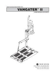
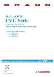
Hand-Held<br />
Attendant's<br />
Control Box<br />
Pump<br />
Module<br />
(Rear)<br />
Page 6<br />
Power/Interlock<br />
Indicator Light<br />
FOLD<br />
(IN)<br />
UNFOLD<br />
(OUT)<br />
DOWN UP<br />
Bottom Parallel<br />
Arms (2)<br />
Rotating Pivot<br />
Slide Arms (2)<br />
Lift-Tite<br />
Towers (2)<br />
(Upright Supports)<br />
Latches (2)<br />
Pump Side<br />
Cylinder<br />
Platform Pivot Arms (2)<br />
Pump Side Vertical Arm<br />
Base<br />
Plate<br />
Automatic<br />
Inboard Roll<br />
Stop and Bridge<br />
Plate<br />
Roll Stop Cylinder<br />
(not visible -underside of platform)<br />
Platform Side Plates (2)<br />
Roll Stop Latch<br />
Top Parallel Arms (2)<br />
Opposite Pump Side Cylinder<br />
Unfold Assist Compression Springs (2)<br />
TM<br />
Adjustable Quiet-Ride Stow Blocks (2)<br />
Platform<br />
Opposite Pump Side Vertical Arm<br />
Vertical Arm Covers (4)<br />
Handrails (2) Note: Handrail<br />
shape varies with lift model.<br />
Automatic Inboard<br />
Roll Stop "IB"<br />
Lift Terminology<br />
Illustration<br />
Inboard<br />
Left (Rear)<br />
Right (Front)<br />
Outboard<br />
Automatic Outboard<br />
Roll Stop (ARS)
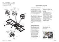
Hand-Held<br />
Attendant's<br />
Control Box<br />
Power/Interlock<br />
Indicator Light<br />
Pump<br />
Module<br />
(Rear)<br />
FOLD<br />
(IN)<br />
UNFOLD<br />
(OUT)<br />
Bottom Parallel<br />
Arms (2)<br />
DOWN UP<br />
Rotating Pivot<br />
Slide Arms (2)<br />
Lift-Tite<br />
Towers (2)<br />
(Upright Supports)<br />
Latches (2)<br />
Pump Side<br />
Cylinder<br />
Platform Pivot Arms (2)<br />
Pump Side Vertical Arm<br />
Base<br />
Plate<br />
Independent<br />
Hinged<br />
Bridge Plate<br />
Roll Stop Cylinder<br />
(not visible -underside of platform)<br />
Platform Side Plates (2)<br />
Roll Stop Latch<br />
Top Parallel Arms (2)<br />
Opposite Pump Side Cylinder<br />
Unfold Assist Compression Springs (2)<br />
Adjustable Quiet-Ride Stow Blocks (2)<br />
Platform<br />
Opposite Pump Side Vertical Arm<br />
Fixed Inboard<br />
Roll Stop<br />
UHMW<br />
Platform<br />
Slides<br />
Vertical Arm Covers (4)<br />
Handrails (2) Note: Handrail<br />
shape varies with lift model.<br />
Fixed Inboard<br />
Roll Stop "Non-IB"<br />
Lift Terminology<br />
Illustration<br />
Inboard<br />
Left (Rear)<br />
Right (Front)<br />
Outboard<br />
Automatic Outboard<br />
Roll Stop (ARS)<br />
Page 7
Safety Symbols<br />
SAFETY FIRST! Know That....<br />
A<br />
Page 8<br />
All information contained<br />
Lift Operation Safety<br />
in this manual and B WARNING<br />
supplements (if included), is<br />
provided for your safety. Familiarity<br />
with proper operation<br />
instructions as well as proper<br />
maintenance procedures are<br />
necessary to ensure safe,<br />
troublefree operation. Safety<br />
precautions are provided to<br />
identify potentially hazardous<br />
situations and provide instruction<br />
on how to avoid them.<br />
This symbol indicates<br />
important safety<br />
information regarding<br />
a potentially hazardous<br />
situation that<br />
could result in serious<br />
bodily injury and/or<br />
property damage.<br />
D Note: Additional information provided to help clarify or detail a specific subject.<br />
C CAUTION<br />
This symbol indicates<br />
important information<br />
regarding how to<br />
avoid a hazardous<br />
situation that could<br />
result in minor personal<br />
injury or property<br />
damage.<br />
These symbols will appear throughout this manual as well as on the labels posted on your lift. Recognize<br />
the seriousness of this information.
Lift Operation Safety Precautions<br />
WARNING<br />
If the lift operating<br />
instructions, manual<br />
operating instructions<br />
and/or lift operation<br />
safety precautions are<br />
not fully understood,<br />
contact The <strong>Braun</strong><br />
<strong>Corporation</strong> immediately.<br />
Failure to do so<br />
may result in serious<br />
bodily injury and/or<br />
property damage.<br />
WARNING<br />
WARNING<br />
Lift Operation Safety<br />
WARNING<br />
WARNING<br />
WARNING<br />
WARNING<br />
Read manual and supplement(s) before operating lift. Read<br />
and become familiar with all safety precautions, pre-lift<br />
operation notes and details, operating instructions and<br />
manual operating instructions before operating the lift. Note:<br />
Wheelchair passengers and all transit agency personnel<br />
(drivers and wheelchair lift attendants) must read and<br />
become familiar with the contents of this manual and<br />
supplement(s) before operation.<br />
Load and unload on level surface only.<br />
Engage vehicle parking brake before operating lift.<br />
Provide adequate clearance outside the vehicle to accommodate<br />
the lift before opening lift door(s) or operating lift.<br />
Inspect lift before operation. Do not operate lift if you suspect lift damage, wear or any<br />
abnormal condition.<br />
Keep operator and bystanders clear of area in which the lift operates.<br />
Page 9
Lift Operation Safety Precautions (continued)<br />
Page 10<br />
WARNING<br />
If the lift operating<br />
instructions, manual<br />
operating instructions<br />
and/or lift operation<br />
safety precautions are<br />
not fully understood,<br />
contact The <strong>Braun</strong><br />
<strong>Corporation</strong> immediately.<br />
Failure to do so<br />
may result in serious<br />
bodily injury and/or<br />
property damage.<br />
WARNING<br />
WARNING<br />
Lift Operation Safety<br />
WARNING Whenever a wheelchair passenger (or standee) is on the<br />
platform, the:<br />
• Passenger must be positioned fully inside yellow<br />
boundaries<br />
• Wheelchair brakes must be locked<br />
• Roll stops must be up (vertical)<br />
• Roll stop latch must be fully engaged<br />
• Passenger should grip both handrails (if able).<br />
WARNING<br />
WARNING<br />
WARNING<br />
Load and unload clear of vehicular traffic.<br />
Do not overload or abuse. The load rating applies to both<br />
the raising and lowering functions - continuous lifting capacity<br />
is 800 lbs.<br />
Do not operate or board the lift if you or your lift operator are<br />
intoxicated.<br />
Do not raise front wheelchair wheels (pull wheelie) when loading (boarding) the platform.<br />
Open lift door(s) fully and secure before operating lift.
WARNING<br />
WARNING<br />
WARNING<br />
WARNING<br />
WARNING<br />
WARNING<br />
WARNING<br />
WARNING<br />
Lift Operation Safety<br />
Position and secure (buckle, engage, fasten, etc.) the wheelchair-equipped occupant seat<br />
belt (torso restraint) before loading onto the wheelchair lift platform.<br />
Lift attendants must ensure that lift occupants keep hands, arms and all other body parts<br />
within the lift occupant area and clear of moving parts.<br />
Platform must be positioned at floor level (bridge plate height) when loading or unloading<br />
in and out of vehicle.<br />
Do not use platform roll stops as a barrier (brake). Stop and brake wheelchair when<br />
loading onto the platform (manually stop and brake manual wheelchairs — stop powered<br />
wheelchairs with the wheelchair controls).<br />
Turn powered (electric) wheelchairs off when on lift platform.<br />
Press the DOWN switch until the entire platform rests on ground level (lowered fully) and<br />
the outboard roll stop is fully unfolded (ramp position) before loading or unloading a<br />
passenger at ground level.<br />
Outboard platform roll stop must be fully unfolded (ramp position) until front and rear<br />
wheelchair wheels cross roll stop when loading or unloading at ground level.<br />
Accidental activation of control switch(es) may cause unintended operation(s).<br />
Page 11
Lift Operation Safety Precautions (continued)<br />
Page 12<br />
WARNING<br />
WARNING<br />
If the lift operating<br />
instructions, manual<br />
operating instructions<br />
and/or lift operation<br />
safety precautions are<br />
not fully understood,<br />
contact The <strong>Braun</strong><br />
<strong>Corporation</strong> immediately.<br />
Failure to do so<br />
may result in serious<br />
bodily injury and/or<br />
property damage.<br />
Lift Operation Safety<br />
WARNING Maintenance and lubrication procedures must be performed<br />
as specified in this manual by authorized (certified) service<br />
personnel.<br />
WARNING<br />
WARNING<br />
WARNING<br />
WARNING<br />
WARNING<br />
WARNING<br />
Replace missing, worn or illegible decals.<br />
Keep owner’s (operator's) manual in lift-mounted manual<br />
storage pouch at all times.<br />
Never modify (alter) a <strong>Braun</strong> <strong>Corporation</strong> lift.<br />
Do not use accessory devices not authorized by The <strong>Braun</strong><br />
<strong>Corporation</strong>.<br />
Do not remove any guards or covers.<br />
Keep clear of any hydraulic leak.<br />
Failure to follow these safety precautions may result in serious bodily injury and/or property<br />
damage.
WARNING<br />
Read and become<br />
familiar with all lift<br />
operation safety<br />
precautions, pre-lift<br />
operation notes and<br />
details, operating<br />
instructions and<br />
manual operating<br />
instructions prior to<br />
operating the lift. If<br />
this information is not<br />
fully understood,<br />
contact The <strong>Braun</strong><br />
<strong>Corporation</strong> immediately.<br />
Failure to do so<br />
may result in serious<br />
bodily injury and/or<br />
property damage.<br />
Pre-Lift Operation Notes and Details<br />
L915 <strong>Series</strong> lift models are<br />
specifically designed to be operated<br />
by an attendant. The Lift<br />
Operating Instructions contained<br />
in this manual and posted on the<br />
lift provide instructions for operation<br />
of the lift only. Read and<br />
become familiar with all lift operation<br />
safety precautions, pre-lift<br />
operation notes and details,<br />
operating instructions and manual<br />
operating instructions before<br />
attempting lift operation procedures.<br />
Lift Access Doors and Lift<br />
Interlocks: Attendants must<br />
become familiar with the vehicle<br />
lift access door system and the<br />
interlock system (if equipped), as<br />
well as the proper operation of the<br />
lift. Transit vehicles and lift access<br />
door configurations vary. Door<br />
securement devices (latches,<br />
hooks, cables, etc.) and procedures<br />
to operate them vary also.<br />
Lift interlocks are required by<br />
nearly all transit authorities.<br />
Instructions for operation of<br />
interlocks and door securement<br />
systems cannot be addressed in<br />
this manual or on lift-posted<br />
operating instructions decals due<br />
to the variety of procedures<br />
required for operating them.<br />
It is the responsibility of the lift<br />
operator (attendant) to properly<br />
open, secure and close the<br />
vehicle lift door(s), to activate the<br />
lift interlock (if equipped), to load<br />
and unload the wheelchair<br />
passenger (or standee) on and off<br />
the lift platform, and to properly<br />
activate all lift functions.<br />
Page 13
General Safety: The lift operator (attendant)<br />
and bystanders must keep clear of the area in<br />
which the lift operates and clear of all moving<br />
parts. Lift attendants must ensure that lift<br />
Lift Control Switches<br />
The hand-held attendant’s control box provides<br />
an orange UNFOLD/FOLD (Out/In) switch and<br />
a red DOWN/UP switch. The control switches<br />
are color-coded to correspond to the color<br />
coding and switch function labels that appear<br />
on the lift-posted operating instructions decal.<br />
Triangular-shaped color-coded symbols ( )<br />
appear on the lift operating instructions decal.<br />
The color of the symbol corresponds to the<br />
color of the corresponding switch. The direction<br />
(point) of the symbol corresponds with the<br />
direction the switch should be pressed (activated)<br />
to produce the intended lift function.<br />
Page 14<br />
Pre-Lift Operation Notes and Details<br />
occupants (passengers) keep hands, arms and all<br />
other body parts within the lift occupant area and<br />
clear of moving parts.<br />
Press<br />
switch<br />
left for<br />
UNFOLD<br />
(Out)<br />
Press<br />
switch<br />
left for<br />
DOWN<br />
(To Lower)<br />
Orange OUT/IN Switch<br />
Red DOWN/UP Switch<br />
Press<br />
switch<br />
right for<br />
FOLD<br />
(In)<br />
Press<br />
switch<br />
right for<br />
UP<br />
(To Raise)
Lift Features<br />
Become familiar with all lift<br />
features and the proper operation<br />
of the lift components<br />
before attempting lift operation.<br />
Refer to the Lift Terminology<br />
Illustrations for identification of<br />
specific lift components if not<br />
WARNING<br />
Discontinue lift use<br />
immediately if any lift<br />
component does not<br />
operate properly.<br />
Failure to do so may<br />
result in serious<br />
bodily injury and/or<br />
property damage.<br />
Pre-Lift Operation Notes and Details<br />
clearly depicted in this section.<br />
Contact The <strong>Braun</strong> <strong>Corporation</strong> at<br />
1-800-THE LIFT immediately if<br />
any of this information is not<br />
understood.<br />
Latch<br />
Engagement<br />
Pin (Roller)<br />
Engaged<br />
Lift-Tite <br />
Latch<br />
Lift-Tite Latches: <strong>Series</strong> A4<br />
and newer Millennium lift Models<br />
are equipped with Lift-Tite <br />
Latches. Lift-Tite Latches<br />
prevent the platform from unfold-<br />
Page 15
Lift Features (continued)<br />
ing from the stowed position in<br />
the event of platform drift. Due to<br />
the “all-hydraulic” operation of the<br />
dual-cylinder L915, hydraulic fluid<br />
expansion, contraction or seepage<br />
may occur. Any of these<br />
conditions may result in platform<br />
drift (failure to hold the platform in<br />
the folded or raised position).<br />
Platform drift may occur during lift<br />
shipment and/or between extended<br />
periods of non-lift use.<br />
In the event that the platform<br />
does not unfold when the<br />
UNFOLD switch is pressed,<br />
press the FOLD switch momentarily<br />
to disengage the Lift-Tite <br />
latches (platform drift has<br />
occurred). Then, press the<br />
Page 16<br />
Pre-Lift Operation Notes and Details<br />
UNFOLD switch to unfold the<br />
platform to floor level (standard<br />
operation).<br />
When manually operating a lift<br />
equipped with Lift-Tite latches,<br />
Disengaged<br />
Lift-Tite <br />
Latch<br />
Latch<br />
Engagement<br />
Pin (Roller)<br />
insert the pump handle in the<br />
pump and stroke until the platform<br />
folds fully (stops). Then,<br />
open the hand pump valve (turn<br />
counterclockwise) to unfold the<br />
platform.
Folding the platform fully first will<br />
ensure that the Lift-Tite latches<br />
will disengage properly when<br />
the release valve is opened (in<br />
event of platform drift). Manual<br />
Operating Instructions are<br />
provided on pages 32-36.<br />
WARNING<br />
Discontinue lift use<br />
immediately if any lift<br />
component does not<br />
operate properly.<br />
Failure to do so may<br />
result in serious<br />
bodily injury and/or<br />
property damage.<br />
Pre-Lift Operation Notes and Details<br />
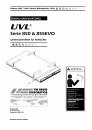
Bridge Plates and Inboard<br />
Roll Stops: L915 <strong>Series</strong> lift<br />
models are available with an<br />
automatic inboard roll stop that<br />
also serves as the bridge plate<br />
(“IB” lift models), or a combination<br />
stationary inboard roll stop<br />
and an independent hinged<br />
bridge plate (“non-IB” lift<br />
models). An “IB” lift model is<br />
depicted in the Lift Terminology<br />
Illustration on page 6.<br />
Automatic Inboard Roll Stop<br />
and Bridge Plate: L915 “IB” lift<br />
models are equipped with an<br />
automatic inboard roll stop that<br />
also serves as the bridge plate<br />
(automatic inboard roll stop<br />
photos on page 18).<br />
When the UNFOLD switch is<br />
pressed and the platform unfolds<br />
from stow position to floor level,<br />
this mechanical roll stop/bridge<br />
plate is automatically deployed to<br />
the bridging (horizontal) position<br />
to provide a bridge plate between<br />
the platform and the lift base plate<br />
(vehicle floor). The inboard edge<br />
of the bridge plate rests on the lift<br />
base plate.<br />
The mechanical roll stop/bridge<br />
plate automatically folds (rotates)<br />
to the vertical (roll stop) position<br />
when the platform lowers to the<br />
ground (DOWN switch is<br />
pressed).<br />
As the UP switch is pressed and<br />
the platform raises from ground<br />
level, the roll stop automatically<br />
unfolds (rotates) to the horizontal<br />
Page 17
Lift Features (continued)<br />
(bridging) position when it<br />
reaches vehicle floor level. The<br />
roll stop must overlap the lift base<br />
plate a minimum 1/2".<br />
When the FOLD switch is<br />
pressed and the platform folds<br />
from floor level to the stow<br />
Page 18<br />
Pre-Lift Operation Notes and Details<br />
(vertical) position, the roll stop/<br />
bridge plate automatically travels<br />
inboard to the stowed position.<br />
Read warning posted on<br />
opposite page. Discontinue lift<br />
operation immediately if the<br />
roll stop does not operate<br />
properly.<br />
Fully-Folded<br />
(vertical)<br />
Inboard<br />
Roll Stop<br />
Fully-Unfolded<br />
(horizontal)<br />
Inboard Roll Stop<br />
(bridging position)<br />
Automatic Inboard Roll<br />
Stop and Bridge Plate “IB”<br />
The inboard roll stop “IB”<br />
must overlap the base<br />
plate a minimum 1/2".<br />
Fixed Inboard Roll Stop: A<br />
stationary inboard roll stop is built<br />
into “non-IB” L915 lift platforms<br />
(shown in left-hand photo on<br />
page 19).<br />
Independent Hinged Bridge<br />
Plate: “Non-IB” L915 lift models<br />
are equipped with an independent<br />
hinged bridge plate (shown in
photo below right). The bridge<br />
plate bridges the gap between the<br />
platform and the lift base plate<br />
when the platform is fully raised<br />
(at floor level), providing a surface<br />
for wheelchair travel.<br />
The bridge plate unfolds (rotates)<br />
to the horizontal position (rests on<br />
Pre-Lift Operation Notes and Details<br />
platform) when the platform<br />
unfolds from stow position to floor<br />
level (UNFOLD switch is<br />
pressed).<br />
The bridge plate folds (rotates) to<br />
the vertical position when the<br />
platform folds (FOLD switch is<br />
pressed).<br />
Bridge plate at floor level.<br />
Fixed Inboard Roll<br />
Stop “non-IB”<br />
Independent Hinged<br />
Bridge Plate<br />
WARNING<br />
Discontinue lift use<br />
immediately if any lift<br />
component does not<br />
operate properly.<br />
Failure to do so may<br />
result in serious<br />
bodily injury and/or<br />
property damage.<br />
Page 19
Lift Features (continued)<br />
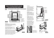
Automatic Outboard Roll Stop<br />
(ARS): This cylinder-powered roll<br />
stop provides a ramp for wheelchair<br />
loading and unloading at<br />
ground level (see photos below).<br />
When the platform lowers fully to<br />
ground level, the cylinder com-<br />
Page 20<br />
Fully-Engaged Roll Stop Latch<br />
Latch Foot<br />
Pre-Lift Operation Notes and Details<br />
2"<br />
pression spring automatically<br />
unfolds (rotates) the roll stop to<br />
the ramp position (fully unfolded).<br />
Although the outboard roll stop is<br />
lift-powered, the activation of the<br />
roll stop is controlled by the lift<br />
operator (attendant). Pressing<br />
the DOWN switch deploys<br />
Outboard Roll Stop<br />
Fully-Folded<br />
Roll Stop<br />
(Up-vertical)<br />
Disengaged<br />
Roll Stop<br />
Latch<br />
Note: Platform must raise<br />
approximately two inches<br />
before latch engages fully.<br />
(unfolds) the roll stop. The roll<br />
stop is cylinder-powered to<br />
automatically fold (rotate) to the<br />
vertical position as shown when<br />
the UP switch is pressed (roll stop<br />
raises before platform raises).<br />
Discontinue lift operation<br />
immediately if the roll stop<br />
does not operate properly.<br />
Fully-Unfolded Roll Stop (Ramp position)
Roll Stop Latch: A springloaded<br />
latch engages the outboard<br />
roll stop when the roll stop<br />
rotates upward from ramp position<br />
to the vertical position (UP<br />
switch is pressed to raise the<br />
platform above ground level).<br />
Note: The platform must raise<br />
approximately two inches before<br />
the latch engages fully (see<br />
photos on previous page).<br />
The latch disengages the roll stop<br />
when the platform lowers fully<br />
(reaches ground level) and the<br />
latch foot contacts the ground<br />
(latch raises above the roll stop).<br />
Outboard Roll Stop and Roll<br />
Stop Latch Operation: The lift<br />
operator (attendant) must press<br />
the DOWN switch to lower the<br />
Pre-Lift Operation Notes and Details<br />
platform fully to the ground. The<br />
attendant must view the platform<br />
as it lowers to be certain the<br />
entire platform reaches and<br />
rests safely on the ground. Stop<br />
pressing the DOWN switch if any<br />
portion of the platform is obstructed<br />
while descending or the<br />
entire platform does not reach<br />
ground level for any reason<br />
(contact with an obstruction,<br />
mechanical failure, exceeding the<br />
lift “floor-to-ground” capacity,<br />
etc.).<br />
After the platform is fully lowered<br />
(entire platform reaches the<br />
ground), the attendant should<br />
continue to press the DOWN<br />
switch to unfold the outboard roll<br />
stop fully (ramp position). Note:<br />
The roll stop must be fully<br />
unfolded until the entire wheelchair<br />
(or standee) has crossed<br />
the roll stop when loading or<br />
unloading at ground level.<br />
Discontinue lift operation<br />
immediately if the roll stop or<br />
latch do not operate properly.<br />
Bridging: The L915 incorporates<br />
a bridging feature. This<br />
feature stops the down travel of<br />
the platform if the outboard end<br />
of the platform contacts a raised<br />
surface (such as a curb), preventing<br />
the operator from lowering<br />
the inboard end of the<br />
platform.<br />
Handrails: Dual handrails are<br />
provided for wheelchair passenger<br />
(or standee) use. The<br />
handrails unfold automatically to<br />
Page 21
Lift Features (continued)<br />
the deployed (horizontal) position<br />
when the lift unfolds and automatically<br />
fold to the stowed<br />
(vertical) position when the<br />
platform folds.<br />
Passengers should grip both<br />
handrails when on the lift platform<br />
if able. Discontinue lift operation<br />
immediately if the handrails<br />
do not operate properly.<br />
Lift Passengers<br />
If you are an attendant operating<br />
the lift, it is your responsibility to<br />
perform safe loading and unloading<br />
procedures. Wheelchair lift<br />
attendants should be instructed<br />
on any special needs and/or<br />
Page 22<br />
Pre-Lift Operation Notes and Details<br />
procedures required for safe<br />
transport of wheelchair passengers.<br />
The lift operator and bystanders<br />
must keep clear of the area in<br />
which the lift operates. Observe<br />
your passenger at all times during<br />
lift operation.<br />
Do not attempt to load or unload<br />
a passenger in a wheelchair or<br />
other apparatus that does not fit<br />
on the platform area. Do not<br />
exceed the 800 pound load<br />
capacity of the lift. The lift<br />
attendant should not ride on the<br />
platform with the passenger.<br />
Passenger Orientation (Boarding<br />
Direction): <strong>Braun</strong> L915<br />
<strong>Series</strong> ADA wheelchair lifts fully<br />
comply with the ADA requirement<br />
that the lift accommodate<br />
both inboard and outboard facing<br />
wheelchair passengers or<br />
standees. Inboard facing of<br />
wheelchair lift passengers is not<br />
prohibited, but outboard facing<br />
of passengers is recommended<br />
by The <strong>Braun</strong> <strong>Corporation</strong>.<br />
<strong>Braun</strong> L915 <strong>Series</strong> ADA certified<br />
lifts permit both inboard and<br />
outboard facing of wheelchair and<br />
mobility aid users and accommodate<br />
persons using walkers,<br />
crutches, canes or braces or who<br />
otherwise have difficulty using<br />
steps as specified in Americans<br />
With Disabilities Act (ADA)<br />
Accessibility Specifications For<br />
Transportation Vehicles-Part 38.
Standees: Lift Operating Instructions<br />
apply to wheelchair passengers<br />
and standees. Standees<br />
should stand in the center of the<br />
platform (fully inside the yellow<br />
boundaries) and grip both<br />
handrails (if able) when on platform.<br />
Yellow Boundaries: The passenger<br />
must be positioned in the<br />
center of the platform to prevent<br />
side-to-side load imbalance. The<br />
lift attendant (operator) should not<br />
ride on the platform with the<br />
passenger.<br />
Yellow platform loading boundaries<br />
are identified in the following<br />
manner. Yellow plastic edge liner<br />
(u-molding) is positioned on<br />
platform side plates of all lift<br />
Pre-Lift Operation Notes and Details<br />
models. Yellow edge liner is<br />
positioned on fixed inboard roll<br />
stops also. Yellow plastic caps are<br />
placed on the dual handrails.<br />
A yellow boundary strip decal is<br />
affixed to extruded aluminum<br />
outboard roll stops. Yellow antiskid<br />
is affixed to nonextruded steel<br />
outboard roll stops. A yellow<br />
boundary strip decal is affixed to<br />
the inboard end (heel) of the<br />
platform (automatic inboard roll stop<br />
“IB” lift models). Yellow antiskid is<br />
affixed to the outboard edge of<br />
independent hinged bridge plates<br />
(“non-IB” lift models).<br />
The attendant must always be<br />
certain the wheelchair passenger or<br />
standee is properly positioned on<br />
the platform (fully inside yellow<br />
boundaries) and the wheelchair<br />
brakes are locked when a passenger<br />
is on the lift platform. The lift<br />
passenger must keep hands,<br />
arms and all other body parts<br />
within the lift occupant area and<br />
clear of all moving parts.<br />
Vehicle (Floor Level) Loading<br />
and Unloading: The platform<br />
must be fully raised (at floor level)<br />
and the bridge plate must be<br />
properly positioned when loading<br />
or unloading passengers in or out<br />
of the vehicle. It is the responsibility<br />
of the lift operator (attendant)<br />
to ensure the platform<br />
and the bridge plate are properly<br />
positioned at floor level<br />
when loading and unloading<br />
passengers.<br />
Page 23
Lift Passengers (continued)<br />
Page 24<br />
WARNING<br />
Whenever a<br />
passenger is on the<br />
platform, the:<br />
• Passenger must be<br />
positioned fully<br />
inside yellow<br />
boundaries<br />
• Wheelchair brakes<br />
must be locked<br />
• Roll stop(s) must be<br />
UP<br />
Failure to follow these<br />
rules may result in<br />
serious bodily injury<br />
and/or property<br />
damage.<br />
Pre-Lift Operation Notes and Details<br />
The wheelchair brakes must be<br />
locked, the outboard roll stop<br />
must be in the fully-up (vertical)<br />
position and the roll stop latch<br />
must be fully engaged whenever<br />
a passenger is on the platform.<br />
Do not use the outboard roll stop<br />
as a barrier (brake). Stop and<br />
brake the wheelchair when fully<br />
loaded on the platform. Manually<br />
stop and brake manual wheelchairs.<br />
Stop powered wheelchairs<br />
with the wheelchair controls. Turn<br />
powered (electric) wheelchairs off<br />
when on the platform.<br />
If the roll stop, bridge plate,<br />
handrails or any other lift component<br />
does not operate as outlined<br />
in this manual, discontinue<br />
lift use immediately and contact<br />
The <strong>Braun</strong> <strong>Corporation</strong> sales<br />
WARNING<br />
Discontinue lift use<br />
immediately if any lift<br />
component does not<br />
operate properly.<br />
Failure to do so may<br />
result in serious<br />
bodily injury and/or<br />
property damage.<br />
representative in your area or<br />
call The <strong>Braun</strong> <strong>Corporation</strong> at<br />
1-800-THE LIFT. One of our<br />
national Product Support<br />
representatives will direct you to<br />
an authorized service technician<br />
who will inspect your lift.
Wheelchair-Equipped<br />
Occupant Seat Belts<br />
The <strong>Braun</strong> <strong>Corporation</strong> recommends<br />
wheelchair passengers<br />
position and buckle their wheel-<br />
WARNING<br />
Position and secure<br />
(buckle, engage,<br />
fasten, etc.) the<br />
wheelchair-equipped<br />
occupant seat belt<br />
before loading onto<br />
the wheelchair lift<br />
platform. Failure to<br />
do so may result in<br />
serious bodily injury<br />
and/or property<br />
damage.<br />
Pre-Lift Operation Notes and Details<br />
chair-equipped seat belt (torso<br />
restraint) before loading onto a<br />
wheelchair lift.<br />
Different types of disabilities<br />
require different types of wheelchairs<br />
and different types of<br />
wheelchair-equipped occupant<br />
restraint belt systems (torso<br />
restraints). It is the responsibility<br />
of the wheelchair passenger to<br />
have his or her wheelchair<br />
equipped with an occupant<br />
restraint (seat belt) under the<br />
direction of their health care<br />
professional.<br />
Wheelchair lift attendants should<br />
be instructed on any special<br />
needs and/or procedures required<br />
for safe transport of<br />
wheelchair passengers.<br />
Operation Procedure Review<br />
The <strong>Braun</strong> <strong>Corporation</strong> recommends<br />
that transit agency supervisors<br />
and wheelchair lift attendants<br />
review the safety precautions<br />
and operation procedures<br />
appearing in this manual and on<br />
lift-posted decals with your<br />
wheelchair lift sales representative<br />
(dealer), before attempting<br />
lift operation.<br />
Any questions or concerns can be<br />
answered by the sales representative<br />
at that time. Operate the lift<br />
through all functions with your<br />
sales representative on hand to<br />
ensure the proper use and<br />
operation of the wheelchair lift is<br />
understood.<br />
Page 25
Transit agency supervisors<br />
should train and educate their lift<br />
attendants on the proper use and<br />
operation of the wheelchair lift if it<br />
is not possible for the attendants<br />
to review the safety precautions<br />
Page 26<br />
WARNING<br />
Maintenance and<br />
lubrication procedures<br />
must be performed<br />
by authorized<br />
service personnel as<br />
specified in the<br />
applicable installation/service<br />
manual.<br />
Failure to do so may<br />
result in serious<br />
bodily injury and/or<br />
property damage.<br />
Pre-Lift Operation Notes and Details<br />
and operation procedures with<br />
the wheelchair lift sales representative.<br />
The lift owner's (operator's)<br />
manual must be stored in the<br />
lift-mounted manual storage<br />
pouch at all times.<br />
Preventive Maintenance:<br />
Maintenance is necessary to<br />
ensure safe and troublefree lift<br />
operation. General preventive lift<br />
maintenance consisting of<br />
careful inspections of the lift<br />
system and cleaning the lift<br />
should be a part of your transit<br />
agency's daily lift service program.<br />
Simple inspections can<br />
detect potential lift operational<br />
problems.<br />
Regular preventive maintenance<br />
will reduce potential lift operation<br />
downtime and increase the<br />
service life of the lift, as well as<br />
possibly detecting potential<br />
hazards.<br />
Exposure to harsh weather<br />
elements, environmental conditions,<br />
or heavy usage may require<br />
more frequent maintenance and<br />
lubrication procedures.<br />
Preventive maintenance visual<br />
inspections do not take the place<br />
of the procedures specified in the<br />
Maintenance and Lubrication<br />
Schedule provided in the applicable<br />
lift installation and service<br />
manual. Refer to the Maintenance<br />
and Lubrication section in<br />
this manual for further details.
WARNING<br />
Read and become<br />
familiar with all lift<br />
operation safety<br />
precautions, pre-lift<br />
operation notes and<br />
details, operating<br />
instructions and<br />
manual operating<br />
instructions prior to<br />
operating the lift. If<br />
this information is not<br />
fully understood,<br />
contact The <strong>Braun</strong><br />
<strong>Corporation</strong> immediately.<br />
Failure to do so<br />
may result in serious<br />
bodily injury and/or<br />
Lift Operating Instructions<br />
WARNING<br />
Whenever a<br />
passenger is on the<br />
platform, the:<br />
• Passenger must be<br />
positioned fully<br />
inside yellow<br />
boundaries<br />
• Wheelchair brakes<br />
must be locked<br />
• Roll stop(s) must be<br />
UP<br />
Failure to follow these<br />
rules may result in<br />
serious bodily injury<br />
and/or property<br />
damage.<br />
Lift Operating Instructions photos<br />
depict an L915 “IB” <strong>Series</strong> lift<br />
model. Instructions and procedures<br />
are applicable for all L915<br />
<strong>Series</strong> lift models.<br />
Refer to the Lift Terminology<br />
Illustrations and the photos<br />
appearing in the Pre-Lift Operating<br />
Notes and Details section for<br />
identification of lift components.<br />
Contact The <strong>Braun</strong> <strong>Corporation</strong><br />
immediately if not understood<br />
(call 1-800-THE LIFT).<br />
Follow the Manual Operating<br />
Instructions provided on pages<br />
32-36 in event of power or<br />
equipment failure.<br />
property damage. Note: Engage vehicle parking<br />
brake before operating lift.<br />
Page 27
Page 28<br />
Lift Operating Instructions<br />
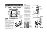
Open Door(s) and Secure<br />
To Unfold Platform (Out):<br />
Stand clear and press the orange<br />
UNFOLD (Out) switch until the<br />
platform stops (reaches floor level<br />
- unfolds fully). Release switch.<br />
Note: In event platform does not<br />
unfold, press FOLD switch to<br />
release Lift-Tite latches.<br />
To Unload Passenger:<br />
1. Read Note below! Load passenger<br />
onto platform and lock wheelchair<br />
brakes.<br />
Note: Passenger must be positioned<br />
fully inside yellow<br />
boundaries, outboard roll stop<br />
must be UP and roll stop latch<br />
must be engaged.
A<br />
C<br />
Lift Operating Instructions<br />
To Unload Passenger (continued):<br />
2. Press red DOWN switch until the<br />
entire platform reaches ground<br />
level (see Photo B) and the<br />
outboard roll stop unfolds fully<br />
(ramp position). See Photo C.<br />
Release switch.<br />
3. Unlock wheelchair brakes and<br />
unload passenger from platform.<br />
Note: Roll stop must be fully<br />
unfolded (ramp position) until the<br />
entire wheelchair (or standee) has<br />
crossed the roll stop. See Photos<br />
E and F on page 30 also.<br />
B<br />
D<br />
Page 29
E<br />
G<br />
Page 30<br />
Lift Operating Instructions<br />
To Load Passenger:<br />
1. Read Notes below! Load passenger<br />
onto platform and lock<br />
wheelchair brakes. See Photo G.<br />
Note: Roll stop must be fully<br />
unfolded (ramp position) until the<br />
entire wheelchair (or standee) has<br />
crossed the roll stop. See Photos<br />
E and F.<br />
Note: Passenger must be<br />
positioned fully inside yellow<br />
boundaries.<br />
F<br />
H
I To Load Passenger (continued):<br />
J<br />
K<br />
Lift Operating Instructions<br />
2. Press red UP switch (Photo I) to fold<br />
outboard roll stop UP fully (vertical -<br />
see Photo H), and raise the platform<br />
to floor level. See Photo J. Release<br />
switch.<br />
3. Unlock wheelchair brakes and unload<br />
passenger from platform.<br />
To Fold Platform (In):<br />
Press orange FOLD (In) switch until<br />
platform stops (fully folded). See<br />
Photos K and L. Release switch.<br />
Close Door(s)<br />
L<br />
Page 31
If you experience power or<br />
equipment failure, refer to the<br />
Manual Operating Instructions to<br />
operate the lift. Instructions and<br />
photos are provided for all steps<br />
Turn wing 1/4 turn.<br />
Lock<br />
Page 32<br />
Unlock<br />
Manual Operating Instructions<br />
Pump<br />
Cover<br />
that differ from standard lift<br />
operation procedures. Manual<br />
Instructions Decal #29082<br />
(posted inside pump cover)<br />
provides manual operating<br />
Hand<br />
Pump<br />
Handle<br />
instructions also. Note: A rear<br />
pump lift model is depicted in the<br />
photos. Front pump applications are<br />
a mirrored image. Refer to the Lift<br />
Operating Instructions for all normal<br />
Rotate top clip to access handle.
lift operation procedures (such as<br />
loading and unloading passengers).<br />
Follow all Lift Operation<br />
Safety Precautions!<br />
A<br />
Manual Operating Instructions<br />
Hand Pump<br />
Remove the pump cover to gain<br />
access to the pump handle and<br />
the hand pump. See photos on<br />
page 32. To remove the pump<br />
cover, turn the wing nut located<br />
Release Valve<br />
Note: Close backup pump release valve<br />
securely before operating electric pump.<br />
on top 1/4 turn and lift the pump<br />
cover off. The pump handle is<br />
inside this cover secured by two<br />
clips. Rotate the top clip to<br />
remove the pump handle.<br />
maximum<br />
30 inch lbs<br />
minimum<br />
15 inch lbs<br />
seats<br />
(stops)<br />
approximate<br />
1/16" intervals<br />
OPEN<br />
CLOSE<br />
Release Valve<br />
Valve Tightening<br />
Specification:<br />
Once valve seats<br />
(stops), tighten 15<br />
to 30 inch pounds<br />
as shown.<br />
Page 33
Remove pump cover to access<br />
hand pump and pump handle as<br />
outlined on page 32. Refer to<br />
release valve photos and illustration<br />
on page 33.<br />
Page 34<br />
Open<br />
(Down)<br />
Close<br />
(Up/Stop)<br />
Manual Operating Instructions<br />
To Unfold Platform (Out):<br />
Using hand pump handle (Photo B):<br />
1. Close hand pump valve (place<br />
slotted end of pump handle onto<br />
backup pump release valve and<br />
turn clockwise).<br />
2. Insert handle in pump and stroke<br />
until platform folds fully (stops).<br />
3. Open hand pump valve (turn<br />
counterclockwise) until platform<br />
reaches floor level. Open 1/2<br />
turn only.<br />
4. Close hand pump valve (turn<br />
clockwise).<br />
Note: Valve must be tight, but do<br />
not overtighten.<br />
DOWN<br />
• To Lower Platform:<br />
• To Unfold Roll Stop:<br />
onto backup pump release valve<br />
and turn counterclockwise (open<br />
— 1/2 turn only) until the platform<br />
reaches ground level and roll stop<br />
unfolds.<br />
Stroking<br />
Hand<br />
Pump<br />
B Place slotted end of pump handle<br />
C
Remove pump cover to access<br />
hand pump and pump handle as<br />
outlined on page 32. Refer to<br />
release valve photos and illustration<br />
on page 33.<br />
D<br />
Open<br />
(Down)<br />
Close<br />
(Up/Stop)<br />
Manual Operating Instructions<br />
UP<br />
• To Fold Roll Stop:<br />
• To Raise Platform:<br />
Using hand pump handle:<br />
1. Place slotted end of pump<br />
handle onto backup pump<br />
release valve and turn clockwise<br />
to close securely. See<br />
Photo D.<br />
Note: Valve must be tight, but<br />
do not overtighten.<br />
2. Insert handle into backup pump<br />
and stroke until platform<br />
reaches floor level (see Photo<br />
E).<br />
To Fold Platform (In):<br />
Insert handle into backup pump<br />
and stroke until platform stops<br />
(folds fully). See Photo E.<br />
Note: Close backup pump<br />
release valve securely before<br />
operating electric pump.<br />
Store pump handle and install<br />
pump cover as outlined on page<br />
36.<br />
Stroking<br />
Hand<br />
Pump<br />
E<br />
Page 35
To Store Pump Handle:<br />
1. Insert bottom of handle behind<br />
bottom clip. See page 32.<br />
2. Rotate top clip to secure (lock)<br />
handle.<br />
Page 36<br />
Manual Operating Instructions<br />
To Install Pump Cover:<br />
1. Position cover over module<br />
back cover. See Photo F.<br />
2. Align outside cover lip with<br />
bottom cover offset and insert<br />
outside cover. See Photo G.<br />
Align and insert bottom of cover.<br />
3. Insert wing stud and rotate 1/4<br />
turn to lock cover. See Photo<br />
H.<br />
Lock<br />
Unlock<br />
F G<br />
H
WARNING<br />
Replace missing, worn<br />
or illegible decals.<br />
Failure to do so may<br />
result in serious bodily<br />
injury and/or property<br />
damage.<br />
Note: Clean surfaces<br />
with isopropyl alcohol<br />
before decal or antiskid<br />
application. Use a clean<br />
cloth or paper towels.<br />
Do not use oily shop<br />
rags. Wipe surface free<br />
of residue with dry<br />
portion of cleaning cloth.<br />
See Decals on page 38 also.<br />
Decals and Antiskid<br />
Decals<br />
The lift is only as safe as the operator.<br />
Replace any missing, worn or<br />
illegible decals! Part numbers are<br />
provided for decals. Inspect your lift for<br />
missing, worn or illegible decals. Call<br />
1-800-THE LIFT for replacements.<br />
25674<br />
WARNING<br />
Oper<br />
Man<br />
ator's<br />
ual<br />
Read manual before<br />
operating lift. Call<br />
1-800-THE LIFT to<br />
receive operator's<br />
manual. Failure to<br />
do so may result in<br />
serious bodily injury<br />
and/or property<br />
damage. Keep<br />
manual in lift pouch.<br />
25674<br />
25675<br />
WARNING<br />
Lift installation and servicing prohibited by<br />
anyone who has not been certified by The <strong>Braun</strong><br />
<strong>Corporation</strong> Sales and Service School. Certified<br />
service technicians should call 1-800-THE LIFT<br />
to receive applicable installation/service manual.<br />
Failure to follow this policy may result in serious<br />
bodily injury and/or property damage.<br />
25675<br />
22249<br />
WARNING<br />
Contact The <strong>Braun</strong><br />
<strong>Corporation</strong> before<br />
adjusting hydraulic<br />
pressure relief<br />
valve. Failure to<br />
do so may result<br />
in serious bodily<br />
injury and/or<br />
property damage. 22249<br />
27154<br />
WARNING<br />
Improper hydraulic<br />
pressure switch<br />
adjustment may result<br />
in serious bodily injury<br />
and/or property damage.<br />
HYDRAULIC<br />
PRESSURE SWITCH<br />
ADJUSTMENT<br />
Adjust switch as specified<br />
in installation/service<br />
manual.<br />
27154<br />
27204<br />
WARNING<br />
• Read manual before operating lift.<br />
• Load and unload on level surface<br />
only.<br />
• Engage vehicle parking brake before<br />
operating lift.<br />
• Provide adequate clearance outside<br />
of vehicle to accommodate lift.<br />
• Do not operate lift if you suspect lift<br />
damage, wear or any abnormal<br />
condition.<br />
• Keep operator and bystanders clear<br />
of area in which lift operates.<br />
Whenever a wheelchair passenger<br />
is on the platform, the:<br />
• Passenger must be positioned<br />
fully inside yellow boundaries<br />
• Wheelchair brakes must be locked<br />
• Roll stop(s) must be up<br />
Failure to follow these rules may result<br />
in serious bodily injury and/or property<br />
damage.<br />
LIFT OPERATING<br />
INSTRUCTIONS<br />
OPEN DOOR(S) AND SECURE<br />
TO UNFOLD PLATFORM:<br />
Stand clear and press UNFOLD<br />
switch until platform stops (reaches<br />
floor level).<br />
Note: In event platform does not<br />
unfold, press FOLD switch to<br />
release Lift-Tite latches.<br />
TO UNLOAD PASSENGER:<br />
1. Load passenger onto platform and<br />
lock wheelchair brakes.<br />
2. Press DOWN switch until entire<br />
platform reaches ground level and<br />
roll stop unfolds fully.<br />
3. Unlock wheelchair brakes and unload<br />
passenger from platform.<br />
TO LOAD PASSENGER:<br />
1. Load passenger onto platform and<br />
lock wheelchair brakes.<br />
2. Press UP switch to fold roll stop<br />
up and raise platform to floor level.<br />
3. Unlock wheelchair brakes and unload<br />
passenger from platform.<br />
TO FOLD PLATFORM:<br />
Press FOLD switch until platform<br />
stops. Release switch.<br />
CLOSE DOOR(S)<br />
U.S. Patent No. 5,261,779 U.S. Patent No. 6,065,924<br />
U.S. Patent No. 5,806,632 Patents Pending<br />
27204<br />
19342<br />
OPERATING<br />
INSTRUCTIONS<br />
Read warnings and operate lift as<br />
outlined on LIFT OPERATING<br />
INSTRUCTIONS decal. Lift operating<br />
instructions apply to wheelchair<br />
passengers and standees.<br />
Standee Instructions: Standees must<br />
stand at center of platform (fully inside<br />
yellow boundaries), grip handrails and<br />
lower head to clear door jamb header.<br />
Interlock Instructions: Lift Interlocks<br />
vary in type and operation. Interlock<br />
(if equipped) must be operated as<br />
instructed by transit authority.<br />
29082<br />
MANUAL OPERATION<br />
TO REMOVE PUMP HANDLE:<br />
1. Rotate top clip.<br />
Using hand pump handle:<br />
TO UNFOLD PLATFORM (OUT):<br />
1. Close hand pump valve<br />
(turn clockwise).<br />
2. Insert handle in pump and<br />
stroke until platform folds<br />
fully (stops).<br />
3. Open hand pump valve (turn<br />
counterclockwise) until<br />
platform reaches floor level.<br />
Open 1/2 turn only.<br />
4. Close hand pump valve<br />
(turn clockwise).<br />
DOWN (TO LOWER):<br />
Open hand pump valve (turn<br />
counterclockwise). Open<br />
1/2 turn only.<br />
OPEN<br />
UP (TO RAISE):<br />
CLOSE<br />
1. Close hand pump valve<br />
(turn clockwise).<br />
2. Insert handle in pump and<br />
stroke until platform reaches<br />
floor level.<br />
TO FOLD PLATFORM (IN):<br />
Insert handle in pump and stroke.<br />
Note: Close valve before operating<br />
electric pump.<br />
TO STORE PUMP HANDLE:<br />
1. Insert bottom of handle<br />
behind bottom clip.<br />
2. Rotate clip to lock.<br />
OPEN<br />
LOCK<br />
VALVE<br />
CLOSE<br />
UNLOCK<br />
19342<br />
29082<br />
Page 37
Replace missing, worn<br />
or illegible decals.<br />
Failure to do so may<br />
result in serious bodily<br />
injury and/or property<br />
damage.<br />
Page 38<br />
WARNING<br />
Note: Clean surfaces as<br />
detailed on opposite page<br />
before posting decals.<br />
See Decals on page 37 also.<br />
Decals and Antiskid<br />
"Providing Access to the World"<br />
International Corporate Hdqrs: P.O. Box 310 Winamac, IN 46996 USA<br />
1-800-THE LIFT (219) 946-6153 FAX: (219) 946-4670<br />
Fairfield, NJ USA<br />
Oslo, Norway<br />
Parking Courtesy<br />
Requested<br />
Clearwater, FL USA Huntington Beach, CA USA<br />
Kitchener, Ontario Can. Rocklea, Queensland Aust.<br />
25217 (actual size: 5/8" x 24")<br />
25580 (actual size: 1-1/2" x 24")<br />
TM<br />
12375<br />
Decals<br />
12375 25652<br />
24490<br />
29823<br />
18229<br />
MADE IN<br />
AMERICA<br />
Quality inspected<br />
By:<br />
24369-12 (actual size: 1-1/2" x 12")<br />
S<br />
✓ 18229<br />
25652<br />
24369-12<br />
S<br />
25580<br />
Microswitch Adjustment Instructions<br />
Unfold/Down (Outside) Microswitch<br />
Turn adjustment bolt clockwise to stop<br />
platform unfold function sooner. Turn<br />
adjustment bolt counterclockwise to allow<br />
platform to unfold further.<br />
Up/Fold (Inside) Microswitch<br />
Turn adjustment bolt counterclockwise<br />
to stop platform raise function sooner.<br />
Turn adjustment bolt clockwise to allow<br />
platform to raise further. 24490<br />
24668<br />
The <strong>Braun</strong> <strong>Corporation</strong> certifies that<br />
this wheelchair lift conforms to all<br />
applicable requirements of the National<br />
Standards for School Buses in effect at<br />
the time of its manufacture. 24668<br />
29051<br />
MANUAL<br />
OPERATION<br />
Turn wing<br />
1/4 turn for<br />
hand pump<br />
access.<br />
Unlock<br />
29052<br />
18181<br />
Lock<br />
29052<br />
29051<br />
CAUTION! Turn RESET lever to reset breaker only!<br />
Turning lever at any other time will result in damage.<br />
18181<br />
The <strong>Braun</strong><br />
Circuit Sentry Rating: 100 Amps<br />
This unit is designed to protect the electrical system on<br />
all <strong>Braun</strong> hydraulic wheelchair lifts. In the event of failure,<br />
wait 60 seconds. Then turn RESET lever to reset breaker.<br />
S<br />
S<br />
29823<br />
®<br />
S
WARNING<br />
Replace missing or<br />
worn antiskid.<br />
Failure to do so may<br />
result in serious<br />
bodily injury and/or<br />
property damage.<br />
Inspect your lift for any missing or<br />
worn antiskid. Order as needed.<br />
Note: Clean surfaces with<br />
isopropyl alcohol before decal or<br />
antiskid application. Use a clean<br />
cloth or paper towels. Do not<br />
use oily shop rags. Wipe surface<br />
free of residue with dry portion of<br />
cleaning cloth.<br />
Decals and Antiskid<br />
Antiskid<br />
Size<br />
Available Antiskid<br />
Color Part No.<br />
2" x 12" Black #24172-BK<br />
2" x 12" Yellow #24172-YL<br />
3" x 12" Black #24173-BK<br />
3" x 12" Yellow #24173-YL<br />
6" x 12" Black #24174-BK<br />
6" x 12" Yellow #24174-YL<br />
Page 39
Maintenance is necessary to<br />
ensure safe and troublefree lift<br />
operation. General preventive<br />
maintenance consisting of<br />
inspections of your lift system and<br />
cleaning the lift should be a part<br />
of your routine.<br />
The L915 has been designed with<br />
many self-lubricating components.<br />
Lubricate the pivot points<br />
specified on page 41 approximately<br />
every four weeks (or 100<br />
cycles) with a light penetrating<br />
type oil (30 weight or equivalent).<br />
Severe conditions (weather,<br />
environment, heavy usage, etc.)<br />
may require more frequent<br />
lubrication.<br />
Preventive maintenance visual<br />
inspections and lubrication<br />
procedures do not take the place<br />
Page 40<br />
Maintenance and Lubrication<br />
of the procedures specified in the<br />
Maintenance and Lubrication<br />
Schedule provided in the applicable<br />
lift installation and service<br />
manual. The procedures outlined<br />
in the Maintenance and Lubrication<br />
Schedule must be performed<br />
at the recommended<br />
scheduled intervals by an<br />
authorized <strong>Braun</strong> <strong>Corporation</strong><br />
service representative who has<br />
attended and been certified by<br />
The <strong>Braun</strong> <strong>Corporation</strong> Sales<br />
and Service School.<br />
If the scheduled maintenance and<br />
lubrication procedures are not<br />
being performed, or if there is any<br />
sign of lift damage, wear, abnormal<br />
condition or improper operation,<br />
discontinue lift use immediately.<br />
Contact your sales<br />
representative or call The <strong>Braun</strong><br />
<strong>Corporation</strong> at 1-800-THE LIFT.<br />
One of our national Product<br />
Support representatives will direct<br />
you to an authorized service<br />
technician who will inspect your<br />
lift.<br />
WARNING<br />
Maintenance and<br />
lubrication procedures<br />
must be performed<br />
by authorized<br />
service personnel as<br />
specified in the<br />
applicable installation/service<br />
manual.<br />
Failure to do so may<br />
result in serious<br />
bodily injury and/or<br />
property damage.
FOLD<br />
(IN)<br />
UNFOLD<br />
(OUT)<br />
DOWN UP<br />
Independent Bridge<br />
Plate (non-IB)<br />
Pivot Points<br />
(2 places)<br />
Platform Fold Axles<br />
(2 places)<br />
Platform Pivot Pin<br />
(2 places)<br />
Roll Stop Latch<br />
(pivot and slide points)<br />
Roll Stop Latch Lever<br />
Maintenance and Lubrication<br />
Disregard references to<br />
components not present<br />
on your lift model.<br />
Note: LPS2 General<br />
Purpose Penetrating Oil<br />
is available in eleven<br />
ounce aerosol cans from<br />
The <strong>Braun</strong> <strong>Corporation</strong><br />
(part number 158<strong>07</strong>).<br />
Note: Clean lubrication<br />
points before applying<br />
lubricant.<br />
Page 41
Immediately upon receiving your<br />
lift, examine the unit for any<br />
damage. Notify the carrier at once<br />
with any claims.<br />
Two warranty/registration cards<br />
(shown below) are located in the<br />
pump cover owner's manual<br />
storage pouch. The sales representative<br />
must process one of the<br />
cards. The consumer must fill out<br />
Page 42<br />
<strong>Series</strong> No. Pump Code<br />
Model No. Serial No. Cylinder Code<br />
PURCHASED FROM<br />
OWNER'S WARRANTY REGISTRATION<br />
L917IB-<strong>07</strong>-01003-35-14CG<br />
OWNER<br />
DATE INSTALLED<br />
NAME<br />
ADDRESS<br />
CITY<br />
TELEPHONE<br />
STATE<br />
TO VALIDATE WARRANTY<br />
ZIP<br />
REGISTRATION CARDS MUST BE RETURNED TO THE BRAUN CORPORATION.<br />
Warranty and Registration Instructions<br />
the other card and mail it to The<br />
<strong>Braun</strong> <strong>Corporation</strong>. The warranty<br />
is provided on the back cover of<br />
this manual. The warranty cards<br />
must be processed to activate<br />
the warranty.<br />
Two <strong>Braun</strong> Serial No./<strong>Series</strong> No.<br />
identification tags are posted on<br />
the lift. One I.D. tag (shown below)<br />
is posted on the pump side vertical<br />
Sample<br />
Warranty/Registration<br />
Card<br />
arm. A second I.D. tag is located<br />
on the opposite pump side tower.<br />
Both I.D. tags provide the product<br />
identification information appearing<br />
on the Warranty/Registration card.<br />
Record the information in the<br />
space provided on the next page.<br />
This information must be provided<br />
when filing a warranty<br />
claim or ordering parts.<br />
Sample<br />
Serial No./<strong>Series</strong> No.<br />
Identification<br />
Tag<br />
The <strong>Braun</strong> <strong>Corporation</strong><br />
PO Box 310<br />
Winamac, IN 46996<br />
(574) 946-6153<br />
LIFT MODEL #<br />
CL917IB L917IB<br />
SERIAL NUMBER<br />
<strong>07</strong>-01003<br />
01-00025<br />
PUMP CODE CYLINDER<br />
35 39 14CG<br />
MFG DATE<br />
03/20/2003<br />
6/2/2003<br />
PATENT PENDING-5,261,779-6,065,924-6,238,169
Model No.<br />
<strong>Series</strong> No.<br />
Serial No.<br />
Warranty and Registration Instructions<br />
Pump Code<br />
Cylinder Code<br />
Date of Manufacture<br />
Note: This information must<br />
be provided when filing a<br />
warranty claim or ordering<br />
parts. Keep for future use.<br />
Page 43
"Providing Access to the World"®<br />
Over 300 <strong>Braun</strong><br />
Dealers Worldwide
Operator's Manual<br />
<strong>Series</strong> <strong>07</strong> L915<br />
Millennium <strong>Series</strong> TM<br />
<strong>Series</strong> <strong>07</strong><br />
30468 May 2004<br />
<strong>Braun</strong> Limited Warranty<br />
Millennium <strong>Series</strong><br />
Commercial Wheelchair Lifts<br />
TM<br />
Consult your local <strong>Braun</strong> dealer regarding warranty policy.<br />
www.braunlift.com/international<br />
All illustrations, descriptions and specifications in this manual are based on the latest product information available<br />
at the time of publication. The <strong>Braun</strong> <strong>Corporation</strong> reserves the right to make changes at any time without notice.<br />
© The <strong>Braun</strong> <strong>Corporation</strong><br />
complying with<br />
ADA ADA<br />
Americans With<br />
Disabilities Act<br />
Millennium <strong>Series</strong> TM<br />
<strong>Series</strong> <strong>07</strong><br />
Operator's Manual