Frameless Kit Motors - Grp6.com
Frameless Kit Motors - Grp6.com
Frameless Kit Motors - Grp6.com

You also want an ePaper? Increase the reach of your titles
YUMPU automatically turns print PDFs into web optimized ePapers that Google loves.
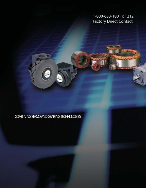
COMBINING SERVOAND GEARING TECHNOLOGIES<br />
1-800-633-1801 x 1212<br />
Factory Direct Contact
<strong>Frameless</strong> Motor & Gearmotors<br />
<strong>Frameless</strong><br />
142 <strong>Frameless</strong> <strong>Kit</strong> Motor<br />
Gearmotors<br />
156 GM Servo Gearmotors<br />
170 DX Servo Wheel<br />
180 Pancake Gearmotor<br />
RS:<br />
139
<strong>Frameless</strong> & Gearmotors: Application Solutions<br />
Stealth Gearmotors for Office Automation<br />
APPLICATION CHALLENGE<br />
A manufacturer of pressure form-folder/sealers, Bri-Lin, had a desire to develop a new product to replace their<br />
current table top model. The current model is typically used in the production of W2, wage, and wducation wrade<br />
report forms. The success of their new model was dependent on a number of design criteria required for an office<br />
setting inclusive of size, quiet operation with little to no maintenance. On the mechanical side, the requirements<br />
for speed control and constant torque was a must, but the critical objective of the new model would be a major<br />
productivity improvement over the 5,000 to 7,000 forms per hour offered by their present model.<br />
Design Change Criteria:<br />
Existing machine frame width must be maintained as these models are designed for desktop use utilizing<br />
8½ x 11 inch sheets. To maintain registration and speed control a DC servo is required. A brushless motor<br />
would be preferred for low maintenance and a "no dust" environment. This frame size does not accommodate<br />
an in-line or right-angle gearbox even if the cost could allow it.<br />
A gearmotors option would meet the speed/torque and size requirements, but the cable cost and connector<br />
size would be an issue.<br />
Cut the one-month delivery cycle of complete machine in half by utilizing a JIT component supplier with less<br />
than two-week lead times.<br />
APPLICATION CHALLENGE<br />
The customer manufactures an auger-filler machine that uses a fluted screw to volumetrically fill a<br />
container. The standard framed servomotor was mounted to the screw using a mechanical coupling device,<br />
gearbox and timing belt, but this proved unable to provide the performance required in a space-efficient<br />
package. When engineers were looking to improve their machine design, the issues they faced were:<br />
Large package size<br />
The motor, together with all the mechanical coupling and reduction devices, took up a lot of space on the<br />
machine.<br />
Overtorque and Runout<br />
The timing belts used in this application created a condition of overtorque and runout, which caused the<br />
auger screw to rub the side of the funnel.<br />
Reduced System Reliability<br />
These mechanical devices created reliability issues, causing down time and tolerance problems.<br />
APPLICATION CHALLENGE<br />
A major US manufacturer of vehicles was developing a new car powered by electric motors. Since the car<br />
had no gas-powered engine to drive the power-assist steering, alternate methods were required. Mechanical<br />
gearing was ruled out due to space requirements and standard electric motors would drain the batteries of the<br />
vehicle to quickly. The company had a problem and needed a unique, cost-effective solution. The opportunity<br />
was as follows:<br />
Reduced Package Size<br />
The unit needed to provide the torque with an effective weight-to-space ratio<br />
Rugged Design<br />
The motor had to operate in stringent “under the hood” conditions<br />
140
Parker Bayside SOLUTION<br />
GM90-D1A2F Brushless Servo Gearmotors with 10:1 ratio, with flying leads option.<br />
The Parker Bayside solution provided a cost-effective package of less than 8 inch overall length with a speed/<br />
torque capability that offered a 4 X productivity improvement, raising rates of production to 20,000 forms/hour. The<br />
incremental cost was nearly zero with reduced noise and need for routine maintenance. The one-piece gearmotors<br />
design with the rotor, sun gear and motor magnets attached reduces the need for multiple seals and bearings. The<br />
resulting package of the helical planetary brushless DC gearmotors was a small, quiet, powerful machine that runs<br />
clean and cool. The IP65 and stainless steel output shaft also lends itself to wet applications.<br />
Plans are now underway for the next generation; a 30,000 forms/hour unit on the drawing board utilizing<br />
Parker Bayside's next step up in gearmotors frame size, based on the success of the tested 20,000/hour Forms<br />
Folder/Sealer.<br />
This solution can be used in a variety of applications including:<br />
1. Packaging Industry 2. Printing/Graphics Industry 3. Medical/Pharmaceutical 4. Office Automation<br />
Parker Bayside SOLUTION<br />
(1) <strong>Frameless</strong> Brushless Motor<br />
The design problems were solved using a frameless kit motor integrated into the auger drive assembly. This<br />
allowed the manufacturer to build a single-shaft system eliminating the problems that existed before. Fewer<br />
parts were needed in the design, eliminating the couplings and bearings in the auger assembly. This increased<br />
reliability, allowing for higher speeds, accuracy and stiffness.<br />
Without couplings, timing belts and gearboxes, the customer was able to create a much more compact design.<br />
Due to increased reliability, down-time no longer becomes a critical issue for users.<br />
This solution can be used in packaging applications in the following industries:<br />
1. Consumer products 2.Food Processing 3. Medical/Pharmaceutical<br />
Parker Bayside SOLUTION<br />
(1) Custom-designed brushless steering pump motor.<br />
Parker Bayside engineering collaborated with the auto maker and its pump manufacturer and presented various<br />
options. The final solution was a custom-designed, high-efficiency motor directly driving the pump. The front<br />
mounting flange mated to the pump surface and formed the back end housing of the pump. A zer-porousity surface<br />
was therefore required for proper sealing. The housing was designed from an extrusion to minimize cost and<br />
maximize yield and was formed to plug into a unique low-profile drive/controller design. The stator was custom<br />
designed to operate at its highest efficiency point on a 48 volt DC bus.<br />
The solution was designed using (FEMA) "Failure effect mode analysis" methodology and put into manufacturing in<br />
record time.<br />
The efficiency of the motor assisted in providing maximum battery life for the vehicle.<br />
The motor was brushless and therefore required no maintenance.<br />
141<br />
The motor was designed to configurable for standard gas vehicles. 141
<strong>Frameless</strong><br />
Motor Series<br />
<strong>Frameless</strong> <strong>Kit</strong> <strong>Motors</strong>:<br />
Build your own high-performance motor<br />
Direct drive motion construction gives<br />
equipment designers the advantages of<br />
lower costs, increased reliability and<br />
improved performance
<strong>Frameless</strong> <strong>Kit</strong> Motor overview<br />
• The frameless motor allows for direct integration with a<br />
mechanical transmission device, eliminating parts that add size,<br />
complexity, response and settling time.<br />
• The design engineer is not constrained to the mounting interface<br />
and shaft dimensions of a typical framed motor.<br />
• The frameless motor offering comes in a wide range of sizes ranging<br />
from 32mm to 254mm in diameter providing a continuous torque from<br />
0.04 Nm to 58 Nm (see below).<br />
• Custom frame sizes are available for OEM applications.<br />
Traditional Coupled Motor<br />
Integrated <strong>Frameless</strong> <strong>Kit</strong> Motor<br />
Flexible Coupling<br />
Lead Screw<br />
Housing<br />
Ball Bearing<br />
(typical)<br />
Stator<br />
Rotor<br />
Motor<br />
<strong>Frameless</strong> <strong>Kit</strong> Motor Torque Range<br />
Stack Range Continuous Peak<br />
Frame Torque Torque<br />
Size (mm) (in) (Nm) (oz-in) (Nm) (oz-in)<br />
K032 6.35 to 50.8 0.25 to 2.00 0.044 to 0.22 6.3 to 31.1 0.095 to 0.654 13.5 to 93.4<br />
K044 6.35 to 50.8 0.25 to 2.00 0.119 to 0.607 17 to 86 0.357 to 1.820 50 to 258<br />
K064 6.35 to 50.8 0.25 to 2.00 0.31 to 2.16 44.3 to 308 0.93 to 6.47 133 to 924<br />
K089 6.35 to 50.8 0.25 to 2.00 1.307 to 4.291 186.7 to 613 3.92 to 12.87 560 to 1,839<br />
K375 6.35 to 50.8 0.25 to 2.00 1.715 to 4.935 245 to 705 5.14 to 14.82 734 to 2,117<br />
K127 12.7 to 50.8 0.50 to 2.00 3.94 to 11.75 563 to 1,678 11.83 to 35.24 1,690 to 5,034<br />
K500 12.7 to 50.8 0.50 to 2.00 3.05 to 9.44 435 to 1,349 9.14 to 28.32 1,306 to 4,046<br />
K178 12.7 to 50.8 0.50 to 2.00 10.12 to 30.7 1,445 to 4,386 16.18 to 49.12 2,312 to 7,017<br />
K700 12.7 to 50.8 0.50 to 2.00 5.05 to 17.52 722 to 2,503 8.09 to 28.03 1,155 to 4,004<br />
K254 12.7 to 50.8 0.50 to 2.00 18.78 to 58.35 2,683 to 8,336 30.04 to 93.37 4,292 to 13,338<br />
143
<strong>Frameless</strong><br />
Motor Series<br />
Build Your Own High-Performance Motor<br />
The frameless kit motors are ideal solutions for machine<br />
designs that require high performance in small spaces.<br />
The kit motors approach allows for direct integration with a<br />
mechanical-transmission device, eliminating parts that add size<br />
and complexity. The use of frameless kit motors results in a<br />
smaller, more reliable motor package.<br />
When to Use:<br />
A significant cost savings<br />
Reduced mechanical<br />
complexity<br />
Greater design flexibility<br />
High performance in a<br />
compact package<br />
Improved dynamic<br />
response and settling<br />
Applications:<br />
Automotive<br />
Machine tool<br />
Material handling<br />
Packaging<br />
Robotics<br />
Semiconductor<br />
Minimum motor size per<br />
application space<br />
Low cogging for<br />
smooth operation<br />
l<br />
9<br />
Low inertia for<br />
high acceleration<br />
8<br />
4<br />
7<br />
2<br />
6<br />
3<br />
5
What goes into our <strong>Frameless</strong> <strong>Kit</strong> <strong>Motors</strong>...<br />
Our direct drive brushless kit motors consist of three components:<br />
The stator and winding<br />
The rotor with high energy product neodymium magnets<br />
Hall sensor device for motor commutation<br />
What comes out of our <strong>Frameless</strong> <strong>Kit</strong> <strong>Motors</strong>...<br />
High Torque - from 0.06 Nm (0.5 in lb) to 9.7 Nm (85.6 in lb)<br />
High Speeds - up to 50,000 RPM<br />
Superior Performance - high stiffness and better response<br />
High Reliability - no mechanical transmission devices<br />
(couplings, flanges)<br />
Compact Design - minimizes product size<br />
Low Cogging - unique magnetic<br />
circuit design decreases cogging<br />
l<br />
Pre-installed Integral Commutation Board<br />
with Hall effects is prealigned for easy assembly. Motor and feedback<br />
as integrated unit.<br />
6<br />
High-Density Copper Winding<br />
for low thermal resistance and consistent performance across<br />
all motors.<br />
2<br />
Rare Earth Magnets<br />
provide high-flux in a small volume, high resistance to thermal<br />
demagnetizing.<br />
7<br />
Minimized End Turns<br />
to maximize performance. Formed to minimize motor size.<br />
3<br />
Rotor Assembly<br />
for easy mounting directly on the drive shaft with or without keyway.<br />
8<br />
Skewed Laminations<br />
with odd slot counts reduce cogging for precise rotary motion with drastically<br />
reduced torque ripple even at low speeds.<br />
4<br />
Machined Grooves<br />
to securely lock magnets to rotor and ensures optimized radial<br />
location.<br />
9<br />
Optimized Slot Fill<br />
for maximum torque-to-size ratio; hand inserted to obtain highest slot fill<br />
possible maximizing ampere-turns.<br />
5<br />
Class H Insulation<br />
for high-temperature operation (up to 155ºC) meeting UL approved<br />
requirements.<br />
145
<strong>Frameless</strong><br />
Motor Series<br />
KO32 to KO254 <strong>Motors</strong><br />
Performance Specifications (six step/trapezoidal commutation)<br />
Stack Continuous Peak Motor Core Rotor Electrical Thermal Weight<br />
Frame Length Torque (1) Torque Constant Loss Inertia Time Resistance<br />
Size<br />
Constant<br />
T c T p K m P c J m T c Wm<br />
(mm) (in) (Nm) (oz in) (Nm) (oz in) (Nm / W) (oz in / W) W @1kRPM (gm cm sec 2 ) (oz in sec 2 ) (msec) ( o C / W) (kg) (oz)<br />
K032025 6.35 0.25 0.044 6.3 0.095 13.5 0.009 1.25 0.03 0.0016 0.000022 0.21 3.44 0.042 1.5<br />
K032050 12.7 0.5 0.08 11.4 0.188 27 0.016 2 0.06 0.0032 0.000045 0.35 3.44 0.068 2.4<br />
K032075 19.05 0.75 0.11 15.7 0.281 40 0.022 3 0.09 0.0048 0.000067 0.44 3.44 0.096 3.4<br />
K032100 25.4 1 0.136 19.4 0.375 54 0.027 4 0.12 0.0064 0.000089 0.5 3.44 0.122 4.3<br />
K032150 38.1 1.5 0.181 25.8 0.544 77.7 0.036 5.15 0.18 0.0096 0.000134 0.6 3.44 0.173 6.1<br />
K032200 50.8 2 0.22 31.1 0.654 93.4 0.044 6.25 0.24 0.013 0.000178 0.66 3.44 0.26 9.2<br />
K032300 76.2 3 0.33 46.5 0.99 139.5 0.054 7.56 0.36 0.0192 0.000268 0.7 3.44 0.36 12.8<br />
K044025 6.35 0.25 0.119 17 0.357 50 0.02 3 0.11 0.0072 0.0001 0.39 2.36 0.085 3<br />
K044050 12.7 0.5 0.214 30.6 0.642 90 0.035 5 0.24 0.014 0.0002 0.62 2.36 0.133 5<br />
K044075 19.05 0.75 0.297 42.4 0.891 127 0.049 7 0.37 0.022 0.0003 0.76 2.36 0.200 7<br />
K044100 25.4 1 0.364 52 1.092 156 0.06 9 0.49 0.03 0.00041 0.89 2.36 0.224 8<br />
K044150 38.1 1.5 0.501 71 1.510 213 0.08 11.4 0.74 0.044 0.00061 1.05 2.36 0.311 11<br />
K044200 50.8 2 0.607 86 1.820 258 0.097 13.8 1.11 0.06 0.00082 1.12 2.36 0.399 14.1<br />
K044300 76.2 3 0.96 136.0 2.88 408 0.13 18.3 1.48 0.088 0.00122 1.3 2.36 0.549 19.4<br />
K064025 6.35 0.25 0.31 44.3 0.93 133 0.048 6.88 0.37 0.046 0.00064 0.59 1.68 0.142 5<br />
K064050 12.7 0.5 0.62 89 1.87 267 0.087 12.48 0.78 0.092 0.00128 0.98 1.68 0.286 10.1<br />
K064075 19.05 0.75 0.85 121.7 2.56 365 0.122 17.44 1.19 0.138 0.00192 1.26 1.68 0.427 15.1<br />
K064100 25.4 1 1.08 154 3.23 462 0.15 21.44 1.6 0.184 0.00256 1.47 1.68 0.572 20.2<br />
K064150 38.1 1.5 1.46 209 4.39 627 0.204 29.12 2.37 0.276 0.00384 1.77 1.68 0.846 30.2<br />
K064200 50.8 2 2.16 308 6.47 924 0.244 34.88 3.23 0.369 0.00512 1.97 1.68 1.129 40.3<br />
K064300 76.2 3 2.91 410 8.73 1,230 0.33 46.6 4.74 0.552 0.00768 2.6 1.68 1.701 60.5<br />
K089050 12.7 0.5 1.307 186.7 3.92 560 0.164 23.36 2.14 0.38 0.00528 1.26 1.02 0.498 17.6<br />
K089075 19.05 0.75 1.96 280 5.88 840 0.235 33.6 3.35 0.576 0.008 1.64 1.02 0.747 26.4<br />
K089100 25.4 1 2.618 374 7.84 1,120 0.283 40.64 4.42 0.792 0.0011 1.92 1.02 0.996 35.2<br />
K089150 38.1 1.5 3.92 560 11.76 1,680 0.381 54.4 6.7 1.15 0.016 2.33 1.02 1.494 52.8<br />
K089200 50.8 2 4.291 613 12.87 1,839 0.466 66.56 8.95 1.51 0.021 2.6 1.02 1.992 70.4<br />
K089300 76.2 3 7.13 1,004 21.4 3,012 0.631 88.9 13.4 2.30 0.032 2.9 1.02 3.00 105.6<br />
(1) = Housed in a motor frame. Pole Count<br />
Typically an aluminum cylinder with 6.35mm (0.250in) thick walls, K032 is 4<br />
K032, K044 and K064 mounted to a 152mm x 152mm x 12.5 mm (6in x 6in x 0.5in) aluminum plate K044 is 6<br />
K089 mounted to a 203mm x 203mm x 12.5mm (8in x 8in x 0.5in) aluminum plate K064 is 8<br />
K089 is 12
Stack Continuous Peak Motor Core Rotor Electrical Thermal Weight<br />
Frame Length Torque (1) Torque Constant Loss Inertia Time Resistance<br />
Size<br />
Constant<br />
T c T p K m P c J m T c Wm<br />
(mm) (in) (Nm) (oz in) (Nm) (oz in) (Nm / W) (oz in / W) W@1kRPM (gm cm sec 2 ) (oz in sec 2 ) (msec) ( o C / W) (kg) (oz)<br />
K375050 12.7 0.5 1.715 245 5.14 734 0.153 21.8 1.2 0.324 0.0045 1.45 1.02 0.611 21.6<br />
K375075 19.05 0.75 2.401 343 7.19 1,027 0.213 30.4 1.8 0.497 0.0069 1.9 1.02 0.917 32.4<br />
K375100 25.4 1 3.003 429 9 1,286 0.267 38.1 2.4 0.655 0.0091 2.24 1.02 1.095 38.7<br />
K375150 38.1 1.5 4.025 575 12.6 1,723 0.357 51 3.6 1.01 0.014 2.68 1.02 1.554 54.9<br />
K375200 50.8 2 4.935 705 14.82 2,117 0.438 62.6 4.8 1.30 0.018 3.03 1.02 2.02 71.1<br />
K375300 76.2 3 6.69 942 20.1 2,826 0.592 83.4 7.2 2.02 0.028 3.5 1.02 2.94 103.5<br />
K127050 12.7 0.5 3.94 563 11.83 1,690 0.29 41.4 4.7 1.15 0.016 2.38 0.7 1.087 38.4<br />
K127100 25.4 1 6.98 997 21.04 3,006 0.513 73.3 9.6 2.38 0.033 3.7 0.7 1.766 62.4<br />
K127150 38.1 1.5 9.56 1,365 28.66 4,094 0.702 100.3 14.5 3.53 0.049 4.6 0.7 2.355 83.2<br />
K127200 50.8 2 11.75 1,678 35.24 5,034 0.864 123.4 19.4 4.75 0.066 5.23 0.7 2.99 105.6<br />
K127300 76.2 3 16.1 2,263 48.3 6,789 1.18 166.1 29.0 7.06 0.098 6.1 0.7 3.65 147.2<br />
K500050 12.7 0.5 3.05 435 9.14 1,306 0.224 32 1.6 1.15 0.016 2.6 0.7 1.087 38.4<br />
K500100 25.4 1 5.49 784 16.46 2,352 0.403 57.6 3 2.30 0.032 4.5 0.7 1.766 62.4<br />
K500150 38.1 1.5 7.92 1,131 23.76 3,394 0.582 83.2 4.8 3.46 0.048 6 0.7 2.355 83.2<br />
K500200 50.8 2 9.44 1,349 28.32 4,046 0.694 99.2 6.4 4.61 0.064 6.4 0.7 2.988 105.6<br />
K500300 76.2 3 15.4 2,170 46.2 6,510 1.13 159.3 8.6 6.92 0.096 8.0 0.7 4.18 147.2<br />
K178050 12.7 0.5 10.12 1,445 16.18 2,312 0.627 89.6 9.1 4.75 0.066 4.16 0.5 2.4 84.8<br />
K178100 25.4 1 18.06 2,580 28.89 4,127 1.12 160 18.7 9.36 0.13 6.54 0.5 3.71 131.2<br />
K178150 38.1 1.5 24.75 3,535 39.59 5,655 1.534 219 14.4 14.4 0.2 8.15 0.5 4.98 176<br />
K178200 50.8 2 30.7 4,386 49.12 7,017 1.904 272 18.7 18.7 0.26 9.31 0.5 6.34 224<br />
K178300 76.2 3 43.1 6,078 69.0 9,724 2.68 377 28.8 28.8 0.4 12.2 0.5 8.90 313.6<br />
K700050 12.7 0.5 5.05 722 8.09 1,155 0.314 44.8 7.70 7.7 0.107 2.9 0.4 2.4 84.8<br />
K700100 25.4 1 9.57 1,367 15.32 2,188 0.594 84.8 15.4 15.4 0.214 5 0.4 3.71 131.2<br />
K700150 38.1 1.5 13.55 1,935 21.67 3,096 0.84 120 23.2 23.2 0.322 6.8 0.4 4.98 176<br />
K700200 50.8 2 17.52 2,503 28.03 4,004 1.086 155.2 30.9 31 0.429 8.5 0.4 6.34 224<br />
K700300 76.2 3 27.5 3,876 44.0 6,200 1.53 215 46.4 46.4 0.644 10.7 0.4 8.91 313.6<br />
K254050 12.7 0.5 18.78 2,683 30.04 4,292 1.043 149 17.9 17.9 0.248 6.05 0.4 4.48 158.4<br />
K254100 25.4 1 33.92 4,846 54.27 7,753 1.883 269 35.5 35.5 0.493 9.63 0.4 6.79 240<br />
K254150 38.1 1.5 46.84 6,692 74.95 10,707 2.597 371 53.1 53.1 0.738 12.5 0.4 9.056 320<br />
K254200 50.8 2 58.35 8,336 93.37 13,338 3.234 462 71.0 71 0.986 14.7 0.4 11.32 400<br />
K254300 76.2 3 80.9 11,400 129.4 18,240 4.49 632 106.2 106 1.478 18.0 0.4 15.9 560<br />
(1) = Housed in a motor frame. Typically an aluminum cylinder with 6.35mm (0.250in) thick walls, Pole Count:<br />
K375, K127 and K500 mounted to a 305mm x 305mm x 12.5mm (12in x 12in x 0.5in) aluminum plate. K127 & K375 are 12<br />
K178, K700 and K254 mounted to a 406mm x 406mm x 12.5mm (16in x 16in x 0.5in) aluminum plate. K700 & K500 are 8<br />
K178 & K254 are 18<br />
147
<strong>Frameless</strong><br />
Motor Series<br />
KO32 to KO254 <strong>Motors</strong><br />
Dimensions<br />
Stack<br />
Length<br />
+1.3 (0.05")<br />
-0<br />
See table on page 176<br />
Lead Length: 450mm/18in<br />
A<br />
B C<br />
MAX MIN<br />
D<br />
E<br />
F<br />
MAX<br />
MAX<br />
Stator Outline<br />
A B C D E F<br />
O.D. End Turns End Turns I.D. End Turns Commutation<br />
Frame O.D. I.D. Length Length<br />
Size (mm) (in) (mm) (in) (mm) (in) (mm) (in) (mm) (in) (mm) (in)<br />
K032<br />
K044<br />
K064<br />
K089<br />
K375<br />
K127<br />
K500<br />
K178<br />
K700<br />
K254<br />
31.78 1.251 27.94 1.1 16.51 0.65 15.06 0.593 6.4 0.25 14.5 0.57<br />
31.75 1.25 14.8 0.583<br />
44.48 1.751 40.64 1.6 26.16 1.03 22.35 0.88 7.9 0.31 16.5 0.65<br />
44.42 1.749 22.09 0.87<br />
63.52 2.501 60.7 2.39 38.1 1.5 35.18 1.385 9.65 0.38 17.5 0.69<br />
63.47 2.499 34.92 1.375<br />
88.92 3.501 85.8 3.38 54.6 2.15 53.47 2.105 9.91 0.39 17.5 0.69<br />
88.87 3.499 53.21 2.095<br />
95.28 3.751 88.9 3.5 53.32 2.06 50.93 2.005 12.7 0.5 19.5 0.77<br />
95.22 3.749 50.67 1.995<br />
127.02 5.001 122.17 4.81 74.17 2.92 72.49 2.854 12.7 0.5 19.5 0.77<br />
126.97 4.999 72.23 2.844<br />
127.05 5.002 115.32 4.54 70.6 2.78 68.2 2.685 20.5 0.81 30.5 1.2<br />
126.95 4.998 67.94 2.675<br />
177.88 7.003 172.72 6.8 111.51 4.39 110.64 4.355 20.3 0.8 *<br />
177.72 6.997 110.38 4.345<br />
177.88 7.003 158.24 6.23 117.6 4.63 115.19 4.535 18.8 0.74 *<br />
177.72 6.997 114.93 4.525<br />
254.07 10.003 253.26 9.971 165.1 6.5 157.61 6.205 19.6 0.77 *<br />
253.92 9.997 157.35 6.195<br />
*integral commutation not available
K<br />
Stator<br />
G<br />
H<br />
Rotor<br />
Commutation<br />
PCB<br />
with Hall<br />
devices<br />
Stack<br />
Length<br />
Rotor Outline<br />
I<br />
Figure 1.3<br />
<strong>Kit</strong> Main Components<br />
G H I K<br />
Rotor O.D. Rotor I.D. Commutation Magnet Rotor Length<br />
Frame<br />
Length<br />
Size (mm) (in) (mm) (in) (mm) (in)<br />
K032<br />
K044<br />
K064<br />
K089<br />
K375<br />
K127<br />
K500<br />
K178<br />
K700<br />
K254<br />
13.94 0.549 7.62 0.3 13.21 0.52 without Commutation:<br />
13.89 0.547 7.59 0.299 K = Stack Length + 0.76mm (0.030in)<br />
21.23 0.836 13.97 0.55 14.73 0.58<br />
21.18 0.834 13.94 0.549 with Commutation:<br />
34.04 1.34 23.52 0.926 16.51 0.65 K = Stack Length + I + 0.76mm (0.030in)<br />
33.98 1.338 23.49 0.925<br />
51.84 2.041 40.64 1.6 16.71 0.66<br />
51.79 2.039 40.61 1.599<br />
49.28 1.94 38.1 1.5 19.56 0.77<br />
49.15 1.935 38.07 1.499<br />
71.15 2.801 58.42 2.3 19.56 0.77<br />
71.09 2.799 58.39 2.299<br />
66.54 2.62 50.83 2.001 28.52 1.12<br />
66.5 2.618 50.8 2<br />
109.2 4.292 95.76 3.77 *<br />
108.9 4.29 95.73 3.769<br />
113.54 4.47 95.25 3.75 *<br />
113.49 4.468 95 3.74<br />
156.16 6.148 140.46 5.53 *<br />
156.11 6.146 140.44 5.529<br />
*integral commutation not available<br />
149
<strong>Frameless</strong><br />
Motor Series<br />
Winding Selection<br />
The selection of a particular frame size and winding for an application is<br />
dependent on:<br />
Volume (diameter and length) requirement<br />
Power (torque and speed) requirement<br />
Voltage and current available or required<br />
The first two items are dependent on the load and performance specifications<br />
of the application. They result in the selection of a particular frame size (032<br />
through 254) and stack length.<br />
The winding to be used will then be determined by voltage and current<br />
available or required.<br />
Voltage: The bus voltage and maximum speed will<br />
approximately determine the required voltage<br />
constant (K E ).<br />
Current: The maximum load and acceleration will determine<br />
the amount of current required, determined by the<br />
torque constant (K T ) associated with the selected<br />
voltage constant.<br />
Example: Assume a requirement of 1,000 RPM at 50 oz in<br />
If a motor with a particular winding having<br />
K E = 18.24 V/1,000 RPM and K T = 24.62 oz in/amp<br />
is chosen, it will now require a voltage (BEMF) of<br />
18 volts and current of 2 amp.<br />
NOTE:<br />
K E and K T are directly proportional to each other.<br />
Increasing K E will also increase K T ; Decreasing K E<br />
will also decrease K T .<br />
The result is that as the voltage requirement changes,<br />
the current requirement changes inversely.<br />
Parker Bayside has a range of 27 windings available for each frame size and<br />
stack length, providing for virtually any practical combination of voltage and<br />
current required for your application.<br />
The following pages show just a small representative sample of speed/torque<br />
curves for each of the 10 frame sizes available.<br />
For the 044, 064, 089 and 127 frame sizes, the speed/torque curves are for<br />
stators that are used in the standard BM / GM motor products.<br />
They make a good starting point for determining your specific application<br />
requirements and working with Parker Bayside application engineers to choose<br />
the proper motor size and power.<br />
The following table lists the range of K E and K T available for each of the<br />
10 frame sizes.<br />
Detailed information for all these windings can be found on the web site:<br />
www.baysidemotion.com or www.parkermotion.com<br />
Frame Stack Range K E Range K T Range<br />
Size (mm) (in) (V/1,000 RPM) (V/rad/sec) (Nm/amp) (oz in/amp)<br />
K032 6.35 to 50.8 0.25 to 2.00 0.14 to 65.52 0.0013 to 0.625 0.0013 to 0.625 0.18 to 88.45<br />
K044 6.35 to 50.8 0.25 to 2.00 0.28 to 126.3 0.0027 to 1.2 0.0027 to 1.2 0.38 to 170.6<br />
K064 6.35 to 50.8 0.25 to 2.00 0.66 to 291.8 0.0063 to 2.78 0.0063 to 2.78 0.89 to 394<br />
K089 6.35 to 50.8 0.25 to 2.00 1.35 to 605 0.013 to 5.77 0.013 to 5.77 1.83 to 817<br />
K375 6.35 to 50.8 0.25 to 2.00 1.27 to 566 0.012 to 5.40 0.012 to 5.40 1.71 to 765<br />
K127 12.7 to 50.8 0.50 to 2.00 3.73 to 827 0.036 to 7.88 0.036 to 7.88 5.04 to 1116<br />
K500 12.7 to 50.8 0.50 to 2.00 3.38 to 714 0.032 to 6.81 0.032 to 6.81 4.56 to 964<br />
K178 12.7 to 50.8 0.50 to 2.00 8.26 to 1716 0.079 to 16.4 0.079 to 16.4 11.18 to 2,323<br />
K700 12.7 to 50.8 0.50 to 2.00 4.14 to 872 0.039 to 8.31 0.039 to 8.31 5.59 to 1,177<br />
K254 12.7 to 50.8 0.50 to 2.00 11.44 to 2,537 0.109 to 24.2 0.109 to 24.2 15.5 to 3,425<br />
NOTE: Longer stacks and special windings are available. Call 1-800-305-4555
Speed/Torque Curves<br />
K032150-7Y<br />
K T = 0.051 Nm / amp (7.19 oz-in / amp) R T-T = 2.05 Ω I cont = 3.6 amp<br />
K E = 0.051 v / rad / sec (5.32 V / kRPM) L T-T = 1.16 mH I peak = 10.8 amp<br />
10<br />
E BUS = 48 Vdc<br />
K044150-FY<br />
K T = 0.28 Nm / amp (39.6 oz-in / amp) R T-T = 11.8 Ω I cont = 2 amp<br />
K E = 0.28 v / rad / sec (29.3 V / kRPM) L T-T = 12.5 mH I peak = 6 amp<br />
E BUS = 160 Vdc<br />
8<br />
6<br />
6<br />
5<br />
Speed (kRPM)<br />
4<br />
2<br />
continuous<br />
intermittent<br />
Speed (kRPM)<br />
4<br />
3<br />
2<br />
1<br />
continuous<br />
intermittent<br />
0<br />
0 0.1 0.2 0.3 0.4 0.5<br />
0.6 (Nm)<br />
0<br />
0 0.25 0.50 0.75 1.0 1.25 1.5 1.75<br />
(Nm)<br />
0<br />
10 20 30 40 50 60 70<br />
80<br />
(oz in)<br />
0 50 100 150 200 250<br />
(oz in)<br />
Torque<br />
Torque<br />
K044300-8Y<br />
K T = 0.28 Nm / amp (39.6 oz-in / amp) R T-T = 4.8 Ω I cont = 3 amp<br />
K E = 0.28 v / rad / sec (29.3 V / kRPM) L T-T = 6.2 mH I peak = 9 amp<br />
6<br />
5<br />
4<br />
E BUS = 160 Vdc<br />
K064150-8Y<br />
K T = 0.33 Nm / amp (46.1 oz-in / amp) R T-T = 2.5 Ω I cont = 6 amp<br />
K E = 0.33 v / rad / sec (34.1 V / kRPM) L T-T = 4.5 mH I peak = 18 amp<br />
E BUS = 160 Vdc<br />
6<br />
5<br />
4<br />
Speed (kRPM)<br />
3<br />
2<br />
Speed (kRPM)<br />
3<br />
2<br />
1<br />
continuous<br />
intermittent<br />
1<br />
continuous<br />
intermittent<br />
0<br />
0<br />
0.25 0.50 0.75 1.0 1.25 1.5 1.75 2.0 2.25 2.5 2.75 (Nm)<br />
0<br />
0<br />
1 2 3 4 5<br />
6 (Nm)<br />
0 50 100 150 200 250 300 350 400 (oz in)<br />
0 100 200<br />
300<br />
400 500 600 700 800<br />
(oz in)<br />
Torque<br />
Torque<br />
K064300-6Y<br />
K T = 0.42 Nm / amp (59.9 oz-in / amp) R T-T = 1.6 Ω I cont = 7 amp<br />
K E = 0.42 v / rad / sec (44.3 V / kRPM) L T-T = 3.8 mH I peak = 21 amp<br />
E BUS = 160 Vdc<br />
K375150-6Y<br />
K T = 0.41 Nm / amp (57.92 oz-in / amp) R T-T = 1.21 Ω I cont = 10 amp<br />
K E = 0.41 v / rad / sec (47.82 V / kRPM) L T-T = 3.45 mH I peak = 30 amp<br />
E BUS = 160 Vdc<br />
6<br />
6<br />
5<br />
5<br />
Speed (kRPM)<br />
4<br />
3<br />
2<br />
Speed (kRPM)<br />
4<br />
3<br />
2<br />
1<br />
continuous<br />
intermittent<br />
1<br />
continuous<br />
intermittent<br />
0<br />
0<br />
1 2 3 4 5 6 7 8 9 10 (Nm)<br />
0<br />
0<br />
2 4 6 8 10 12 14 (Nm)<br />
0 200 400 600 800 1000 1200 1400 (oz in)<br />
Torque<br />
0 200 400 600 800 1.0k 1.2k 1.4k 1.6k 1.8k 2.0k (oz in)<br />
Torque<br />
151
<strong>Frameless</strong><br />
Motor Series<br />
Speed/Torque Curves<br />
K089150-6Y<br />
K T = 0.43 Nm / amp (61.6 oz-in / amp) R T-T = 1.2 Ω I cont = 11 amp<br />
K E = 0.43 v / rad / sec (45.6 V / kRPM) L T-T = 2.9 mH I peak = 33 amp<br />
E BUS = 160 Vdc<br />
6<br />
K089300-4Y<br />
K T = 0.54 Nm / amp (75.8 oz-in / amp) R T-T = 0.73 Ω I cont = 15 amp<br />
K E = 0.54 v / rad / sec (56.1 V / kRPM) L T-T = 2.2 mH I peak = 45 amp<br />
E BUS = 160 Vdc<br />
6<br />
5<br />
4<br />
5<br />
4<br />
Speed (kRPM)<br />
3<br />
2<br />
1<br />
continuous<br />
intermittent<br />
Speed (kRPM)<br />
3<br />
2<br />
1<br />
continuous<br />
intermittent<br />
0<br />
0<br />
2 4 6 8 10 12 14 (Nm)<br />
0<br />
0<br />
4 8 12 16 20 24 (Nm)<br />
0 200 400 600 800 1.0k 1.2k 1.4k 1.6k 1.8k 2.0k (oz in)<br />
0 400 800 1.2k 1.6k 2.0k 2.4k 2.8k 3.2k (oz in)<br />
Torque<br />
Torque<br />
K127250-4Y<br />
K T = 0.61 Nm / amp (86.9 oz-in / amp) R T-T = 0.35 Ω I cont = 20 amp<br />
K E = 0.61 v / rad / sec (64.2 V / kRPM) L T-T = 2.1 mH I peak = 60 amp<br />
5<br />
E BUS = 300 Vdc<br />
K127500-3Y<br />
K T = 0.92 Nm / amp (130.4 oz-in / amp) R T-T = 0.34 Ω I cont = 24 amp<br />
K E = 0.92 v / rad / sec (96.4 V / kRPM) L T-T = 2.3 mH I peak = 72 amp<br />
5<br />
E BUS = 300 Vdc<br />
4<br />
<br />
4<br />
<br />
3<br />
3<br />
Speed (kRPM)<br />
2<br />
1<br />
continuous<br />
intermittent<br />
Speed (kRPM)<br />
2<br />
1<br />
continuous<br />
intermittent<br />
0<br />
10 20 30 40 50 60 70<br />
(Nm)<br />
0<br />
0<br />
10 20 30 40 50 60 70<br />
(Nm)<br />
0<br />
1k 2k 3k 4k 5k 6k 7k 8k 9k 10k (oz in)<br />
Torque<br />
0 1k 2k 3k 4k 5k 6k 7k 8k 9k 10k (oz in)<br />
Torque<br />
K500150-5Y<br />
K T = 0.45 Nm / amp (63.78 oz-in / amp) R T-T = 0.49 Ω I cont = 18 amp<br />
K E = 0.45 v / rad / sec (47.19 V / kRPM) L T-T = 2.72 mH I peak = 53 amp<br />
E BUS = 300 Vdc<br />
8<br />
7<br />
6<br />
K178150-5Y<br />
K T = 0.93 Nm / amp (130.5 oz-in / amp) R T-T = 0.37 Ω I cont = 27 amp<br />
K E = 0.93 v / rad / sec (96.2 V / kRPM) L T-T = 2.95 mH I peak = 43 amp<br />
E BUS = 300 Vdc<br />
5<br />
4<br />
Speed (kRPM)<br />
5<br />
4<br />
3<br />
Speed (kRPM)<br />
3<br />
2<br />
2<br />
1<br />
continuous<br />
intermittent<br />
1<br />
continuous<br />
intermittent<br />
0<br />
0 4 8 12 16 20 24 28<br />
(Nm)<br />
0<br />
0<br />
6 12 18 24 30 36 42 (Nm)<br />
0 500 1.0k 1.5k 2.0k 2.5k 3.0k 3.5k 4.0k (oz in)<br />
Torque<br />
0 500 1.0k 1.5k 2.0k 2.5k 3.0k 3.5k 4.0k 4.5k 5.0k 5.5k (oz in)<br />
Torque
How to Order<br />
K700150-7Y<br />
K T = 0.78 Nm / amp (110.35 oz-in / amp) R T-T = 0.84 Ω I cont = 18 amp<br />
K E = 0.78 v / rad / sec (81.71 V / kRPM) L T-T = 5.79 mH I peak = 28 amp<br />
E BUS = 300 Vdc<br />
K254150-5Y<br />
K T = 1.42 Nm / amp (199.7 oz-in / amp) R T-T = 0.78 Ω I cont = 34 amp<br />
K E = 1.42 v / rad / sec (147.6 V / kRPM) L T-T = 3.6 mH I peak = 54 amp<br />
E BUS = 300 Vdc<br />
5<br />
5<br />
4<br />
4<br />
3<br />
3<br />
Speed (kRPM)<br />
2<br />
1<br />
continuous<br />
intermittent<br />
Speed (kRPM)<br />
2<br />
1<br />
continuous<br />
intermittent<br />
0<br />
0<br />
6 12 18 24 30 36 42 (Nm)<br />
0<br />
0<br />
12 24 36 48 60 72 84 (Nm)<br />
0 500 10k 15k 20k 25k 30k 35k 40k 45k 50k 55k ( i )<br />
Torque<br />
0 1k 2k 3k 4k 5k 6k 7k 8k 9k 10k 11k 12k (oz in)<br />
Torque<br />
MOUNTING FRAMELESS MOTOR INTO ASSEMBLY<br />
This section outlines a number of methods that can be used to mount the stator<br />
and rotor assemblies in the product.<br />
Which method to be used will largely depend on the product design, performance<br />
requirements (torque, velocity, temperature, etc.) and the manufacturing<br />
capabilities of the user.<br />
Dimensioned drawings for all the kits are shown in the catalog pages.<br />
STATOR<br />
The stator will be typically be mounted into a cylindrically shaped hole in the<br />
product (see Figure 9). It is recommended that a banking step be incorporated at<br />
the bottom of the hole to assure accurate and repeatable location of the stator.<br />
Alternately, a non-ferrous "plug" could be used to provide a banking surface,<br />
which can be removed once the stator is fixed in place.<br />
Figure 9 shows two methods for holding the stator in position; either with<br />
adhesive for a permanent assembly or with set screws for a removable<br />
assembly.<br />
In designing the housing, be sure to provide a means for the stator lead wires<br />
(three) and the commutation Hall sensor PCB wires (five) to extend outside of the<br />
housing without interfering with the rotor / shaft assembly.<br />
For volume production, a jig should be fabricated that will assure that the stator<br />
is located in the same position for each assembly. The yellow dot on the stator<br />
provides an index point for accomplishing this. This will eliminate the need to<br />
perform mechanical commutation alignment at final assembly.<br />
Rotor<br />
Except for the smaller motors (K032 and K044), the ID of the rotor will usually be<br />
larger than the shaft diameter.<br />
An adapter sleeve will be required to allow mounting of the rotor to the shaft (see<br />
Figure 9).<br />
The rotor / sleeve assembly must be positioned on the shaft such that the<br />
magnets are located in line with the stator assembly laminations. If the version<br />
in which the commutation PCB assembly is bonded to the end turns is being<br />
used, the commutation magnets must be located in proper proximity to the Hall<br />
sensors on the PCB. Figure 9 shows two methods for holding the rotor / sleeve<br />
on the shaft, either with adhesive or by using a spring pin and retaining ring.<br />
When using the adhesive method, a shoulder should be provided on the shaft to<br />
properly locate the rotor/sleeve assembly.<br />
When using the spring pin/retaining ring method, a slot must be provided in the<br />
sleeve that will engage the spring pin in the shaft, thus properly locating the<br />
rotor / sleeve assembly. During assembly, be sure that the pin and slot are fully<br />
engaged.<br />
Note: The following adhesives are recommended for rotor and stator assembly<br />
(see Figure 9)<br />
Assembly<br />
Loctite #325<br />
Activator $7074<br />
Loctite #609<br />
Stator Assembly:<br />
Assemble stator in housing or sleeve (aluminum recommended) with the<br />
following locational clearances:<br />
• Diameter to 127mm (5in) 0.025mm (0.001in) to 0.127mm (0.005in)<br />
diametrical clearance.<br />
• Diameter over 127mm (5in) 0.05mm (0.002in) to 0.254mm (0.010in)<br />
diametrical clearance.<br />
Do not force stator in position. This may damage or deform stator.<br />
Permanent Assembly:<br />
Secure stator with adhesive, Loctite #325 with activator #7074 or equivalent<br />
Removable Assembly:<br />
Secure with cup point screws or setscrews thru housing into stator steel<br />
laminations only. Use a minimum of three (3) screws equally spaced about stator<br />
O.D. Tighten evenly. Do not over torque screws. This may damage or deform<br />
stator.<br />
153
<strong>Frameless</strong><br />
Motor Series<br />
Rotor<br />
Retaining Ring<br />
Slot<br />
Adapter<br />
Sleeve<br />
Adapter Sleeve<br />
Commutation Wires (3)<br />
Commutation PCB<br />
Assy<br />
Set<br />
Screws<br />
Spring Pin<br />
Groove<br />
Shaft<br />
Stator Wires (3)<br />
Stator<br />
Shaft<br />
Shoulder<br />
Housing<br />
Spring Pin / Retaining Ring Method<br />
Shoulder / Adhesive Method<br />
1) Optional Retaining Ring<br />
or Shoulder<br />
Optional Integral<br />
Commuation<br />
1) 2) Rotor / Shaft Sleeve<br />
Stator End Turns<br />
Optional Cup Point Set Screws<br />
min 3 eq. sp.<br />
Motor Housing<br />
Stator (Laminations)<br />
2) Optional Banking Step.<br />
0.635mm (0.025in) w max<br />
Rotoar Assembly Magnets and Stator<br />
Lamination to be in line<br />
Drive Shaft<br />
or Bearing Assembly<br />
1) Anti-rotation Spring Pin or<br />
Keyway<br />
Figure 9
Rotor Assembly:<br />
Assemble rotor to shaft with a locational clearance fit of 0.013mm (0.0005in) to<br />
0.038mm (0.0015in) diametrical clearance.<br />
Shoulder / Adhesive Method:<br />
Fabricate shaft with shoulder. Secure rotor assembly and sleeve with adhesive.<br />
Loctite#609 or equivalent.<br />
Spring Pin / Retaining Ring Method:<br />
Fabricate a sleeve (steel or aluminum) with anti rotation spring pin groove.<br />
Fabricate shaft to accept retaining ring and spring pin. Permanently bond to<br />
rotor assembly.<br />
Final Assembly:<br />
Rotor magnets to be in line with stator laminations and concentric to stator<br />
lamination I.D. within 0.127mm (0.005in) MAX.<br />
Caution:<br />
Rotor assembly magnets are powerful and fragile!<br />
Do not place near magnetically sensitive material<br />
Do not place near other ferromagnetic materials such as iron, steel and nickel<br />
alloys. Strong uncontrolled attraction may damage magnets on contact.<br />
When assembling the rotor into the stator, high radial forces will be experienced,<br />
which can cause the magnets to "crash" into the stator and be damaged and / or<br />
cause bodily injury!<br />
The following precautions should be taken:<br />
Wrap the rotor with a thin (0.005in thick) Mylar sleeve which will fill the air<br />
gap between the rotor and stator during assembly and can be easily removed<br />
when assembly is complete.<br />
Support the rotor and stator assemblies in a fixturing arrangement which will<br />
prevent radial motion while the two assemblies are being mated.<br />
Example:<br />
1. Hold the rotor / shaft / product assembly in a machine tool vise on the base of<br />
an arbor press.<br />
2. Fasten the stator assembly to the vertical moving member of the arbor press,<br />
away from the stator.<br />
3. Slowly lower the stator assembly around the rotor / shaft / product assembly.<br />
4. Tighten all fasteners to complete assembly.<br />
5. Remove Mylar shim and check for rotational clearance.<br />
Improper assembly of rotor into stator can cause serious injury and or damage to<br />
equipment.<br />
How to Order<br />
Order<br />
Numbering<br />
Example:<br />
K 0 4 4 1 0 0 – E Y 2 XXX<br />
MODEL<br />
032<br />
044<br />
064<br />
089<br />
375<br />
127<br />
500<br />
178<br />
700<br />
254<br />
STACK LENGTH<br />
025 (0.25”)<br />
050 (0.50”)<br />
075 (0.75”)<br />
100 (1.00”)<br />
150 (1.50”)<br />
200 (2.00”)<br />
WINDING (1)<br />
1<br />
2<br />
3<br />
4<br />
5<br />
6<br />
7<br />
8<br />
9<br />
E<br />
F<br />
G<br />
H<br />
J<br />
K<br />
L<br />
CONNECTION (2)<br />
Y=Wye<br />
D=Delta<br />
COMMUTATION<br />
1 = Without<br />
2 = With Integral<br />
(1) Consult Parker Bayside (1-800-305-4555 or<br />
www.baysidemotion.com or www.parkermotion.com)<br />
for specific winding designations.<br />
(2) Consult factory for special options<br />
Parker Bayside <strong>Kit</strong> <strong>Motors</strong> are supported by a worldwide network of offices and local distributors.<br />
Call 1-800-305-4555 for application engineering assistance or for the name of your local distributor.<br />
Information can also be obtained at www.baysidemotion.com or www.parkermotion.com.<br />
Specifications are subject to change without notice.<br />
155
Stealth GM<br />
Gearmotors Series<br />
Stealth ®<br />
An Integrated Solution<br />
GM Gearmotor Series:<br />
Combining brushless servo<br />
motor and helical planetary<br />
gearing technology<br />
4 Frame Sizes<br />
GM60 GM23<br />
GM90 GM34<br />
GM115 GM42<br />
GM142 GM56<br />
5:1<br />
7:1<br />
10:1<br />
20:1<br />
Ratios<br />
25:1<br />
30:1<br />
50.1<br />
100:1<br />
156
Stealth ® GM Gearmotors Series:<br />
Output Shaft Load Rating<br />
(Lbs)<br />
150<br />
(N)<br />
800<br />
600<br />
GM60/GM23<br />
Radial load (P r ) @ 12.5mm (0.49in)<br />
from the mtg surface<br />
Formulas to calculate radial load (P rx ) at any<br />
distance "X" from the gearhead mounting<br />
surface.<br />
Load<br />
100<br />
400<br />
Axial load<br />
50<br />
0<br />
200<br />
0<br />
0<br />
100 200 300 400 500 600 700<br />
800 900 1000<br />
P rx = (P r )(54mm) / (41mm + X)<br />
P rx = (P r )(2.13in) / (1.61in + X)<br />
Speed (RPM)<br />
GM90/GM34<br />
(Lbs)<br />
(N)<br />
500<br />
2.4k<br />
Load<br />
400<br />
300<br />
2.0k<br />
1.6k<br />
1.2k<br />
Radial load (P r ) @ 20mm (0.79in)<br />
from the mtg surface<br />
200<br />
100<br />
800<br />
400<br />
Axial load<br />
P rx = (P r )(73mm) / (52mm + X)<br />
P rx = (P r )(2.87in) / (2.05in + X)<br />
0<br />
0<br />
0<br />
100 200 300 400 500 600 700<br />
800 900 1000<br />
Speed (RPM)<br />
GM115/GM42<br />
(Lbs)<br />
(N)<br />
4.0k<br />
800<br />
Load<br />
600<br />
400<br />
3.2k<br />
2.4k<br />
1.6k<br />
Radial load (P r ) @ 25mm (0.99in)<br />
from the mtg surface<br />
Axial load<br />
P rx = (P r )(89mm) / (63mm + X)<br />
P rx = (P r )(3.5in) / (2.48in + X)<br />
200<br />
800<br />
0<br />
0<br />
0<br />
100 200 300 400 500 600 700<br />
800 900 1000<br />
Speed (RPM)<br />
157
Stealth GM<br />
Gearmotors Series<br />
An Integrated Step Forward<br />
Parker Bayside’s Stealth ® Gearmotors represent the first time a<br />
brushless servo motor and a helical planetary gearhead have been<br />
integrated into a single product. Previously, engineers needing a gear<br />
drive with servo motor were forced to purchase the gearhead and<br />
motor separately. Parker Bayside manufactures precision gearheads<br />
and gearmotors under one roof.<br />
Stealth ® Gearmotors combine both mechanical and electronic parts<br />
into a compact, powerful package. The motor magnets are attached<br />
directly to the input gearshaft, eliminating the extra couplings, shafts<br />
and bearings required when the two components are separate.<br />
Eliminating these extra parts means that Stealth gearmotors are more<br />
reliable, have higher performance and cost less than traditional motor/<br />
gearhead assemblies.<br />
When to Use:<br />
High torque in<br />
compact package<br />
Reduce mechanical<br />
complexity<br />
Cost reduction<br />
Applications:<br />
Automotive<br />
Machine tool<br />
Material handling<br />
Medical<br />
Packaging<br />
Paper converting<br />
Robotics<br />
Semiconductor<br />
1<br />
Large Output Bearings<br />
for high radial loads<br />
7<br />
Two Winding Options, Single or<br />
Double Stack <strong>Motors</strong> and Multiple<br />
Gear Ratios<br />
for a wide range of torques and speeds<br />
2<br />
IP65 Protection<br />
with Viton seals, DIN-type connectors, O-rings and<br />
an anodized aluminum alloy housing for use in<br />
harsh environments<br />
8<br />
Single-Piece Construction<br />
of rotor and sun gear guarantees alignment<br />
for smooth operation<br />
3<br />
High-Density Copper Windings and<br />
Rare-Earth Magnets<br />
provides maximum torque and efficiency<br />
9<br />
Motor, Gearhead and Encoder<br />
in one compact package eliminates extra parts,<br />
improving reliability and performance<br />
4<br />
Skewed Laminations with<br />
Odd Slot Counts<br />
reduce cogging<br />
10<br />
Stealth ® Helical Planetary Output<br />
provides high torques, low backlash and quiet,<br />
reliable performance<br />
5<br />
6<br />
Duplex Angular Contact Bearing<br />
for optimum motor assembly stiffness<br />
Modular Encoders, Resolvers and<br />
Brakes<br />
offered standard without increasing package size<br />
11<br />
12<br />
Innovative Thermal Design<br />
runs 20% cooler than a separate<br />
motor/gearhead assembly<br />
Stainless Steel Output Shaft<br />
won’t rust in corrosive environments<br />
158
Motor and Gearhead All In One<br />
Stealth ® gearmotors fit in-line for maximum design flexibility. Using<br />
an integrated servo gearmotors rather than a traditional gearhead /<br />
motor combination saves valuable space and gives machine designers<br />
a wider range of options.<br />
With typical gearhead / motor combinations, space limitations often<br />
force designers to use a right angle design. Our integrated gearmotors<br />
are smaller, so they fit in-line. In addition to taking up less space,<br />
they also provide even better performance. Industries currently using<br />
planetary gearheads attached to servo motors can benefit from using<br />
Stealth ® gearmotors.<br />
6<br />
9<br />
4<br />
5<br />
10<br />
8<br />
3<br />
7<br />
11<br />
l<br />
12<br />
2<br />
159
Stealth GM<br />
Gearmotors Series<br />
GM60/GM23 Speed / Torque Curves<br />
Single Stack - 160 volt<br />
Single Stack - 300 volt<br />
1.4<br />
1.4<br />
1.2<br />
1.2<br />
Speed (kRPM)<br />
1.0<br />
0.8<br />
0.6<br />
0.4<br />
continuous<br />
intermittent<br />
Speed (kRPM)<br />
1.0<br />
0.8<br />
0.6<br />
0.4<br />
continuous<br />
intermittent<br />
0.2<br />
0.2<br />
0<br />
0<br />
2 4 6 8 10 12 14 16 18 20 22<br />
(Nm)<br />
0<br />
0<br />
2 4 6 8 10 12 14 16 18 20 22<br />
(Nm)<br />
0 20 40 60 80 100 120 140 160 180 200 (in lb)<br />
Torque<br />
0 20 40 60 80 100 120 140 160 180 200 (in lb)<br />
Torque<br />
5:1 7:1 10:1<br />
Double Stack - 160 volt<br />
Double Stack - 300 volt<br />
1.4<br />
1.4<br />
Speed (kRPM)<br />
1.2<br />
1.0<br />
0.8<br />
0.6<br />
0.4<br />
continuous<br />
intermittent<br />
Speed (kRPM)<br />
1.2<br />
1.0<br />
0.8<br />
0.6<br />
0.4<br />
continuous<br />
intermittent<br />
0.2<br />
0.2<br />
0<br />
0<br />
2 4 6 8 10 12 14 16 18 20 22 24 26 28 30 32 34 (Nm)<br />
0<br />
0<br />
2 4 6 8 10 12 14 16 18 20 22 24 26 28 30 32 34 (Nm)<br />
0 40 80 120 160 200 240 280 (in lb)<br />
Torque<br />
0 40 80 120 160 200 240 280 (in lb)<br />
Torque
GM60/GM23<br />
Performance Specifications (six step/trapezoidal commutation)<br />
Mechanical Specifications<br />
Frame Stack Weight Maximum Radial Torsional Standard Low<br />
Size Length without Brake Load Stiffness Backlash Backlash<br />
(kg) (lb) (N) (lb) (Nm/arc min) (in lb/arc min) (arc min) (arc min)<br />
GM060 Single 2.1 4.7 1,300 292 6 53 15 10<br />
GM060 Double 2.8 6.2 1,300 292 6 53 15 10<br />
* Measured at 2% of rated torque<br />
Single Stack Specifications<br />
Max. Cont. Stall Peak Winding Voltage Torque Induct Cold Cont. Peak<br />
Frame Ratio Speed (1) Torque (1) Torque (1) C:160 Vdc Constant (1)(3) Constant (1)(3) Resistance Current Current Inertia (2)<br />
Size T C T P D:300 Vdc K EL-L K TL-L L L-L R L-L I C I P<br />
(RPM) (Nm) (in lb) (Nm) (in lb) (V/kRPM) (Nm/amp) (in lb/amp) (mH) (ohms) (amps) (amps) (gm cm sec 2 ) (lb in sec 2 )<br />
GM060 5:1 1,100 3.1 27.5 9.3 82.5 C 146.5 1.40 12.5 12.5 11.8 2 7 0.23 0.00019<br />
GM060 5:1 1,000 3.1 27.5 9.3 82.5 D 296.5 2.85 25.0 51.2 48.3 1 3 0.23 0.00019<br />
GM060 7:1 780 4.3 38.5 13.0 115.5 C 205.1 1.96 17.5 12.5 11.8 2 7 0.19 0.00016<br />
GM060 7:1 720 4.3 38.5 13.0 115.5 D 415.1 3.99 35.0 51.2 48.3 1 3 0.19 0.00016<br />
GM060 10:1 540 6.2 55.0 18.6 165.0 C 293.0 2.80 25.0 12.5 11.8 2 7 0.19 0.00016<br />
GM060 10:1 500 6.2 55.0 18.6 165.0 D 593.0 5.70 50.0 51.2 48.3 1 3 0.19 0.00016<br />
Double Stack Specifications<br />
Max. Cont. Stall Peak Winding Voltage Torque Induct Cold Cont. Peak<br />
Frame Ratio Speed (1) Torque (1) Torque (1) C:160 Vdc Constant (1)(3) Constant (1)(3) Resistance Current Current Inertia (2)<br />
Size T C T P D:300 Vdc K EL-L K TL-L L L-L R L-L I C I P<br />
(RPM) (Nm) (in lb) (Nm) (in lb) (V/kRPM) (Nm/amp) (in lb/amp) (mH) (ohms) (amps) (amps) (gm cm sec 2 ) (lb in sec 2 )<br />
GM060 5:1 1,100 5.1 45.0 15.2 135.0 C 146.5 1.40 12.5 6.2 4.8 4 11 0.29 0.00025<br />
GM060 5:1 1,000 5.1 45.0 15.2 135.0 D 293.0 2.80 25.0 25 19 2 5 0.29 0.00025<br />
GM060 7:1 780 7.1 63.0 21.3 189.0 C 205.6 1.96 17.5 6.2 4.8 4 11 0.25 0.00022<br />
GM060 7:1 720 7.1 63.0 21.3 189.0 D 410.2 3.92 35.0 25 19 2 5 0.25 0.00022<br />
GM060 10:1 540 10.1 90.0 30.4 270.0 C 293.0 2.80 25.0 6.2 4.8 4 11 0.25 0.00022<br />
GM060 10:1 500 10.1 90.0 30.4 270.0 D 586.0 5.60 50.0 25 19 2 5 0.25 0.00022<br />
Note: Pole Count for GM060 is 6<br />
Thermal Resistance for GM060 is 1.5 o C/W<br />
Stator winding thermal resistance (winding to ambient) is for the unit, mounted to a 254mm x 254mm x 12.7mm (10in x 10in x 0.5in) aluminum plate.<br />
(1) These specifications refer to the output of the GM assembly.<br />
When programming a digital amplifier for use with a GM assembly, these specifications must be adjusted by the ratio to create actual motor performance<br />
(2) Inertia = Motor Rotor + Gear Selection. External Inertia must be divided by the square of the ratio.<br />
(3) Peak of sine wave<br />
Specification are subject to change without notice<br />
161
Stealth GM<br />
Gearmotors Series<br />
GM90/GM34 Speed / Torque Curves<br />
Single Stack - 160 volt<br />
Single Stack - 300 volt<br />
Speed (kRPM)<br />
1.4<br />
1.2<br />
1.0<br />
0.8<br />
0.6<br />
0.4<br />
0.2<br />
continuous<br />
intermittent<br />
Speed (kRPM)<br />
1.0<br />
0.9<br />
0.8<br />
0.7<br />
0.6<br />
0.5<br />
0.4<br />
0.3<br />
0.2<br />
0.1<br />
continuous<br />
intermittent<br />
0<br />
0<br />
10 20 30 40 50 60<br />
(Nm)<br />
0<br />
0<br />
10 20 30 40 50 60<br />
(Nm)<br />
0 50 100 150 200 250 300 350 400 450 500 (in lb)<br />
Torque<br />
0 50 100 150 200 250 300 350 400 450 500 (in lb)<br />
Torque<br />
5:1 7:1 10:1<br />
Double Stack - 160 volt<br />
Double Stack - 300 volt<br />
1.0<br />
1.0<br />
0.9<br />
0.9<br />
Speed (kRPM)<br />
0.8<br />
0.7<br />
0.6<br />
0.5<br />
0.4<br />
0.3<br />
0.2<br />
continuous<br />
intermittent<br />
p ( )<br />
0.8<br />
0.7<br />
0.6<br />
0.5<br />
0.4<br />
0.3<br />
0.2<br />
continuous<br />
intermittent<br />
0.1<br />
0.1<br />
0<br />
0<br />
10 20 30 40 50 60<br />
70 80 90<br />
(Nm)<br />
0<br />
0<br />
10 20 30 40 50 60<br />
70 80 90<br />
(Nm)<br />
0 100 200 300 400 500 600 700 (in lb)<br />
Torque<br />
0 100 200 300 400 500 600 700 (in lb)<br />
Torque
GM90/GM34<br />
Performance Specifications (six step/trapezoidal commutation)<br />
Mechanical Specifications<br />
Frame Stack Weight Maximum Radial Torsional Standard Low<br />
Size Length without Brake Load Stiffness Backlash Backlash<br />
(kg) (lb) (N) (lb) (Nm/arc min) (in lb/arc min) (arc min) (arc min)<br />
GM090 Single 6.0 13.2 2,600 584 11 87 15 10<br />
GM090 Double 7.4 16.3 2,600 584 11 87 15 10<br />
* Measured at 2% of rated torque<br />
Single Stack Specifications<br />
Max. Cont. Stall Peak Winding Voltage Torque Induct Cold Cont. Peak<br />
Frame Ratio Speed (1) Torque (1) Torque (1) C:160 Vdc Constant (1)(3) Constant (1)(3) Resistance Current Current Inertia (2)<br />
Size T C T P D:300 Vdc K EL-L K TL-L L L-L R L-L I C I P<br />
(RPM) (Nm) (in lb) (Nm) (in lb) (V/kRPM) (Nm/amp) (in lb/amp) (mH) (ohms) (amps) (amps) (gm cm sec 2 ) (lb in sec 2 )<br />
GM090 5:1 900 8.7 77.0 26.0 231.0 C 170.5 1.65 14.5 4.5 2.5 5 16 1.16 0.00100<br />
GM090 5:1 870 8.7 77.0 26.0 231.0 D 341.0 3.25 29.0 18.1 10.1 3 8 1.16 0.00100<br />
GM090 7:1 670 12.0 107.0 36.1 321.0 C 238.7 2.31 20.3 4.5 2.5 5 16 0.94 0.00081<br />
GM090 7:1 620 12.0 107.0 36.1 321.0 D 477.9 4.55 40.6 18.1 10.1 3 8 0.94 0.00081<br />
GM090 10:1 450 17.2 153.0 51.7 459.0 C 341.0 3.30 29.0 4.5 2.5 5 16 0.94 0.00081<br />
GM090 10:1 430 17.2 153.0 51.7 459.0 D 682.0 6.50 58.0 18.1 10.1 3 8 0.94 0.00081<br />
Double Stack Specifications<br />
Max. Cont. Stall Peak Winding Voltage Torque Induct Cold Cont. Peak<br />
Frame Ratio Speed (1) Torque (1) Torque (1) C:160 Vdc Constant (1)(3) Constant (1)(3) Resistance Current Current Inertia (2)<br />
Size T C T P D:300 Vdc K EL-L K TL-L L L-L R L-L I C I P<br />
(RPM) (Nm) (in lb) (Nm) (in lb) (V/kRPM) (Nm/amp) (in lb/amp) (mH) (ohms) (amps) (amps) (gm cm sec 2 ) (lb in sec 2 )<br />
GM090 5:1 720 14.0 124.0 41.9 372.0 C 221.5 2.10 18.5 3.8 1.6 7 20 1.31 0.00113<br />
GM090 5:1 700 14.0 124.0 41.9 372.0 D 426.0 4.05 36.0 14.1 6.3 3 10 1.31 0.00113<br />
GM090 7:1 500 19.5 173.0 58.4 519.0 C 310.1 2.94 25.9 3.8 1.6 7 20 1.10 0.00094<br />
GM090 7:1 500 19.5 173.0 58.4 519.0 D 596.4 5.67 50.4 14.1 6.3 3 10 1.10 0.00094<br />
GM090 10:1 360 27.8 247.0 83.4 741.0 C 443.0 4.20 37.0 3.8 1.6 7 20 1.10 0.00094<br />
GM090 10:1 350 27.8 247.0 83.4 741.0 D 852.0 8.10 72.0 14.1 6.3 3 10 1.10 0.00094<br />
Note: Pole Count for GM090 is 8<br />
Thermal Resistance for GM090 is 1.2 o C/W<br />
Stator winding thermal resistance (winding to ambient) is for the unit, mounted to a 254mm x 254mm x 12.7mm (10in x 10in x 0.5in) aluminum plate.<br />
(1) These specifications refer to the output of the GM assembly.<br />
When programming a digital amplifier for use with a GM assembly, these specifications must be adjusted by the ratio to create actual motor performance<br />
(2) Inertia = Motor Rotor + Gear Selection. External Inertia must be divided by the square of the ratio.<br />
(3) Peak of sine wave<br />
Specification are subject to change without notice<br />
163
Stealth GM<br />
Gearmotors Series<br />
GM115/GM42 Speed / Torque Curves<br />
Single Stack - 160 volt<br />
Single Stack - 300 volt<br />
1.0<br />
1.0<br />
0.9<br />
0.9<br />
Speed (KRPM)<br />
0.8<br />
0.7<br />
0.6<br />
0.5<br />
0.4<br />
0.3<br />
0.2<br />
continuous<br />
intermittent<br />
Speed (KRPM)<br />
0.8<br />
0.7<br />
0.6<br />
0.5<br />
0.4<br />
0.3<br />
0.2<br />
continuous<br />
intermittent<br />
0.1<br />
0.1<br />
0<br />
0<br />
10 20 30 40 50 60<br />
70 80 90<br />
100 110 120<br />
(Nm)<br />
0<br />
0<br />
10 20 30 40 50 60<br />
70 80 90<br />
100 110 120 (Nm)<br />
0 100 200 300 400 500 600 700 800 900 1000 (in-lb)<br />
Torque<br />
0 100 200 300 400 500 600 700 800 900 1000 (in-lb)<br />
Torque<br />
5:1 7:1 10:1<br />
Double Stack - 160 volt<br />
Double Stack - 300 volt<br />
Speed (kRPM)<br />
1.0<br />
0.9<br />
0.8<br />
0.7<br />
0.6<br />
0.5<br />
0.4<br />
0.3<br />
0.2<br />
0.1<br />
0<br />
0<br />
continuous<br />
intermittent<br />
20 40 60 80 100 120<br />
140 160 180<br />
(Nm)<br />
Speed (kRPM)<br />
1.0<br />
0.9<br />
0.8<br />
0.7<br />
0.6<br />
0.5<br />
0.4<br />
0.3<br />
0.2<br />
0.1<br />
0<br />
0<br />
continuous<br />
intermittent<br />
20 40 60 80 100 120<br />
140 160 180<br />
(Nm)<br />
0 200 400 600 800 1000 1200 1400 1600 (in lb)<br />
Torque<br />
0 200 400 600 800 1000 1200 1400 1600 (in lb)<br />
Torque
GM115/GM42<br />
Performance Specifications (six step / trapezoidal commutation)<br />
Mechanical Specifications<br />
Frame Stack Weight Maximum Radial Torsional Standard Low<br />
Size Length without Brake Load Stiffness Backlash Backlash<br />
(kg) (lb) (N) (lb) (Nm/arc min) (in lb/arc min) (arc min) (arc min)<br />
GM115 Single 8.4 18.5 3,900 876 20 177 15 10<br />
GM115 Double 10.6 23.4 3,900 876 20 177 15 10<br />
* Measured at 2% of rated torque<br />
Single Stack Specifications<br />
Max. Cont. Stall Peak Winding Voltage Torque Induct Cold Cont. Peak<br />
Frame Ratio Speed (1) Torque (1) Torque (1) C:160 Vdc Constant (1)(3) Constant (1)(3) Resistance Current Current Inertia (2)<br />
Size T C T P D:300 Vdc K EL-L K TL-L L L-L R L-L I C I P<br />
(RPM) (Nm) (in lb) (Nm) (in lb) (V/kRPM) (Nm/amp) (in lb/amp) (mH) (ohms) (amps) (amps) (gm cm sec 2 ) (lb in sec 2 )<br />
GM115 5:1 700 18.2 162 54.7 486 C 228.0 2.15 19.5 2.9 1.2 8 25 4.33 0.00375<br />
GM115 5:1 680 18.2 162 54.7 486 D 438.0 4.15 37.0 10.7 4.7 4 13 4.33 0.00375<br />
GM115 7:1 500 25.4 227 76.6 681 C 319.2 3.01 27.3 2.9 1.2 8 25 3.54 0.00306<br />
GM115 7:1 480 25.4 227 76.6 681 D 613.2 5.81 51.8 10.7 4.7 4 13 3.54 0.00306<br />
GM115 10:1 350 36.5 324 109.4 972 C 456.0 4.30 39.0 2.9 1.2 8 25 3.54 0.00306<br />
GM115 10:1 340 36.5 324 109.4 972 D 876.0 8.30 74.0 10.7 4.7 4 13 3.54 0.00306<br />
Double Stack Specifications<br />
Max. Cont. Stall Peak Winding Voltage Torque Induct Cold Cont. Peak<br />
Frame Ratio Speed (1) Torque (1) Torque (1) C:160 Vdc Constant (1)(3) Constant (1)(3) Resistance Current Current Inertia (2)<br />
Size T C T P D:300 Vdc K EL-L K TL-L L L-L R L-L I C I P<br />
(RPM) (Nm) (in lb) (Nm) (in lb) (V/kRPM) (Nm/amp) (in lb/amp) (mH) (ohms) (amps) (amps) (gm cm sec 2 ) (lb in sec 2 )<br />
GM115 5:1 570 30.1 267 90.2 801 C 280.5 2.70 23.5 2.2 0.73 11 34 6.28 0.00544<br />
GM115 5:1 650 30.1 267 90.2 801 D 455.5 4.35 38.5 5.8 1.9 7 21 6.28 0.0054<br />
GM115 7:1 400 42.0 373 125.9 1,119 C 392.7 3.78 32.9 2.2 0.73 11 34 5.50 0.00475<br />
GM115 7:1 470 42.0 373 125.9 1,119 D 637.7 6.09 53.9 5.8 1.9 7 21 5.50 0.00475<br />
GM115 10:1 280 60.0 533 179.9 1,599 C 561.0 5.40 47.0 2.2 0.73 11 34 5.50 0.00475<br />
GM115 10:1 320 60.0 533 179.9 1,599 D 911.0 8.70 77.0 5.8 1.9 7 21 5.50 0.00475<br />
Note: Pole Count for GM115 is 12<br />
Thermal Resistance for GM115 is 0.95 o C/W<br />
Stator winding thermal resistance (winding to ambient) is for the unit, mounted to a 254mm x 254mm x 12.7mm (10in x 10in x 0.5in) aluminum plate.<br />
(1) These specifications refer to the output of the GM assembly.<br />
When programming a digital amplifier for use with a GM assembly, these specifications must be adjusted by the ratio to create actual motor performance<br />
(2) Inertia = Motor Rotor + Gear Selection. External Inertia must be divided by the square of the ratio.<br />
(3) Peak of sine wave<br />
Specification are subject to change without notice<br />
165
Dimensions<br />
Motor<br />
Phase<br />
Connector<br />
Motor<br />
Signal<br />
Connector<br />
Swivel Type<br />
Connector<br />
40<br />
T<br />
42<br />
H<br />
S<br />
D<br />
h7<br />
B<br />
4 Holes <br />
EQ. SP.<br />
on<br />
L<br />
M<br />
Q<br />
W<br />
F<br />
N J<br />
h7<br />
P<br />
A<br />
G<br />
K<br />
E<br />
R<br />
U<br />
V<br />
METRIC SIZES<br />
A B C D E F G H J<br />
Frame Square Bolt Bolt Pilot Pilot Shoulder Shoulder Housing Shaft<br />
Size Flange Hole Circle Diameter Diameter Thick. Diameter Height Diameter Diameter<br />
(mm) (in) (mm) (in) (mm) (in) (mm) (in) (mm) (in) (mm) (in) (mm) (in) (mm) (in) (mm) (in)<br />
GM060 60 2.36 5.5 0.22 70 2.756 50 1.969 2.5 0.1 23 0.91 1.0 0.04 80 3.15 16 0.63<br />
GM090 90 3.54 6.5 0.26 100 3.94 80 3.15 3.0 0.12 36 1.42 1.0 0.04 116 4.57 20 0.79<br />
GM115 115 4.53 8.5 0.33 130 5.12 110 4.33 3.5 0.14 36 1.42 1.5 0.6 152 5.95 24 0.94<br />
K L M N P Q R S T<br />
Frame Shaft Dist From Keyway Keyway Keyway Flange Recess Connector<br />
Size Length Shaft End Length Height Width Thick Length Height Location<br />
(mm) (in) (mm) (in) (mm) (in) (mm) (in) (mm) (in) (mm) (in) (mm) (in) (mm) (in) (mm) (in)<br />
GM060 25.0 0.98 3 0.118 16 0.630 18.0 0.709 5 0.20 13 0.51 50.0 1.969 117 4.60 37 1.457<br />
GM090 40.0 1.57 5 0.20 28 1.10 22.5 0.886 6 0.24 17 0.67 54.5 2.15 147 5.79 39 1.535<br />
GM115 50.0 1.97 7 0.28 32 1.26 27.0 1.063 8 0.32 20 0.79 55.5 2.18 175 6.89 46 1.811<br />
NEMA SIZES<br />
B C D J K M N P<br />
Frame Bolt Bolt Pilot Output Shaft Output Shaft Keyway Keyway Keyway<br />
Size Hole Circle Diameter Diameter Length Length Height Width<br />
(in) (mm) (in) (mm) (in) (mm) (in) (mm) (in) (mm) (in) (mm) (in) (mm) (in) (mm)<br />
GM023 0.195 5.0 2.625 66.7 1.500 38.1 0.375 9.5 1.000 25.4 0.750 19.1 0.015 0.4 — —<br />
flat flat flat flat<br />
GM034 0.218 5.5 3.875 98.4 2.875 73.0 0.500 12.7 1.250 31.8 1.063 27.0 0.072 1.8 0.125 3.2<br />
GM042 0.281 7.1 4.950 125.7 2.187 55.5 0.625 15.9 1.500 38.1 1.130 28.7 0.108 2.7 0.188 4.8
Options<br />
Single Stack<br />
Double Stack<br />
U V W U V W<br />
Length Rear Cover Flange Length Rear Cover Flange<br />
Length Offset Length Offset<br />
(mm) (in) (mm) (in) (mm) (in) (mm) (in) (mm) (in) (mm) (in)<br />
GM060 Single Stack – Encoder or Resolver 178 7.01 70 2.76 121 4.76 219.2 8.63 70 2.76 162.2 6.39<br />
GM060 Single Stack – Encoder or Resolver and Brake 203 7.99 95 3.74 143 5.63 244.2 9.61 95 3.74 184.2 7.25<br />
GM060 Double Stack – Encoder or Resolver 216 8.5 70 2.76 159 6.26 257.2 10.13 70 2.76 200.2 7.88<br />
GM060 Double Stack – Encoder or Resolver and Brake 241 9.46 95 3.74 181 7.12 282.2 11.11 95 3.74 222.2 8.75<br />
GM090 Single Stack – Encoder or Resolver 202.3 7.96 83 3.27 143.3 5.64 259.3 10.21 83 3.27 200.3 7.89<br />
GM090 Single Stack – Encoder or Resolver and Brake 230.3 9.07 111 4.37 171 6.73 287.3 11.31 111 4.37 228 8.98<br />
GM090 Double Stack – Encoder or Resolver 240.4 9.46 83 3.27 181.4 7.14 297.4 11.71 83 3.27 238.4 9.39<br />
GM090 Double Stack – Encoder or Resolver and Brake 268.4 10.57 111 4.37 209.1 8.23 325.4 12.81 111 4.37 266.1 10.48<br />
GM115 Single Stack – Encoder or Resolver 207.2 8.16 70 2.76 147.3 5.8 276.2 10.87 70 2.76 216.3 8.52<br />
GM115 Single Stack – Encoder or Resolver and Brake 240.2 9.46 103 4.06 170.3 6.7 309.2 12.17 103 4.06 239.3 10.02<br />
GM115 Double Stack – Encoder or Resolver 245.3 9.66 70 2.76 185.4 7.3 314.3 12.37 70 2.76 254.4 2.14<br />
GM115 Double Stack – Encoder or Resolver and Brake 278.3 10.96 103 4.06 208.4 8.2 347.3 13.67 103 4.06 277.4 10.92<br />
Encoder Specifications (All GM Frame Sizes)<br />
Resolver Specification (All Frame Sizes)<br />
Resolution<br />
Electrical Input:<br />
Encoder Output:<br />
2,000 LPR (8,000 LPR)<br />
5 Vdc, 125 ma maximum (plus interface loads)<br />
A, B, I, A, B, I<br />
Differential, TTL compatible<br />
Frequency Response 500 Khz<br />
Frequency Hz 5,000<br />
Input Voltage Vrms 4.0<br />
Input Current ma max. 23<br />
Input Power Watts nom. 0.045<br />
Transformation Ratio + 10% 0.50<br />
Output voltage Vrms 2.0<br />
Sensitivity mv / Deg 35<br />
Brake Specification<br />
Frame Static Holding Torque Voltage Current Resistance Inertia<br />
Size<br />
(Nm) (in lb) (V) (amps) (ohms) (gm cm sec 2 ) (oz in sec 2 )<br />
GM060 0.33 3.0 24 Vdc 0.19 131 4.32 x 10 -8 6.0 x 10 -10<br />
GM090 5.64 50 24 Vdc 0.30 65 4.32 x 10 -8 6.0 x 10 -10<br />
GM115 5.64 50 24 Vdc 0.30 65 2.5 x 10 -7 3.5 x 10 -9<br />
Specification are subject to change without notice<br />
167
Stealth GM<br />
Gearmotors Series<br />
Motor Connections & Cables<br />
DIN Motor Power Connection<br />
Pin<br />
Function<br />
Number<br />
1 U<br />
4 V<br />
3 W<br />
A<br />
1<br />
B<br />
4<br />
2<br />
C<br />
3<br />
D<br />
Motor Power Mating Connector<br />
Manufacturer Part Number Description<br />
Hypertac LPNA08BFRKB170 Body<br />
020.232.2000 4 Pins Female 18-26 AWG<br />
020.090.1020 4 Pins Female 16-20 AWG<br />
2 Chassis Gnd.<br />
A Thermistor +<br />
B Thermistor -<br />
Power<br />
Motor Power Cable<br />
C Brake +<br />
D Brake -<br />
_<br />
Shield<br />
Part Number Length Used With<br />
10963093-3000 3 meter Flying Leads<br />
10963093-8000 8 meter Flying Leads<br />
DIN Sensor Connector Details<br />
Function<br />
Mating Cable<br />
Pin Encoder Resolver i-Drive Conn.<br />
Number<br />
Pin Number<br />
1 A + S1 (SIN+) 1<br />
2 B + S4 (COS+) 2<br />
7 +5V R2 (Ref+) 7<br />
8 Shield Shield 8<br />
9 A - S3 (SIN-) 9<br />
10 B - S2 (COS-) 10<br />
15 Gnd R1 (REF-) 15<br />
12 Spare Spare —<br />
5 I + — 5<br />
13 I - — 13<br />
3 Hall 1 (S1) — —<br />
11 Hall 2 (S2) — —<br />
4 Hall 3 (S3) — —<br />
16 Thermistor + Thermistor + —<br />
17 Thermistor - Thermistor - —<br />
6 & 14 No Connection<br />
11 1<br />
10 12 2<br />
9 16 13<br />
17<br />
3<br />
8 15 14<br />
4<br />
7<br />
6 5<br />
Sensor<br />
Motor Sensor Mating Connector<br />
Manufacturer Part Number Description<br />
Hypertac SPNA17HFRON Body<br />
020.256.1020 17 Pins Female<br />
Mating Sensor Cable<br />
Part Number Length Used With<br />
10963123-3000 3 meter Flying Leads<br />
10963123-8000 8 meter Flying Leads<br />
Flying Leads<br />
Power<br />
Encoder<br />
from out of the Motor<br />
(All GM Frame Sizes)<br />
Function<br />
U<br />
V<br />
W<br />
Ground<br />
Color Code<br />
Red<br />
Black<br />
White<br />
Green<br />
Function<br />
Color Code<br />
A- White<br />
A+ Brown<br />
B- Green<br />
B+ Blue<br />
I- Yellow<br />
I+ Orange<br />
S2<br />
Violet<br />
S1<br />
White / Brown<br />
S3<br />
White / Orange<br />
+5V Red<br />
GND<br />
Black<br />
T1<br />
White / Red<br />
T2<br />
White / Black
Timing Diagrams & How to Order<br />
Motor Signal Timing (C/D winding)<br />
at motor connector<br />
Encoder Timing<br />
CW<br />
CW<br />
UV<br />
H1<br />
VW<br />
H2<br />
WU<br />
H3<br />
A<br />
B<br />
90 o elec<br />
typical<br />
180 o elec<br />
+/- 10% typical<br />
0<br />
60 120 180 240 300 360 420 480 540 600 660 720<br />
I<br />
CW<br />
All timing is for CW rotation<br />
as viewed from the front shaft.<br />
Standard Resolution:2000 LPR<br />
Order<br />
Numbering<br />
–<br />
Example:<br />
FRAME SIZE<br />
G M 0 6 0 B 1 C 1 D<br />
RATIO<br />
STACK LENGTH<br />
WINDING<br />
OPTIONS<br />
CONNECTOR<br />
How to Order<br />
Gearmotors are supported by a worldwide<br />
network of offices and local distributors. Call<br />
1-800-305-4555 for application engineering<br />
assistance or for the name of your local<br />
distributor. Information can also be obtained at<br />
www.baysidemotion.com or<br />
www.parkermotiom.com<br />
Metric NEMA<br />
060 023<br />
090 034<br />
115 042<br />
B = 5:1<br />
C = 7:1<br />
D = 10:1<br />
E = 15:1<br />
F = 20:1<br />
G = 25:1<br />
H = 30:1<br />
J = 50:1<br />
K = 70:1<br />
L = 100:1<br />
1 = Single<br />
2 = Double<br />
C = 160Vdc<br />
D = 300Vdc<br />
1 = 2000 Line (1)<br />
Encoder<br />
2 = 2000 Line (1)<br />
Encoder, Brake<br />
3 = Resolver<br />
4 = Resolver, Brake<br />
(1) Includes commutation signals<br />
B = MIL Connector<br />
D = DIN Connector<br />
F = Flying Leads (450mm/18in)<br />
P = Parker standard Din Connector<br />
Specifications are subject to change without notice.<br />
169
Servo Wheel Series<br />
Servo Wheel Series:<br />
Compact Wheel Drives for Electric Vehicles<br />
Combining servo motor, gearing and<br />
wheel design makes system integration easy.
Servo Wheel Series: Design Features<br />
The Servo Wheel combines a brushless DC motor with<br />
planetary gears in a lightweight, aluminum housing to provide<br />
a compact solution for vehicle control. The Power Wheel’s<br />
unique design makes system integration easy. You no longer<br />
have to purchase the motor, gearhead, wheel, electronics and<br />
bracket from different sources. Parker Bayside does all of the<br />
work for you. From component sourcing to actual assembly,<br />
Parker Bayside engineers designed the Power Wheel with your<br />
application in mind.<br />
All you have to do is bolt it up and go!<br />
SINGLE-PIECE CONSTRUCTION MOTOR SHAFT<br />
The first stage’s planetary section sun gear is integrated into the single-piece<br />
construction motor shaft, to provide higher reliability in a compact package.<br />
PLANETARY GEARS<br />
The planetary input stage provides a first pass reduction that is capable of<br />
carrying high torques with high input speeds in a small package.<br />
INTEGRATED OUTPUT STAGE<br />
The second stage planetary’s unique design uses two planets for higher<br />
efficiency. Built entirely into the wheel, it utilizes an otherwise wasted area to<br />
provide a compact, space-saving package. Two large diameter bearings support<br />
the weight, protecting the gears from shock loading and dramatically increasing<br />
the radial load carrying capacity of the wheels.<br />
171
Servo Wheel Series<br />
Compact Wheel Drives for Electric Vehicles<br />
Parker Baysides NEW Servo Wheel Drive System<br />
features state-of-the-art technology to provide motion for<br />
small, battery-powered, electric vehicles, including:<br />
Automated Cleaning Equipment<br />
Robotic/Material Handling Equipment<br />
Healthcare Equipment<br />
AGV’s<br />
Parker Bayside’s Servo Wheel features:<br />
BRUSHLESS DC MOTOR AMPLIFIERS designed for common<br />
motion profiles in battery powered vehicles to provide:<br />
12, 24, 36 and 48 volt operation<br />
Current and temperature feedback control for safe, reliable operation<br />
Multiple input architectures for easy communication with higher-level controllers and<br />
navigation systems<br />
PERMANENT MAGNET BRUSHLESS MOTORS to provide:<br />
High efficiency for longer run times between battery charges<br />
Greater power to size ratio for a compact package<br />
Integral hall sensors for motor TRAP commutation<br />
Long life and maintenance free-operation<br />
High input speeds in excess of 10,000 RPM<br />
No internal sparking – safe in explosive environments<br />
Low EMI, eliminating the need for heavy shielding<br />
PLANETARY GEARS to provide high torque-carrying capability in a small package.<br />
The gears are built into the hub of the wheel, making the package compact and lightweight.<br />
This design also increases the radial load-carrying and shock loading capacity of the entire<br />
system.<br />
Polyurethane tires are ideal for applications in hospitals, schools, and airports – any place requiring<br />
non-marking materials. This material is also ideal for high load carrying applications like material<br />
handling.
1<br />
Polyurethane<br />
Antistatic Tires<br />
l<br />
2<br />
Brushless Motor<br />
to provide efficient,<br />
maintenance-free power<br />
8<br />
2<br />
3<br />
3<br />
Encoder/Brake<br />
Extension<br />
for optional ad-ons<br />
6<br />
7<br />
5 4<br />
8<br />
High Load Capacity Ball<br />
Bearings<br />
to accommodate heavy<br />
vehicle loads<br />
7<br />
Single Piece Stainless<br />
Steel Gears and Shaft<br />
for high quality and reliability<br />
6<br />
Dual Stage Planetary<br />
Gear Design<br />
to deliver high torque and high<br />
efficiency in a compact package<br />
5<br />
4<br />
Aluminum<br />
Alloy Housing<br />
to reduce weight<br />
and provide optimum<br />
heat dissipation<br />
Sealed Unit<br />
for operation in hostile or<br />
wet environments<br />
173
Servo Wheel Series<br />
Performance Specifications<br />
Tire Diameter 152mm (6in) 203mm (8in)<br />
Speed Code<br />
Gear Ratio 20 25 30 36 20 25 30 36<br />
Motor Power<br />
Code Cont. (W)<br />
1 400 Max Speed<br />
Peak Torque<br />
Km/hr 5.5 4.4 3.6 3.0 7.3 5.8 4.9 4.0<br />
MPH 3.4 2.7 2.3 1.9 4.5 3.6 3.0 2.5<br />
Nm 62 78 93 112 62 78 93 112<br />
in lb 551 689 827 992 551 689 827 992<br />
Continuous Nm 21 26 31 37 21 26 31 37<br />
Torque in lb 184 230 276 331 184 230 276 331<br />
2 450 Max Speed<br />
Peak Torque<br />
Km/hr 4.61 3.69 3.08 2.56 6.16 4.93 4.11 3.42<br />
MPH 2.86 2.29 1.91 1.59 3.83 3.06 2.55 2.13<br />
Nm 83 104 125 149 83 104 125 149<br />
in lb 735 919 1,103 1,323 735 919 1,103 1,323<br />
Continuous Nm 28 35 42 50 28 35 42 50<br />
Torque in lb 245 306 368 441 245 306 368 441<br />
3 1000 Max Speed<br />
Peak Torque<br />
Km/hr 4.58 3.67 3.06 3.40 6.12 4.90 4.08 3.40<br />
MPH 2.85 2.28 1.90 2.11 3.80 3.04 2.53 2.11<br />
Nm 197 247 296 355 1.97 247 296 355<br />
in lb 1,748 2,184 2,621 3,146 1,748 2,184 2,621 3,145<br />
Continuous Nm 66 82 99 118 66 82 99 118<br />
Torque in lb 583 728 874 1,049 583 728 874 1,049<br />
ALL TIRES<br />
Load<br />
kg 454 454<br />
Capacity lb 1,000 1,000<br />
Antistatic Tires<br />
Operating Voltages<br />
Code R Polyurethane Black Smooth<br />
Code<br />
K<br />
S<br />
Polyurethane Black x Thread<br />
Volts 24<br />
Brake<br />
Code 0 None<br />
3 50 in-lb
Dimensions<br />
G<br />
H<br />
P Tapped Q Deep on a R B.C.<br />
E<br />
F<br />
K<br />
I<br />
J<br />
45.0<br />
O<br />
N<br />
M<br />
D<br />
C<br />
B<br />
A<br />
L<br />
Model Motor A* B C D E F<br />
Number Power without Brake<br />
(mm) (in) (mm) (in) (mm) (in) (mm) (in) (mm) (in) (mm) (in)<br />
150 158.75 6.25 104.1 4.1 20.3 0.8 25.4 1.0 165.1 6.5 87.9 3.46<br />
DX6 300 175.26 6.90 104.1 4.1 20.3 0.8 25.4 1.0 165.1 6.5 87.9 3.46<br />
746 191.77 7.55 104.1 4.1 20.3 0.8 25.4 1.0 165.1 6.5 87.9 3.46<br />
150 158.75 6.25 104.1 4.1 45.7 1.8 50.8 2.0 218.4 8.6 116.8 4.60<br />
DX8 300 175.26 6.90 104.1 4.1 45.7 1.8 50.8 2.0 218.4 8.6 116.8 4.60<br />
746 191.77 7.55 104.1 4.1 45.7 1.8 50.8 2.0 218.4 8.6 116.8 4.60<br />
Model Motor G H I J K L<br />
Number Power<br />
(mm) (in) (mm) (in) (mm) (in) (mm) (in) (mm) (in) (mm) (in)<br />
150 65.0 2.559 2.54 0.1 152.4 6.0 101.1 3.98 6.86 0.27 50.8 2.0<br />
DX6 300 65.0 2.559 2.54 0.1 152.4 6.0 101.1 3.98 6.86 0.27 50.8 2.0<br />
746 65.0 2.559 2.54 0.1 152.4 6.0 101.1 3.98 6.86 0.27 50.8 2.0<br />
150 65.0 2.559 2.54 0.1 203.2 8.0 101.1 3.98 6.86 0.27 50.8 2.0<br />
DX8 300 65.0 2.559 2.54 0.1 203.2 8.0 101.1 3.98 6.86 0.27 50.8 2.0<br />
746 65.0 2.559 2.54 0.1 203.2 8.0 101.1 3.98 6.86 0.27 50.8 2.0<br />
Model Motor M N O P Q R<br />
Number Power<br />
(mm) (in) (mm) (in) (mm) (in) (mm) (in) (mm) (in) (mm) (in)<br />
150 118.6 4.67 101.1 3.98 88.9 3.5 7.94 5.16 25.4 1.0 47.98 1.889<br />
DX6 300 118.6 4.67 101.1 3.98 88.9 3.5 7.94 5.16 25.4 1.0 47.98 1.889<br />
746 118.6 4.67 101.1 3.98 100 3.94 7.94 5.16 25.4 1.0 47.98 1.889<br />
150 118.6 4.67 101.1 3.98 88.9 3.5 7.94 5.16 25.4 1.0 47.98 1.889<br />
DX8 300 118.6 4.67 101.1 3.98 88.9 3.5 7.94 5.16 25.4 1.0 47.98 1.889<br />
746 118.6 4.67 101.1 3.98 100 3.94 7.94 5.16 25.4 1.0 47.98 1.889<br />
* Consult factory for increased length with encoder and on brake option.<br />
175
Servo Wheel Series<br />
Selection Guide & How to Order<br />
5 Step Procedure<br />
l<br />
2<br />
3<br />
4<br />
5<br />
Motor Code Selection<br />
Based on the application requirement, select the appropriate motor power from the second column in the<br />
“Performance Specifications” table. The number to the left of it in the first column is the motor code.<br />
Speed Code Selection<br />
Find the intersection of the column with the selected tire diameter and the row with the motor code to give you the<br />
available speed ranges. From the four given speeds (in mph), select the one that meets your application needs.<br />
Proceed to the top of that column to find the speed code just under the tire diameter you have selected in step 1.<br />
Voltage Code Selection<br />
From the “Operating Voltages” table, select the correct voltage code based on the power supply available for the application.<br />
Tire Composition Code Selection<br />
Servo Wheels are available for a wide variety of applications. Some require a smooth ride or high load carrying capacity,<br />
or a combination of both. From the tire composition table, select the appropriate material for your application. The letter in<br />
the first column is the tire composition code.<br />
Compose part number based on the codes selected<br />
How to Order<br />
Order<br />
Numbering<br />
Example:<br />
D X A<br />
—<br />
R M V T B<br />
TIRE<br />
DIAMETER<br />
A = 6 in.<br />
B = 8 in.<br />
RATIO<br />
1 = 20<br />
2 = 24<br />
3 = 30<br />
4 = 36<br />
MOTOR<br />
SIZE<br />
1 = 400V<br />
2 = 450V<br />
3 = 1000V<br />
VOLTAGE<br />
K = 24V<br />
TIRE MATERIAL*<br />
S = Polyurethane antistatic black x tread<br />
R = Polyurethane antistatic black<br />
BRAKE/ENCODER**<br />
SIZE<br />
0 = No Brake<br />
3 = 50 in-lb<br />
* Other tire compositions availble upon requests.<br />
** Consult factory for encoder options.<br />
Call 1-800-305-4555 for application engineering assistance or for the name of your local distributor.<br />
Specifications are subject to change without notice.
WHEEL DRIVE SERIES 55 DIGITAL SERVO AMPLIFIER<br />
High Current Control<br />
FEATURES<br />
• High-performance DSP-based servo controls motor<br />
force or torque. Control of velocity or position using<br />
the motor’s Hall of encoder signals is an option.<br />
• Controls brush-type, brushless-trapezoidal and<br />
brushless-sinusoidal motors.<br />
• User inputs motor parameters, voltage, peak and<br />
continuous current limit into Windows-based setup<br />
software. Setup software automatically downloads<br />
the algorithm for a 2kHz current loop bandwidth via<br />
RS-232 communications.<br />
• Proprietary PWM software controlled switching<br />
scheme yields ultra-low ripple at low current levels,<br />
zero crossover distortion, and minimizes EMI in noise<br />
sensitive applications<br />
• Differential amplifi ers accept a single +/- 10V analog<br />
current command for trapezoidal brushless and brush<br />
type motors.<br />
• Optional inputs allow digital commands through the<br />
RS-232 or Serial Peripheral Interface.<br />
• 3 Output current ranges and scale factors available.<br />
• Optically isolated digital inputs for Enable/Reset,<br />
Brake, and +_ Travel Limits.<br />
PRODUCT DESCRIPTION<br />
This digital servo amplifi er provides DSP-based digital<br />
closed-loop, four-quadrant PWM control of force or torque<br />
of permanent magnet, linear or rotary, brush or brushless<br />
DC motors. Our PWM current control algorithm, current<br />
sensing method, and advanced switching scheme yields<br />
performance comparable to a linear servo amplifi er.<br />
This digital drive will reduce expensive motor drive<br />
stocking requirements because it will control brush-type,<br />
brushless-trapezoidal and brushless-sinusoidal motors.<br />
Setup is easy. The operating confi guration – motor type,<br />
motor parameters, operating voltage, peak and continuous<br />
current limits and system parameters for velocity or<br />
position control are all input by the user to a PC-based<br />
setup program that automatically downloads the<br />
information, with the computed algorithm, into the fl ash<br />
memory of the drive via an RS-232 port. The drive can be<br />
reconfi gured at any time by running the setup-program.<br />
• Motor current monitor output, and optically isolated<br />
digital outputs provide controller fault indication.<br />
Confi gurator program provides drive status and fault<br />
history via RS-232 link.<br />
• Fault protection makes this drive virtually indestructible.<br />
• Operates from one low-cost 24 - 48 VDC unregulated<br />
power supply or battery.<br />
177
Servo Wheel Series<br />
Specifications<br />
BMG P/N 11564028 11564030<br />
INPUT POWER BUS 24 to 48 VDC 24 to 48 VDC<br />
CONT. OUTPUT POWER (Max.) 450 watts 1 1350 watts 1<br />
CONT. OUTPUT CURRENT 10 amps 1 30 amps 1<br />
PEAK OUTPUT CURRENT 20 amps 1 60 amps 1<br />
(1 sec typ.)<br />
SCALE FACTOR ( A / V ) 2 6<br />
VOLTAGE @ CONT. OUTPUT Input Bus Voltage - 3 Input Bus Voltage - 3<br />
CURRENT Volts Typical Volts Typical<br />
Max HEAT SINK TEMPERATURE Disables if > 70 °C Disables if > 70 °C<br />
Current LOOP BANDWIDTH 2 kHZ Typical 2 kHZ Typical<br />
SWITCHING FREQUENCY 40kHZ 40kHZ<br />
MINIMUM LOAD INDUCTANCE 100 UH 100 UH<br />
WEIGHT 25 OZ 25 OZ<br />
OPERATING CONTROL SIGNALS and INDICATORS<br />
Input analog control signal<br />
Digital Input Commands<br />
Peak Current limit<br />
Continuous Current limit<br />
Drive Enable/Reset<br />
(+) Travel Limit<br />
(-) Travel Limit<br />
Brake<br />
Fault and/or Brake status<br />
Drive Enabled indicator<br />
Brake indicator<br />
Fault indicator<br />
Digital Hall Effect Sensors<br />
+_ 10 Volts<br />
Rs-232, SPI<br />
Software adjustable<br />
Software adjustable<br />
5V logic, optically isolated<br />
5V logic, optically isolated<br />
5V logic, optically isolated<br />
5V logic, optically isolated<br />
5V logic, optically isolated<br />
Green LED<br />
Red LED<br />
Red LED<br />
3 channels,+5 Volts,Gnd<br />
NOTES: 1. Depends on ambient operating temperature and heat sink.<br />
For the >10 amperes continuous output, we recommend forced convection cooling with a minimum airfl ow of<br />
100 CFM. Consult factory for assistance.
Digital Servo Amplifier<br />
Mounting Dimensions<br />
2.35 1.50 .48<br />
3.59 2.03 1.15<br />
.23 2 pl<br />
Enable<br />
Reset<br />
BRK<br />
FLT<br />
ENB<br />
JP5<br />
S2<br />
S1 Re-boot<br />
.120 DIA 6 PLS<br />
RS-232<br />
JP1<br />
JP2<br />
JP3<br />
JP4<br />
J2<br />
3.495 +/- 0.005<br />
J3<br />
FAN<br />
/ ~0.7<br />
PWR<br />
TB1<br />
SPI<br />
J4<br />
TB2<br />
TB3<br />
J5<br />
/<br />
~0.4<br />
/<br />
/<br />
MTR<br />
HALLS<br />
~1.3<br />
~1.5<br />
~2.16<br />
/<br />
/<br />
/<br />
/<br />
/<br />
/<br />
3.931 +/- 0.005<br />
J1<br />
I/O<br />
D-SUB<br />
1<br />
JP6<br />
JP7<br />
JP8<br />
JP9<br />
.25<br />
.500<br />
.141+.005 _<br />
7.655 +/- 0.005<br />
.25<br />
8.655 +/- 0.005<br />
1.375<br />
TOP OF HEAT SINK<br />
.57<br />
.90<br />
1.60<br />
MAX HEIGHT<br />
179
Pancake Servo Wheel Gearmotors Series<br />
Pancake Gearmotor:<br />
Compact Brushless DC Gearmotor<br />
• Compact designs<br />
• 12 and 24 volt operation<br />
• Brushless motors<br />
• Rapid acceleration<br />
• Environmental sealing
Pancake Gearmotor Series: Design Features<br />
The Pancake Gearmotor combines a brushless DC motor<br />
with precision gearing in a lightweight, aluminum housing to<br />
provide a compact solution. This unique design makes system<br />
integration easy. You no longer have to purchase the motor,<br />
gearhead, and electronics bracket from different sources.<br />
Parker Bayside does all of the work for you. From component<br />
sourcing to actual assembly, Parker Bayside engineers designed<br />
the Pancake Gearmotor with your application in mind.<br />
SINGLE INTEGRATED PACKAGE<br />
• Environmentally sealed<br />
• Available with brake and encoder add-ons<br />
• Rugged aluminum alloy housing<br />
• Durable anodized finish<br />
• Customized mounting to fit any application<br />
BRUSHLESS DC MOTOR<br />
• Maintenance-free brushless design<br />
• Low EMI<br />
• Greater power-to-size factor than brush DC motors<br />
• Built-in position and velocity sensing<br />
COMPACT GEAR REDUCTION<br />
• Wide range of gear ratios<br />
• Ideal for low-speed applications<br />
• Precision ball bearings throughout<br />
• Reduces load inertia for maximum performance<br />
181
Pancake Servo Wheel Gearmotors Series<br />
Dimensions<br />
Flying leads<br />
Color Coding<br />
Black<br />
Red<br />
Green<br />
Blue<br />
Yellow<br />
White<br />
Brown<br />
Orange<br />
GND<br />
Vref<br />
Sensor C<br />
Sensor B<br />
Sensor A<br />
Phase C<br />
Phase A<br />
Phase B
Mechanical Specifications<br />
Model Weight Radial Load Axial Load Backlash<br />
(kg) / (lb) (N) / (lb) (N) / (lb) (arc min)<br />
GM50 2.3 / 5 223 / 50 45 / 10 30<br />
Performance Specifications<br />
Model Ratio Max Speed) Torque Voltage Current<br />
(RPM (Nm)/(in-lbs) (volts DC) (amps)<br />
GM50-152 152.51:1 27 19.8/175 12/24 4.6/2.3<br />
GM50-100 100.65:1 40 18.1/160 12/24 6.4/3.2<br />
GM50-043 42.47:1 93 7.9/70 12/24 6.4/3.2<br />
GM50-011 10.51:1 364 2.0/18 12/24 6.3/3.2<br />
How to Order<br />
Order<br />
Numbering<br />
Example:<br />
G M 5 0<br />
—<br />
0 1 0 XXX<br />
RATIO<br />
010 = 10.51:1<br />
042 = 42.47:1<br />
100 = 100.65:1<br />
152 = 152.51:1<br />
SPECIAL<br />
Factory Issued<br />
Call 1-800-305-4555 for application engineering assistance or for the name of your local distributor.<br />
Specifications are subject to change without notice.<br />
183