Air Springs - Firestone Industrial Products
Air Springs - Firestone Industrial Products
Air Springs - Firestone Industrial Products

Create successful ePaper yourself
Turn your PDF publications into a flip-book with our unique Google optimized e-Paper software.
Table of Contents and Introduction...............................2<br />
Advantages of <strong>Air</strong>stroke Actuators ...............................3<br />
Advantages of <strong>Air</strong>mount Isolators.................................4<br />
<strong>Air</strong> Spring Bellows Construction ...................................5<br />
End Closure Options<br />
TABLE OF CONTENTS<br />
Crimped bead plates..................................................6<br />
Crimped bead plates mounting hardware .................7<br />
Steel bead rings.........................................................8<br />
Aluminum bead rings.................................................9<br />
The three types of bead rings and<br />
mounting hardware................................................10<br />
Rolled plates ............................................................11<br />
How to use the Static Data Chart<br />
For <strong>Air</strong>stroke Actuation......................................12&13<br />
For <strong>Air</strong>mount Isolation..............................................13<br />
Internal Rubber Bumpers..............................................13<br />
Basic Parameters Applicable to Both <strong>Air</strong>stroke<br />
Actuators and <strong>Air</strong>mount Isolators<br />
Media .......................................................................14<br />
Pressure ..................................................................14<br />
Temperature ...........................................................14<br />
Contaminants...........................................................14<br />
Storage ....................................................................14<br />
<strong>Air</strong>stroke Actuation<br />
Selection ..................................................................15<br />
Down and Up Stops.................................................15<br />
Return ......................................................................15<br />
Guiding ....................................................................15<br />
Angular Capability....................................................15<br />
Horizontal Misalignment ..........................................16<br />
Design Envelope......................................................16<br />
Stacking ...................................................................16<br />
Fail-Safe Devices.....................................................16<br />
Vacuum....................................................................16<br />
Inflation Pressure Chart...........................................17<br />
<strong>Air</strong>stroke Actuator Problem Solvers ...........18,19 & 20<br />
<strong>Air</strong>mount Vibration Isolation<br />
Selection Procedure and Isolation Formula .......21-22<br />
Dynamic Spring Rate Formula ................................22<br />
Natural Frequency Formula.....................................22<br />
Center of Gravity......................................................23<br />
Lateral Rates and Stability.......................................23<br />
Triple Convoluted and Reversible<br />
Sleeve Type Parts .................................................24<br />
Design Envelope......................................................24<br />
Safety Stops ............................................................24<br />
Initial Installation ......................................................24<br />
Startup and Shutdown/Resonance<br />
and Amplification ...................................................24<br />
Isolating an Unbalanced Mass ................................24<br />
Low Pressure Operation..........................................24<br />
Effect of an Auxiliary Reservoir ...............................24<br />
Damping ..................................................................25<br />
Plumbing Systems...................................................25<br />
Isolation Chart..........................................................26<br />
<strong>Air</strong>mount Isolation Problem Solvers ...................27-28<br />
Miscellaneous Applications<br />
Shock Impact Isolation.............................................29<br />
Protective Boot and Flexible Connector ..................29<br />
Vacuum Pump .........................................................29<br />
Inflatable Chuck .......................................................29<br />
Cam Follower...........................................................29<br />
Miscellaneous Problem Solvers .........................30-31<br />
<strong>Air</strong>stroke/<strong>Air</strong>mount Selection Guide......................32-33<br />
Individual <strong>Air</strong> Spring Data Pages..........................34-100<br />
<strong>Air</strong>omatic Polyactuator................................................101<br />
Index & Work Sheets<br />
Order Number to Style Number<br />
to Page Number .........................................102-103<br />
<strong>Air</strong>stroke Design Parameter Worksheet ............105<br />
<strong>Air</strong>mount Design Parameter Worksheet................107<br />
Style Number to Page Number..............................109<br />
<strong>Firestone</strong> developed the air spring in the late 1930’s as a<br />
more efficient spring (vibration isolator) for use in vehicle<br />
suspensions. <strong>Air</strong>ide springs, as they were named, provided<br />
the means for a suspension to reduce the amount of<br />
road shock and vibration transmitted into the vehicle.<br />
Millions of miles of actual use have proven the dependability<br />
and effectiveness of the air suspension concept using<br />
<strong>Air</strong>ide springs by <strong>Firestone</strong>.<br />
<strong>Air</strong>stroke actuators, <strong>Air</strong>mount isolators, and <strong>Air</strong>ide <br />
springs are <strong>Firestone</strong> registered trademark names for one<br />
product: the air spring. The use of the air spring (actuator,<br />
industrial isolator and vehicular isolator, respectively) determines<br />
which name is applied to it. All of the parts in this<br />
catalogue may be used as <strong>Air</strong>stroke actuators (except the<br />
1X84D-1 and 2M1A) or <strong>Air</strong>mount isolators, with two exceptions:<br />
Triple convoluted and reversible sleeve type air<br />
springs (except the 1M1A-0) should not be used as<br />
<strong>Air</strong>mount isolators without consulting <strong>Firestone</strong>.<br />
INTRODUCTION<br />
Individual <strong>Air</strong>stroke actuators and <strong>Air</strong>mount isolators are<br />
capable of generating a force or supporting a load of up to<br />
100,000 pounds, and a stroke capability of up to 14 inches<br />
is possible. Included in this engineering manual are<br />
detailed operating characteristics for many of the standard<br />
<strong>Firestone</strong> air springs, along with technical details and procedures<br />
for using these products.<br />
PLEASE NOTE:<br />
The information contained in this publication is intended to provide a general<br />
guide to the characteristics and applications of these products. The<br />
material, herein, was developed through engineering design and development,<br />
testing and actual applications and is believed to be reliable and<br />
accurate. <strong>Firestone</strong>, however, makes no warranty, expressed or implied,<br />
of this information. Anyone making use of this material does so at his own<br />
risk and assumes all liability resulting from such use. It is suggested that<br />
competent professional assistance be employed for specific applications.<br />
2<br />
Copyright © 2007 BFS Diversified <strong>Products</strong>, LLC
ADVANTAGES OF FIRESTONE<br />
<br />
AIRSTROKE ACTUATORS<br />
Why use an <strong>Air</strong>stroke actuator (rather than air or hydraulic cylinder)<br />
for actuation?<br />
LOW COST<br />
Generally, initial cost is one-half or less than conventional pneumatic or hydraulic cylinders<br />
of the same force capabilities. This initial cost advantage is many times greater in<br />
the larger sizes.<br />
WIDE SIZE RANGE<br />
<strong>Air</strong>stroke actuators are available in sizes ranging from 2.2 inches to 37 inches in diameter.<br />
The force capability is 100,000 pounds. Strokes of up to 14 inches are possible.<br />
DURABLE FOR LONG LIFE<br />
<strong>Air</strong>stroke actuators are a further application of <strong>Firestone</strong>’s time proven <strong>Air</strong>ide springs for<br />
truck and bus suspensions. The long life and durability necessary for millions of miles of<br />
heavy duty suspension use under adverse environmental conditions are also important<br />
factors in machine design.<br />
NO MAINTENANCE OR LUBRICATION REQUIRED<br />
NO INTERNAL ROD OR PISTON<br />
<strong>Air</strong>stroke actuators have no internal rod, piston, or sliding seals as do conventional<br />
cylinders. This allows for the design of <strong>Air</strong>stroke actuators into applications where dirt or<br />
grit would destroy the seals on conventional cylinders.<br />
FRICTION FREE FOR IMMEDIATE RESPONSE<br />
Since <strong>Air</strong>stroke actuators have no sliding seals, there is no breakaway friction as with<br />
conventional cylinders<br />
FLEXIBLE MEDIA<br />
An <strong>Air</strong>stroke actuator can do its work with either a liquid or gas (Please see page 14 for<br />
acceptable media choices.)<br />
ANGULAR CAPABILITY<br />
An <strong>Air</strong>stroke possesses the unique capability of stroking through an arc without a clevis.<br />
Angular motion of up to 30 degrees is possible, along with the design advantage of<br />
generally less complex linkages.<br />
SIDE LOADING CAPABILITY<br />
<strong>Air</strong>stroke actuators, within certain limits, are not<br />
affected by side loads as are conventional cylinders.<br />
This misalignment capability eliminates<br />
potential rod bending, scoring, and excessive seal<br />
wear common to conventional cylinders.<br />
COMPACT STARTING HEIGHT<br />
<strong>Air</strong>stroke actuators have a low profile compared to<br />
conventional cylinders. Our smallest <strong>Air</strong>stroke<br />
actuator (2.2 inch/dia.) collapses to just 1.1 inches<br />
in height, while our largest triple convoluted<br />
<strong>Air</strong>stroke (37 inch/dia.) will collapse to a very compact<br />
5.5 inches.<br />
FACTORY SEALED AND TESTED<br />
Most <strong>Air</strong>stroke actuators feature <strong>Firestone</strong>’s proven<br />
concept of crimped end plates. The crimped design<br />
allows for preshipment testing and quicker installation<br />
on equipment.<br />
PLEASE REFER TO PAGE 15 FOR A THOROUGH<br />
DISCUSSION OF ACTUATION.<br />
3
ADVANTAGES OF FIRESTONE<br />
<br />
AIRMOUNT ISOLATORS<br />
Why use an <strong>Air</strong>mount isolator rather than a coil<br />
spring or other type of isolator?<br />
UNSURPASSED ISOLATION CAPABILITY<br />
<strong>Air</strong>mount isolators can provide the highest degree of isolation<br />
of any type vibration isolator. System natural frequencies as<br />
low as 60 cycles per minute (1 Hertz) are available. The<br />
addition of an auxiliary reservoir can provide even lower system<br />
frequencies. In order to achieve similar results from a<br />
conventional coil spring isolator, a real deflection of 9 inches<br />
would be required.<br />
CONSTANT ISOLATION EFFICIENCY<br />
<strong>Air</strong>mount isolators are unique in that the system’s natural frequency<br />
does not change significantly with changes in load.<br />
This unique feature, combined with accurate height control, will<br />
allow the use of the same <strong>Air</strong>mount isolator at each mounting<br />
point of an unevenly loaded machine.<br />
ACCURATE HEIGHT CONTROL<br />
<strong>Air</strong>mount isolators provide accurate height control through regulation<br />
of internal air pressure. This feature eliminates the<br />
fatigue and permanent set found in the use of other types of<br />
vibration isolators.<br />
WIDE SIZE RANGE<br />
<strong>Air</strong>mount isolators are capable of isolating loads of 100<br />
pounds per mounting point to over 100,000 pounds per<br />
mounting point.<br />
COMPACT INSTALLED HEIGHT<br />
<strong>Air</strong>mount isolators can carry the loads and provide the isolation<br />
described above at installed heights as low as 2.5 inches. Coil<br />
springs providing equal isolation would require a free height of<br />
5 to 25 inches.<br />
EXTENDED EQUIPMENT LIFE<br />
<strong>Air</strong>mount isolators extend equipment life through their superior<br />
isolation capabilities.<br />
EFFECTIVE NOISE REDUCTION<br />
<strong>Air</strong>mount isolators reduce structurally transmitted noise.<br />
<strong>Air</strong>mount isolators are also quiet in themselves, since there is<br />
no spring chatter as found in conventional coil springs.<br />
VERSATILE<br />
<strong>Air</strong>mount isolators can be used not only to protect structural<br />
members from vibrating machinery, but are also widely used<br />
to protect delicate equipment from structurally transmitted<br />
vibration.<br />
PLEASE REFER TO PAGE 21 FOR A THOROUGH<br />
DISCUSSION OF VlBRATION ISOLATION.<br />
4
AIR SPRING<br />
BELLOWS CONSTRUCTION<br />
OUTER COVER<br />
SECOND PLY<br />
FIRST PLY<br />
INNER LINER<br />
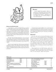
An air spring is a carefully designed rubber/fabric bellows<br />
which contains a column of compressed air. The rubber bellows<br />
itself does not provide force or support load. This is done<br />
by the column of air.<br />
<strong>Firestone</strong> air springs are highly engineered elastomeric bellows<br />
with specially designed metal end closures. Our standard<br />
two ply air spring bellows is actually made up of four layers:<br />
a. An inner liner of calendered rubber.<br />
b. One ply of fabric reinforced rubber.<br />
c. A second ply of fabric-reinforced rubber (with the cords at<br />
a specific bias angle to the first ply).<br />
d. An outer cover of calendered rubber.<br />
Many of our air springs are also available in high strength construction<br />
for higher pressures (see page 14 for more detailed<br />
information). In this case, there are four plies of fabric-reinforced<br />
rubber, with an inner liner and outer cover.<br />
The two ply air spring is standard. Where high strength construction<br />
is available, it is so noted in the selection guide<br />
(page 32), on the individual Data sheets, and in the index<br />
(page 107). If the high strength style number is omitted, then<br />
it is not currently available in that particular part.<br />
Each air spring bellows is identified by a style number. This<br />
style number is molded into the bellows during the curing (or<br />
vulcanization) process. Examples would be 16, 22, 313,<br />
1T15M-6, etc... This identifies only the rubber/fabric bellows<br />
and not the complete assembly. There are several different<br />
end closure options available for most air springs; therefore,<br />
please always specify both the style number and the complete<br />
assembly order number (AON). An example would be: Style<br />
#22, assembly order number W01-M58-6180. Both numbers<br />
are given on the individual data sheets.<br />
5
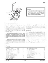
END CLOSURE OPTIONS<br />
Each individual air spring data sheet shows a cross sectional<br />
view of the most popular end closure option for that part. For<br />
convoluted air springs 16 inches in diameter and less, and for<br />
the reversible sleeve air springs, the Crimped Bead Plate<br />
CONVOLUTED AIR SPRINGS<br />
(#22 is shown)<br />
CRIMPED BEAD PLATES<br />
attachment is shown. For convoluted air springs 17 inches in<br />
diameter and larger, a Bead Ring attachment is shown. An air<br />
spring of each variety, with proper terminology for each, is<br />
shown on the following pages.<br />
AIR INLET<br />
1/4" NPT is standard. 3 /4" NPT is also available for most<br />
parts. (See the data sheet order block on each specific<br />
part).<br />
BLIND NUT<br />
3/8-16 UNC thread x 5 /8" deep (two or four per each plate<br />
depending on part size). Used for mounting the part.<br />
UPPER BEAD PLATE<br />
(9 gauge carbon steel, .149"). Permanently crimped to<br />
bellows to form an airtight assembly which allows for leak<br />
testing before the unit leaves the factory. Zinc/chromate<br />
plated for rust protection.<br />
GIRDLE HOOP<br />
Wire wound type shown, molded into the bellows.<br />
BELLOWS<br />
Wall gauge is approximately 1 /4". See page 5 for detailed<br />
information.<br />
LOWER BEAD PLATE<br />
Usually the same as upper bead plate, except without air<br />
inlet.<br />
REVERSIBLE SLEEVE<br />
AIR SPRINGS<br />
(1T15M-6 is shown)<br />
THREADED HOLE May be used for attachment to<br />
mounting surface. Not included in some pistons (See<br />
individual data sheets for specific part configuration.)<br />
AIR INLET 1 /4" NPT is standard. 3 /4" NPT is also available<br />
for most parts. (See the data sheet order block on<br />
each specific part).<br />
BLIND NUT 3 /8-16 UNC thread x 5 /8" deep (two or four<br />
per each plate depending on part size). Used for mounting<br />
the part.<br />
BEAD PLATE (9 gauge carbon steel, .149").<br />
Permanently crimped to bellows to form an airtight assembly<br />
which allows for leak testing before the unit leaves the<br />
factory. Zinc/chromate plated for rust protection.<br />
BELLOWS Wall gauge is approximately 1 /4". See page 5<br />
for detailed information.<br />
BELLOWS END CLOSURE—(steel) Permanently<br />
molded into the bellows (Except for styles 1T19L-7,<br />
1T19L-11).<br />
PISTON May be made of aluminum, steel, plastic or<br />
hard rubber. Held to the bellows by a bolt which screws<br />
into the bumper stud. For mounting, a long bolt may be<br />
used coming up through the mounting surface. Or, a<br />
short bolt may be used to attach the piston to the lower<br />
end closure and then use the threaded holes in the piston<br />
to secure the assembly to the mounting surface. (A<br />
piston long bolt is usually not included).<br />
BUMPER STUD A permanent part of the bellows end<br />
closure (and bellows). It has two functions:<br />
1. The optional rubber bumper snaps over the outside.<br />
2. The inside is a threaded hole (see data sheets for<br />
thread dimension and depth) used to secure the<br />
piston to the bellows.<br />
6
CRIMPED BEAD PLATE<br />
MOUNTING HARDWARE<br />
CRIMPED BEAD PLATE AIR SPRINGS Use the blind<br />
nuts for attachment. This is accomplished by bringing bolts<br />
(two or four depending upon air spring size) through the<br />
3/8-16 UNC<br />
Blind Nut,<br />
5/8" Deep<br />
customer supplied mountIng plate and tightening into the<br />
blind nut. If this bolt is too long, it may fracture the bottom<br />
out of the blind nut.<br />
To <strong>Air</strong> Supply<br />
5/8"<br />
5/8"<br />
Customer Supplies<br />
Mounting Plates<br />
Bolts & Washers<br />
Tightening Torque<br />
on the blind nut: 15 to 20 ft.-lbs.<br />
STUD ADAPTER<br />
1/2-13 UNC Thread<br />
1.35<br />
If a protruding bolt rather than a blind nut is preferred to<br />
attach the air spring, a STUD ADAPTER is available from<br />
<strong>Firestone</strong>:<br />
3/8-16 UNC Thread<br />
1.35<br />
Customer Supplies<br />
Mounting Plates<br />
Nuts & Washers<br />
TANK VALVE One method for inflating air springs<br />
(primarily used in <strong>Air</strong>mount isolator applications) is with<br />
a tank valve: An air hose chuck is used (as inflating a<br />
tire with an air line). Care must be taken to periodically<br />
check the pressure within the air spring, because air<br />
will slowly permeate through the rubber/fabric bellows<br />
(See page 25).<br />
7
END CLOSURE OPTIONS<br />
STEEL BEAD RINGS<br />
CONVOLUTED AIR SPRINGS<br />
(#22 is shown, with bead rings instead of<br />
crimped bead plates)<br />
MOUNTING PLATE is not included. See page 10 for<br />
material, machining recommendations, and installation<br />
instructions.<br />
BEAD RING BOLT May be one of three varieties. See<br />
page 10. Also refer to the data sheet order block on each<br />
individual part for bolt lengths.<br />
NUTS AND LOCKWASHERS are included with the part.<br />
(Except for socket head type bead rings).<br />
BELLOWS Wall gauge is approximately 1 /4". See page 5<br />
for detailed information.<br />
GIRDLE HOOP Wire wound type shown, molded into the<br />
bellows.<br />
BEAD RING, upper and lower. Countersunk steel type<br />
shown. See page 10. Also refer to the data sheet order<br />
block on each part for type and material. See the selection<br />
guide on page 32 for bolt circle diameter and number<br />
of bolts (each ring).<br />
REVERSIBLE SLEEVE AIR SPRINGS<br />
(1T15M-6 is shown, with a bead ring<br />
instead of a crimped bead plate)<br />
MOUNTING PLATE is not included. See page 10 for<br />
material, machining recommendations, and installation<br />
instructions.<br />
BEAD RING BOLT May be one of three varieties. See<br />
below. Also refer to the data sheet order block on each<br />
individual part for bolt lengths.<br />
NUTS AND LOCKWASHERS are included with the<br />
part. (Except for socket head type bead rings).<br />
BEAD RING Countersunk steel type shown. See the<br />
selection guide on page 32 for bolt circle diameter and<br />
number of bolts (each ring).<br />
BUMPER STUD A permanent part of the bellows end<br />
closure (and bellows). It has two functions:<br />
1. The optional rubber bumper snaps over the<br />
outside (of it).<br />
2. The inside is a threaded hole (see data sheets for<br />
thread dimension and depth) used to secure the piston<br />
to the bellows.<br />
THREADED HOLE May be used for attachment to<br />
mounting surface. Not included in some pistons (See<br />
individual data sheets for specific part configuration.)<br />
8
END CLOSURE OPTIONS<br />
LARGE PARTS WITH ALUMINUM BEAD RINGS<br />
All of the parts that are shown with crimped bead plates<br />
are also available with bead rings. (Bead plates are not<br />
suitable for some applications.) Typical examples of<br />
where bead rings are often used follow:<br />
1. Where parts are stacked to increase stroke<br />
(See page16).<br />
2. Where the air spring is being used as a boot or<br />
flexible connector (See page 29).<br />
3. When used as an <strong>Air</strong>mount isolator with an auxiliary<br />
reservoir (See page 24).<br />
4. When air must move in or out of the unit at an extremely<br />
fast rate (and a 3 /4" NPT air inlet is too small).<br />
5. When used with an internal shaft, to either guide the<br />
part or to pull (rather than push) a load.<br />
CONVOLUTED AIR SPRINGS<br />
(#203 is shown)<br />
BEAD RING BOLT May be one of three varieties. See<br />
page 10. Also refer to the data sheet order block on each<br />
individual part for bolt lengths.<br />
NUTS AND LOCKWASHERS are included with the part.<br />
(Except for socket head type bead rings).<br />
MOUNTING PLATE is not included. See page 10 for<br />
material, machining recommendations, and installation<br />
instructions.<br />
BEAD RING, upper and lower. (Aluminum)<br />
GIRDLE HOOP Solid steel type shown, molded into the<br />
bellows.<br />
BELLOWS Wall gauge is approximately 1 /4". See page 5<br />
for detailed information.<br />
9
END CLOSURE OPTIONS<br />
THE THREE FOUR TYPES OF BEAD RINGS<br />
COUNTERSUNK STEEL<br />
RIBBED NECK<br />
SOCKET HEAD<br />
BEAD RING<br />
ALUMINUM<br />
ALUMINUM BEAD RING*<br />
BEAD RING<br />
Used on<br />
4.5 in.<br />
Bolt<br />
Circles<br />
Use M6<br />
Cap<br />
Screws,<br />
(Not<br />
Included)<br />
Bolt<br />
Bolt<br />
Length<br />
Length<br />
Customer<br />
Supplies Plate<br />
Effective<br />
Customer<br />
Effective<br />
Length<br />
Supplies<br />
Length<br />
Plate<br />
Standard Bolt Length (in.)<br />
Standard Bolt Length (in.)<br />
1 3 1/4 5 /8 1 7 /8<br />
Standard Effective Length (in.)<br />
Standard Effective Length (in.)<br />
1.22 1.28<br />
Standard Order Number<br />
Standard Order Number<br />
(bolt only)<br />
(bolt only)<br />
WC1-358-3625<br />
WC1-358-3620<br />
Thread<br />
/16-24 UNF Thread<br />
/8-24 UNF<br />
Customer<br />
Supplies Plate<br />
Optional Shorter Length<br />
Ribbed Neck Bolt<br />
Tightening Torque (ft.-lbs.)<br />
Tightening Torque (ft.-lbs.)<br />
17 to 22 28 to 32<br />
When using bead rings, THE CUSTOMER WILL NEED<br />
TO FABRICATE HIS OWN MOUNTING PLATES. Hot or<br />
cold rolled steel provides satisfactory mounting surfaces,<br />
with specific finishes of 250 32 micro-inches, microns, if machined if in aincir-<br />
cular fashion, and and 250 32 micro-inches microns when ground ground. (side<br />
a<br />
circular<br />
to The side). thickness The thickness of mounting of mounting plates plates depends depends upon upon the<br />
the application. The The plates must be bestrong enough and<br />
backedby by structural members to prevent to prevent bowing bowing (of the<br />
plates) (of the when plates) subjected when subjected to the forces to theor forces loads involved. or loads<br />
The involved. rubberThe bellows rubber provides bellows its provides own seal; its therefore, own seal; ‘O’<br />
rings therefore, other ‘O’ rings sealants or other are not sealants needed arewhen not needed installing when the<br />
part. installing the part.<br />
INSTALLATION<br />
Follow this technique for assembling a bead ring style bellows<br />
to the mounting plate:<br />
a. Insert the bolts into the bead ring (the bead rings have<br />
been previously attached to the bellows at the factory).<br />
The boltswill will be be pulled pulled into into place place by theby action the of action tightening<br />
tightening the nuts. the nuts.<br />
b. Slip all of the bolts (which are protruding through the<br />
bead ring) into the mating holes of the mounting plate<br />
and attach the lockwashers and nuts. FINGER TIGHTEN TIGHTof<br />
EN all nuts all nuts to produce to produce a uniform a uniform gap gap between between the bead the bead ring<br />
ring and and mounting mounting plate plate all the allway the way around. around.<br />
BEAD RINGS CONTINUED<br />
c. At this point, make certain that that the bellows the bellows bead bead is prop-<br />
is<br />
properly seated seated under under the bead the bead ring. ring.<br />
PLEASE NOTETHAT THAT UNIFORM UNIFORM SUCCESSIVE SUCCESSIVE TIGHT-<br />
TIGHTENING OF THE OFNUTS THE NUTS IS IMPORTANT IS IMPORTANT TO SEAT TO SEAT THE<br />
RUBBER THE RUBBER BEAD BEAD PROPERLY TO TO THE MOUNTING<br />
PLATE FOR ITS FULL CIRCUMFERENCE.<br />
Continue with the following sequence:<br />
d. Tighten all nuts one turn each, moving around the circle<br />
until continuous contact is made between the bead ring<br />
and mounting plate.<br />
e. Torque all nutsto tothe the torque specifications shown shown on the on<br />
page, the page, going going at least at least two two complete complete turns turns around around the bolt the<br />
circle. bolt circle.<br />
MATERIAL<br />
Bead rings are supplied in either steel or aluminum. Both<br />
the bead ring material and type of ring are called out in the<br />
description section of the order block on each individual<br />
data page. Also, the bolt length (for the bolts supplied with<br />
that particular order number) is given.<br />
WHERE A BEAD PLATE PART IS SHOWN AND THE<br />
BEAD RING ATTACHMENT IS PREFERRED, PLEASE<br />
REFER TO THE SELECTION GUIDE ON PAGE 32 FOR<br />
BOLT CIRCLE DIAMETERS AND NUMBER OF BOLTS<br />
(EACH RING).<br />
10<br />
*Available only on style #16, #25, and #255-1.5
END CLOSURE OPTIONS<br />
LARGE CONVOLUTED AIR SPRINGS<br />
(#203 is shown, with rolled plates instead of bead rings)<br />
LARGE PARTS WITH ROLLED PLATES<br />
The convoluted parts, with 17, 20, and 22 inch diameter,<br />
are shown with bead rings as standard. We have developed<br />
a method for permanently attaching plates to these<br />
larger sized <strong>Air</strong>strokes (called rolled plate assembly).<br />
These parts may be an advantage over the bead ring<br />
parts in some cases, because installation is much easier<br />
(they attach the same way as the bead plate parts).<br />
When installing the rolled plate parts, a backup plate as<br />
large in diameter as the bead plate must be used. This<br />
plate should be a minimum of 1 /2 inch thick.<br />
Again, for the blind nut and air entrance locations of rolled<br />
plate parts (bead rings are shown as standard on the<br />
data pages), please refer to the selection guide on page<br />
32. The static data chart on each individual part may be<br />
used for the rolled plate version; but, two modifications<br />
must be made:<br />
1. Increase the minimum height by .70 inch.<br />
2. Add .70 inch to the height (bottom axis) before<br />
reading loads.<br />
AIR INLET 3 /4 NPT is standard. See the selection guide<br />
on page 32 for location (type 5). A centered 2" NPT air<br />
inlet is also available for some rolled plate parts. (Consult<br />
<strong>Firestone</strong>).<br />
BLIND NUT 1 /2-13 UNC thread x 3 /4" deep (four each<br />
plate). Used for mounting the part. A stud adapter for this<br />
size blind nut is not available.<br />
UPPER BEAD PLATE (6 gauge carbon steel, .149").<br />
Permanently crimped to bellows to form an airtight assembly.<br />
Allows for leak testing before the unit leaves the<br />
factory. Zinc/chromate plated for rust protection.<br />
.35 in.<br />
CLAMP RING This ring is crimped up under the bellows<br />
bead to permanently attach the bead plate to the<br />
bellows. It is also zinc/chromate plated for rust<br />
protection.<br />
LOWER BEAD PLATE Usually the same as upper<br />
bead plate, except without air inlet. See the selection<br />
guide on page 32 for diameter (type 5).<br />
11
HOW TO USE<br />
THE STATIC DATA CHART<br />
We also refer to this chart as the load/deflection<br />
(L/D) curve for an air spring. The force [1] is given<br />
on the right hand axis vs. the air spring height [2]<br />
as shown along the bottom axis; thus, load vs.<br />
deflection. The internal volume [3] is also given<br />
along the left hand axis, again vs. height [2]. It is<br />
called static data because the air spring is in a<br />
static, or non-moving, constant pressure condition.<br />
In almost all cases the static curves were run<br />
using a two ply bellows; however, where a four<br />
ply bellows is available, use the two ply chart for it<br />
also.<br />
AIRSTROKE ACTUATION<br />
The important considerations are minimum<br />
height [4] (3.0 inches) and maximum recommended<br />
height [5] (10.1 inches). Subtracting one<br />
from the other gives the stroke potential for this<br />
part (10.1 – 3.0 = 7.1 inches). As an actuator, the<br />
entire stroke may be used, or any potion thereof.<br />
Ignore recommended airmount design height [6]<br />
and the corresponding darkened line [7]. This<br />
height is important in using the air spring as an<br />
isolator (AIRMOUNT). It has nothing to do with<br />
the concern here of actuation. To determine the<br />
force at any given height, simply move up the<br />
height line to where it intersects any of the static<br />
pressure curves. Then move to the right and<br />
read from the force scale [1].<br />
EXAMPLE: At 80 psig, what is the force using a<br />
#22 from 4.0 to 9.0 inches, or 9.0 – 4.0 = 5.0 inch<br />
stroke? See [8] for force at 4.0 inches (7,180 #)<br />
and [9] for force at 9.0 inches (4,670 #). This<br />
example illustrates the primary difference<br />
between <strong>Firestone</strong> <strong>Air</strong>strokes and conventional<br />
air cylinders. <strong>Air</strong> cylinders have a constant area<br />
for the pressure to work against, or constant<br />
effective area. the effective area and force of an<br />
air spring changes as the height changes.(There<br />
is one exception: notice the plateau section of<br />
reversible sleeve 1T type curves.)<br />
VOLUME (WITHOUT BUMPER) CU IN. x 100<br />
[3]<br />
11<br />
10<br />
9<br />
8<br />
752<br />
7<br />
6<br />
5<br />
4<br />
349<br />
3<br />
2<br />
1<br />
[6]<br />
Recommended<br />
<strong>Air</strong>mount<br />
Design Height<br />
9.5 Inches<br />
Do not use <strong>Air</strong>stroke in<br />
shaded area without<br />
consulting <strong>Firestone</strong><br />
[13]<br />
[10]<br />
[7]<br />
[15]<br />
[14]<br />
Volume<br />
100 Psig<br />
[12]<br />
[9]<br />
Static Data<br />
1227<br />
120<br />
100<br />
80<br />
60<br />
40<br />
20 Psig<br />
[8]<br />
[11]<br />
11<br />
10<br />
9<br />
8<br />
77,180<br />
6<br />
5<br />
4,670<br />
4,280<br />
4<br />
MAX. HT. [5]<br />
MIN. HT.<br />
[16]<br />
[4]<br />
12 11 10 9 8 7 6 5 4 3<br />
[2] Bumper Contact<br />
HEIGHT IN.<br />
(4.2 IN.)<br />
3<br />
2<br />
1<br />
FORCE LBS x 1000<br />
[1]<br />
12
In the example the effective area of a #22, at 4.0 inches using<br />
the 80 psi curve, is:<br />
7,180 lbs.<br />
80 Ibs/in 2 = 89.8 in 2<br />
at 9.0 inches in height it is:<br />
4,670 lbs.<br />
80 Ibs/in 2 = 58.4 in 2<br />
An air cylinder with 89.8 in 2 of area would have an 80 psi curve<br />
as shown by dotted line [10].<br />
The volume curve [3] may also be of importance:<br />
a. If one needs to know the amount of free air (then compressed<br />
by the compressor) to perform a desired operation.<br />
b. If the actuation must be completed quickly and calculations<br />
of flow through the air inlet (orifice) are required.<br />
In each case above, the change in internal volume is required.<br />
Read up from the two heights involved to the intersecting point<br />
with the volume curve. Then move to the left and read from the<br />
volume scale. In the example at 4.0 a #22 (notice most volume<br />
curves are at 100 psig) has an internal volume of 349 in 3 [11]<br />
and at 9.0 the volume is 752 in 3 [12]. The change in volume is<br />
then 752 in 3 – 349 in 3 , or 403 in 3 . The volume at minimum<br />
height (349 in 3 ) would not be subtracted if exhausting the air<br />
spring to atmospheric pressure.<br />
Notice the shaded area [13]. We do not recommend that an<br />
air spring be used at heights extending into this section. The<br />
“beginning of the shaded area” for a #22 is at 101 inches [5].<br />
SEE PAGE 15 FOR A MORE DETAILED DISCUSSION OF<br />
ACTUATION.<br />
AIRMOUNT ISOLATION<br />
Because of lateral stability considerations (see page 23 for<br />
more details) we recommend that each air spring be used at a<br />
specific height when used as an isolator. This specific height is<br />
called the “<strong>Air</strong>mount design height” [6]. The vertical line running<br />
through this height [7] is darkened so that it is easy to see<br />
where it intersects the static curves for load readings.<br />
EXAMPLE: Support a 4,100 pound load with an air spring.<br />
Would a #22 be appropriate, and if so, at what height? The<br />
height isn’t much of a problem, as this part SHOULD BE<br />
USED AT 9.5 INCHES. Simply move up the darkened line to<br />
where it intersects 4,100 Ibs [14]. That point falls between the<br />
80 and 60 psig curves. Exactly what pressure would be<br />
required? Use the formula:<br />
Effective Area =<br />
Load (Ibs.)<br />
Pressure (Ibs/in 2 )<br />
Determine the effective area at 9.5 inches (using the 80 psig<br />
curve, since 80 psig would be closer to our exact pressure<br />
than 60 psig), or:<br />
Effective Area = 4,280 Ibs. [15] = 53.5 in 2<br />
80 Ibs/in 2<br />
Then divide the actual load by the effective area:<br />
4,100 Ibs. = 76.6 PSIG<br />
53.5 in 2<br />
The pressure required to support 4,100 Ibs. with a #22 at a<br />
design height of 9.5 inches is therefore 76.6 PSIG.<br />
Please note that the static data can be converted to dynamic<br />
data (the air spring is in motion) by applying the formulas that<br />
are presented in the <strong>Air</strong>mount isolation section on page 22.<br />
SEE PAGE 21 FOR A MORE DETAILED DISCUSSION OF<br />
VIBRATION ISOLATION.<br />
INTERNAL RUBBER BUMPERS<br />
Some parts are available with internal rubber bumpers. Where<br />
a bumper is available, it is shown as a dotted line in the cross<br />
sectional view of the air spring. Additionally, please note that:<br />
1. the minimum height is increased to the “bumper contact”<br />
point [16] (this reduces the total available stroke somewhat,<br />
by 4.2 – 3.0 = 12 inches in our #22 example), and<br />
2. the order block contains the proper ordering numbers for<br />
parts with bumpers.<br />
13
BASIC PARAMETERS APPLICABLE TO<br />
<br />
BOTH AIRSTROKE ACTUATORS AND<br />
<br />
AIRMOUNT ISOLATORS<br />
MEDIA<br />
<strong>Air</strong> springs are designed for use with compressed air. Nitrogen<br />
is also acceptable. <strong>Air</strong> springs may be filled with water or waterglycol<br />
(automotive antifreeze) solutions. If water is to be used,<br />
rust inhibitors should be added to protect the end closures. Two<br />
reasons for liquid filling an air spring are:<br />
1. To reduce the internal volume of air (and therefore, increase<br />
the natural frequency of the air spring) and,<br />
2. To use a media which is incompressible. Accurate positioning<br />
would be one reason to do this.<br />
Petroleum base fluids (most hydraulic oils fall into this category)<br />
are NOT RECOMMENDED. Moderately lubricated air will not<br />
harm the bellows.<br />
PRESSURE<br />
1. 100 PSIG MAXIMUM FOR 2 PLY.<br />
2. 175 PSIG MAXIMUM FOR HIGH STRENGTH.<br />
We recommend that there be a minimum three times safety factor<br />
between maximum internal air pressure and burst pressure.<br />
So, as an example, if 100 psig is required, the burst should be at<br />
300 psig or greater. For convoluted air springs, the burst pressure<br />
decreases as height increases. Therefore, the determining<br />
factors are twofold: What is the maximum height into extension<br />
and what is the internal pressure at that point? Please see the<br />
<strong>Air</strong>stroke Inflation Pressure Chart (for single, double, and triple<br />
convoluted air springs) on page 17 for specific pressure vs.<br />
height information.<br />
For AIRMOUNT applications (where the part is used at a<br />
height very close to the shaded area), it is best to stay within<br />
100 psig maximum for a two ply, and 150 psig maximum for a<br />
four ply or high strength cord air spring.<br />
STORAGE<br />
The best storage environment is a dark, dry area at normal<br />
room temperature.<br />
TEMPERATURE<br />
1. STANDARD BELLOWS. Our standard industrial air springs<br />
should be limited to use in the range:<br />
– 35° F to + 135° F.<br />
2. ALL NATURAL RUBBER (LOW TEMPERATURE COM-<br />
POUND). A few of our industrial air springs are available in<br />
all natural rubber construction. This increases the acceptable<br />
cold or low end of the scale to – 65° F. The range then<br />
becomes – 65° F to +135° F.<br />
3. EPICHLOROHYDRIN (HIGH TEMPERATURE COM-<br />
POUND). Most convoluted parts are available in this<br />
material. The operating temperature range for it is: 0° F to<br />
225° F. Additionally, Epichlorohydrin has very good oil resistance.<br />
ALL EPICHLOROHYDRIN APPLICATIONS MUST<br />
BE APPROVED BY FIRESTONE. For more information on<br />
Epichlorohydrin (also known as Herclor), ask for<br />
Technigram number 111.<br />
4. NEOPRENE (HIGH TEMPERATURE COMPOUND).<br />
Neoprene is more resistant to damage from oil. For this<br />
reason, <strong>Firestone</strong> Neoprene has been used as the inside<br />
layer in two configurations to reduce the hazard of having oil<br />
in the pneumatic plumbing system. The third configuration<br />
includes an outer layer of <strong>Firestone</strong> Neoprene for applications<br />
that expose the exterior of the air spring to an oil<br />
environment. In addition, <strong>Firestone</strong> Neoprene is able to<br />
withstand higher temperatures than natural rubber (-35º to<br />
+165º F).<br />
CONTAMINATES<br />
Shielding should be used to protect the bellows from exposure<br />
to hot metal, sand, petroleum base fluids, acids, etc. Please<br />
consult <strong>Firestone</strong> if you wish to know how the bellows will withstand<br />
a specific contaminant (For liquids such as acids, it is<br />
important to know both concentration and temperature).<br />
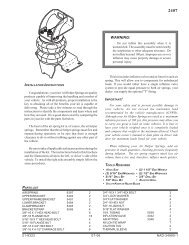
WARNING<br />
DO NOT INFLATE ASSEMBLY WHEN IT IS UNRESTRICTED. ASSEMBLY<br />
MUST BE RESTRICTED BY SUSPENSION OR OTHER ADEQUATE STRUC-<br />
TURE. DO NOT INFLATE BEYOND PRESSURES RECOMMENDED IN<br />
DESIGN LITERATURE (CONTACT FIRESTONE FOR INFORMATION).<br />
IMPROPER USE OR OVERINFLATION MAY CAUSE ASSEMBLY TO<br />
BURST CAUSING PROPERTY DAMAGE OR SEVERE PERSONAL INJURY.<br />
14
AIRSTROKE ACTUATION<br />
SELECTION<br />
1. Refer to the selection guide on page 32 for <strong>Air</strong>stroke force<br />
and stroke capabilities. After your list of possibilities has been<br />
reduced to one or two air springs, then turn to the individual<br />
data page for more detailed information on those parts.<br />
2. STROKE: The maximum STROKE CAPABILITY is the difference<br />
between the height corresponding to the “start of<br />
the shaded area” minus the minimum height. This entire<br />
stroke, or any portion thereof, may be used. If an internal<br />
rubber bumper is required, please note that the minimum<br />
height is increased, and therefore, the total stroke is<br />
decreased.<br />
3. FORCE: Read the forces directly from the static data chart,<br />
or, use the force table located under the chart. Notice that<br />
the force generally decreases as height increases. This feature<br />
is discussed in detail on page 12 in the section entitled<br />
“How to Use the Static Data Chart.”<br />
4. SELECT THE END CLOSURES AND AIR INLET SIZE:<br />
Most <strong>Air</strong>stroke actuators are available with permanently<br />
attached plates or bead ring attachments. If an alternate end<br />
closure option is available, it is so stated under the cross<br />
sectional view of the part. Please refer to page 6 for a<br />
detailed discussion of end closure options.<br />
DOWN AND UP STOPS<br />
Positive stops in both directions (compression and extension)<br />
should always be used with <strong>Air</strong>stroke actuators .<br />
1. In COMPRESSION, the minimum height shown for each air<br />
spring is at, or slightly above the PINCH POINT of the bellows.<br />
Here is a #22 shown in the collapsed or “pinch point” condition:<br />
2. In EXTENSION, an upstop is required to prevent the air<br />
spring from overextending at heights into the shaded area of<br />
the graph. The reasons for this are twofold: a) the life of the<br />
bellows may be reduced and b) the crimp may open up,<br />
allowing the bellows bead to blow out of the metal end closure.<br />
There are many ways to design-in an upstop, including<br />
a. a chain,<br />
b. a cable,<br />
c. contacting a metal stop, etc.<br />
RETURN<br />
An <strong>Air</strong>stroke actuator is a single acting device. To return the<br />
<strong>Air</strong>stroke to its minimum height (for another cycle or stroke),<br />
some return force must be used. Gravity acting on the load<br />
may be all that’s required. The force to collapse the convoluted<br />
type <strong>Air</strong>strokes to minimum height is given in the order block<br />
section for each part. If the load is not sufficient, then a second<br />
<strong>Air</strong>stroke or coil spring may be required.<br />
GUIDING<br />
An <strong>Air</strong>stroke follows the path of least resistance; therefore, the<br />
actuator should be guided in most instances. This is often easily<br />
accomplished in the mounting geometry.<br />
ANGULAR CAPABILITY<br />
An <strong>Air</strong>stroke actuator can stroke through an arc (without a clevis).<br />
Angular motion of up to 30 degrees is possible. When<br />
using an actuator with the mounting plates at an angle to each<br />
other, observe the following:<br />
a. Measure force at the height between the plate centers.<br />
b. Measure maximum height at the side separated<br />
the furthest.<br />
c. Measure minimum height at the side collapsed the most.<br />
3.0<br />
The bellows can be damaged if allowed to constantly bottom<br />
out as shown above; therefore, a downstop is required<br />
to prevent this. An external downstop can be something as<br />
simple as a steel block and should be sized at or slightly<br />
greater than the minimum height of the <strong>Air</strong>stroke. In our #22<br />
example, the block would need to be at least 3.0 inches<br />
high. If an external downstop cannot be used, many parts<br />
are available with internal rubber bumpers (shown as a<br />
dotted line in the cross-sectional view of the air spring<br />
where available).<br />
15
Angular Capability continued<br />
These measurements must fall within the guide lines for that<br />
particular part. Consider style #22 in the following scissors<br />
arrangement:<br />
Please note that the air spring forces are not additive in this<br />
configuration. A method for guiding, which also illustrates one<br />
center ring concept for mounting the two parts together at the<br />
middle, is illustrated below:<br />
Calculate<br />
Force Here<br />
Max Ht<br />
(Must be ≥ 3.0)<br />
Max Ht<br />
#22<br />
(Must be ≤ 10.1)<br />
Center Ring<br />
Pivot<br />
Point<br />
Reversible sleeve Type 1T parts may also stroke through an<br />
arc. In this case, care must be taken to prevent the bellows from<br />
rubbing (internally) against itself where it rolls over the piston:<br />
Customer Must<br />
Supply Button<br />
Head-Socket Head<br />
Cap Screws<br />
Bellows must<br />
not rub against<br />
itself here.<br />
HORIZONTAL MISALIGNMENT<br />
The upper and lower bead plate centers (or mounting plate<br />
centers in the case of a bead ring type attachment) may be out<br />
of line somewhat without injury to the bellows. Our “rule of<br />
thumb” for convoluted type <strong>Air</strong>strokes is one inch misalignment<br />
allowed per convolution. So, a single convoluted air spring<br />
may be out of line by as much as 1 inch, a double by 2 inches,<br />
and a triple convoluted air spring by 3 inches.<br />
DESIGN ENVELOPE<br />
Adequate clearance should be provided around the <strong>Air</strong>stroke<br />
to prevent puncturing or rubbing of the bellows. The maximum<br />
diameter @ 100 psig for each <strong>Air</strong>stroke (bellows) is located<br />
just above the cross-sectional view of the air spring.<br />
STACKING<br />
It is permissible to stack <strong>Air</strong>strokes (one on top of another) to<br />
increase stroke; however, the center plate (or plates) connecting<br />
the two or more <strong>Air</strong>strokes MUST BE GUIDED.<br />
FAIL SAFE DEVICES<br />
Some applications require the use of fail safe mechanisms<br />
(such as a mechanical lock-out on a scissors lift) to prevent<br />
damage or injury in the event of an air system failure.<br />
VACUUM<br />
An <strong>Air</strong>stroke can withstand a small amount of vacuum without<br />
injury to the bellows. The maximum amount of acceptable vacuum<br />
is dependent upon the bellows’ size, the height in use, and<br />
whether it is a two ply or high strength (fabric) air spring. (A high<br />
strength <strong>Air</strong>stroke bellows has a “stiffer” wall than a two ply;<br />
therefore, it is less susceptible to dimpling and deformation<br />
inward). It is generally best to use only single convoluted air<br />
springs under vacuum.<br />
An <strong>Air</strong>stroke Design Parameter Worksheet<br />
can be found on page 105.<br />
16
AIRSTROKE<br />
PRESSURE (PSIG)<br />
INFLATION PRESSURE CHART<br />
MAXIMUM RECOMMENDED INTERNAL PRESSURES FOR CONVOLUTED<br />
TYPE AIRSTROKE ACTUATOR APPLICATIONS<br />
BASED ON APPROXIMATELY 1/3 NORMAL BURST VALUES<br />
APPLICATIONS WHICH EXCEED THESE LIMITS SHOULD BE REVIEWED WITH FIRESTONE.<br />
CONSTRUCTION BEAD PLATE AND<br />
BEAD PLATE AND BEAD RING STYLE<br />
ROLLED PLATE STYLE<br />
REFER TO EACH<br />
INDIVIDUAL DATA<br />
PAGE FOR MAXIMUM<br />
USABLE HEIGHT<br />
RESTRICTIONS<br />
HIGH STRENGTH<br />
TWO PLY<br />
BEAD RING STYLE<br />
18 16.5 15 13.5 12 10.5 9 7.5 6 4.5<br />
TRIPLE CONVOLUTED<br />
12 11 10 9 8 7 6 5 4 3<br />
DOUBLE CONVOLUTED<br />
6.5 6 5.5 5 4.5 4 3.5 3 2.5 2<br />
SINGLE CONVOLUTED<br />
OVERALL AIRSTROKE HEIGHT (INCHES)<br />
250<br />
200<br />
150<br />
100<br />
50<br />
0<br />
17
AIRSTROKE<br />
ACTUATOR PROBLEM SOLVERS<br />
GATE VALVE OPERATOR<br />
GLUING PRESS<br />
WEB TENSIONING DEVICE<br />
DIE STRIPPER<br />
AIRSTROKE<br />
ACTUATOR<br />
PAPER<br />
KNIFE SPRING ACTUATOR<br />
QUENCH TANK ACTUATOR<br />
ROTATION<br />
LOG<br />
KNIFE<br />
QUENCH TANK<br />
AIRSTROKE ACTUATORS<br />
UPPER & LOWER POSITIVE STOPS<br />
PAPER SIZING PRESS<br />
PICKLING TANK ACTUATOR<br />
PRESS<br />
AIR LINES<br />
PIVOT<br />
ACID TANK<br />
ACID<br />
FRAME<br />
WIRE COILS<br />
QUICK LOCK DEVICE<br />
PRESSURE ROLL FOR CALENDER<br />
18
AIRSTROKE<br />
ACTUATOR PROBLEM SOLVERS<br />
MISSILE ASSEMBLY FIXTURE<br />
CORE STRAIGHTENER<br />
AIRSTROKE<br />
ACTUATOR<br />
BELT TAKE UP<br />
ROLLER FRICTION BRAKE<br />
FRICTION PAD<br />
AIRSTROKE<br />
ACTUATOR<br />
PIPE INDEXING THREADING<br />
END VIEW OF PIPE<br />
OSCILLATING DOCTOR FOR PAPER<br />
CALENDER ROLL<br />
DOCTOR<br />
CYLINDER<br />
FORMING PRESS<br />
CABLE TENSIONING DEVICE<br />
PRESS<br />
PLATEN<br />
BAG FLATTENER<br />
TORSIONAL FRICTION BRAKE<br />
BAG OF<br />
MATERIAL<br />
TO BE<br />
FLATTENED<br />
POWERED<br />
ROLLER<br />
DRIVE<br />
BELT<br />
LINESHAFT<br />
AIRSTROKE<br />
ACTUATOR<br />
ROLLER<br />
SUPPORT<br />
FRAME<br />
TORQUE TUBE<br />
AIRSTROKE<br />
ACTUATORS<br />
BRAKE BUSHING<br />
19
AIRSTROKE<br />
ACTUATOR PROBLEM SOLVERS<br />
AIRSTROKE<br />
ACTUATOR<br />
HINGED GATE<br />
AIR<br />
FITTING<br />
HOT FOIL STAMPING PRESS<br />
AIRSTROKE<br />
ACTUATOR<br />
COMPRESSED POSITION<br />
EXTENDED POSITION<br />
WEIGH<br />
HOPPER<br />
TORSION<br />
SPRING<br />
HINGE<br />
CLOSED<br />
OPEN<br />
ACTUATED HEAVY DUTY SEALER<br />
PIVOTED CLAMPING DEVICE<br />
AIRSTROKE<br />
ACTUATOR<br />
AIRSTROKE ACTUATED ROLLER STOP<br />
HINGED ACTUATED GRAVITY GATE<br />
RUBBER<br />
STOP<br />
AIRSTROKE<br />
ACTUATOR<br />
ADJUSTABLE<br />
COLLAPSE<br />
HEIGHT<br />
RETURN TENSION<br />
SPRING<br />
AIRSTROKE<br />
ACTUATOR<br />
VERTICAL ACTUATED DRIVE TABLE<br />
SCISSOR LIFT<br />
TOP OF CHAIN IN HIGH POSITION<br />
TOP OF CHAIN IN LOW POSITION<br />
AIRSTROKE<br />
ACTUATOR<br />
FIXED STOP<br />
CASE PACKER<br />
CONVEYOR TRANSFER ACTUATOR<br />
20
AIRMOUNT<br />
SELECTION AND ISOLATION FORMULA<br />
Refer to the selection guide on page 33 for <strong>Air</strong>mount load and<br />
isolation capabilities. Follow this procedure:<br />
1. LOAD CAPACITY<br />
Select one or two <strong>Air</strong>mounts that can support the load at each<br />
mounting point. It is normally best to design for pressures in<br />
the 60 to 80 psig range. Consider only the 1M1A-0 and the<br />
single and double convoluted types at first. Please notice that<br />
in the range of 210 to 63,890 pounds you will, in most cases,<br />
find both a single and double convoluted style part which will<br />
support the load.<br />
2. DETERMINE ISOLATION EFFECTIVENESS<br />
Select the disturbing frequency that is closest to the actual<br />
forced frequency (400, 800, or 1500 cpm). Then check the percentage<br />
of isolation for the parts that were selected in 1 above.<br />
3. DETERMINE DESIGN HEIGHT<br />
THE AIR SPRING SHOULD BE USED AT THE DESIGN<br />
HEIGHT GIVEN. The double convoluted part is used at a<br />
design height somewhat higher than its single convolution<br />
equivalent. Make sure that the design height falls within the<br />
height restrictions. Also, the double convoluted part will show a<br />
higher percentage of isolation (less transmitted vibration) than<br />
the single convoluted air spring. The reason for this is that the<br />
double convoluted part has a greater internal volume of air<br />
than the single convoluted version of the same size. At disturbing<br />
frequencies in the 400 to 800 cpm range, the double<br />
convoluted part is a significantly better vibration isolator than<br />
the single convoluted part. At disturbing frequencies of 800 to<br />
1500 cpm, the gap closes considerably. At frequencies of<br />
1500 cpm and above, the difference is negligible.<br />
4. DETERMINE EXACT INTERNAL PRESSURE<br />
AND ISOLATION EFFECTIVENESS<br />
The chances are that your specific vibration problem does not<br />
fall neatly into the load and disturbing frequency criteria as presented<br />
in the selection guide.<br />
Therefore, once a preliminary part selection has been made,<br />
turn to the individual data page for that part in order to determine<br />
the specific internal pressure required and the<br />
percentage of isolation attainable.<br />
VIBRATION ISOLATION<br />
CONSIDER THIS EXAMPLE:<br />
Isolate a vibrating screen which weighs a total of 16,400<br />
pounds, preferably with one isolator at each corner. The vibrating<br />
mechanism is rotating at a speed of 850 rpm (cpm) with a<br />
total stroke of 5 /16 inch.<br />
a. Determine the load at each mounting point:<br />
16,400 = 4,100 lbs.<br />
4<br />
Scan down the 80 psig load column in the selection guide. It<br />
appears that either a #19 or a #22 will support the load at a<br />
pressure between 60 and 80 psig.<br />
b. Determine Isolation Effectiveness.<br />
Read the % of Isolation at 800 cpm for the #19 and #22<br />
(since 800 is closest to our machine speed of 850 cpm). A #19<br />
is at 96.0% and a #22 is at 98.2%. Looking at isolation effectiveness<br />
in terms of % TRANSMISSION, the #19 will transmit<br />
100 – 96.0, or 4.0% of the vibrations. A #22 will transmit<br />
100 – 98.2, or 1.8% of the vibrations. So, even though there<br />
does not seem to be much difference between 96.0% and<br />
98.2% isolation, the #22 is in fact a better isolator by approximately<br />
a factor of two when comparing transmitted vibration.<br />
c. Determine Design Height.<br />
Let’s say we have chosen the #22 because 96.0% isolation for<br />
a #19 is considered to be too low. A #22 should be used at 9.5<br />
inches as shown in the second column on page 33.<br />
d. Determine Exact Internal Pressure and Isolation Percentage.<br />
Turn to page 61 for detailed information on the #22.<br />
a) What exact pressure will be required to support the load<br />
of 4,100 Ibs? Refer to the information in the block entitled<br />
“Dynamic Characteristics at 9.5 in Design Height.”<br />
4,280 lbs. = 53.5 in<br />
80 lbs/in 2 = effective area @ 9.5 inches<br />
2<br />
@ 80 psig<br />
Divide the actual load by the effective area:<br />
4,100 lbs. = 76.6 psig required to support<br />
53.5 in 2 4,100 lbs. at 9.5 inches<br />
21
AIRMOUNT<br />
b) What exact isolation will be attained?<br />
Use the formula:<br />
% Transmission = ( )<br />
100<br />
2<br />
f f – 1<br />
f n<br />
Where: f f = Forced Frequency<br />
f n = Natural Frequency<br />
The forced frequency is 850 cpm Read the natural frequency<br />
from the line at the load and pressure closest to the actual situation,<br />
or 106 CPM (@ 80 psig and 4,280 Ibs.):<br />
% Transmission = 100<br />
2<br />
– 1<br />
850<br />
( 106)<br />
% Transmission = 1.6%<br />
% Isolation = 100 – % Transmission<br />
% Isolation = 100 – 1.6<br />
% Isolation = 98.4%<br />
Notice that the natural frequency of an <strong>Air</strong>mount changes only<br />
slightly with variations in pressure and load. Therefore, when<br />
working at pressures other than 40, 60, 80, or 100 psig, % isolation<br />
can be calculated quite accurately using the “closest”<br />
natural frequency and the formula above.<br />
DYNAMIC SPRING RATE FORMULA<br />
Spring rate is a different matter. Unlike most conventional<br />
springs, the rate of an <strong>Air</strong>mount is not constant. It is a function<br />
of the change in effective area, volume, and pressure from<br />
design height. To determine the rate of an <strong>Air</strong>mount, use the<br />
following formula:<br />
[ ( ) ( ) ]<br />
1.38 1.38<br />
V 1 V<br />
K=[[P g +14.7] 1.38 1<br />
1.38<br />
A c V – Ae –14.7(Ac c V e<br />
–A e )] lbs<br />
1inch<br />
WHERE:<br />
K = Vertical Spring Rate in Ibs./inch<br />
P g = Gauge Pressure at design height<br />
lbs<br />
( in ) 2<br />
A c = Effective Area at 1 /2 inch below design height (in 2 )<br />
A e = Effective Area at 1 /2 inch above design height (in 2 )<br />
V 1 = Internal Volume at design height (in 3 )<br />
V c = Internal Volume at 1 /2 inch below design height (in 3 )<br />
V e = Internal Volume at 1 /2 inch above design height (in 3 )<br />
VIBRATION ISOLATION<br />
Consider the same #22 example: What is the vertical spring<br />
rate with a load of 4,100 pounds at a design height of 9.5<br />
inches? Refer to the static data chart on page 62. Again,<br />
our “closest" pressure is 80 psig, so we'll need to read the<br />
appropriate data from the 80 psig curve.<br />
The 80 psig information at 1 /2 inch above design height<br />
would fall at the 10.0 inch height line, and 1 /2 inch below<br />
design height would fall at the 9.0 inch height line. (In this<br />
example, we can read loads from the force table). The<br />
information at design height is located in the “Dynamic<br />
Characteristics Block.” So,<br />
K = Unknown<br />
P g = 76.6 psig (see page 13)<br />
A c = 58.4 in 2 = 4,670 lbs.<br />
( 80 lbs/in)<br />
2<br />
A = 47.6 in 2 = 3,810 lbs.<br />
80 lbs/in 2<br />
e ( )<br />
V 1 = 782 in 3<br />
V c = 752 in 3<br />
V e = 809 in 3<br />
1.38 1.38<br />
K=[ [P V<br />
g +14.7] A 1 V<br />
c 1.38 1 – Ae<br />
1.38 –14.7(Ac –A<br />
V e c V e<br />
)] lbs<br />
1inch<br />
K=[ [76.6+14.7] 58.4 1.38 1.38<br />
782<br />
782<br />
[ ( ) –47.6 ( ) ] –14.7<br />
752 809 (58.4–47.6)<br />
1inch<br />
K = 1,324 lbs/inch<br />
NATURAL FREQUENCY FORMULA<br />
Once the spring rate is determined, calculate the <strong>Air</strong>mount<br />
natural frequency (for an undamped system) as follows:<br />
f n= 188 √ K L<br />
Where:<br />
f n = Natural Frequency in cycles per minute (cpm)<br />
K = Rate (Ibs/inch)<br />
L = Load (pounds)<br />
in our example:<br />
f n= 188 √<br />
1,324<br />
4,100<br />
f n = 106.8 cpm<br />
[ ( ) ( ) ]<br />
22
AIRMOUNT<br />
VIBRATION ISOLATION<br />
Up to this point, only the weight and disturbing frequency have<br />
been discussed. THERE ARE MANY OTHER IMPORTANT<br />
CONSIDERATIONS:<br />
CENTER OF GRAVITY<br />
An <strong>Air</strong>mount isolation system is inherently soft (easily deflected);<br />
therefore, precautions must be taken to insure that the<br />
system is stable. First, consider the location of the center of<br />
gravity (c.g.). Ideally, the <strong>Air</strong>mounts should be located on the<br />
same plane (parallel to the ground) as the center of gravity.<br />
Where this is not possible, follow this guideline: The distance<br />
between the most narrow mounting points should be at least<br />
twice the height of the center of gravity.<br />
Height 48"<br />
Width 46"<br />
Length 50"<br />
LATERAL RATES AND STABILITY<br />
Single and double convoluted air springs SHOULD BE USED<br />
AT THE DESlGN HEIGHTS GIVEN, because that is the point<br />
of maximum lateral rate or stability. The lateral rate decreases<br />
as the <strong>Air</strong>mount height decreases. Consider a #22 again at<br />
80 psig:<br />
Height Lateral Rate Vertical Rate<br />
9.5 inch (design height) 325 lbs/in 1,373 lb/in<br />
8.5 inch 212 lbs —<br />
In the above example, the most narrow distance between two<br />
<strong>Air</strong>mounts is 46 inches The height to the c.g. is 48 inches;<br />
therefore, this system does not meet our guideline. Two possible<br />
solutions would be:<br />
1. Increase the base dimensions to meet our guideline by<br />
increasing both the width and length to at least 48 x 2 or<br />
96 inches.<br />
2. Locate the <strong>Air</strong>mounts at the c.g. as shown above (in the<br />
next column).<br />
7.5 inch Unstable —<br />
Notice that the #22 becomes unstable in the horizontal or lateral<br />
direction when moving down only two inches from design height.<br />
23
AIRMOUNT<br />
At design height and without an auxiliary reservoir, the single<br />
and double convoluted parts follow this pattern; i.e., the lateral<br />
rate varies from 1 /5 to 1 /2 of the vertical rate (only the larger<br />
high strength parts get as high as 1 /2). Notice the #22 is<br />
approximately 1 325<br />
/4( 1,373).<br />
Going back to the original example of<br />
a vibrating screen which weighs 16,400 Ibs. mounted on four<br />
#22’s (@ 9.5 inches), a side load of 1,300 pounds (325 x 4)<br />
would deflect the entire suspended mass by one inch.<br />
TRIPLE CONVOLUTED AND<br />
REVERSIBLE SLEEVE TYPE PARTS<br />
Both of these types are unstable laterally (except for the<br />
1M1A). Due to low natural frequencies, both can be excellent<br />
isolators; however, do not use these two types as <strong>Air</strong>mount<br />
isolators without consulting <strong>Firestone</strong> (for special guidelines<br />
and precautions).<br />
DESIGN ENVELOPE<br />
Adequate clearance should be provided around the <strong>Air</strong>mount to<br />
prevent puncturing or rubbing of the bellows. The maximum<br />
diameter @ 100 psig for each <strong>Air</strong>mount (bellows) is shown just<br />
above the cross sectional view of the air spring.<br />
SAFETY STOPS<br />
It is normally recommended that positive stops be installed in all<br />
directions; i.e., into compression, extension, and laterally.<br />
Positioning of the vertical stops depends upon the amplitude of<br />
movement, both during normal operation and startup and shutdown.<br />
A good “rule of thumb” is ± 1 /2 inch from design height for<br />
vertical stops and also ± 1 /2 inch (horizontally) for lateral stops.<br />
INITIAL INSTALLATION<br />
NEVER use <strong>Air</strong>mounts to lift equipment into place, due to the lateral<br />
instability at lower air spring heights as discussed<br />
previously. Equipment should be rested on stops set slightly<br />
below design height and raised into position for isolation.<br />
STARTUP AND SHUTDOWN/<br />
RESONANCE AND AMPLIFICATION<br />
Resonance is the condition where the forced frequency of the<br />
vibrating system is at the natural frequency of the suspension.<br />
When this happens, AMPLIFICATION of movement occurs.<br />
Going back to our vibrating screen example again, if the normal<br />
stroke is 5 /16 of an inch, during startup and shutdown (as<br />
the machine goes through resonance), the amplitude of<br />
movement will be multiplied somewhat. So, while the machine<br />
is building up to speed and slowing down, the stroke may be<br />
amplified in the range of 1 /2 to 1 1 /2 inches. The longer the<br />
machine takes to go through resonance (to build up to, or<br />
slow down from full operating speed), the larger the amplitude<br />
of movement.<br />
VIBRATION ISOLATION<br />
ISOLATING AN UNBALANCED MASS<br />
The primary concern in this case is the amplitude of movement.<br />
It is dependent on:<br />
1) The ratio of the unbalanced moving mass to the total<br />
suspended mass, and<br />
2) The ratio of the speed of the unbalanced moving mass<br />
(forced frequency) to the natural frequency of the <strong>Air</strong>mounts.<br />
The addition of damping to the isolation system (shock<br />
absorbers) will reduce the large amplitude of movement<br />
experienced during resonance.<br />
If the amplitude of movement is too great, one possible solution<br />
would be to add an inertia base in order to increase the<br />
ratio of the total suspended mass to the moving unbalanced<br />
mass. A good “rule of thumb” is 10:1, respectively.<br />
LOW PRESSURE OPERATION<br />
The lateral rate of a single and double convoluted style<br />
<strong>Air</strong>mount decreases with decreasing internal air pressure<br />
(becomes unstable). Consult <strong>Firestone</strong> if you plan on operating<br />
an <strong>Air</strong>mount at less than 40 psig.<br />
EFFECT OF AN AUXILIARY RESERVOIR<br />
There is a direct relationship between natural frequency<br />
and isolation effectiveness. Generally, the lower the natural<br />
frequency, the better the isolator (or higher percentage of<br />
isolation). As previously mentioned, a double convoluted<br />
<strong>Air</strong>mount has a lower natural frequency than a single convoluted<br />
type (of the same size) because it has more<br />
internal air volume. We can use this principle to lower the<br />
natural frequency of an air spring by adding an auxiliary<br />
reservoir (pressure vessel) externally to the <strong>Air</strong>mount. This<br />
effectively increases the air spring volume and reduces its<br />
natural frequency.<br />
In order for the reservoir to work properly, there must be a<br />
free flow of air between the <strong>Air</strong>mount and reservoir.<br />
Therefore, it should be mounted as close as possible to the<br />
<strong>Air</strong>mount. Additionally, a bead ring attachment is the best<br />
end closure choice as the hole in the upper mounting plate<br />
can be sized as large as the inside diameter of the bellows<br />
(at the top). A 3 /4" NPT air inlet will restrict the flow of air<br />
somewhat, but can be used as long as it is understood that<br />
there is some throttling effect.<br />
Going back to the #22 example, an auxiliary reservoir of<br />
three times the internal volume of the air spring at design<br />
height (approximately 10 gallons) will reduce the natural<br />
frequency from 106.8 cpm to 90.2 cpm. The spring rate<br />
also decreases, from 1,324 Ibs./inch to 944 Ibs./inch.<br />
24
AIRMOUNT<br />
DAMPING<br />
C<br />
Damping is defined as the ratio: C c<br />
WHERE: C = System Damping<br />
C c = Critical Damping<br />
The damping ratio inherent in an <strong>Air</strong>mount is in the order of<br />
.03. This damping number is so small that the formulas presented<br />
in this section assume it to be zero.<br />
PLUMBING SYSTEMS<br />
There are three basic ways of controlling an air suspended<br />
isolation system:<br />
1. Tank Valve System With a tank valve in each <strong>Air</strong>mount,<br />
each air spring is then inflated individually. The pressure<br />
in each must be checked periodically, because air will<br />
permeate through the bellows.<br />
For an idea of the permeation rate, a #116 will lose approximately<br />
30 psig over a period of one year (from 100 psig to<br />
70 psig). Please see page 7 for a picture of a 1 /4" NPT tank<br />
valve.<br />
2. Three Point Regulated System The <strong>Air</strong>mounts can be<br />
connected directly to the factory compressed air system<br />
using pressure regulating valves. This eliminates the<br />
VIBRATION ISOLATION<br />
need for periodic inspections. The air springs should always<br />
be connected in clusters so the mass is supported with only<br />
THREE REGULATORS. This is illustrated below (in the<br />
previous column) for both a four and eight <strong>Air</strong>mount system:<br />
3. Three Point Leveled System Height control can be provided<br />
by adding height control valves to the system.<br />
Again, there should be only THREE POINTS OF CON-<br />
TROL, or in this case, three leveling valves. Attempting<br />
to use more than three control points often results in the<br />
valves hunting or fighting one another. There are sensing<br />
systems available to control heights within ±.001 inch.<br />
Truck type leveling valves can provide accuracy to ± 1 /16<br />
inch. A three point, eight air spring, leveled system is<br />
illustrated below:<br />
LEVELING<br />
VALVE<br />
AIR<br />
SPRING<br />
AIR<br />
SPRING<br />
AIR<br />
SPRING<br />
AIR<br />
SPRING<br />
REGULA-<br />
TORS<br />
TO AIR<br />
SUPPLY<br />
AIR<br />
SPRING<br />
AIR<br />
SPRING<br />
REGULATORS<br />
AIR<br />
SPRING<br />
AIR<br />
SPRING<br />
CHECK<br />
VALVE<br />
TO AIR<br />
SUPPLY<br />
AIR<br />
SPRING<br />
AIR<br />
SPRING<br />
LEVELING<br />
VALVE<br />
LEVELING<br />
VALVE<br />
AIR<br />
SPRING<br />
AIR<br />
SPRING<br />
CHECK<br />
VALVES<br />
AIR<br />
SPRINGS<br />
AIR<br />
SPRINGS<br />
REGULATORS<br />
TO AIR<br />
SUPPLY<br />
Description<br />
Time Delay Valve<br />
Order No.<br />
WC1-358-3592<br />
AIR<br />
SPRINGS<br />
AIR<br />
SPRINGS<br />
CHECK<br />
VALVES<br />
An <strong>Air</strong>mount Design Parameter Worksheet<br />
can be found on page 107.<br />
25
AIRMOUNT<br />
VIBRATION ISOLATION<br />
ISOLATION CHART<br />
FORCED FREQUENCY (ff)<br />
HERTZ<br />
50<br />
41.7<br />
33.2<br />
25<br />
16.7<br />
15<br />
13.3<br />
11.7<br />
10<br />
8.3<br />
6.7<br />
5.0<br />
4.2<br />
CPM<br />
3000<br />
2500<br />
2000<br />
1500<br />
1000<br />
900<br />
800<br />
700<br />
600<br />
500<br />
400<br />
300<br />
250<br />
Percent<br />
Isolation<br />
99.9<br />
99.5 99 98 97 9695 90 80 70 60<br />
Resonance<br />
Amplification<br />
3.3<br />
200<br />
2.5<br />
1.7<br />
150<br />
100<br />
30<br />
0.50 0.67 40<br />
0.83 50<br />
1.0 60<br />
1.33 80<br />
1.67<br />
100<br />
150<br />
2.50 3.33<br />
200<br />
300<br />
5.00 6.67 400<br />
8.33 500<br />
10.0 600<br />
13.3 800 1000<br />
16.7<br />
NATURAL FREQUENCY (f n )<br />
CPM<br />
HERTZ<br />
26
AIRMOUNT<br />
ISOLATION PROBLEM SOLVERS<br />
VIBRATING PACKER<br />
BIN HOPPER<br />
COMPRESSOR<br />
COMMERCIAL LAUNDRY MACHINE<br />
27
AIRMOUNT<br />
ISOLATION PROBLEM SOLVERS<br />
CONTROL BOOTH<br />
VIBRATING SCREEN<br />
BLOWER AND MOTOR<br />
CONTROL PANEL<br />
28
MISCELLANEOUS APPLICATIONS<br />
The air spring provides a unique solution for many actuation<br />
and isolation applications the world over. Besides the common<br />
applications, there are many that are not readily recognized<br />
because of the air spring’s unique construction. Listed below<br />
are some miscellaneous applications.<br />
SHOCK IMPACT ISOLATION<br />
The air spring is frequently used in shock impact isolation<br />
applications. This air spring application is commonly found in<br />
saw mills as the means to both absorb the shock of a falling<br />
log, and then by actuating the air spring, to lift and transfer a<br />
log onto a conveyor. Because of the properties of both air and<br />
rubber, the air spring is an ideal solution to this problem.<br />
Without it, the mechanism and surrounding structure would<br />
suffer fatigue and fail prematurely due to the intensity of the<br />
shock from the falling log. Refer to the problem solver section<br />
on the following pages for miscellaneous applications.<br />
VACUUM PUMP<br />
It is possible to drive an air spring mechanically in order to create<br />
a vacuum. The air spring can withstand a small amount of<br />
acceptable vacuum without injury to the bellows. The maximum<br />
amount of tolerable vacuum is dependent upon the<br />
bellows’ size, height and whether it is a 2 ply or high strength<br />
air spring. It is generally best to use only the single convoluted<br />
air spring for this purpose. Refer to the problem solver section<br />
on the following pages for miscellaneous applications.<br />
AIRSPRING<br />
ROTATING<br />
CAM<br />
EXTENDED<br />
COLLAPSED<br />
RETURN<br />
SPRING<br />
HEATING<br />
PLATEN<br />
VACUUM CYLINDER<br />
SPRING RETURN<br />
PREPRINTED LABELS<br />
INDEXED IN<br />
PACKAGE<br />
OF MEAT<br />
AIRMOUNT<br />
INDEXING CONVEYOR<br />
SYSTEM<br />
CHECK<br />
VALVE<br />
CONVEYOR RAIL<br />
CARRIAGE<br />
INFLATABLE CHUCK<br />
By restricting the height internally of a bead ring style air spring,<br />
the rubber walls will extend in an outward fashion. In this<br />
arrangement the air spring can be used as an inflatable chuck.<br />
The air will need to be introduced via the same mechanism that<br />
restrains the air spring’s height. Refer to the problem solver<br />
section on the following pages for miscellaneous applications.<br />
PROTECTIVE BOOT AND<br />
FLEXIBLE CONNECTOR<br />
An air spring bellows, with a bead ring type attachment, can be<br />
used as a protective boot or flexible connector. Due to the flexible<br />
construction of the air spring and the ability to handle both<br />
misalignment and angular movement, the air spring is a suitable<br />
solution to this problem. To protect the inner surface from<br />
the flow of material, an inner sleeve may be required. Refer to<br />
the problem solver section on the following pages for miscellaneous<br />
applications.<br />
ROTATING<br />
SHAFT<br />
AIR ENTRANCE<br />
TUBE<br />
AIRSTROKE<br />
PIPE<br />
AIRSTROKE<br />
HYPALON<br />
SLEEVE<br />
CAM FOLLOWER<br />
The introduction of an air spring as the cam follower can<br />
extend the life of the cam greatly. Surface wear is reduced by<br />
removing the rigidity and friction of typical cam followers. With<br />
this reduction of wear comes continually smooth operations<br />
and overall minimization of fatigue. Refer to the problem solver<br />
section on the following pages for miscellaneous applications.<br />
For more information, call your local stocking distributor or the<br />
<strong>Firestone</strong> applications engineer at the phone number on the<br />
back cover of this design guide.<br />
29
MISCELLANEOUS PROBLEM SOLVERS<br />
ROBOTIC COUPLING<br />
CONVEYOR END STOP<br />
AIRSTROKE<br />
END VIEW<br />
MOUNTAIN/TRAIL BIKE<br />
SHOCK ABSORBER TEST SYSTEM<br />
SCREENING MACHINE COVER CLAMP<br />
PIPE CRAWLER<br />
DELICATE ELECTRONIC EQUIPMENT<br />
VIBRATING SCREEN<br />
30
MISCELLANEOUS PROBLEM SOLVERS<br />
SHEET WELDING CLAMP<br />
SWASH PLATE MOTOR<br />
PERFECT BOUND MAGAZINE CUTTER<br />
WAVE POWER MODULE<br />
CHECK VALVE LAPPING<br />
SELF ALIGNING DEVICE<br />
AIR BLAST GENERATOR<br />
SOLAR TRACKER<br />
31
S E L E C T I O N<br />
AIRSTROKE ACTUATORS<br />
Maximum Maximum 80 PSI Force* at Stroke of High<br />
Style Diameter Minimum Maximum<br />
Usable<br />
1 Inch 3 Inches<br />
Maximum Strength Pg.<br />
Bead<br />
Number at 100 PSIG<br />
Height Stroke<br />
Height<br />
(pounds) (pounds)<br />
Stroke Style No.<br />
Plate<br />
(inches) (inches) (inches)<br />
(inches) (pounds) Number<br />
Type<br />
SHAPED SLEEVE<br />
1M1A-0 3.4 1.5 1.4 2.9 450 400 34<br />
1M1A-1 3.45 1.5 2.0 3.5 490 375 35<br />
2M1A 3.5 2.5 3.4 5.9 470 410 360 36<br />
2M2A 2.3 1.2 1.0 2.2 140 140 37<br />
SINGLE CONVOLUTION<br />
16 6.0 1.9 1.4 3.3 930 580 38<br />
16ST 5.4 1.8 1.5 3.3 930 580 39<br />
131 6.5 2.0 2.1 4.1 1,350 850 40<br />
160 7.2 2.1 4.3 6.4 1,870 1,500 1,140 41<br />
110 8.3 2.1 3.0 5.1 2,090 1,030 940 42<br />
➧<br />
116 9.1 2.0 3.1 5.1 2,690 1,370 1,300 117 43<br />
116-1 9.6 2.0 4.2 6.2 2,980 2,240 1,460 44<br />
115 10.1 2.2 2.9 5.1 3,510 2,080 1,820 124 45<br />
19 12.9 2.0 3.5 5.5 6,720 3,730 2,630 46<br />
19-.75 13.5 2.2 3.7 5.9 7,040 5,000 3,250 47<br />
113 15.2 2.0 3.5 5.5 10,220 6,460 4,950 128 48<br />
➧<br />
113-1 15.9 2.1 4.5 6.6 10,860 8,800 5,500 128-1 49<br />
153-2 18.1 2.5 4.8 7.3 13,135 10,604 6,422 50<br />
119** 17.4 2.0 4.2 6.2 14,030 11,450 7,850 51<br />
121** 20.3 2.1 3.5 5.6 19,600 14,450 11,350 52<br />
126** 22.4 2.0 3.5 5.5 25,960 18,450 14,900 53<br />
138-1.5 27.9 2.1 4.9 7.0 41,930 35,580 24,320 54<br />
148-1 37.4 2.5 4.8 7.3 78,300 67,690 52,500 55<br />
DOUBLE CONVOLUTION<br />
25 6.4 3.0 3.1 6.1 1,450 880 820 56<br />
255-1.5 6.5 3.0 4.0 7.0 1,612 1,194 921 57<br />
224 8.0 3.0 4.7 7.7 2,310 1,700 970 58<br />
26 8.6 3.0 5.7 8.7 2,750 2,630 950 59<br />
20 9.9 3.1 6.0 9.1 3,790 3,180 1,770 202 60<br />
20-2 10.4 3.0 8.0 11.0 4,125 3,753 2,122 61<br />
22 12.9 3.2 6.9 10.1 7,180 6,470 3,700 210 62<br />
22-1.5 13.7 3.0 8.1 11.1 7,680 6,990 3,830 63➧<br />
21 15.1 3.2 6.9 10.1 10,300 9,310 5,670 205 64<br />
21-2 16.0 3.0 8.7 11.7 11,330 10,670 5,850 65<br />
233-2 15.5 3.0 10.4 13.4 10,966 10,564 5,900 66<br />
28** 17.4 3.4 6.7 10.1 15,000 13,200 8,530 201 67<br />
203** 20.0 3.5 7.0 10.5 21,400 19,200 12,910 218 68<br />
29** 22.7 3.3 7.5 10.8 26,900 24,400 17,280 207 69➧<br />
200 26.0 3.5 7.1 10.6 35,700 33,300 24,250 70<br />
215 27.9 3.5 8.6 12.1 42,500 40,000 28,160 71<br />
248-2 37.4 4.2 9.1 13.3 78,200 74,100 53,990 72<br />
TRIPLE CONVOLUTION<br />
352 13.1 4.8 10.9 15.7 8,030 7,340 4,080 73<br />
313 15.1 4.5 10.7 15.2 10,650 9,700 5,460 39 74<br />
333 15.2 4.5 12.0 16.5 10,921 10,033 5,800 75<br />
312** 18.2 4.5 10.4 14.9 15,700 14,200 8,740 314 76<br />
323** 20.5 4.6 10.8 15.4 22,010 20,200 13,320 324 77<br />
320** 22.4 4.5 11.8 16.3 26,800 24,680 15,400 328 78<br />
321 27.9 4.5 13.5 18.0 42,000 39,700 24,780 321 79➧<br />
348-3 37.4 5.5 13.8 19.3 77,000 74,000 53,600 80<br />
REVERSIBLE SLEEVE<br />
1X84D-1 5.2 DO NOT USE 1X84D-1 AS AN AIRSTROKE ACTUATOR 81<br />
4004 3.1 3.6 3.6 7.2 280 310 310 82<br />
7002 4.2 3.5 2.5 6.0 710 660 660 83<br />
7010 4.0 5.75 4.25 10.0 570 600 640 84<br />
7012 5.0 5.0 4.5 9.5 690 750 760 85<br />
110/70 5.7 4.5 4.9 9.4 970 910 890 86<br />
1T12E-3 5.0 6.2 7.4 13.6 750 600 540 87<br />
1T14C-1 9.1 5.0 7.7 12.7 2,790 2,570 1,720 88<br />
1T14C-3 9.0 5.8 8.2 14.0 2,930 2,550 1,490 89<br />
1T14C-7 9.0 8.0 9.4 17.4 3,040 2,610 1,630 1T28C-7 90<br />
1T15T-1 11.2 4.0 6.7 10.7 5,010 4,370 2,910 91<br />
1T15S-6 11.1 6.0 10.0 16.0 5,070 4,420 2,830 92<br />
1T15L-4 11.7 6.0 9.9 15.9 5,690 5,500 3,680 93<br />
1T15M-0 12.8 4.3 7.0 11.3 5,700 5,550 3,840 94<br />
1T15M-2 12.6 5.0 8.3 13.3 6,080 5,930 4,060 95<br />
1T15M-4 12.6 6.0 10.5 16.5 6,270 5,730 4,020 96<br />
1T15M-6 12.6 7.0 12.2 19.2 6,280 5,730 3,950 97<br />
1T15M-9 12.7 8.5 15.1 23.6 6,450 5,850 4,210 98<br />
1T19L-7 14.2 6.5 12.8 18.8 8,800 7,300 4,700 99<br />
1T19L-11 14.2 8.0 15.4 23.4 8,600 7,300 5,100 100<br />
G U I D E<br />
END CLOSURE OPTIONS<br />
➧<br />
➧<br />
Dim. A<br />
Dim. C Number<br />
(blind nut Dim. B<br />
Bead<br />
(bolt circle of Bolts<br />
centers) (inches)<br />
Ring<br />
diameter) (each<br />
(inches)<br />
Type<br />
(inches) ring)<br />
SEE INDIVIDUAL<br />
DATA PAGE<br />
1 1.75 4 4.50 6<br />
1 1.75 N/A N/A N/A<br />
1 1.75 4 4.50 6<br />
1 1.75 4 4.50 6<br />
1 1.75 4 4.50 6<br />
1 2.75 4 5.31 6<br />
1 2.75 4 5.31 6<br />
3 3.50 1.75 • 4 6.31 8<br />
3 6.20 2.88 4 9.00 12<br />
3 6.20 2.88 4 9.00 12<br />
2 6.25 4 11.31 12<br />
2 6.25 4 11.31 12<br />
2 6.25 N/A N/A N/A<br />
5 9.00 13.79 4 13.81 18<br />
5 12.00 16.50 4 16.50 24<br />
5 15.00 19.00 4 19.00 24<br />
4 23.50 32<br />
4 32.68 40<br />
1 1.75 4 4.50 6<br />
1 1.75 4 4.50 6<br />
1 2.75 4 5.31 6<br />
1 2.75 4 5.31 6<br />
3 3.50 1.75 • 4 6.31 8<br />
3 3.50 1.75 4 6.31 8<br />
3 6.20 2.88 4 9.00 12<br />
3 6.20 2.88 4 9.00 12<br />
2 6.25 4 11.31 12<br />
2 6.25 4 11.31 12<br />
2 6.25 4 11.31 12<br />
5 9.00 13.79 4 13.81 18<br />
5 12.00 16.50 4 16.50 24<br />
5 15.00 19.00 4 19.00 24<br />
4 22.00 24<br />
4 23.50 32<br />
4 32.68 40<br />
3 6.20 2.88 N/A N/A N/A<br />
2 6.25 4 11.31 12<br />
2 6.25 4 11.31 12<br />
5 9.00 13.79 4 13.81 18<br />
5 12.00 16.50 4 16.50 24<br />
5 15.00 19.00 4 19.00 24<br />
4 23.50 32<br />
4 32.68 40<br />
SEE INDIVIDUAL<br />
DATA PAGE<br />
1 1.75 4 4.50 6<br />
3 3.50 1.75 • 4 6.31 8<br />
3 3.50 1.75 • 4 6.31 8<br />
3 3.50 1.75 • 4 6.31 8<br />
3 6.20 2.88 4 9.00 12<br />
3 6.20 2.88 4 9.00 12<br />
3 6.20 2.88 4 9.00 12<br />
3 6.20 2.88 4 9.00 12<br />
3 6.20 2.88 4 9.00 12<br />
3 6.20 2.88 4 9.00 12<br />
3 6.20 2.88 4 9.00 12<br />
3 6.20 2.88 4 9.00 12<br />
2 6.25 4 11.31 12<br />
2 6.25 4 11.31 12<br />
32<br />
* To determine <strong>Air</strong>stroke force at other pressures, divide force shown by 80 PSIG and multiply result by new pressure.<br />
** When using the rolled plate end closure option, add .7 inch to heights shown. • On plates with a 3/4 inch NPT air inlet, B dimension is 1.50 inch.
➧<br />
➧<br />
➧<br />
➧<br />
➧<br />
➧<br />
➧<br />
S E L E C T I O N<br />
AIRMOUNT ISOLATORS<br />
G U I D E<br />
Load (at Design Height) at: Natural % of Isolation at<br />
Style Design Frequency Forced Frequency<br />
Number Height •• 40 PSIG 60 PSIG 80 PSIG (@ 80 PSIG) 400 CPM 800 CPM 1500 CPM<br />
(pounds) (pounds) (pounds) f n (cpm) % % %<br />
SHAPED SLEEVE<br />
1M1A-0 2.5 210 330 450 220 91.8 97.8<br />
1M1A-1 3.0 235 356 475 162 80.2 95.7 98.8<br />
2M1A<br />
DO NOT USE 2M1A AS AN AIRMOUNT ISOLATOR<br />
2M2A 2.0 95 140 184 210 92.6 98.0<br />
SINGLE CONVOLUTION<br />
16 3.0 420 640 880 237 90.3 97.4<br />
16ST 3.0 400 600 800 240 90.1 92.3<br />
131 3.5 550 850 1,170 181 74.4 94.6 98.5<br />
160 5.5 650 1,010 1,390 124 89.4 97.5 99.3<br />
110 4.5 650 1,010 1,390 162 80.2 95.7 98.8<br />
116 4.5 850 1,330 1,830 163 80.2 95.7 98.8<br />
116-1 5.5 940 1,410 1,930 139 86.3 96.9 99.1<br />
115 4.5 1,210 1,880 2,540 151 83.4 96.3 99.0<br />
19 5.0 1,690 2,640 3,730 168 78.6 95.4 98.7<br />
19-.75 5.5 1,890 2,950 4,080 156 82.0 96.0 98.9<br />
113 5.0 3,010 4,610 6,460 152 83.1 96.3 99.0<br />
113-1 5.5 3,820 5,900 7,990 133 87.7 97.2 99.2<br />
153-2 6.0 4,564 7,048 9,682 121 89.9 97.7 99.3<br />
119 ** 5.0 5,490 8,450 11,450 138 86.5 96.9 99.1<br />
121 ** 5.0 6,450 10,300 14,450 142 85.5 96.7 99.1<br />
126 ** 5.0 8,630 13,870 18,450 139 86.3 96.9 99.1<br />
134-1.5/138-1.5 6.0 15,020 23,040 31,240 121 89.9 97.7 99.3<br />
148-1 5.5 32,860 50,290 67,690 118 90.5 97.8 99.4<br />
DOUBLE CONVOLUTION<br />
25 5.5 515 787 1,062 145 84.9 96.6 99.1<br />
255-1.5 6.0 566 871 1,194 129 87.6 97.2 99.2<br />
224 6.5 730 1,130 1,530 126 89.0 97.5 99.3<br />
26 8.0 590 980 1,360 123 89.6 87.6 99.3<br />
20 8.5 990 1,540 2,130 116 90.7 97.8 99.4<br />
20-2 10.0 1,184 1,848 2,531 97 93.7 98.5 99.5<br />
22 9.5 2,060 3,170 4,280 106 92.4 98.2 99.5<br />
22-1.5 10.5 1,930 3,030 4,130 106 92.4 98.2 99.5<br />
21 9.5 3,030 4,750 6,540 105 92.6 98.3 99.5<br />
21-2 10.5 3,460 5,350 7,280 95 94.1 98.6 99 6<br />
233-2 11.25 3,413 5,631 7,691 89 95.0 98.8 99.7<br />
28 ** 9.5 4,590 7,010 9,590 101 93.2 98.4 99.5<br />
203 ** 9.5 7,210 11,100 14,970 97 93.7 98.5 99.6<br />
29 ** 9.5 9,780 14,860 20,060 92 94.4 98.7 99.6<br />
200 9.5 13,290 20,390 27,330 93 94.2 98.6 99.6<br />
211/215 10.5 15,840 24,140 32,550 86 95.1 98.8 99.7<br />
248-2 11.0 30,830 47,720 63,890 83 95.5 98.9 99.7<br />
TRIPLE CONVOLUTION<br />
352 13.5 2,319 3,631 5,017 77 95.9 99.0 99.7<br />
313 13.0 3,310 5,120 7,020 82 95.6 98.9 99.7<br />
333 14.7 3,282 5,167 7,000 77 96.1 99.1 99.7<br />
312 ** 13.0 5,100 7,930 10,730 80 95.8 99.0 99.7<br />
323 ** 13.0 8,010 12,030 16,270 78 96.0 99.0 99.7<br />
320 ** 14.0 9,340 14,850 19,200 76 96.3 99.1 99.7<br />
319/321 15.0 15,080 23,200 31,600 72 96.7 99.2 99.8<br />
348-3 15.0 31,480 47,870 64,870 68 97.0 99.3 99.8<br />
REVERSIBLE SLEEVE<br />
1X84D-1 8.0 310 500 680 71 96.8 99.2 99.8<br />
4004 5.5 150 220 290 105 92.7 98.3 99.5<br />
7002 4.5 310 480 650 114 91.2 97.9 99.4<br />
7010 8.0 280 440 600 83 95.5 98.9 99.7<br />
7012 8.5 360 590 790 75 96.3 99.1 99.7<br />
110/70 7.25 430 670 910 94 94.2 98.6 99.6<br />
1T12E-3 10.5 290 450 600 73 96.5 99.2 99.8<br />
1T14C-1 9.0 1,190 1,890 2,570 86 95.1 98.8 99.7<br />
1T14C-3 10.0 1,180 1,810 2,450 81 95.7 99.0 99.7<br />
1T14C-7 13.0 1,250 1,920 2,610 64 97.4 99.4 99.8<br />
1T15T-1 7.0 2,100 3,220 4,370 97 93.7 98.5 99.6<br />
1T15S-6 12.0 2,040 3,140 4,220 74 96.5 99.1 99.8<br />
1T15L-4 11.0 2,650 4,080 5,510 82 95.6 98.9 99.7<br />
1T15M-0 7.5 2,670 4,120 5,540 94 94.1 98.6 99.6<br />
1T15M-2 9.5 2,850 4,370 5,900 86 95.2 98.8 99.7<br />
1T15M-4 12.0 2,770 4,210 5,690 71 96.8 99.2 99.8<br />
1T15M-6 14.0 2,730 4,130 5,590 67 97.1 99.3 99.8<br />
1T15M-9 17.0 2,770 4,250 5,680 58 97.8 99.5 99.8<br />
1T19L-7 13.0 3,480 5,290 7,100 70 96.8 99.2 99.8<br />
1T19L-11 17.0 3,411 5,151 6,911 63 97.5 99.4 99.8<br />
CONSULT FIRESTONE FOR USE AS AN AIRMOUNT †<br />
END CLOSURES<br />
TYPE 1 bead plate<br />
A<br />
TYPE 2 bead plate<br />
A<br />
TYPE 3 bead plate<br />
A<br />
TYPE 4 bead ring<br />
C<br />
1/4 NPT<br />
AIR INLET<br />
1/4 OR<br />
3/4 NPT<br />
AIR INLET<br />
TYPE 5 rolled plate<br />
A<br />
B<br />
A<br />
1/4 OR<br />
3/4 NPT<br />
AIR INLET<br />
B<br />
3/4 NPT<br />
AIR INLET<br />
•• <strong>Air</strong>mount isolator air pressures below 40 PSIG should be reviewed with <strong>Firestone</strong>.<br />
†Except for 1X84D-1 and 1M1A.<br />
33
1M1A-0<br />
1<br />
Description<br />
Order AssemblyNo.<br />
Order No.<br />
Style<br />
Blind nuts, nut, 1/8 1/4NPT,<br />
WO1-358-<br />
1M1A-0 Blind plasticnuts, stud1/4 NPT, bumper WO1-358- WO2-358-3000<br />
Two Blind nut, nuts, 1/8 3/4NPT,<br />
WO1-358-<br />
Ply brass stud<br />
WO2-358-3001<br />
Blind nuts, 3/4 NPT, bumper WO1-358-<br />
Bellows Blind nut, 1/8 NPT, brass<br />
stud,<br />
Steel<br />
stainless<br />
button head<br />
steel<br />
bead<br />
ring<br />
ring<br />
WO2-358-3005<br />
1 7 /8 bolts, nuts, washers WO1-358-<br />
Assembly weight ........................................................ 0.5 lbs.<br />
Assembly weight ............................................................... lbs<br />
Force to collapse to minimum height (@ 0 PSIG) ....... 20 lbs.<br />
Recommended<br />
CONSULT FACTORY<br />
Design BEFORE PositionUSING StaticAS<br />
PressureAIRMOUNT<br />
0-100 psi<br />
14<br />
Do not use <strong>Air</strong>stroke in<br />
shaded area without<br />
consulting <strong>Firestone</strong><br />
Volume<br />
60 Psig<br />
RECOMMENDED<br />
AIRMOUNT<br />
DESIGN HEIGHT<br />
2.5 INCHES<br />
Static Data<br />
B9565 ????<br />
120 Psig<br />
7<br />
12<br />
100 Psig<br />
6<br />
VOLUME CU IN.<br />
10<br />
8<br />
6<br />
80 Psig<br />
60 Psig<br />
5<br />
4<br />
3<br />
FORCE LBS x 1000<br />
4<br />
40 Psig<br />
2<br />
2<br />
20 Psig<br />
1<br />
NOTE: Bellows will not compress properly with less<br />
than 10 PSIG internal pressure.<br />
NOTE: This part is also available with an upper bead<br />
ring (rather than end plate.) SEE PAGE 9.<br />
Dynamic Characteristics at at2.5 in. in. Design Heights<br />
(Required for <strong>Air</strong>mount isolator design only)<br />
Volume @ 60 100PSIG = = 9.2in 3 in 3<br />
Natural<br />
Frequency<br />
Gage<br />
Spring<br />
Pressure Load Rate<br />
(PSIG) (lbs.) (lbs./in.)<br />
CPM<br />
HZ<br />
40 210 336 235 3.92<br />
0<br />
MAX. HT.<br />
3.5 3.0 2.5 2.0 1.5<br />
HEIGHT IN.<br />
See page 12 for instructions on howSEE to use PAGE chart. 12 for<br />
Force Table (Use for <strong>Air</strong>stroke actuator design)<br />
Volume<br />
Pounds Force<br />
Assembly Force Table @ 100(Use for <strong>Air</strong>stroke actuator design)<br />
Height PSIG @20 @40 @60 @80 @100<br />
Volume<br />
(in.) (in 3 ) PSIG PSIGPounds PSIGForce<br />
PSIG PSIG<br />
Assembly @ 60<br />
Height PSIG @20 @40 @60 @80 @100<br />
(in.) (in 3 ) PSIG PSIG PSIG PSIG PSIG<br />
2.0 6 110 230 340 460 580<br />
0<br />
MIN. HT.<br />
60 330 467 224 3.73<br />
80 450 619 220 3.67<br />
100 570 740 214 3.57<br />
34
Description<br />
Order Assembly Order No. No. Order No.<br />
Style<br />
Blind Blind nuts, nut, nuts, 1/41/8 1/4 NPT NPT,<br />
WO1-358- WO2-358-3003<br />
1M1A-1 Blind brass Blind nuts, nuts, stud 1/4 1/4 NPT, NPT, bumper bumper WO1-358-<br />
Two<br />
Blind Blind nuts, nuts, 3/4 3/4 NPT NPT WO1-358-<br />
Ply<br />
Blind Blind nuts, nuts, 3/4 3/4 NPT, NPT, bumper bumper WO1-358-<br />
Bellows<br />
Steel Steel button button head head bead bead ring ring<br />
1 7 /81bolts, 7 bolts, nuts, nuts, washers washers WO1-358-<br />
Assembly weight ........................................................ 0.5 lbs.<br />
Assembly Force toweight collapse weight ............................................................... to minimum height (@ 0 PSIG) 20 lbslbs.<br />
CONSULT FIRESTONE<br />
FACTORY<br />
BEFORE USING AS<br />
AIRMOUNT<br />
24<br />
20<br />
Volume<br />
100 Psig<br />
1M1A-1<br />
1<br />
RECOMMENDED<br />
AIRMOUNT<br />
Static Data<br />
DESIGN DESIGN HEIGHT HEIGHT<br />
B3940<br />
3.0 INCHES<br />
Recommended<br />
Design Position Static<br />
Pressure 0-100 psi<br />
12<br />
10<br />
VOLUME CU IN.<br />
16<br />
12<br />
Do not use<br />
<strong>Air</strong>stroke<br />
in shaded<br />
area without<br />
consulting<br />
<strong>Firestone</strong><br />
120 Psig<br />
80 Psig<br />
100<br />
Psig<br />
8<br />
6<br />
FORCE LBS x 1000<br />
8<br />
60 Psig<br />
4<br />
40 Psig<br />
NOTE: The dotted line on the static data chart shows<br />
the force capabilities of the 1M1A-1 when attaching an<br />
additional 0.5 inch pedestal, provided by the customer,<br />
to the base of the air spring. If an additional pedestal<br />
is not used, the air spring will behave as the solid line<br />
NOTE: Bellows will not compress properly with less<br />
depicts. Without a pedestal the rubber part will contact<br />
than 10 PSIG internal pressure.<br />
the ground at the height of 2.1 inches and could cause<br />
the<br />
NOTE:<br />
rubber<br />
This<br />
part<br />
part<br />
to<br />
is<br />
wear<br />
also<br />
prematurely.<br />
available with an upper bead<br />
ring (rather than end plate.) SEE PAGE 9.<br />
Dynamic Characteristics at at3.0 in. in. DesignHeights<br />
(Required for <strong>Air</strong>mount isolator design only)<br />
Volume @ 100 PSIG = 14 in 3 in 3<br />
Natural<br />
Frequency<br />
Gage<br />
Spring<br />
Pressure Load Rate<br />
(PSIG) (lbs.) (lbs./in.)<br />
CPM<br />
HZ<br />
40 235 191 199.52 3.33<br />
4<br />
0<br />
MAX. HT.<br />
4<br />
3.5<br />
20 Psig<br />
See page 12 for instructions on howSEE to use PAGE chart. 12 for<br />
Force Force Table Table (Use (Use for for <strong>Air</strong>stroke actuator design) design)<br />
Volume Volume<br />
Pounds Pounds Force Force<br />
Assembly Assembly Force@ Table 100 @ 100(Use for <strong>Air</strong>stroke actuator design)<br />
Height HeightPSIG PSIG @20 @20 @40 @40 @60 @60 @80 @80@100<br />
@100<br />
Volume<br />
(in.) (in.) (in 3 )(in 3 ) PSIG PSIG PSIG PSIGPounds PSIGForce<br />
PSIG PSIG PSIG PSIG<br />
Assembly @ 100<br />
Height PSIG @20 @40 @60 @80 @100<br />
(in.) (in 3 ) PSIG PSIG PSIG PSIG PSIG<br />
3.0 14 118 235 356 475 593<br />
2<br />
0<br />
MIN. HT.<br />
3 2.5 2 1.5<br />
HEIGHT IN.<br />
60 356 274 169.93 2.83<br />
80 475 352 161.74 2.70<br />
100 593 458 165.29 2.75<br />
35
2M1A<br />
1<br />
AIRSTROKE Description ACTUATOR ONLY Order No.<br />
Style BlindDescription<br />
nuts, 1/4 NPT WO1-358-<br />
Assembly Order No.<br />
Style<br />
Blind 1/8 NPT, nuts, each 1/4 end, NPT, bumper WO1-358-<br />
2M1A Two Blind plasticnuts, studs 3/4 NPT WO1-358- WO2-358-3002<br />
Ply<br />
Blind nuts, 3/4 NPT, bumper WO1-358-<br />
Bellows<br />
Two 1/8 NPT, each end<br />
Ply Steel brassbutton studs head bead ring WO2-358-3004<br />
Bellows 1 7 /8 bolts, nuts, washers WO1-358-<br />
Assembly weight ............................................................... 0.6 lbs.<br />
Force to collapse to minimum height (@ 0 PSIG)...... 30 lbs.<br />
1/8 NPT<br />
AIR INLET<br />
Recommended<br />
CONSULT FACTORY<br />
Design BEFORE PositionUSING StaticAS<br />
PressureAIRMOUNT<br />
0-100 psi<br />
3<br />
Do not use <strong>Air</strong>stroke in<br />
shaded area without<br />
consulting <strong>Firestone</strong><br />
Volume<br />
100 Psig<br />
RECOMMENDED<br />
AIRMOUNT<br />
DESIGN HEIGHT<br />
INCHES<br />
Static Data<br />
8469<br />
120 Psig<br />
100 Psig<br />
7<br />
6<br />
5/8-11<br />
3.5 MAX O.D.<br />
AT 60 PSIG<br />
VOLUME CU IN. x 10<br />
2<br />
80 Psig<br />
60 Psig<br />
5<br />
4<br />
3<br />
FORCE LBS x 1000<br />
100-130 IN. LBS.<br />
TORQUE<br />
HEIGHT<br />
1<br />
40 Psig<br />
2<br />
5/8-11 1.00<br />
1/8 NPT<br />
2.40 DIA.<br />
20 Psig<br />
1<br />
NOTE: Bellows This <strong>Air</strong>stroke will not actuator compress must properly be guided with less<br />
than throughout 10 PSIGthe internal stroke. pressure.<br />
NOTE: This Do not part use is as also anavailable <strong>Air</strong>mount with isolator. an upper bead<br />
ring NOTE: (rather Plugthan off one endend. plate.) (This SEE part PAGE is single 9. acting)<br />
Dynamic Characteristics at in. Design Heights<br />
(Required for <strong>Air</strong>mount isolator design only)<br />
Volume @ 100 PSIG = in 3<br />
Gage<br />
Spring<br />
Pressure Load Rate<br />
(PSIG) (lbs.) NOTE: (lbs./in.)<br />
40<br />
60<br />
80<br />
100<br />
Natural<br />
Frequency<br />
CPM<br />
HZ<br />
Do not use as an <strong>Air</strong>mount isolator.<br />
0<br />
MAX. HT.<br />
7 6 5 4 3<br />
HEIGHT IN.<br />
MIN. HT.<br />
2.5<br />
See page 12 for instructions on howSEE to use PAGE chart. 12 for<br />
Force Table (Use for <strong>Air</strong>stroke actuator design)<br />
Volume<br />
Pounds Force<br />
Assembly @ 100 60<br />
Height PSIG @20 @40 @60 @80 @100<br />
(in.) (in 3 ) PSIG PSIG PSIG PSIG PSIG<br />
6.0 28 100 180 270 350 430<br />
5.0 23 110 210 330 440 560<br />
4.0 17 120 230 340 460 580<br />
3.0 11 120 240 350 480 600<br />
0<br />
36
1/8 NPT<br />
AIR INLET<br />
Recommended<br />
CONSULT FACTORY<br />
Design BEFORE PositionUSING StaticAS<br />
Pressure AIRMOUNT 0-100 psi<br />
6<br />
Volume<br />
100 Psig<br />
Description<br />
Order Order No. No.<br />
StyleBlind Blind nuts, Description nuts, 1/4 1/4 NPT NPT WO1-358- Assembly Order No.<br />
Style<br />
Blind Blind nuts, nut,1/8 nuts, 1/4 1/4 NPT, NPT, NPT, bumper bumper WO1-358-<br />
2M2A Two Blind plastic Blind nuts, nuts, studs 3/4 3/4 NPT NPT WO1-358- WO2-358-3008<br />
Ply<br />
Blind nuts, 3/4 NPT, bumper<br />
Bellows<br />
Two Blind nuts, 3/4 NPT, bumper WO1-358-<br />
Ply Steel Steel button button head head bead bead ring ring<br />
Bellows 1 7 /81bolts, 7 bolts, nuts, nuts, washers washers WO1-358-<br />
Assembly Assembly weight weight ............................................................... . . . . . . . . . . . . . . . . . . . . . . . . . 0.15 lbslbs.<br />
Force to collapse to minimum height (@ 0 PSIG). . . 5 lbs.<br />
RECOM- RECOMMENDED<br />
1<br />
MENDED AIRMOUNT Static Data<br />
AIR- DESIGN HEIGHT<br />
B9779<br />
MOUNT 1.8 INCHES<br />
DESIGN<br />
30<br />
Do not use <strong>Air</strong>stroke in<br />
shaded area without<br />
consulting <strong>Firestone</strong><br />
2M2A<br />
100 Psig<br />
25<br />
4<br />
20<br />
5/8-11<br />
100-130 IN. LBS.<br />
TORQUE<br />
2.3 MAX O.D.<br />
AT 60 PSIG<br />
1.34 DIA.<br />
1.03<br />
HAND TIGHT<br />
PLUS 1 TURN<br />
VOLUME CU IN.<br />
80 Psig<br />
60 Psig<br />
15<br />
FORCE LBS x x 1000<br />
2<br />
40 Psig<br />
10<br />
HEIGHT<br />
.28<br />
20 Psig<br />
5<br />
5/16-18<br />
30-50 IN. LBS.<br />
TORQUE<br />
1.34 DIA.<br />
NOTE: This <strong>Air</strong>stroke actuator must be guided<br />
NOTE: throughout Bellows the stroke. will not compress properly with less<br />
than NOTE: 10The PSIG2M2A internal is laterally pressure. unstable when used<br />
NOTE: unsupported This part as an is also isolator. available Contact with<strong>Firestone</strong> an upperfor bead use<br />
ring isolation (rather applications.<br />
than end plate.) SEE PAGE 9.<br />
Dynamic Characteristics at at1.8 in. in. Design Heights<br />
(Required for <strong>Air</strong>mount isolator design only)<br />
Volume @ 100 PSIG = 4.39 in 3 in 3<br />
Natural<br />
Gage<br />
Spring<br />
Frequency<br />
Pressure Load Rate<br />
(PSIG) (lbs.) (lbs./in.)<br />
CPM<br />
HZ<br />
40 95 122 213 3.55<br />
60 140 175 210 3.51<br />
80 184 230 210 3.51<br />
100 228 289 211 3.53<br />
0<br />
MAX. HT.<br />
2.6<br />
2 1<br />
MIN. HT.<br />
1.2<br />
HEIGHT IN.<br />
See page 12 for instructions on how<br />
SEE<br />
to use<br />
PAGE<br />
chart.<br />
12 for<br />
Force Force Table Table (Use (Use for for <strong>Air</strong>stroke actuator design) design)<br />
Volume Volume<br />
Pounds Pounds Force Force<br />
Assembly Assembly @ 100<br />
@ 100 60<br />
Height Height PSIG PSIG @20 @20 @40 @40 @60 @60 @80 @80 @100 @100<br />
(in.) (in.) (in 3 )(in 3 ) PSIG PSIG PSIG PSIG PSIG PSIG PSIG PSIG PSIG PSIG<br />
2.2 5.37 40 76 110 140 160<br />
2.0 4.88 44 88 127 167 205<br />
1.8 4.39 52 95 140 184 228<br />
1.6 3.90 52 97 144 192 240<br />
1.4 3.42 52 99 148 196 242<br />
1.2 2.93 52 98 148 196 242<br />
0<br />
37
16<br />
Description<br />
Assembly Order No.<br />
Style Blind nuts, 1/4 NPT WO1-358-7001<br />
16 Blind nuts, 3/4 NPT WO1-358-6996<br />
Two<br />
Ply<br />
Bellows<br />
Socket head aluminum bead<br />
rings (bolts, nuts, washers not<br />
included-use 1/4 cap screws) WO1-358-0017<br />
3/4 NPT (only) upper plate,<br />
blind nuts lower plate WO1-358-0286<br />
Rubber bellows only WO1-358-0010<br />
Assembly weight ........................................................ 2.5 lbs.<br />
Force to collapse to minimum height (@ 0 PSIG)...... 30 lbs.<br />
Recommended<br />
Design Position Static<br />
Pressure 0-100 psi<br />
4<br />
RECOMMENDED<br />
AIRMOUNT<br />
DESIGN HEIGHT<br />
3.0 INCHES<br />
Do not use <strong>Air</strong>stroke in<br />
shaded area without<br />
consulting <strong>Firestone</strong><br />
Volume<br />
100 Psig<br />
Static Data<br />
B5104<br />
120 Psig<br />
100 Psig<br />
22<br />
21<br />
20<br />
19<br />
18<br />
17<br />
16<br />
3<br />
15<br />
3/8-16 BLIND NUTS<br />
(5/8 DEEP)<br />
1/4 NPT<br />
AIR INLET<br />
VOLUME CU IN. x 10<br />
2<br />
80 Psig<br />
60 Psig<br />
14<br />
13<br />
12<br />
11<br />
10<br />
9<br />
8<br />
FORCE LBS x 100<br />
15-20 FT. LBS.<br />
TORQUE<br />
1.75<br />
6.0 MAX O.D.<br />
AT 100 PSIG<br />
1<br />
40 Psig<br />
7<br />
6<br />
5<br />
4.50 DIA.<br />
HEIGHT<br />
20 Psig<br />
4<br />
3<br />
2<br />
NOTE: A bead plate part is shown. This part is<br />
also available with bead rings. Bolts are not included.<br />
See pages 8-10 for explanation.<br />
MAX. HT.<br />
1<br />
MIN. HT.<br />
3.5 3.0 2.5 1.9<br />
HEIGHT IN.<br />
Dynamic Characteristics at 3.0 in. Design Height<br />
(Required for <strong>Air</strong>mount isolator design only)<br />
Volume @ 100 PSIG = 32 in 3<br />
Gage<br />
Spring<br />
Pressure Load Rate<br />
(PSIG) (lbs.) (lbs./in.)<br />
Natural<br />
Frequency<br />
CPM<br />
HZ<br />
40 420 765 254 4.24<br />
60 640 1,088 244 4.07<br />
80 880 1,410 237 3.96<br />
See page 12 for instructions on how to use chart.<br />
Force Table (Use for <strong>Air</strong>stroke actuator design)<br />
Volume<br />
Pounds Force<br />
Assembly @ 100<br />
Height PSIG @20 @40 @60 @80 @100<br />
(in.) (in 3 ) PSIG PSIG PSIG PSIG PSIG<br />
3.0 32 220 420 640 880 1,120<br />
2.0 17 350 680 1,020 1,370 1,720<br />
100 1,120 1,710 232 3.86<br />
38
Style<br />
16-ST<br />
Two<br />
Ply<br />
Bellows<br />
Description<br />
Blind nuts, 1/4 NPT<br />
Stainless steel plates<br />
Assembly Order No.<br />
WO2-358-5000<br />
W01-358-7609<br />
Assembly weight ...................................................... 1.25 lbs.<br />
Force to collapse to minimum height (@ 0 PSIG)..... 8.0 lbs.<br />
3/8-16 UNC<br />
15-20 FT. LBS.<br />
TORQUE<br />
1.75<br />
1/4 NPT<br />
Recommended<br />
Design Position Static<br />
Pressure 0-100 psi<br />
VOLUME CU IN.<br />
32<br />
30<br />
28<br />
26<br />
24<br />
22<br />
20<br />
18<br />
16<br />
14<br />
12<br />
Do not use<br />
<strong>Air</strong>stroke in<br />
shaded area<br />
without<br />
consulting<br />
<strong>Firestone</strong><br />
RECOMMENDED<br />
AIRMOUNT<br />
DESIGN HEIGHT<br />
3.0 INCHES<br />
Volume<br />
100 Psig<br />
16-ST<br />
Static Data<br />
B4165<br />
120 Psig<br />
100 Psig<br />
80 Psig<br />
32<br />
30<br />
28<br />
26<br />
24<br />
22<br />
20<br />
18<br />
16<br />
14<br />
12<br />
FORCE LBS x 100<br />
10<br />
60 Psig<br />
10<br />
HEIGHT<br />
8<br />
40 Psig<br />
8<br />
6<br />
6<br />
4.44 DIA<br />
5.4 MAX OD<br />
4<br />
20 Psig<br />
4<br />
NOTE: The bellows extends beyond the bead plates at<br />
minimum height.<br />
Dynamic Characteristics at 3.0 in. Design Height<br />
(Required for <strong>Air</strong>mount isolator design only)<br />
Volume @ 100 PSIG = 26.2 in 3 Natural<br />
Frequency<br />
Gage<br />
Spring<br />
Pressure Load Rate<br />
(PSIG) (lbs.) (lbs./in.) CPM HZ<br />
40 400 704 249 4.2<br />
60 600 1,003 243 4.1<br />
80 800 1,303 240 4.0<br />
100 1,000 1,602 238 4.0<br />
2<br />
0<br />
0<br />
MAX. HT.<br />
4.0 3.5 3.0 2.5 2.0 1.8 1.5<br />
HEIGHT IN.<br />
See page 12 for instructions on how to use chart.<br />
Force Table (Use for <strong>Air</strong>stroke actuator design)<br />
Volume<br />
Pounds Force<br />
Assembly @ 100<br />
Height PSIG @20 @40 @60 @80 @100<br />
(in.) (in 3 ) PSIG PSIG PSIG PSIG PSIG<br />
3.3 29.0 130 270 410 590 780<br />
3.0 26.2 200 400 600 800 1,000<br />
2.5 20.0 270 530 800 1,070 1,330<br />
2.0 12.5 320 640 960 1,280 1,600<br />
1.8 10.0 340 670 1,010 1,350 1,680<br />
2<br />
MIN. HT.<br />
39
131<br />
Description<br />
Assembly Order No.<br />
Style Blind nuts, 1/4 NPT WO1-358-7731<br />
131 Blind nuts, 3/4 NPT WO1-358-7742<br />
Two<br />
Ply<br />
Bellows<br />
Socket head aluminum bead<br />
rings (bolts, nuts, washers not<br />
included-use 1/4 cap screws) WO1-358-0127<br />
3/4 NPT (only) upper plate,<br />
blind nuts lower plate WO1-358-7729<br />
Rubber bellows only WO1-358-0131<br />
Assembly weight ........................................................ 2.8 lbs.<br />
Force to collapse to minimum height (@ 0 PSIG)...... 32 lbs.<br />
3/8-16 BLIND NUTS<br />
(5/8 DEEP) 1/4 NPT<br />
AIR INLET<br />
15-20 FT. LBS.<br />
TORQUE<br />
1.75<br />
6.5 MAX O.D.<br />
AT 100 PSIG<br />
4.50 DIA.<br />
HEIGHT<br />
NOTE: A bead plate part is shown. This part is<br />
also available with bead rings. Bolts are not included.<br />
See pages 8-10 for explanation.<br />
Recommended<br />
Design Position Static<br />
Pressure 0-100 psi<br />
VOLUME CU IN. x 10<br />
6<br />
5<br />
4<br />
3<br />
2<br />
1<br />
MAX. HT.<br />
Do not use <strong>Air</strong>stroke in<br />
shaded area without<br />
consulting <strong>Firestone</strong><br />
Volume<br />
100 Psig<br />
RECOMMENDED<br />
AIRMOUNT<br />
DESIGN HEIGHT<br />
3.5 INCHES<br />
Static Data<br />
B7181<br />
120 Psig<br />
100 Psig<br />
80 Psig<br />
60 Psig<br />
40 Psig<br />
20 Psig<br />
26<br />
25<br />
24<br />
23<br />
22<br />
21<br />
20<br />
19<br />
18<br />
17<br />
16<br />
15<br />
14<br />
13<br />
12<br />
11<br />
10<br />
9<br />
8<br />
7<br />
6<br />
5<br />
4<br />
3<br />
2<br />
1<br />
MIN. HT.<br />
4.5 4.0 3.5 3.0 2.5 2.0<br />
HEIGHT IN.<br />
FORCE LBS x 100<br />
See page 12 for instructions on how to use chart.<br />
Dynamic Characteristics at 3.5 in. Design Height<br />
(Required for <strong>Air</strong>mount isolator design only)<br />
Volume @ 100 PSIG = 53 in 3<br />
Natural<br />
Frequency<br />
Gage<br />
Spring<br />
Pressure Load Rate<br />
(PSIG) (lbs.) (lbs./in.) CPM HZ<br />
40 550 587 195 3.25<br />
60 850 833 186 3.09<br />
80 1,170 1,082 181 3.01<br />
Force Table (Use for <strong>Air</strong>stroke actuator design)<br />
Volume<br />
Pounds Force<br />
Assembly @ 100<br />
Height PSIG @20 @40 @60 @80 @100<br />
(in.) (in 3 ) PSIG PSIG PSIG PSIG PSIG<br />
4.0 56 160 400 650 910 1,210<br />
3.0 39 310 640 990 1,350 1,730<br />
2.0 20 390 790 1,200 1,600 2,050<br />
100 1,510 1,331 176 2.94<br />
40
160<br />
Style<br />
160<br />
Two<br />
Ply<br />
Bellows<br />
Description<br />
Blind nuts, 1/4 NPT<br />
Blind nuts, 3/4 NPT<br />
Socket head aluminum bead<br />
rings (bolts, nuts, washers not<br />
included-use 1/4 cap screws)<br />
Order No.<br />
WO1-358-7751<br />
WO1-358-7752<br />
WO1-358-7592<br />
Recommended<br />
Design Position Static<br />
Pressure 0-100 psi<br />
17.5<br />
RECOMMENDED<br />
AIRMOUNT<br />
DESIGN HEIGHT<br />
5.5 INCHES<br />
Do not use <strong>Air</strong>stroke in<br />
shaded area without<br />
consulting <strong>Firestone</strong><br />
Static Data<br />
B9310<br />
35<br />
Assembly weight .........................................................3.0 lbs.<br />
Force to collapse to minimum height (@ 0PSIG) ....140 lbs.<br />
15.0<br />
Volume<br />
100 Psig<br />
120 Psig<br />
30<br />
3/8-16 BLIND NUTS<br />
(5/8 DEEP)<br />
1/4 or 3/4<br />
N PT<br />
AIR INLET<br />
12.5<br />
100 Psig<br />
25<br />
15-20 FT. LBS.<br />
TORQUE<br />
1.75<br />
7.2 MAX O.D.<br />
AT 100 PSIG<br />
VOLUME CU IN. x 10<br />
10.0<br />
7.5<br />
80 Psig<br />
60 Psig<br />
20<br />
15<br />
FORCE LBS x 100<br />
HEIGHT<br />
5.0<br />
40 Psig<br />
10<br />
4.50 DIA.<br />
NOTE: The dotted line on the static data chart shows<br />
the force capabilities of the 160 when attaching an<br />
additional 0.5” pedestal, provided by the customer, to<br />
both ends of the air spring. If an additional pedestal is<br />
not used, the air spring will behave as the solid line<br />
depicts. Without the pedestal the rubber part will contact<br />
the mounting surface at the height of 2.9”. This<br />
could cause wear prematurely to the rubber part.<br />
NOTE: A bead plate part is shown. This part is<br />
also available with bead rings. Bolts are not included.<br />
See pages 8-10 for explanation.<br />
Dynamic Characteristics at 5.5 in. Design Heights<br />
(Required for <strong>Air</strong>mount isolator design only)<br />
Volume @ 100 PSIG = 128 in 3 Natural<br />
Frequency<br />
Gage<br />
Spring<br />
Pressure Load Rate<br />
(PSIG) (lbs.) (lbs./in.) CPM HZ<br />
40 650 327 133 2.22<br />
60 1010 464 127 2.12<br />
80 1390 601 124 2.07<br />
100 1760 737 121 2.02<br />
2.5<br />
0<br />
MAX. HT.<br />
20 Psig<br />
7 6 5 4 3<br />
HEIGHT IN.<br />
See page 12 for instructions on how to use chart.<br />
Force Table (Use for <strong>Air</strong>stroke actuator design)<br />
Volume<br />
Pounds Force<br />
Assembly @ 100<br />
Height PSIG @20 @40 @60 @80 @100<br />
(in.) (in 3 ) PSIG PSIG PSIG PSIG PSIG<br />
6 137 240 560 900 1250 1620<br />
5 118 340 710 1100 1500 1920<br />
4 97 400 810 1240 1670 2110<br />
3 73 440 870 1360 1870 2390<br />
MIN. HT.<br />
2.1”<br />
5<br />
0<br />
41
110<br />
Description<br />
Assembly Order No.<br />
Style Blind nuts, 1/4 NPT WO1-358-7451<br />
110 Blind nuts, 3/4 NPT WO1-358-7484<br />
Two<br />
Ply<br />
Bellows<br />
Socket head aluminum bead<br />
rings (bolts, nuts, washers not<br />
included-use 1/4 cap screws) WO1-358-0112<br />
Rubber bellows only WO1-358-0100<br />
Assembly weight ........................................................ 3.0 lbs.<br />
Force to collapse to minimum height (@ 0 PSIG)........ 8 lbs.<br />
Recommended<br />
Design Position Static<br />
Pressure 0-100 psi<br />
19<br />
18<br />
17<br />
16<br />
RECOMMENDED<br />
AIRMOUNT<br />
DESIGN HEIGHT<br />
4.5 INCHES<br />
Do not use <strong>Air</strong>stroke in<br />
shaded area without<br />
consulting <strong>Firestone</strong><br />
Static Data<br />
C0300<br />
120 Psig<br />
15<br />
3<br />
3/8-16 BLIND NUTS<br />
(5/8 DEEP)<br />
15-20 FT. LBS.<br />
TORQUE<br />
1.75<br />
8.1 MAX O.D.<br />
AT 100 PSIG<br />
1/4 NPT<br />
AIR INLET<br />
VOLUME CU IN. x 10<br />
14<br />
13<br />
12<br />
11<br />
10<br />
9<br />
8<br />
7<br />
6<br />
5<br />
Volume<br />
100 Psig<br />
100 Psig<br />
80 Psig<br />
60 Psig<br />
40 Psig<br />
2<br />
1<br />
FORCE LBS x 1000<br />
HEIGHT<br />
4<br />
4.50 DIA.<br />
3<br />
2<br />
20 Psig<br />
NOTE: A bead plate part is shown. This part is<br />
also available with bead rings. Bolts are not included.<br />
See pages 8-10 for explanation.<br />
Dynamic Characteristics at 4.5 in. Design Height<br />
(Required for <strong>Air</strong>mount isolator design only)<br />
Volume @ 100 PSIG = 128 in 3 Natural<br />
Frequency<br />
Gage<br />
Spring<br />
Pressure Load Rate<br />
(PSIG) (lbs.) (lbs./in.) CPM HZ<br />
40 650 554 173 2.88<br />
60 1,010 795 167 2.77<br />
80 1,390 1,046 162 2.71<br />
1<br />
0<br />
MAX. HT.<br />
MIN. HT.<br />
6 5 4 3 2.1<br />
HEIGHT IN.<br />
See page 12 for instructions on how to use chart.<br />
Force Table (Use for <strong>Air</strong>stroke actuator design)<br />
Volume<br />
Pounds Force<br />
Assembly @ 100<br />
Height PSIG @20 @40 @60 @80 @100<br />
(in.) (in 3 ) PSIG PSIG PSIG PSIG PSIG<br />
4.0 117 390 810 1,240 1,700 2,160<br />
3.0 91 490 1,010 1,540 2,090 2,650<br />
100 1,790 1,294 160 2.66<br />
42
Description<br />
Assembly Order No.<br />
Style Blind nuts, 1/4 NPT WO1-358-7564<br />
116 Blind nuts, 3/4 NPT WO1-358-7561<br />
Two<br />
Ply<br />
Countersunk steel bead rings,<br />
1 3 /4 bolts, nuts, washers WO1-358-7568<br />
Bellows<br />
Blind nuts with installed 1/4<br />
tank valve<br />
WO1-A72-7518<br />
Rubber bellows only WO1-358-0133<br />
Assembly weight ........................................................ 4.3 lbs.<br />
Force to collapse to minimum height (@ 0 PSIG)........ 8 lbs.<br />
Style<br />
117<br />
High<br />
Strength<br />
Bellows<br />
Blind nuts, 1/4 NPT<br />
Blind nuts, 3/4 NPT<br />
3/8-16 BLIND NUTS<br />
(5/8 DEEP)<br />
15-20 FT. LBS.<br />
TORQUE<br />
2.75<br />
9.1 MAX O.D.<br />
AT 100 PSIG<br />
5.31 DIA.<br />
WO1-358-7600<br />
WO1-358-7602<br />
Countersunk steel bead rings,<br />
1 3 /4 bolts, nuts, washers WO1-358-7606<br />
1/4 NPT<br />
AIR INLET<br />
HEIGHT<br />
Recommended<br />
Design Position Static<br />
Pressure 0-100 psi<br />
VOLUME CU IN. x 10<br />
24<br />
23<br />
22<br />
21<br />
20<br />
19<br />
18<br />
17<br />
16<br />
15<br />
14<br />
13<br />
12<br />
11<br />
10<br />
9<br />
8<br />
7<br />
6<br />
5<br />
4<br />
3<br />
2<br />
1<br />
RECOMMENDED<br />
AIRMOUNT<br />
DESIGN HEIGHT<br />
4.5 INCHES<br />
Do not use <strong>Air</strong>stroke in<br />
shaded area without<br />
consulting <strong>Firestone</strong><br />
Volume<br />
100 Psig<br />
116<br />
Static Data<br />
C0487<br />
120 Psig<br />
100 Psig<br />
80 Psig<br />
60 Psig<br />
40 Psig<br />
20 Psig<br />
4<br />
3<br />
2<br />
1<br />
FORCE LBS x 1000<br />
NOTE: A bead plate part is shown. This part is<br />
also available with bead rings. See pages 8-10<br />
for explanation.<br />
Dynamic Characteristics at 4.5 in. Design Height<br />
(Required for <strong>Air</strong>mount isolator design only)<br />
Volume @ 100 PSIG = 149 in 3 Natural<br />
Frequency<br />
Gage<br />
Spring<br />
Pressure Load Rate<br />
(PSIG) (lbs.) (lbs./in.) CPM HZ<br />
40 850 736 175 2.91<br />
60 1,330 1,070 168 2.80<br />
80 1,830 1,374 163 2.71<br />
MAX. HT.<br />
MIN. HT.<br />
6 5 4 3 2<br />
HEIGHT IN.<br />
See page 12 for instructions on how to use chart.<br />
Force Table (Use for <strong>Air</strong>stroke actuator design)<br />
Volume<br />
Pounds Force<br />
Assembly @ 100<br />
Height PSIG @20 @40 @60 @80 @100<br />
(in.) (in 3 ) PSIG PSIG PSIG PSIG PSIG<br />
5.0 161 290 600 970 1,370 1,800<br />
4.0 135 520 1,050 1,630 2,210 2,820<br />
3.0 102 650 1,310 2,000 2,690 3,410<br />
100 2,360 1,688 159 2.65<br />
43
116-1<br />
Style<br />
116-1<br />
Two<br />
Ply<br />
Bellows<br />
Description<br />
Blind nuts, 1/4 NPT<br />
Blind nuts, 3/4 NPT<br />
Assembly Order No.<br />
WO1-358-7598<br />
WO1-358-7605<br />
Assembly weight ........................................................ 4.5 lbs.<br />
Force to collapse to minimum height (@ 0 PSIG)...... 37 lbs.<br />
Recommended<br />
Design Position Static<br />
Pressure 0-100 psi<br />
2<br />
RECOMMENDED<br />
AIRMOUNT<br />
DESIGN HEIGHT<br />
5.5 INCHES<br />
Volume<br />
100 Psig<br />
Do not use <strong>Air</strong>stroke in<br />
shaded area without<br />
consulting <strong>Firestone</strong><br />
Static Data<br />
B7818<br />
120 Psig<br />
4<br />
100 Psig<br />
3/8-16 BLIND NUTS<br />
(5/8 DEEP)<br />
15-20 FT. LBS.<br />
TORQUE<br />
2.75<br />
9.6 MAX O.D.<br />
AT 100 PSIG<br />
1/4 NPT<br />
AIR INLET<br />
VOLUME CU IN. x 100<br />
1<br />
80 Psig<br />
60 Psig<br />
40 Psig<br />
3<br />
2<br />
FORCE LBS x 1000<br />
HEIGHT<br />
1<br />
5.31 DIA.<br />
20 Psig<br />
NOTE: A bead plate part is shown. This part is<br />
also available with bead rings. See pages 8-10<br />
for explanation.<br />
Dynamic Characteristics at 5.5 in. Design Height<br />
(Required for <strong>Air</strong>mount isolator design only)<br />
Volume @ 100 PSIG = 225 in 3 Natural<br />
Frequency<br />
Gage<br />
Spring<br />
Pressure Load Rate<br />
(PSIG) (lbs.) (lbs./in.) CPM HZ<br />
40 940 564 145 2.42<br />
60 1,410 803 141 2.36<br />
80 1,930 1,054 139 2.31<br />
100 2,530 1,327 136 2.26<br />
MAX. HT.<br />
MIN. HT.<br />
7 6 5 4 3 2<br />
HEIGHT IN.<br />
See page 12 for instructions on how to use chart.<br />
Force Table (Use for <strong>Air</strong>stroke actuator design)<br />
Volume<br />
Pounds Force<br />
Assembly @ 100<br />
Height PSIG @20 @40 @60 @80 @100<br />
(in.) (in 3 ) PSIG PSIG PSIG PSIG PSIG<br />
6.0 237 360 750 1,150 1,580 2,090<br />
5.0 210 540 1,100 1,650 2,240 2,920<br />
4.0 178 650 1,330 2,000 2,710 3,490<br />
3.0 139 710 1,450 2,200 2,980 3,810<br />
44
115<br />
Description<br />
Assembly Order No.<br />
Style Blind nuts, 1/4 NPT WO1-358-7460<br />
115<br />
Two<br />
Blind nuts, 1/4 NPT<br />
rubber bumper<br />
WO1-358-7459<br />
Ply Blind nuts, 3/4 NPT WO1-358-7465<br />
Bellows<br />
Blind nuts, 3/4 NPT<br />
rubber bumper<br />
WO1-358-7458<br />
Countersunk steel bead rings,<br />
1 5 /8 bolts, nuts, washers WO1-358-7469<br />
Blind nuts, 3/4 NPT<br />
both ends (centered) WO1-606-7115<br />
Rubber bellows only WO1-358-0118<br />
Assembly weight ........................................................ 5.5 lbs.<br />
Force to collapse to minimum height (@ 0 PSIG)........ 8 lbs.<br />
Style<br />
124<br />
High<br />
Strength<br />
Bellows<br />
3/8-16 BLIND NUTS<br />
(5/8 DEEP)<br />
Blind nuts, 1/4 NPT<br />
Blind nuts, 3/4 NPT<br />
15-20 FT. LBS.<br />
TORQUE<br />
3.50<br />
10.1 MAX O.D.<br />
AT 100 PSIG<br />
WO1-358-7650<br />
WO1-358-7649<br />
1/4 or 3/4 NPT<br />
AIR INLET<br />
1.75*<br />
*(1.50 FOR 3/4)<br />
Recommended<br />
Design Position Static<br />
Pressure 0-100 psi<br />
VOLUME (WITHOUT BUMPER) CU IN. x 100<br />
2<br />
1<br />
RECOMMENDED<br />
AIRMOUNT<br />
DESIGN HEIGHT<br />
4.5 INCHES<br />
Do not use <strong>Air</strong>stroke in<br />
shaded area without<br />
consulting <strong>Firestone</strong><br />
Volume<br />
100 Psig<br />
Static Data<br />
C0501<br />
120 Psig<br />
100 Psig<br />
80 Psig<br />
60 Psig<br />
40 Psig<br />
20 Psig<br />
5<br />
4<br />
3<br />
2<br />
1<br />
FORCE LBS x 1000<br />
OPTIONAL<br />
BUMPER<br />
HEIGHT<br />
6.31 DIA.<br />
NOTE: A bead plate part is shown. This part is<br />
also available with bead rings. See pages 8-10<br />
for explanation.<br />
Dynamic Characteristics at 4.5 in. Design Height<br />
(Required for <strong>Air</strong>mount isolator design only)<br />
Volume @ 100 PSIG = 192 in 3<br />
Gage<br />
Pressure<br />
(PSIG)<br />
Load<br />
(lbs.)<br />
Natural<br />
Spring<br />
Frequency<br />
Rate<br />
(lbs./in.) CPM HZ<br />
40 1,210 900 162 2.70<br />
60 1,880 1,264 154 2.57<br />
80 2,540 1,638 151 2.52<br />
MAX. HT<br />
MIN. HT .<br />
6 5 4 3 2.2<br />
Bumper Contact<br />
HEIGHT IN. (3.0)<br />
See page 12 for instructions on how to use chart.<br />
Force Table (Use for <strong>Air</strong>stroke actuator design)<br />
Assembly<br />
Height<br />
(in.)<br />
Volume @<br />
100 PSIG<br />
(in 3 )<br />
@20<br />
PSIG<br />
@40<br />
PSIG<br />
Pounds Force<br />
@60<br />
PSIG<br />
@80<br />
PSIG<br />
@100<br />
PSIG<br />
5.0 209 470 960 1,520 2,080 2,690<br />
4.0 174 700 1,430 2,180 2,940 3,750<br />
3.0 130 820 1,720 2,630 3,510 4,440<br />
100 3,270 2,027 148 2.47<br />
45
19<br />
Description<br />
Assembly Order No.<br />
Style Blind nuts, 1/4 NPT WO1-358-7008<br />
19 Blind nuts, 1/4 NPT, bumper WO1-358-7009<br />
Two Blind nuts, 3/4 NPT WO1-358-7011<br />
Ply<br />
Blind nuts, 3/4 NPT, bumper WO1-358-7012<br />
Bellows<br />
Countersunk steel bead rings,<br />
1 5 /8 bolts, nuts, washers WO1-358-7023<br />
Rubber bellows only WO1-358-0134<br />
Assembly weight ........................................................ 9.8 lbs.<br />
Force to collapse to minimum height (@ 0 PSIG)........ 9 lbs.<br />
3/8-16 BLIND NUTS<br />
(5/8 DEEP)<br />
15-20 FT. LBS.<br />
TORQUE<br />
6.20<br />
12.9 MAX O.D.<br />
AT 100 PSIG<br />
OPTIONAL<br />
BUMPER<br />
9.00 DIA.<br />
1/4 or 3/4 NPT<br />
AIR INLET<br />
2.88<br />
HEIGHT<br />
Recommended<br />
Design Position Static<br />
Pressure Static Pressure 0-100 psi<br />
VOLUME (WITHOUT BUMPER) CU IN. x 100<br />
5<br />
4<br />
3<br />
2<br />
1<br />
RECOMMENDED<br />
AIRMOUNT<br />
DESIGN HEIGHT<br />
5.0 INCHES<br />
Do not use <strong>Air</strong>stroke in<br />
shaded area without<br />
consulting <strong>Firestone</strong><br />
Volume<br />
100 Psig<br />
Static Data<br />
B6548<br />
120 Psig<br />
100 Psig<br />
80 Psig<br />
60 Psig<br />
40 Psig<br />
20 Psig<br />
11<br />
10<br />
9<br />
8<br />
7<br />
6<br />
5<br />
4<br />
3<br />
2<br />
1<br />
FORCE LBS x 1000<br />
NOTE: A bead plate part is shown. This part is<br />
also available with bead rings. See pages 8-10<br />
for explanation.<br />
Dynamic Characteristics at 5.0 in. Design Height<br />
(Required for <strong>Air</strong>mount isolator design only)<br />
Volume @ 100 PSIG = 394 in 3 Natural<br />
Frequency<br />
Gage<br />
Spring<br />
Pressure Load Rate<br />
(PSIG) (lbs.) (lbs./in.) CPM HZ<br />
40 1,690 1,607 183 3.06<br />
60 2,640 2,322 176 2.93<br />
80 3,730 3,000 168 2.81<br />
MAX. HT.<br />
MIN. HT .<br />
6 5 4 3 2<br />
Bumper Contact<br />
HEIGHT IN. (2.7)<br />
See page 12 for instructions on how to use chart.<br />
Force Table (Use for <strong>Air</strong>stroke actuator design)<br />
Volume<br />
Pounds Force<br />
Assembly @ 100<br />
Height PSIG @20 @40 @60 @80 @100<br />
(in.) (in 3 ) PSIG PSIG PSIG PSIG PSIG<br />
5.0 394 780 1,690 2,640 3,730 4,870<br />
4.0 327 1,300 2,610 4,060 5,500 7,050<br />
3.0 244 1,580 3,280 5,000 6,720 8,440<br />
100 4,870 3,669 163 2.72<br />
46
Style<br />
19-.75<br />
Two<br />
Ply<br />
Bellows<br />
3/8-16 BLIND NUTS<br />
(5/8 DEEP)<br />
15-20 FT. LBS.<br />
TORQUE<br />
Description<br />
Blind nuts, 1/4 NPT<br />
Blind nuts, 1/4 NPT<br />
rubber bumper<br />
Blind nuts, 3/4 NPT<br />
Blind nuts, 3/4 NPT<br />
rubber bumper<br />
Counter-sunk steel bead rings,<br />
1 5/8 bolts, nuts, washers<br />
6.20<br />
13.5 MAX O.D.<br />
AT 100 PSIG<br />
OPTIONAL<br />
BUMPER<br />
9.00 DIA.<br />
Assembly Order No.<br />
WO1-358-7040<br />
WO1-358-7039<br />
WO1-358-7042<br />
WO1-358-7043<br />
WO1-358-6896<br />
Assembly weight ...................................................... 10.0 lbs.<br />
Force to collapse to minimum height (@ 0 PSIG)...... 15 lbs.<br />
1/4 or 3/4 NPT<br />
AIR INLET<br />
2.88<br />
HEIGHT<br />
Recommended<br />
Design Position Static<br />
Pressure 0-100 psi<br />
VOLUME (WITHOUT BUMPER) CU IN. x 100<br />
5<br />
4<br />
3<br />
2<br />
1<br />
RECOMMENDED<br />
AIRMOUNT<br />
DESIGN HEIGHT<br />
5.5 INCHES<br />
Do not use <strong>Air</strong>stroke in<br />
shaded area without<br />
consulting <strong>Firestone</strong><br />
Volume<br />
100 Psig<br />
19-.75<br />
Static Data<br />
C0021<br />
120 Psig<br />
100 Psig<br />
80 Psig<br />
60 Psig<br />
40 Psig<br />
20 Psig<br />
11<br />
10<br />
9<br />
8<br />
7<br />
6<br />
5<br />
4<br />
3<br />
2<br />
1<br />
FORCE LBS x 1000<br />
NOTE: A bead plate part is shown. This part is<br />
also available with bead rings. See pages 8-10<br />
for explanation.<br />
Dynamic Characteristics at 5.5 in. Design Height<br />
(Required for <strong>Air</strong>mount isolator design only)<br />
Volume @ 100 PSIG = 470 in 3 Natural<br />
Frequency<br />
Gage<br />
Spring<br />
Pressure Load Rate<br />
(PSIG) (lbs.) (lbs./in.) CPM HZ<br />
40 1,890 1,544 170 2.83<br />
60 2,950 2,203 162 2.70<br />
80 4,080 2,829 156 2.60<br />
MAX. HT.<br />
IN. HT.<br />
7 6 5 4 3 2.2<br />
Bumper Contact<br />
HEIGHT IN. (2.7)<br />
See page 12 for instructions on how to use chart.<br />
Force Table (Use for <strong>Air</strong>stroke actuator design)<br />
Volume<br />
Pounds Force<br />
Assembly @ 100<br />
Height PSIG @20 @40 @60 @80 @100<br />
(in.) (in 3 ) PSIG PSIG PSIG PSIG PSIG<br />
5.0 438 1,190 2,390 3,670 5,000 6,360<br />
4.0 359 1,560 3,110 4,710 6,330 7,980<br />
3.0 270 1,730 3,460 5,240 7,040 8,850<br />
100 5,260 3,448 152 2.53<br />
47
113<br />
Description<br />
Assembly Order No.<br />
Style Blind nuts, 1/4 NPT WO1-358-7103<br />
113 Blind nuts, 1/4 NPT, bumper WO1-358-7104<br />
Two Blind nuts, 3/4 NPT WO1-358-7101<br />
Ply<br />
Blind nuts, 3/4 NPT, bumper WO1-358-7109<br />
Bellows<br />
Countersunk steel bead rings,<br />
1 3 /4 bolts, nuts, washers WO1-358-7110<br />
Blind nuts, 1/8 NPT WO1-753-7113<br />
Blind nuts, 1 1 /4 NPT WO1-753-7114<br />
Rubber bellows only WO1-358-0135<br />
Assembly weight ...................................................... 14.5 lbs.<br />
Force to collapse to minimum height (@ 0 PSIG)...... 17 lbs.<br />
Style<br />
128<br />
High<br />
Strength<br />
Bellows<br />
Blind nuts, 1/4 NPT<br />
Blind nuts, 1/4 NPT,<br />
rubber bumper<br />
Blind nuts, 3/4 NPT<br />
Blind nuts, 3/4 NPT,<br />
rubber bumper<br />
Rubber bellows only<br />
3/8-16 BLIND NUTS<br />
(5/8 DEEP)<br />
WO1-358-8151<br />
WO1-358-8149<br />
WO1-358-8152<br />
WO1-358-8150<br />
WO1-358-0231<br />
1/4 or 3/4 NPT<br />
AIR INLET<br />
6.25<br />
Recommended<br />
Design Position Static<br />
Pressure 0-100 psi psi<br />
VOLUME (WITHOUT BUMPER) CU IN. x 100<br />
8<br />
7<br />
6<br />
5<br />
4<br />
3<br />
2<br />
RECOMMENDED<br />
AIRMOUNT<br />
DESIGN HEIGHT<br />
5.0 INCHES<br />
Do not use <strong>Air</strong>stroke in<br />
shaded area without<br />
consulting <strong>Firestone</strong><br />
Volume<br />
100 Psig<br />
Static Data<br />
C0248<br />
120 Psig<br />
100 Psig<br />
80 Psig<br />
60 Psig<br />
40 Psig<br />
16<br />
15<br />
14<br />
13<br />
12<br />
11<br />
10<br />
9<br />
8<br />
7<br />
6<br />
5<br />
4<br />
3<br />
FORCE LBS x 1000<br />
15-20 FT. LBS.<br />
TORQUE<br />
6.25<br />
15.2 MAX O.D.<br />
AT 100 PSIG<br />
OPTIONAL<br />
BUMPER<br />
11.31 DIA.<br />
HEIGHT<br />
NOTE: A bead plate part is shown. This part is also available<br />
with bead rings. See pages 8-10 for explanation.<br />
Dynamic Characteristics at 5.0 in. Design Height<br />
(Required for <strong>Air</strong>mount isolator design only)<br />
Volume @ 100 PSIG = 601 in 3 Natural<br />
Frequency<br />
Gage<br />
Spring<br />
Pressure Load Rate<br />
(PSIG) (lbs.) (lbs./in.) CPM HZ<br />
40 3,010 2,322 165 2.75<br />
60 4,610 3,288 158 2.64<br />
80 6,460 4,247 152 2.54<br />
1<br />
20 Psig<br />
MAX. HT.<br />
MIN. HT.<br />
6 5 4 3 2<br />
Bumper Contact<br />
HEIGHT IN. (2.7)<br />
See page 12 for instructions on how to use chart.<br />
Force Table (Use for <strong>Air</strong>stroke actuator design)<br />
Volume<br />
Pounds Force<br />
Assembly @ 100<br />
Height PSIG @20 @40 @60 @80 @100<br />
(in.) (in 3 ) PSIG PSIG PSIG PSIG PSIG<br />
5.0 601 1,420 3,010 4,610 6,460 8,320<br />
4.0 499 2,030 4,160 6,340 8,640 10,820<br />
3.0 375 2,430 5,000 7,610 10,220 12,820<br />
2<br />
1<br />
100 8,320 5,176 148 2.47<br />
48
Style<br />
113-1<br />
Two<br />
Ply<br />
Bellows<br />
Style<br />
128-1<br />
High<br />
Strength<br />
Bellows<br />
3/8-16 BLIND NUTS<br />
(5/8 DEEP)<br />
15-20 FT. LBS.<br />
TORQUE<br />
Description<br />
Blind nuts, 1/4 NPT<br />
Blind nuts, 3/4 NPT<br />
Blind nuts, 3/4 NPT, rubber<br />
bumper<br />
Countersunk steel bead rings,<br />
1 3/4 bolts, nuts, washers<br />
Rubber bellows only<br />
Blind nuts, 1/4 NPT<br />
Blind nuts, 3/4 NPT<br />
Blind nuts, 3/4 NPT,<br />
rubber bumper<br />
6.25<br />
15.9 MAX O.D.<br />
AT 100 PSIG<br />
OPTIONAL<br />
BUMPER<br />
Assembly Order No.<br />
WO1-358-7091<br />
WO1-358-7092<br />
WO1-358-7094<br />
WO1-358-7277<br />
WO1-358-0150<br />
Assembly weight ...................................................... 15.2 lbs.<br />
Force to collapse to minimum height (@ 0 PSIG)...... 25 lbs.<br />
WO1-358-8161<br />
WO1-358-8160<br />
WO1-358-8162<br />
1/4 or 3/4 NPT<br />
AIR INLET<br />
HEIGHT<br />
6.25<br />
Recommended<br />
Design Position Static<br />
Pressure 0-100 psi<br />
VOLUME (WITHOUT BUMPER) CU IN. x 100<br />
9<br />
8<br />
7<br />
6<br />
5<br />
4<br />
3<br />
2<br />
1<br />
RECOMMENDED<br />
AIRMOUNT<br />
DESIGN HEIGHT<br />
5.5 INCHES<br />
Do not use <strong>Air</strong>stroke in<br />
shaded area without<br />
consulting <strong>Firestone</strong><br />
Volume<br />
100 Psig<br />
113-1<br />
Static Data<br />
C0281<br />
120 Psig<br />
100 Psig<br />
40 Psig<br />
80 Psig<br />
60 Psig<br />
20 Psig<br />
18<br />
17<br />
16<br />
15<br />
14<br />
13<br />
12<br />
11<br />
10<br />
9<br />
8<br />
7<br />
6<br />
5<br />
4<br />
3<br />
2<br />
1<br />
FORCE LBS x 1000<br />
11.31 DIA.<br />
NOTE: A bead plate part is shown. This part is also available<br />
with bead rings. See pages 8-10 for explanation.<br />
Dynamic Characteristics at 5.5 in. Design Height<br />
(Required for <strong>Air</strong>mount isolator design only)<br />
Volume @ 100 PSIG = 641 in 3 Natural<br />
Frequency<br />
Gage<br />
Spring<br />
Pressure Load Rate<br />
(PSIG) (lbs.) (lbs./in.) CPM HZ<br />
40 3,820 2,198 142 2.37<br />
60 5,900 3,091 136 2.26<br />
80 7,990 3,986 133 2.21<br />
100 10,200 4,923 130 2.17<br />
MAX. HT.<br />
MIN. HT.<br />
7 6 5 4 3 2.1<br />
Bumper Contact<br />
HEIGHT IN. (2.7)<br />
See page 12 for instructions on how to use chart.<br />
Force Table (Use for <strong>Air</strong>stroke actuator design)<br />
Volume<br />
Pounds Force<br />
Assembly @ 100<br />
Height PSIG @20 @40 @60 @80 @100<br />
(in.) (in 3 ) PSIG PSIG PSIG PSIG PSIG<br />
6.0 692 1,600 3,270 5,130 7,000 8,990<br />
5.0 586 2,070 4,260 6,530 8,800 11,200<br />
4.0 463 2,440 4,940 7,470 10,080 12,710<br />
3.0 328 2,660 5,360 8,060 10,860 13,630<br />
49
153-2<br />
Style<br />
153-2<br />
Two<br />
Ply<br />
Bellows<br />
3/8-16 BLIND NUTS<br />
(5/8 DEEP)<br />
15-20 FT. LBS.<br />
TORQUE<br />
Description<br />
Blind nuts, 1/4 NPT<br />
Blind nuts, 3/4 NPT<br />
Ribbed neck aluminum bead<br />
bead rings (equal spacing) 1<br />
7/8 bolts, nuts, washers<br />
Rubber bellows only<br />
6.25<br />
18.1 MAXIMUM O.D.<br />
AT 100 PSIG<br />
Assembly Order No.<br />
WO1-358-8158<br />
WO1-358-8157<br />
WO1-358-8165<br />
WO1-358-1201<br />
Assembly weight ...................................................... 17.1 lbs.<br />
1/4 or 3/4 NPT<br />
AIR INLET<br />
3.12<br />
6.25<br />
HEIGHT<br />
CONSULT FIRESTONE<br />
BEFORE USING AS<br />
AIRMOUNT<br />
VOLUME (WITHOUT BUMPER) CU IN. x 100<br />
14<br />
13<br />
12<br />
11<br />
10<br />
9<br />
8<br />
7<br />
6<br />
5<br />
4<br />
3<br />
2<br />
Do not use <strong>Air</strong>stroke in<br />
shaded area without<br />
consulting <strong>Firestone</strong><br />
Volume<br />
100 Psig<br />
RECOMMENDED<br />
AIRMOUNT<br />
DESIGN HEIGHT<br />
6.0 INCHES<br />
Recommended<br />
Design Position Static<br />
Pressure 0-100 psi<br />
Static Data<br />
B4561<br />
120 Psig<br />
100 Psig<br />
80 Psig<br />
60 Psig<br />
40 Psig<br />
20 Psig<br />
28<br />
26<br />
24<br />
22<br />
20<br />
18<br />
16<br />
14<br />
12<br />
10<br />
8<br />
6<br />
4<br />
FORCE LBS x 1000<br />
12.21 DIAMETER<br />
1<br />
2<br />
NOTE: A bead plate part is shown. This part is also available<br />
with bead rings. See pages 8-10 for explanation.<br />
Dynamic Characteristics at 6.0 in. Design Height<br />
(Required for <strong>Air</strong>mount isolator design only)<br />
Volume @ 100 PSIG = 981 in 3 Natural<br />
Frequency<br />
Gage<br />
Spring<br />
Pressure Load Rate<br />
(PSIG) (lbs.) (lbs./in.) CPM HZ<br />
40 4,564 2,202 131 2.18<br />
60 7,048 3,153 126 2.10<br />
80 9,682 4,031 121 2.02<br />
100 12,385 4,958 119 1.98<br />
0<br />
9<br />
MAX. HT.<br />
0<br />
8 7 6 5 4 3 2.5<br />
HEIGHT IN.<br />
See page 12 for instructions on how to use chart.<br />
Force Table (Use for <strong>Air</strong>stroke actuator design)<br />
Volume<br />
Pounds Force<br />
Assembly @ 100<br />
Height PSIG @20 @40 @60 @80 @100<br />
(in.) (in 3 ) PSIG PSIG PSIG PSIG PSIG<br />
8.0 1,169 425 1,260 2,566 4,038 5,636<br />
7.0 1,094 1,423 3,210 5,194 7,334 9,528<br />
6.0 981 2,140 4,564 7,048 9,682 12,385<br />
5.0 840 2,676 5,476 8,458 11,440 14,471<br />
4.0 679 3,051 6,153 9,478 12,738 15,965<br />
3.0 510 3,219 6,609 10,069 13,550 17,218<br />
MIN. HT.<br />
50
Description<br />
Assembly Order No.<br />
Style Ribbed neck aluminum<br />
119 bead rings (equal spacing),<br />
1 7 /8 bolts, nuts, washers WO1-358-7478<br />
Two<br />
Ply Rubber bellows only WO1-358-0119<br />
Bellows Rolled Plate Assembly,<br />
1/2 blind nuts, 3/4 NPT WO1-358-7477<br />
Assembly weight ...................................................... 13.2 lbs.<br />
Force to collapse to minimum height (@ 0 PSIG)...... 17 lbs.<br />
18 (3/8-24) BOLTS<br />
EACH RING<br />
28-32 FT. LBS.<br />
TORQUE<br />
13.81 BOLT CIRCLE DIA.<br />
17.4 MAX O.D.<br />
AT 100 PSIG<br />
15.12 DIA.<br />
HEIGHT<br />
Recommended<br />
Design Position Static<br />
Pressure 0-100 psi<br />
VOLUME (WITHOUT BUMPER) CU IN. x 100<br />
11<br />
10<br />
9<br />
8<br />
7<br />
6<br />
5<br />
4<br />
3<br />
2<br />
1<br />
Do not use <strong>Air</strong>stroke in<br />
shaded area without<br />
consulting <strong>Firestone</strong><br />
Volume<br />
100 Psig<br />
RECOMMENDED<br />
AIRMOUNT<br />
DESIGN HEIGHT<br />
5.0 INCHES<br />
119<br />
Static Data<br />
6948<br />
120 Psig<br />
100 Psig<br />
40 Psig<br />
80 Psig<br />
60 Psig<br />
20 Psig<br />
20<br />
15<br />
10<br />
5<br />
FORCE LBS x 1000<br />
NOTE: A bead plate part is shown. This part is also<br />
available with rolled plates. See page 11 for explanation.<br />
Dynamic Characteristics at 5.0 in. Design Height<br />
(Required for <strong>Air</strong>mount isolator design only)<br />
Volume @ 100 PSIG = 787 in 3 Natural<br />
Frequency<br />
Gage<br />
Spring<br />
Pressure Load Rate<br />
(PSIG) (lbs.) (lbs./in.) CPM HZ<br />
40 5,490 3,478 149 2.49<br />
60 8,450 4,880 143 2.38<br />
80 11,450 6,186 138 2.30<br />
100 14,520 7,523 135 2.25<br />
MAX. HT.<br />
MIN. HT.<br />
7 6 5 4 3 2<br />
HEIGHT IN.<br />
See page 12 for instructions on how to use chart.<br />
Force Table (Use for <strong>Air</strong>stroke actuator design)<br />
Volume<br />
Pounds Force<br />
Assembly @ 100<br />
Height PSIG @20 @40 @60 @80 @100<br />
(in.) (in 3 ) PSIG PSIG PSIG PSIG PSIG<br />
6.0 932 1,640 3,800 6,100 8,550 11,070<br />
5.0 787 2,560 5,490 8,450 11,450 14,520<br />
4.0 617 3,080 6,470 9,850 13,190 16,600<br />
3.0 436 3,310 6,920 10,530 14,030 17,630<br />
51
121<br />
Description<br />
Assembly Order No.<br />
Style Ribbed neck aluminum<br />
121 bead rings,1 7 /8 bolts, nuts,<br />
washers<br />
WO1-358-7197<br />
Two<br />
Ply Rubber bellows only WO1-358-5135<br />
Bellows Rolled Plate Assembly,<br />
1/2 blind nuts, 3/4 NPT WO1-358-7272<br />
Assembly weight ...................................................... 16.5 lbs.<br />
Force to collapse to minimum height (@ 0 PSIG)...... 20 lbs.<br />
24 (3/8-24) BOLTS<br />
EACH RING<br />
28-32 FT. LBS.<br />
TORQUE<br />
16.50 BOLT CIRCLE DIA.<br />
20.3 MAX O.D.<br />
AT 100 PSIG<br />
17.75 DIA.<br />
HEIGHT<br />
Recommended<br />
Design Design Position Static Static<br />
Pressure 0-100 0-100 psi psi<br />
VOLUME (WITHOUT BUMPER) CU IN. x 100<br />
17<br />
16<br />
15<br />
14<br />
13<br />
12<br />
11<br />
10<br />
9<br />
8<br />
7<br />
6<br />
5<br />
4<br />
3<br />
2<br />
1<br />
RECOMMENDED<br />
AIRMOUNT<br />
DESIGN HEIGHT<br />
5.0 INCHES<br />
Do not use <strong>Air</strong>stroke in<br />
shaded area without<br />
consulting <strong>Firestone</strong><br />
Volume<br />
100 Psig<br />
Static Data<br />
C0545<br />
120 Psig<br />
100 Psig<br />
80 Psig<br />
40 Psig<br />
60 Psig<br />
20 Psig<br />
30<br />
25<br />
20<br />
15<br />
10<br />
5<br />
FORCE LBS x 1000<br />
NOTE: A bead ring part is shown. This part is also<br />
available with rolled plates. See page 11 for explanation.<br />
Dynamic Characteristics at 5.0 in. Design Height<br />
(Required for <strong>Air</strong>mount isolator design only)<br />
Volume @ 100 PSIG = 1,154 in 3 Natural<br />
Frequency<br />
Gage<br />
Spring<br />
Pressure Load Rate<br />
(PSIG) (lbs.) (lbs./in.) CPM HZ<br />
40 6,450 4,771 161 2.69<br />
60 10,300 6,441 148 2.47<br />
80 14,450 8,312 142 2.37<br />
MAX. HT.<br />
MIN. HT.<br />
6 5 4 3 2.1<br />
HEIGHT IN.<br />
See page 12 for instructions on how to use chart.<br />
Force Table (Use for <strong>Air</strong>stroke actuator design)<br />
Volume<br />
Pounds Force<br />
Assembly @ 100<br />
Height PSIG @20 @40 @60 @80 @100<br />
(in.) (in 3 ) PSIG PSIG PSIG PSIG PSIG<br />
5.0 1,154 2,830 6,450 10,300 14,450 18,450<br />
4.0 935 4,100 8,540 13,070 17,550 22,180<br />
3.0 682 4,760 9,690 14,750 19,600 24,690<br />
100 18,450 10,086 139 2.31<br />
52
126<br />
Style<br />
126<br />
Two<br />
Ply<br />
Bellows<br />
24 (3/8-24) BOLTS<br />
EACH RING<br />
28-32 FT. LBS.<br />
TORQUE<br />
Description<br />
Ribbed neck aluminum<br />
bead rings (equal spacing),<br />
1 7 /8 bolts, nuts, washers<br />
Rolled Plate Assembly,<br />
1/2 blind nuts, 3/4 NPT<br />
Rubber bellows only<br />
19.00 BOLT CIRCLE DIA.<br />
22.4 MAX O.D.<br />
AT 100 PSIG<br />
Assembly Order No.<br />
WO1-358-7727<br />
WO1-358-7726<br />
WO1-358-1026<br />
Assembly weight ...................................................... 21.3 lbs.<br />
Force to collapse to minimum height (@ 0 PSIG)...... 25 lbs.<br />
Recommended<br />
Design Position Static Static<br />
Pressure 0-100 0-100 psi psi<br />
17<br />
16<br />
15<br />
VOLUME (WITHOUT BUMPER) CU IN. x 100<br />
14<br />
13<br />
12<br />
11<br />
10<br />
9<br />
8<br />
7<br />
6<br />
5<br />
4<br />
RECOMMENDED<br />
AIRMOUNT<br />
DESIGN HEIGHT<br />
5.0 INCHES<br />
Do not use <strong>Air</strong>stroke in<br />
shaded area without<br />
consulting <strong>Firestone</strong><br />
Volume<br />
100 Psig<br />
Static Data<br />
C1805<br />
100 Psig<br />
80 Psig<br />
60 Psig<br />
40 Psig<br />
30<br />
25<br />
20<br />
15<br />
10<br />
FORCE LBS x 1000<br />
20.36 DIA.<br />
HEIGHT<br />
3<br />
2<br />
1<br />
20 Psig<br />
5<br />
NOTE: A bead ring part is shown. This part is also available<br />
with rolled plates. See page 11 for explanation.<br />
Dynamic Characteristics at 5.0 in. Design Height<br />
(Required for <strong>Air</strong>mount isolator design only)<br />
MAX. HT.<br />
MIN. HT.<br />
6 5 4 3 2<br />
HEIGHT IN.<br />
See page 12 for instructions on how to use chart.<br />
Force Table (Use for <strong>Air</strong>stroke actuator design)<br />
Volume @ 100 PSIG = 1,315 in 3<br />
Gage<br />
Spring<br />
Pressure Load Rate<br />
(PSIG) (lbs.) (lbs./in.)<br />
Natural<br />
Frequency<br />
CPM<br />
HZ<br />
Assembly<br />
Height<br />
(in.)<br />
Volume @<br />
100 PSIG<br />
(in 3 )<br />
@20<br />
PSIG<br />
@40<br />
PSIG<br />
Pounds Force<br />
@60<br />
PSIG<br />
@80<br />
PSIG<br />
@100<br />
PSIG<br />
6.0 1,694 1,800 4,000 7,100 10,900 15,000<br />
40 8,630 5,869 155 2.59<br />
60 13,870 5,244 144 2.42<br />
80 18,450 10,107 139 2.32<br />
5.0 1,473 4,220 8,630 13,870 18,450 23,200<br />
4.0 1,196 5,200 10,840 16,630 22,460 28,070<br />
3.0 875 6,010 12,040 19,020 25,960 32,000<br />
100 23,200 12,403 137 2.29<br />
53
138-1.5<br />
Style<br />
138-1.5<br />
Description<br />
Assembly Order No.<br />
Ribbed neck aluminum<br />
bead rings (equal spacing),<br />
1 7 /8 bolts, nuts, washers WO1-358-7737<br />
Rubber bellows only<br />
Two Ply<br />
High<br />
Strength<br />
Bellows<br />
WO1-358-0147<br />
Assembly weight ...................................................... 24.5 lbs.<br />
Force to collapse to minimum height (@ 0 PSIG).... 150 lbs.<br />
Recommended<br />
Design Position Static<br />
Pressure 0-100 psi<br />
65<br />
60<br />
55<br />
RECOMMENDED<br />
AIRMOUNT<br />
DESIGN HEIGHT<br />
6.0 INCHES<br />
Do not use <strong>Air</strong>stroke in<br />
shaded area without<br />
consulting <strong>Firestone</strong><br />
Static Data<br />
B6172<br />
120 Psig<br />
65<br />
60<br />
55<br />
50<br />
100 Psig<br />
50<br />
32 (3/8-24) BOLTS<br />
EACH RING<br />
28-32 FT. LBS.<br />
TORQUE<br />
VOLUME CU IN. x 100<br />
45<br />
40<br />
35<br />
30<br />
25<br />
Volume<br />
100 Psig<br />
80 Psig<br />
60 Psig<br />
45<br />
40<br />
35<br />
30<br />
25<br />
FORCE LBS x 1000<br />
23.50 BOLT CIRCLE DIA.<br />
27.9 MAX O.D.<br />
AT 100 PSIG<br />
20<br />
40 Psig<br />
20<br />
15<br />
15<br />
HEIGHT<br />
10<br />
20 Psig<br />
10<br />
25.13 DIA.<br />
5<br />
5<br />
MAX. HT.<br />
MIN. HT.<br />
8 7 6 5 4 3 2.1<br />
HEIGHT IN.<br />
See page 12 for instructions on how to use chart.<br />
Dynamic Characteristics at 6.0 in. Design Height<br />
(Required for <strong>Air</strong>mount isolator design only)<br />
Volume @ 100 PSIG = 2,846 in 3 Natural<br />
Frequency<br />
Gage<br />
Spring<br />
Pressure Load Rate<br />
(PSIG) (lbs.) (lbs./in.) CPM HZ<br />
40 15,020 6,932 128 2.13<br />
60 23,040 10,353 125 2.10<br />
80 31,240 12,979 121 2.02<br />
100 39,570 15,786 119 1.98<br />
Force Table (Use for <strong>Air</strong>stroke actuator design)<br />
Volume<br />
Pounds Force<br />
Assembly @ 100<br />
Height PSIG @20 @40 @60 @80 @100<br />
(in.) (in 3 ) PSIG PSIG PSIG PSIG PSIG<br />
7.0 3,227 5,290 10,830 17,450 24,320 31,630<br />
6.0 2,846 7,290 15,020 23,040 31,240 39,570<br />
5.0 2,402 8,610 17,220 26,410 35,580 44,680<br />
4.0 1,906 9,760 19,630 29,320 39,260 49,620<br />
3.0 1,376 10,200 20,840 31,560 41,930 53,010<br />
54
Style<br />
148-1<br />
High<br />
Strength<br />
Bellows<br />
40 (3/8-24) BOLTS<br />
EACH RING<br />
28-32 FT. LBS.<br />
TORQUE<br />
Description<br />
Ribbed neck aluminum bead<br />
rings (equal spacing), 1 7 /8<br />
bolts, nuts, washers<br />
Rubber bellows only<br />
32.68 BOLT CIRCLE DIA.<br />
37.4 MAX O.D.<br />
AT 100 PSIG<br />
35.04 DIA.<br />
Assembly Order No.<br />
WO1-358-9601<br />
WO1-358-1021<br />
Assembly weight ...................................................... 46.3 lbs.<br />
Force to collapse to minimum height (@ 0 PSIG).... 310 lbs.<br />
HEIGHT<br />
Recommended<br />
Design Position Static<br />
Pressure 0-100 psi<br />
VOLUME (WITHOUT BUMPER) CU IN. x 100<br />
60<br />
55<br />
50<br />
45<br />
40<br />
35<br />
30<br />
25<br />
20<br />
15<br />
10<br />
5<br />
Do not use <strong>Air</strong>stroke in<br />
shaded area without<br />
consulting <strong>Firestone</strong><br />
Volume<br />
100 Psig<br />
RECOMMENDED<br />
AIRMOUNT<br />
DESIGN HEIGHT<br />
5.5 INCHES<br />
148-1<br />
Static Data<br />
8411<br />
120 Psig<br />
100 Psig<br />
80 Psig<br />
60 Psig<br />
40 Psig<br />
20 Psig<br />
125<br />
120<br />
115<br />
110<br />
105<br />
100<br />
95<br />
90<br />
85<br />
80<br />
75<br />
70<br />
65<br />
60<br />
55<br />
50<br />
45<br />
40<br />
35<br />
30<br />
25<br />
20<br />
15<br />
10<br />
5<br />
FORCE LBS x 1000<br />
NOTE: The effective length of the 1 7/8 bolt is 1.05” in<br />
this bead ring.<br />
Dynamic Characteristics at 5.5 in. Design Height<br />
(Required for <strong>Air</strong>mount isolator design only)<br />
Volume @ 100 PSIG = 4,914 in 3 Natural<br />
Frequency<br />
Gage<br />
Spring<br />
Pressure Load Rate<br />
(PSIG) (lbs.) (lbs./in.) CPM HZ<br />
40 32,860 14,220 123 2.06<br />
60 50,290 19,969 118 1.97<br />
80 67,690 26,697 118 1.96<br />
100 85,200 32,491 116 1.93<br />
MAX. HT.<br />
8 7 6 5 4 3<br />
HEIGHT IN.<br />
See page 12 for instructions on how to use chart.<br />
Force Table (Use for <strong>Air</strong>stroke actuator design)<br />
Volume<br />
Pounds Force<br />
Assembly @ 100<br />
Height PSIG @20 @40 @60 @80 @100<br />
(in.) (in 3 ) PSIG PSIG PSIG PSIG PSIG<br />
7.0 6,134 13,470 26,890 41,610 55,830 70,860<br />
6.0 5,337 15,720 31,220 47,920 64,170 80,890<br />
5.0 4,471 17,450 34,310 52,370 70,980 89,140<br />
4.0 3,532 18,810 36,970 56,050 76,330 95,540<br />
3.0 2,542 19,940 39,470 59,360 80,110 100,050<br />
MIN. HT.<br />
2.5<br />
55
25<br />
Description<br />
Assembly Order No.<br />
Style Blind nuts, 1/4 NPT WO1-358-7025<br />
25 Blind nuts, 3/4 NPT WO1-358-7047<br />
Two Blind nuts, 1/4 NPT both ends WO1-358-7035<br />
Ply<br />
3/4 NPT both ends<br />
Bellows<br />
(no blind nuts)<br />
WO1-606-7025<br />
Socket head aluminum bead<br />
rings (bolts, nuts, washers not<br />
included, use cap screws) WO1-358-0030<br />
3/4 NPT (only) upper plate,<br />
blind nuts lower plate WO1-358-7030<br />
Rubber bellows only WO1-358-0319<br />
Assembly weight ........................................................ 3.8 lbs.<br />
Force to collapse to minimum height (@ 0 PSIG)...... 30 lbs.<br />
3/8-16 BLIND NUTS<br />
(5/8 DEEP)<br />
1/4 NPT<br />
AIR INLET<br />
Recommended<br />
Design Position Static<br />
Pressure 0-100 psi<br />
VOLUME CU IN. x 10<br />
11<br />
10<br />
9<br />
8<br />
7<br />
6<br />
5<br />
4<br />
RECOMMENDED<br />
AIRMOUNT<br />
DESIGN HEIGHT<br />
5.5 INCHES<br />
Do not use <strong>Air</strong>stroke in<br />
shaded area without<br />
consulting <strong>Firestone</strong><br />
Volume<br />
100 Psig<br />
Static Data<br />
B7340<br />
120 Psig<br />
100 Psig<br />
80 Psig<br />
60 Psig<br />
22<br />
21<br />
20<br />
19<br />
18<br />
17<br />
16<br />
15<br />
14<br />
13<br />
12<br />
11<br />
10<br />
9<br />
8<br />
FORCE LBS x 100<br />
15-20 FT. LBS.<br />
TORQUE<br />
1.75<br />
6.4 MAX O.D.<br />
AT 100 PSIG<br />
3<br />
40 Psig<br />
7<br />
6<br />
5<br />
HEIGHT<br />
2<br />
1<br />
20 Psig<br />
4<br />
3<br />
2<br />
1<br />
4.50 DIA.<br />
NOTE: A bead plate part is shown. This part is also<br />
available with bead rings. Bolts are not included.<br />
See pages 8-10 for explanation.<br />
Dynamic Characteristics at 5.5 in. Design Height<br />
(Required for <strong>Air</strong>mount isolator design only)<br />
Volume @ 100 PSIG = 86 in 3<br />
Natural<br />
Frequency<br />
Gage<br />
Spring<br />
Pressure Load Rate<br />
(PSIG) (lbs.) (lbs./in.) CPM HZ<br />
40 515 339 153 2.54<br />
60 787 482 147 2.45<br />
80 1,062 634 145 2.42<br />
MAX. HT.<br />
7 6 5 4<br />
HEIGHT IN.<br />
MIN. HT<br />
3.0<br />
See page 12 for instructions on how to use chart.<br />
Force Table (Use for <strong>Air</strong>stroke actuator design)<br />
Volume<br />
Pounds Force<br />
Assembly @ 100<br />
Height PSIG @20 @40 @60 @80 @100<br />
(in.) (in 3 ) PSIG PSIG PSIG PSIG PSIG<br />
5.0 78 300 590 890 1,210 1,540<br />
4.0 60 380 720 1,080 1,450 1,810<br />
3.0 39 420 800 1,220 1,640 2,060<br />
100 1,360 773 141 2.36<br />
56
255-1.5<br />
Description<br />
Assembly Order No.<br />
Style Blind nuts, 1/4 NPT WO1-358-6955<br />
255-1.5 Blind nuts, 3/4 NPT WO1-358-6956<br />
Two Rubber bellows only WO1-358-0048<br />
Ply<br />
Socket head aluminum bead WO1-358-6833<br />
Bellows<br />
rings (bolts, nuts, washers<br />
not included, use cap screws)<br />
Assembly weight ........................................................ 3.9 lbs.<br />
Force to collapse to minimum height (@ 0 PSIG)...... 50 lbs.<br />
CONSULT FIRESTONE<br />
BEFORE USING AS<br />
AIRMOUNT<br />
14<br />
12<br />
Volume<br />
100 Psig<br />
RECOMMENDED<br />
AIRMOUNT<br />
DESIGN HEIGHT<br />
6.0 INCHES<br />
Do not use <strong>Air</strong>stroke in<br />
shaded area without<br />
consulting <strong>Firestone</strong><br />
Recommended<br />
Design Position Static<br />
Pressure 0-100 psi<br />
Static Data<br />
C0769<br />
120 Psig<br />
100 Psig<br />
28<br />
24<br />
10<br />
20<br />
3/8-16 BLIND NUTS<br />
(5/8 DEEP) 1/4 NPT<br />
AIR INLET<br />
15-20 FT. LBS.<br />
TORQUE<br />
1.75<br />
6.4 MAX O.D.<br />
AT 100 PSIG<br />
VOLUME CU IN. x 10<br />
8<br />
6<br />
80 Psig<br />
60 Psig<br />
16<br />
12<br />
FORCE LBS x 100<br />
4<br />
40 Psig<br />
8<br />
HEIGHT<br />
20 Psig<br />
2<br />
4<br />
4.50 DIA.<br />
NOTE: A bead plate part is shown. This part is also<br />
available with bead rings. Bolts are not included.<br />
See pages 8-10 for explanation.<br />
Dynamic Characteristics at 6.0 in. Design Height<br />
(Required for <strong>Air</strong>mount isolator design only)<br />
Volume @ 100 PSIG = 100 in 3 Natural<br />
Frequency<br />
Gage<br />
Spring<br />
Pressure Load Rate<br />
(PSIG) (lbs.) (lbs./in.) CPM HZ<br />
40 566 309 139 2.32<br />
60 871 432 132 2.21<br />
80 1,194 565 129 2.16<br />
100 1,524 681 126 2.10<br />
0<br />
MAX. HT.<br />
8<br />
7 6 5 4 3<br />
MIN. HT.<br />
HEIGHT IN.<br />
See page 12 for instructions on how to use chart.<br />
Force Table (Use for <strong>Air</strong>stroke actuator design)<br />
Volume<br />
Pounds Force<br />
Assembly @ 100<br />
Height PSIG @20 @40 @60 @80 @100<br />
(in.) (in 3 ) PSIG PSIG PSIG PSIG PSIG<br />
7.0 114 188 417 661 921 1,198<br />
6.0 100 270 566 871 1,194 1,524<br />
5.0 82 331 686 1,041 1,414 1,786<br />
4.0 62 389 729 1,197 1,612 2,039<br />
0<br />
57
224<br />
Style<br />
224<br />
Two<br />
Ply<br />
Bellows<br />
Description<br />
Assembly Order No.<br />
Blind nuts, 1/4 NPT WO1-358-3400<br />
Blind nuts, 3/4 NPT WO1-358-3403<br />
Countersunk steel bead rings,<br />
1 3 /4 bolts, nuts, washers, WO1-358-3407<br />
Assembly weight ........................................................ 5.0 lbs.<br />
Force to collapse to minimum height (@ 0 PSIG)...... 14 lbs.<br />
Recommended<br />
Design Position Static<br />
Pressure 0-100 psi<br />
2<br />
RECOMMENDED<br />
AIRMOUNT<br />
DESIGN HEIGHT<br />
6.5 INCHES<br />
Do not use <strong>Air</strong>stroke in<br />
shaded area without<br />
consulting <strong>Firestone</strong><br />
Volume<br />
100 Psig<br />
Static Data<br />
B8955<br />
120 Psig<br />
100 Psig<br />
3<br />
3/8-16 BLIND NUTS<br />
(5/8 DEEP)<br />
15-20 FT. LBS.<br />
TORQUE<br />
2.75<br />
1/4 NPT<br />
AIR INLET<br />
VOLUME CU IN. x 100<br />
1<br />
80 Psig<br />
60 Psig<br />
2<br />
FORCE LBS x 1000<br />
8.0 MAX O.D.<br />
AT 100 PSIG<br />
40 Psig<br />
1<br />
HEIGHT<br />
20 Psig<br />
5.31 DIA.<br />
NOTE: A bead plate part is shown. This part is also available<br />
with bead rings. See pages 8-10 for explanation.<br />
Dynamic Characteristics at 6.5 in. Design Height<br />
(Required for <strong>Air</strong>mount isolator design only)<br />
Volume @ 100 PSIG = 171 in 3 Natural<br />
Frequency<br />
Gage<br />
Spring<br />
Pressure Load Rate<br />
(PSIG) (lbs.) (lbs./in.) CPM HZ<br />
40 730 361 132 2.20<br />
60 1,130 523 128 2.13<br />
80 1,530 690 126 2.10<br />
100 1,940 849 124 2.07<br />
MAX. HT.<br />
MIN. HT.<br />
9 8 7 6 5 4 3<br />
HEIGHT IN.<br />
See page 12 for instructions on how to use chart.<br />
Force Table (Use for <strong>Air</strong>stroke actuator design)<br />
Volume<br />
Pounds Force<br />
Assembly @ 100<br />
Height PSIG @20 @40 @60 @80 @100<br />
(in.) (in 3 ) PSIG PSIG PSIG PSIG PSIG<br />
7.0 181 320 630 990 1,340 1,710<br />
6.0 160 400 820 1,260 1,700 2,160<br />
5.0 134 470 960 1,490 2,040 2,570<br />
4.0 105 550 1,110 1,720 2,310 2,930<br />
3.0 73 590 1,210 1,860 2,480 3,150<br />
58
Description<br />
Assembly Order No.<br />
Style Blind nuts, 1/4 NPT WO1-358-7325<br />
26 Blind nuts, 3/4 NPT WO1-358-7327<br />
Two<br />
Ply<br />
Countersunk steel bead rings,<br />
1 3 /4 bolts, nuts, washers WO1-358-7333<br />
Bellows<br />
Rubber bellows only WO1-358-0142<br />
Assembly weight ........................................................ 5.3 lbs.<br />
Force to collapse to minimum height (@ 0 PSIG)...... 23 lbs.<br />
Recommended<br />
Design Position Static<br />
Pressure 0-100 psi<br />
RECOMMENDED<br />
AIRMOUNT<br />
DESIGN HEIGHT<br />
8.0 INCHES<br />
4 4<br />
Do not use <strong>Air</strong>stroke in<br />
shaded area without<br />
consulting <strong>Firestone</strong><br />
120 Psig<br />
26<br />
Static Data<br />
B6633<br />
100 Psig<br />
3<br />
3<br />
3/8-16 BLIND NUTS<br />
(5/8 DEEP)<br />
15-20 FT. LBS.<br />
TORQUE<br />
2.75<br />
8.6 MAX O.D.<br />
AT 100 PSIG<br />
1/4 NPT<br />
AIR INLET<br />
VOLUME CU IN. x 100<br />
2<br />
Volume<br />
100 Psig<br />
80 Psig<br />
60 Psig<br />
40 Psig<br />
2<br />
FORCE LBS x 1000<br />
1<br />
1<br />
HEIGHT<br />
20 Psig<br />
5.31 DIA.<br />
NOTE: A bead plate part is shown. This part is also available<br />
with bead rings. See pages 8-10 for explanation.<br />
Dynamic Characteristics at 8.0 in. Design Height<br />
(Required for <strong>Air</strong>mount isolator design only)<br />
Volume @ 100 PSIG = 246 in 3 Natural<br />
Frequency<br />
Gage<br />
Spring<br />
Pressure Load Rate<br />
(PSIG) (lbs.) (lbs./in.) CPM HZ<br />
40 590 348 144 2.41<br />
60 980 451 128 2.13<br />
80 1,360 589 123 2.04<br />
100 1,780 732 121 2.01<br />
MAX. HT.<br />
MIN. HT.<br />
10 9 8 7 6 5 4 3<br />
HEIGHT IN.<br />
See page 12 for instructions on how to use chart.<br />
Force Table (Use for <strong>Air</strong>stroke actuator design)<br />
Volume<br />
Pounds Force<br />
Assembly @ 100<br />
Height PSIG @20 @40 @60 @80 @100<br />
(in.) (in 3 ) PSIG PSIG PSIG PSIG PSIG<br />
8.0 246 270 590 980 1,360 1,780<br />
7.0 233 390 810 1,270 1,740 2,240<br />
6.0 196 480 1,010 1,530 2,060 2,630<br />
5.0 164 570 1,180 1,780 2,420 3,110<br />
4.0 128 660 1,340 2,010 2,750 3,510<br />
59
20<br />
Style<br />
20<br />
Two<br />
Ply<br />
Bellows<br />
Description<br />
Assembly Order No.<br />
Blind nuts, 1/4 NPT WO1-358-6910<br />
Blind nuts, 1/4 NPT, bumper WO1-358-6911<br />
Blind nuts, 3/4 NPT WO1-358-6900<br />
Blind nuts, 3/4 NPT, bumper WO1-358-6901<br />
Countersunk steel bead rings,<br />
1 3 /4 bolts, nuts, washers WO1-358-6923<br />
Rubber bellows only WO1-358-0138<br />
Recommended<br />
Design Position Static<br />
Pressure 0-100 psi<br />
6<br />
RECOMMENDED<br />
AIRMOUNT<br />
DESIGN HEIGHT<br />
8.5 INCHES<br />
Do not use <strong>Air</strong>stroke in<br />
shaded area without<br />
consulting <strong>Firestone</strong><br />
Static Data<br />
C0683<br />
6<br />
Assembly weight ........................................................ 7.5 lbs.<br />
Force to collapse to minimum height (@ 0 PSIG)...... 14 lbs.<br />
Style<br />
202<br />
High<br />
Strength<br />
Bellows<br />
3/8-16 BLIND NUTS<br />
(5/8 DEEP)<br />
Blind nuts, 1/4 NPT<br />
Blind nuts, 3/4 NPT<br />
Rubber bellows only<br />
15-20 FT. LBS.<br />
TORQUE<br />
3.50<br />
9.9 MAX O.D.<br />
AT 100 PSIG<br />
WO1-358-7080<br />
WO1-358-7119<br />
WO1-358-0237<br />
1/4 OR 3/4 NPT<br />
AIR INLET<br />
1.75*<br />
*(1.50 FOR 3/4)<br />
VOLUME (WITHOUT BUMPER) CU IN. x 100<br />
5<br />
4<br />
3<br />
2<br />
Volume<br />
100 Psig<br />
120 Psig<br />
100 Psig<br />
80 Psig<br />
60 Psig<br />
40 Psig<br />
5<br />
4<br />
3<br />
2<br />
FORCE LBS x 1000<br />
1<br />
1<br />
OPTIONAL<br />
BUMPER<br />
HEIGHT<br />
20 Psig<br />
6.31 DIA.<br />
NOTE: A bead plate part is shown. This part is also available<br />
with bead rings. See pages 8-10 for explanation.<br />
Dynamic Characteristics at 8.5 in. Design Height<br />
(Required for <strong>Air</strong>mount isolator design only)<br />
Volume @ 100 PSIG = 376 in 3 Natural<br />
Frequency<br />
Gage<br />
Spring<br />
Pressure Load Rate<br />
(PSIG) (lbs.) (lbs./in.) CPM HZ<br />
40 990 414 121 2.02<br />
60 1,540 615 119 1.98<br />
80 2,130 820 116 1.94<br />
100 2,720 996 114 1.89<br />
MAX. HT.<br />
MIN. HT.<br />
11 10 9 8 7 6 5 4 3.1<br />
Bumper Contact<br />
HEIGHT IN.<br />
(4.2)<br />
See page 12 for instructions on how to use chart.<br />
Force Table (Use for <strong>Air</strong>stroke actuator design)<br />
Volume<br />
Pounds Force<br />
Assembly @ 100<br />
Height PSIG @20 @40 @60 @80 @100<br />
(in.) (in 3 ) PSIG PSIG PSIG PSIG PSIG<br />
9.0 390 420 850 1,330 1,850 2,380<br />
8.0 360 550 1,120 1,730 2,390 3,030<br />
7.0 325 660 1,330 2,090 2,830 3,570<br />
6.0 284 760 1,520 2,390 3,180 4,030<br />
5.0 239 840 1,680 2,610 3,510 4,430<br />
4.0 190 920 1,830 2,810 3,790 4,790<br />
60
Style<br />
20-2<br />
Two<br />
Ply<br />
Bellows<br />
3/8-16 BLIND NUTS<br />
(5/8 DEEP) 1/4 OR 3/4 NPT<br />
AIR INLET<br />
15-20 FT. LBS.<br />
TORQUE<br />
Description<br />
Blind nuts, 1/4 NPT<br />
Blind nuts, 1/4 NPT,<br />
rubber bumper<br />
Blind nuts, 3/4 NPT<br />
Countersunk steel bead rings,<br />
1 3/4 bolts, nuts, washers<br />
Rubber bellows only<br />
3.50<br />
10.4 MAX O.D.<br />
AT 100 PSIG<br />
Assembly Order No.<br />
WO1-358-6951<br />
WO1-358-6947<br />
WO1-358-6952<br />
WO1-358-7789<br />
WO1-358-0305<br />
Assembly weight ........................................................ 7.7 lbs.<br />
Force to collapse to minimum height (@ 0 PSIG).......17 lbs.<br />
1.75*<br />
*(1.50 FOR 3/4)<br />
HEIGHT<br />
CONSULT FIRESTONE<br />
BEFORE USING AS<br />
AIRMOUNT<br />
VOLUME (WITHOUT BUMPER) CU IN. x 10<br />
60<br />
50<br />
40<br />
30<br />
20<br />
10<br />
Do not use <strong>Air</strong>stroke in<br />
shaded area without<br />
consulting <strong>Firestone</strong><br />
Volume<br />
100 Psig<br />
RECOMMENDED<br />
AIRMOUNT<br />
DESIGN HEIGHT<br />
10.0 INCHES<br />
Recommended<br />
Design Position Static<br />
Pressure 0-100 psi<br />
20-2<br />
Static Data<br />
B9120<br />
120 Psig<br />
100 Psig<br />
80 Psig<br />
60 Psig<br />
40 Psig<br />
20 Psig<br />
60<br />
50<br />
40<br />
30<br />
20<br />
10<br />
FORCE LBS x 100<br />
OPTIONAL<br />
BUMPER<br />
6.31 DIA.<br />
NOTE: The bellows extends beyond the bead plates at<br />
minimum height<br />
NOTE: A bead plate part is shown. This part is also available<br />
with bead rings. See pages 8-10 for explanation.<br />
Dynamic Characteristics at 10.0 in. Design Height<br />
Consult factory before using as an <strong>Air</strong>mount isolator.<br />
Volume @ 100 PSIG = 488 in 3 Natural<br />
Frequency<br />
Gage<br />
Spring<br />
Pressure Load Rate<br />
(PSIG) (lbs.) (lbs./in.) CPM HZ<br />
40 1,184 376 106 1.77<br />
60 1,848 534 101 1.68<br />
80 2,531 669 97 1.61<br />
100 3,238 813 94 1.57<br />
0<br />
MAX. HT.<br />
13 11 9 7 5 3<br />
HEIGHT IN. Bumper Contact<br />
(4.2)<br />
See page 12 for instructions on how to use chart.<br />
Force Table (Use for <strong>Air</strong>stroke actuator design)<br />
Volume<br />
Pounds Force<br />
Assembly @ 100<br />
Height PSIG @20 @40 @60 @80 @100<br />
(in.) (in 3 ) PSIG PSIG PSIG PSIG PSIG<br />
11.0 520 449 951 1,517 2,122 2,753<br />
10.0 488 572 1,184 1,848 2,531 3,238<br />
9.0 451 673 1,384 2134 2,880 3,661<br />
8.0 409 759 1,554 2,377 3,193 4,049<br />
7.0 364 836 1,704 2,590 3,485 4,416<br />
6.0 316 907 1,845 2,786 3,753 4,748<br />
5.0 256 975 1,979 2,954 3,968 5,005<br />
0<br />
MIN. HT.<br />
61
22<br />
Style<br />
22<br />
Two<br />
Ply<br />
Bellows<br />
Description<br />
Assembly Order No.<br />
Blind nuts, 1/4 NPT WO1-358-7180<br />
Blind nuts, 1/4 NPT, bumper WO1-358-7400<br />
Blind nuts, 3/4 NPT WO1-358-7184<br />
Blind nuts, 3/4 NPT, bumper WO1-358-7185<br />
Countersunk steel bead rings,<br />
1 5 /8 bolts, nuts, washers WO1-358-7431<br />
Rubber bellows only WO1-358-0226<br />
Recommended<br />
Design Position Static<br />
Pressure 0-100 psi<br />
11<br />
10<br />
RECOMMENDED<br />
AIRMOUNT<br />
DESIGN HEIGHT<br />
9.5 INCHES<br />
Do not use <strong>Air</strong>stroke in<br />
shaded area without<br />
consulting <strong>Firestone</strong><br />
Static Data<br />
C1004<br />
120 Psig<br />
11<br />
10<br />
Assembly weight ....................................................... 12.3 lbs<br />
Force to collapse to minimum height (@ 0 PSIG)...... 20 lbs.<br />
Style<br />
210<br />
High<br />
Strength<br />
Bellows<br />
3/8-16 BLIND NUTS<br />
(5/8 DEEP)<br />
Blind nuts, 1/4 NPT<br />
Blind nuts, 1/4 NPT, bumper<br />
Blind nuts, 3/4 NPT<br />
15-20 FT. LBS.<br />
TORQUE<br />
6.20<br />
12.9 MAX O.D.<br />
AT 100 PSIG<br />
WO1-358-7251<br />
WO1-358-7291<br />
WO1-358-7250<br />
Countersunk steel bead rings,<br />
1 3 /4 bolts, nuts, washers WO1-358-7258<br />
Rubber bellows only WO1-358-7928<br />
1/4 OR 3/4 NPT<br />
AIR INLET<br />
2.88<br />
VOLUME (WITHOUT BUMPER) CU IN. x 100<br />
9<br />
8<br />
7<br />
6<br />
5<br />
4<br />
3<br />
2<br />
Volume<br />
100 Psig<br />
100 Psig<br />
80 Psig<br />
60 Psig<br />
40 Psig<br />
9<br />
8<br />
7<br />
6<br />
5<br />
4<br />
3<br />
2<br />
FORCE LBS x 1000<br />
20 Psig<br />
HEIGHT<br />
1<br />
1<br />
OPTIONAL<br />
BUMPER<br />
9.00 DIA.<br />
NOTE: A bead plate part is shown. This part is also available<br />
with bead rings. See pages 8-10 for explanation.<br />
Dynamic Characteristics at 9.5 in. Design Height<br />
(Required for <strong>Air</strong>mount isolator design only)<br />
Volume @ 100 PSIG = 782 in 3 Natural<br />
Frequency<br />
Gage<br />
Spring<br />
Pressure Load Rate<br />
(PSIG) (lbs.) (lbs./in.) CPM HZ<br />
40 2,050 729 112 1.86<br />
60 3,170 1,036 107 1.79<br />
80 4,280 1,373 106 1.77<br />
100 5,400 1,668 104 1.74<br />
MAX. HT.<br />
MIN. HT.<br />
12 11 10 9 8 7 6 5 4 3.2<br />
Bumper Contact<br />
HEIGHT IN.<br />
(4.2)<br />
See page 12 for instructions on how to use chart.<br />
Force Table (Use for <strong>Air</strong>stroke actuator design)<br />
Volume<br />
Pounds Force<br />
Assembly @ 100<br />
Height PSIG @20 @40 @60 @80 @100<br />
(in.) (in 3 ) PSIG PSIG PSIG PSIG PSIG<br />
10.0 809 950 1,810 2,830 3,810 4,840<br />
9.0 752 1,170 2,260 3,460 4,670 5,880<br />
8.0 685 1,310 2,590 3,940 5,350 6,700<br />
7.0 610 1,430 2,900 4,390 5,950 7,450<br />
6.0 529 1,540 3,170 4,780 6,470 8,110<br />
5.0 442 1,640 3,380 5,100 6,880 8,630<br />
4.0 349 1,730 3,520 5,340 7,180 9,020<br />
62
22-1.5<br />
Style<br />
22-1.5<br />
Two<br />
Ply<br />
Bellows<br />
3/8-16 BLIND NUTS<br />
(5/8 DEEP)<br />
Description<br />
Assembly Order No.<br />
Blind nuts, 1/4 NPT<br />
WO1-358-7444<br />
Blind nuts, 1/4 NPT,<br />
rubber bumper<br />
WO1-358-7473<br />
Blind nuts, 3/4 NPT<br />
WO1-358-7442<br />
Blind nuts, 1/4 NPT(centered) WO1-358-7443<br />
Rubber bellows only WO1-358-0259<br />
Countersunk steel bead rings,<br />
1 5/8 bolts, nuts, washers<br />
15-20 FT. LBS.<br />
TORQUE<br />
6.20<br />
13.7 MAX O.D.<br />
AT 100 PSIG<br />
WO1-358-7480<br />
Assembly weight ...................................................... 12.9 lbs.<br />
Force to collapse to minimum height (@ 0 PSIG)...... 26 lbs.<br />
1/4 OR 3/4 NPT<br />
AIR INLET<br />
2.88<br />
HEIGHT<br />
Recommended<br />
RECOMMENDED<br />
AIRMOUNT<br />
Design Design Position Static Static<br />
DESIGN HEIGHT<br />
Pressure 0-100 0-100 psi psi<br />
10.5 INCHES<br />
VOLUME (WITHOUT BUMPER) CU IN. x 100<br />
12<br />
1<br />
0<br />
9<br />
8<br />
7<br />
6<br />
5<br />
4<br />
3<br />
Do not use <strong>Air</strong>stroke in<br />
shaded area without<br />
consulting <strong>Firestone</strong><br />
Volume<br />
100 Psig<br />
Static Data<br />
B5297<br />
120 Psig<br />
100 Psig<br />
80 Psig<br />
60 Psig<br />
40 Psig<br />
12<br />
11<br />
10<br />
9<br />
8<br />
7<br />
6<br />
5<br />
4<br />
3<br />
FORCE LBS x 1000<br />
OPTIONAL<br />
BUMPER<br />
2<br />
2<br />
20 Psig<br />
9.00 DIA.<br />
1<br />
1<br />
NOTE: The bellows extends beyond the bead plates at<br />
minimum height.<br />
NOTE: A bead plate part is shown. This part is also<br />
available with bead rings. See pages 8-10 for explanation.<br />
Dynamic Characteristics at 10.5 in. Design Height<br />
(Required for <strong>Air</strong>mount isolator design only)<br />
Volume @ 100 PSIG = 935 in 3 Natural<br />
Frequency<br />
Gage<br />
Spring<br />
Pressure Load Rate<br />
(PSIG) (lbs.) (lbs./in.) CPM HZ<br />
40 1,930 684 112 1.86<br />
60 3,030 999 108 1.80<br />
80 4,130 1,319 106 1.77<br />
100 5,310 1,630 104 1.73<br />
MAX. HT.<br />
MIN. HT.<br />
13 12 11 10 9 8 7 6 5 4 3<br />
Bumper Contact<br />
HEIGHT IN.<br />
(4.2)<br />
See page 12 for instructions on how to use chart.<br />
Force Table (Use for <strong>Air</strong>stroke actuator design)<br />
Volume<br />
Pounds Force<br />
Assembly @ 100<br />
Height PSIG @20 @40 @60 @80 @100<br />
(in.) (in 3 ) PSIG PSIG PSIG PSIG PSIG<br />
10.0 905 1,040 2,140 3,340 4,550 5,830<br />
9.0 838 1,220 2,520 3,880 5,250 6,700<br />
8.0 763 1,370 2,850 4,360 5,850 7,450<br />
7.0 681 1,510 3,150 4,810 6,430 8,170<br />
6.0 591 1,650 3,400 5,210 6,990 8,860<br />
5.0 496 1,760 3,590 5,520 7,420 9,380<br />
4.0 396 1,840 3,730 5,730 7,680 9,700<br />
63
21<br />
Description<br />
Assembly Order No.<br />
Style Blind nuts, 1/4 NPT WO1-358-7145<br />
21 Blind nuts, 1/4 NPT, bumper WO1-358-7146<br />
Two Blind nuts, 3/4 NPT WO1-358-7143<br />
Ply<br />
Blind nuts, 3/4 NPT, bumper WO1-358-7144<br />
Bellows<br />
Countersunk steel bead rings,<br />
1 3 /4 bolts, nuts, washers WO1-358-7139<br />
Rubber bellows only WO1-358-0213<br />
Assembly weight ....................................................... 17.3 lbs<br />
Force to collapse to minimum height (@ 0 PSIG)...... 22 lbs.<br />
Style<br />
205<br />
High<br />
Strength<br />
Bellows<br />
3/8-16 BLIND NUTS<br />
(5/8 DEEP)<br />
Blind nuts, 1/4 NPT<br />
Blind nuts, 1/4 NPT, bumper<br />
Blind nuts, 3/4 NPT<br />
15-20 FT. LBS.<br />
TORQUE<br />
6.25<br />
15.1 MAX O.D.<br />
AT 100 PSIG<br />
WO1-358-7208<br />
WO1-358-7221<br />
WO1-358-7224<br />
Countersunk steel bead rings,<br />
1 3 /4 bolts, nuts, washers WO1-358-7237<br />
Rubber bellows only WO1-358-7929<br />
1/4 OR 3/4 NPT<br />
AIR INLET<br />
6.25<br />
Recommended<br />
Design Position Static<br />
Pressure 0-100 psi<br />
VOLUME (WITHOUT BUMPER) CU IN. x 100<br />
16<br />
15<br />
14<br />
13<br />
12<br />
11<br />
10<br />
9<br />
8<br />
7<br />
6<br />
5<br />
4<br />
3<br />
RECOMMENDED<br />
AIRMOUNT<br />
DESIGN HEIGHT<br />
9.5 INCHES<br />
Do not use <strong>Air</strong>stroke in<br />
shaded area without<br />
consulting <strong>Firestone</strong><br />
Volume<br />
100 Psig<br />
Static Data<br />
B9108<br />
120 Psig<br />
100 Psig<br />
80 Psig<br />
60 Psig<br />
40 Psig<br />
16<br />
15<br />
14<br />
13<br />
12<br />
11<br />
10<br />
9<br />
8<br />
7<br />
6<br />
5<br />
4<br />
3<br />
FORCE LBS x 1000<br />
OPTIONAL<br />
BUMPER<br />
HEIGHT<br />
2<br />
1<br />
20 Psig<br />
2<br />
1<br />
11.31 DIA.<br />
NOTE: A bead plate part is shown. This part is also<br />
available with bead rings. See pages 8-10 for explanation.<br />
Dynamic Characteristics at 9.5 in. Design Height<br />
(Required for <strong>Air</strong>mount isolator design only)<br />
Volume @ 100 PSIG = 1,136 in 3 Natural<br />
Frequency<br />
Gage<br />
Spring<br />
Pressure Load Rate<br />
(PSIG) (lbs.) (lbs./in.) CPM HZ<br />
40 3,030 1,110 114 1.89<br />
60 4,750 1,582 108 1.80<br />
80 6,540 2,044 105 1.75<br />
100 8,330 2,500 103 1.71<br />
MAX. HT.<br />
12 11 10<br />
MIN. HT.<br />
9 8 7 6 5 4 3.2<br />
Bumper Contact<br />
HEIGHT IN. (4.8)<br />
See page 12 for instructions on how to use chart.<br />
Force Table (Use for <strong>Air</strong>stroke actuator design)<br />
Volume<br />
Pounds Force<br />
Assembly @ 100<br />
Height PSIG @20 @40 @60 @80 @100<br />
(in.) (in 3 ) PSIG PSIG PSIG PSIG PSIG<br />
10.0 1,180 1,260 2,670 4,240 5,890 7,550<br />
9.0 1,091 1,590 3,330 5,180 7,100 9,010<br />
8.0 989 1,810 3,800 5,850 7,980 10,120<br />
7.0 878 2,000 4,180 6,400 8,700 11,020<br />
6.0 758 2,160 4,490 6,860 9,310 11,760<br />
5.0 630 2,300 4,760 7,260 9,830 12,400<br />
4.0 497 2,440 5,010 7,620 10,300 12,960<br />
64
Style<br />
21-2<br />
Two<br />
Ply<br />
Bellows<br />
3/8-16 BLIND NUTS<br />
(5/8 DEEP)<br />
Description<br />
Blind nuts, 1/4 NPT<br />
Blind nuts, 1/4 NPT, rubber<br />
bumper<br />
Blind nuts, 3/4 NPT<br />
Countersunk steel bead rings,<br />
1 7/8 bolts, nuts, washers<br />
15-20 FT. LBS.<br />
TORQUE 6.25<br />
16.0 MAX O.D.<br />
AT 100 PSIG<br />
OPTIONAL<br />
BUMPER<br />
Assembly Order No.<br />
WO1-358-6800<br />
WO1-358-6801<br />
WO1-358-9529<br />
WO1-358-9531<br />
Assembly weight ....................................................... 18.2 lbs<br />
Force to collapse to minimum height (@ 0 PSIG)...... 35 lbs.<br />
1/4 OR 3/4 NPT<br />
AIR INLET<br />
HEIGHT<br />
6.25<br />
Recommended<br />
Design Position Static<br />
Pressure 0-100 psi<br />
VOLUME (WITHOUT BUMPER) CU IN. x 100<br />
18<br />
17<br />
16<br />
15<br />
14<br />
13<br />
12<br />
11<br />
10<br />
9<br />
8<br />
7<br />
6<br />
5<br />
4<br />
RECOMMENDED<br />
AIRMOUNT<br />
DESIGN HEIGHT<br />
10.5 INCHES<br />
Do not use <strong>Air</strong>stroke in<br />
shaded area without<br />
consulting <strong>Firestone</strong><br />
Volume<br />
100 Psig<br />
21-2<br />
Static Data<br />
B5315<br />
120 Psig<br />
100 Psig<br />
80 Psig<br />
60 Psig<br />
40 Psig<br />
18<br />
17<br />
16<br />
15<br />
14<br />
13<br />
12<br />
11<br />
10<br />
9<br />
8<br />
7<br />
6<br />
5<br />
4<br />
FORCE LBS x 1000<br />
3<br />
3<br />
11.31 DIA.<br />
2<br />
20 Psig<br />
2<br />
NOTE: The bellows extends beyond the bead plates at<br />
minimum height.<br />
NOTE: A bead plate part is shown. This part is also<br />
available with bead rings. See pages 8-10 for explanation.<br />
Dynamic Characteristics at 10.5 in. Design Height<br />
(Required for <strong>Air</strong>mount isolator design only)<br />
Volume @ 100 PSIG = 1,462 in 3 Natural<br />
Frequency<br />
Gage<br />
Spring<br />
Pressure Load Rate<br />
(PSIG) (lbs.) (lbs./in.) CPM HZ<br />
40 3,460 989 100 1.67<br />
60 5,350 1,437 97 1.62<br />
80 7,280 1,850 95 1.58<br />
100 9,210 2,247 93 1.55<br />
1<br />
MAX. HT.<br />
Force Table (Use for <strong>Air</strong>stroke actuator design)<br />
Volume<br />
Pounds Force<br />
Assembly @ 100<br />
Height PSIG @20 @40 @60 @80 @100<br />
(in.) (in 3 ) PSIG PSIG PSIG PSIG PSIG<br />
11.0 1,510 1,540 3,180 4,930 6,730 8,550<br />
10.0 1,410 1,810 3,710 5,730 7,760 9,790<br />
MIN. HT.<br />
14 12 10 8 6 4 3.0<br />
Bumper Contact<br />
HEIGHT IN. (4.8)<br />
See page 12 for instructions on how to use chart.<br />
9.0 1,298 2,040 4,150 6,430 8,570 10,780<br />
8.0 1,177 2,240 4,530 7,050 9,290 11,690<br />
7.0 1,048 2,400 4,850 7,570 10,030 12,620<br />
6.0 910 2,530 5,140 8,000 10,670 13,440<br />
5.0 764 2,620 5,370 8,310 11,100 13,990<br />
4.0 615 2,690 5,490 8,490 11,330 14,280<br />
1<br />
65
233-2<br />
Style<br />
233-2<br />
Two<br />
Ply<br />
Bellows<br />
3/8-16 BLIND NUTS<br />
(5/8 DEEP)<br />
15-20 FT. LBS.<br />
TORQUE<br />
Description<br />
Blind nuts, 1/4 NPT<br />
Blind nuts, 1/4 NPT, rubber<br />
bumper<br />
Blind nuts, 3/4 NPT<br />
Blind nuts, 3/4 NPT, rubber<br />
bumper<br />
Countersunk steel bead rings,<br />
1 7/8 bolts, nuts, washers<br />
6.25<br />
15.5 MAX O.D.<br />
AT 100 PSIG<br />
OPTIONAL<br />
BUMPER<br />
Assembly Order No.<br />
WO1-358-6810<br />
WO1-358-7781<br />
WO1-358-6811<br />
WO1-358-6819<br />
WO1-358-7558<br />
Assembly weight ....................................................... 19.6 lbs<br />
Force to collapse to minimum height (@ 0 PSIG).... 100 lbs.<br />
3.125<br />
1/4 NPT<br />
AIR INLET<br />
HEIGHT<br />
6.25<br />
CONSULT Recommended FIRESTONE<br />
Design BEFORE PositionUSING StaticAS<br />
PressureAIRMOUNT<br />
0-100 psi<br />
20<br />
VOLUME (WITHOUT BUMPER) CU IN. x 100<br />
18<br />
16<br />
14<br />
12<br />
10<br />
8<br />
6<br />
4<br />
Do not use <strong>Air</strong>stroke in<br />
shaded area without<br />
consulting <strong>Firestone</strong><br />
Volume<br />
100 Psig<br />
RECOMMENDED<br />
AIRMOUNT<br />
DESIGN HEIGHT<br />
11.25 INCHES<br />
Recommended<br />
Design Position Static<br />
Pressure 0-100 psi<br />
Static Data<br />
B5316<br />
40 Psig<br />
120 Psig<br />
100 Psig<br />
80 Psig<br />
60 Psig<br />
20 Psig<br />
20<br />
18<br />
16<br />
14<br />
12<br />
10<br />
8<br />
6<br />
4<br />
FORCE LBS x 1000<br />
2<br />
2<br />
11.31 DIA.<br />
NOTE: The bellows extends beyond the bead plates at<br />
minimum height.<br />
NOTE: A bead plate part is shown. This part is also available<br />
with bead rings. See pages 8-10 for explanation.<br />
Dynamic Characteristics at 11.25 in. Design Height<br />
(Required for <strong>Air</strong>mount isolator design only)<br />
Volume @ 100 PSIG = 1,418 in 3 Natural<br />
Frequency<br />
Gage<br />
Spring<br />
Pressure Load Rate<br />
(PSIG) (lbs.) (lbs./in.) CPM HZ<br />
40 3,413 968 100 1.67<br />
60 5,631 1,351 92 1.53<br />
80 7,691 1,735 89 1.49<br />
100 9,917 2,122 87 1.45<br />
0<br />
MAX. HT.<br />
16 14 12 10 8 6 4 3<br />
HEIGHT IN. Bumper Contact<br />
(4.8)<br />
See page 12 for instructions on how to use chart.<br />
Force Table (Use for <strong>Air</strong>stroke actuator design)<br />
Volume<br />
Pounds Force<br />
Assembly @ 100<br />
Height PSIG @20 @40 @60 @80 @100<br />
(in.) (in 3 ) PSIG PSIG PSIG PSIG PSIG<br />
12.0 1,548 1,542 3,299 5,184 7,194 9,321<br />
10.0 1,333 1,992 4,052 6,239 8,483 10,937<br />
8.0 1,091 2,311 4,666 7,128 9,601 12,333<br />
6.0 829 2,569 5,174 7,485 10,564 13,468<br />
4.0 556 2,793 5,431 8,189 10,966 13,867<br />
0<br />
MIN. HT.<br />
66
28<br />
Description<br />
Assembly Order No.<br />
Style Ribbed neck aluminum bead<br />
28 rings (equal spacing),<br />
1 7 /8 bolts, nuts, washers WO1-358-7191<br />
Two<br />
Ribbed neck aluminum bead<br />
Ply rings (unequal spacing) 1 7 /8 b,n,w WO1-358-7194<br />
Bellows<br />
Ribbed neck aluminum bead<br />
rings (equal spacing) 1 1 /4 b,n,w WO1-358-7192<br />
Rolled plate assembly, 1/2<br />
blind nut 3/4 NPT<br />
WO1-358-7271<br />
Rubber bellows only<br />
WO1-358-7925<br />
Assembly weight ....................................................... 19.0 lbs<br />
Force to collapse to minimum height (@ 0 PSIG)...... 38 lbs.<br />
Style 201<br />
High<br />
Strength<br />
Bellows<br />
18 (3/8-24) BOLTS<br />
EACH RING<br />
28-32 FT. LBS.<br />
TORQUE<br />
Ribbed neck aluminum bead<br />
rings (equal spacing)<br />
Rubber Bellows Only<br />
13.81 BOLT CIRCLE DIA.<br />
17.4 MAX O.D.<br />
AT 100 PSIG<br />
WO1-358-7244<br />
WO1-139-0201<br />
Recommended<br />
Design Position Static<br />
Pressure 0-100 psi<br />
VOLUME (WITHOUT BUMPER) CU IN. x 100<br />
25<br />
24<br />
23<br />
22<br />
21<br />
20<br />
19<br />
18<br />
17<br />
16<br />
15<br />
14<br />
13<br />
12<br />
11<br />
10<br />
9<br />
8<br />
7<br />
6<br />
5<br />
4<br />
RECOMMENDED<br />
AIRMOUNT<br />
DESIGN HEIGHT<br />
9.5 INCHES<br />
Do not use <strong>Air</strong>stroke in<br />
shaded area without<br />
consulting <strong>Firestone</strong><br />
Volume<br />
100 Psig<br />
Static Data<br />
B6040<br />
120 Psig<br />
100 Psig<br />
40 Psig<br />
80 Psig<br />
60 Psig<br />
25<br />
20<br />
15<br />
10<br />
5<br />
FORCE LBS x 1000<br />
3<br />
20 Psig<br />
HEIGHT<br />
2<br />
1<br />
15.12 DIA.<br />
NOTE: A bead ring part is shown. This part is also<br />
available with rolled plates. See page 11 for explanation.<br />
Dynamic Characteristics at 9.5 in. Design Height<br />
(Required for <strong>Air</strong>mount isolator design only)<br />
Volume @ 100 PSIG = 1,596 in 3 Natural<br />
Frequency<br />
Gage<br />
Spring<br />
Pressure Load Rate<br />
(PSIG) (lbs.) (lbs./in.) CPM HZ<br />
40 4,590 1,553 109 1.82<br />
60 7,010 2,125 103 1.72<br />
80 9,590 2,779 101 1.68<br />
100 12,120 3,471 100 1.67<br />
MAX. HT.<br />
MIN. HT.<br />
12 11 10 9 8 7 6 5 4 3.4<br />
HEIGHT IN.<br />
See page 12 for instructions on how to use chart.<br />
Force Table (Use for <strong>Air</strong>stroke actuator design)<br />
Volume<br />
Pounds Force<br />
Assembly @ 100<br />
Height PSIG @20 @40 @60 @80 @100<br />
(in.) (in 3 ) PSIG PSIG PSIG PSIG PSIG<br />
10.0 1,658 2,090 4,150 6,410 8,780 11,100<br />
9.0 1,529 2,500 5,000 7,550 10,290 13,010<br />
8.0 1,384 2,840 5,700 8,530 11,530 14,550<br />
7.0 1,224 3,110 6,250 9,340 12,580 15,790<br />
6.0 1,053 3,330 6,650 9,940 13,380 16,760<br />
5.0 871 3,590 7,130 10,690 14,380 18,010<br />
4.0 679 3,820 7,570 11,360 15,270 19,130<br />
67
203<br />
Description<br />
Assembly Order No.<br />
Style Ribbed neck aluminum bead<br />
203 rings (equal spacing),<br />
1 7 /8 bolts, nuts, washers WO1-358-7227<br />
Two<br />
Ribbed neck aluminum bead<br />
Ply rings (equal spacing) 1 1 /4 b,n,w WO1-358-7225<br />
Bellows<br />
Rolled plate assembly, 1/2<br />
blind nut 3/4 NPT<br />
WO1-358-7273<br />
Rubber bellows only<br />
WO1-358-0205<br />
Assembly weight ....................................................... 23.8 lbs<br />
Force to collapse to minimum height (@ 0 PSIG)...... 40 lbs.<br />
Style 218<br />
High<br />
Strength<br />
Bellows<br />
24 (3/8-24) BOLTS<br />
EACH RING<br />
28-32 FT. LBS.<br />
TORQUE<br />
Ribbed neck aluminum bead<br />
rings (equal spacing)<br />
1 7 /8 bolts, nuts, washers WO1-358-7228<br />
16.50 BOLT CIRCLE DIA.<br />
20.0 MAX O.D.<br />
AT 100 PSIG<br />
HEIGHT<br />
Recommended<br />
Design Position Static<br />
Pressure 0-100 psi<br />
VOLUME (WITHOUT BUMPER) CU IN. x 100<br />
35<br />
34<br />
33<br />
32<br />
31<br />
30<br />
29<br />
28<br />
27<br />
26<br />
25<br />
24<br />
23<br />
22<br />
21<br />
20<br />
19<br />
18<br />
17<br />
16<br />
15<br />
14<br />
13<br />
12<br />
11<br />
10<br />
9<br />
8<br />
7<br />
6<br />
5<br />
4<br />
3<br />
2<br />
1<br />
RECOMMENDED<br />
AIRMOUNT<br />
DESIGN HEIGHT<br />
9.5 INCHES<br />
Do not use <strong>Air</strong>stroke in<br />
shaded area without<br />
consulting <strong>Firestone</strong><br />
Volume<br />
100 Psig<br />
Static Data<br />
B6265<br />
120 Psig<br />
100 Psig<br />
40 Psig<br />
80 Psig<br />
60 Psig<br />
20 Psig<br />
35<br />
30<br />
25<br />
20<br />
15<br />
10<br />
5<br />
1<br />
FORCE LBS x 1000<br />
17.75 DIA.<br />
NOTE: A bead ring part is shown. This part is also available<br />
with rolled plates. See page 11 for explanation.<br />
Dynamic Characteristics at 9.5 in. Design Height<br />
(Required for <strong>Air</strong>mount isolator design only)<br />
Volume @ 100 PSIG = 2,163 in 3 Natural<br />
Frequency<br />
Gage<br />
Spring<br />
Pressure Load Rate<br />
(PSIG) (lbs.) (lbs./in.) CPM HZ<br />
40 7,210 2,190 103 1.72<br />
60 11,100 3,150 100 1.67<br />
80 14,970 4,040 97 1.62<br />
100 18,890 4,971 96 1.60<br />
MAX. HT.<br />
MIN. HT.<br />
12 11 10 9 8 7 6 5 4 3.5<br />
HEIGHT IN.<br />
See page 12 for instructions on how to use chart.<br />
Force Table (Use for <strong>Air</strong>stroke actuator design)<br />
Volume<br />
Pounds Force<br />
Assembly @ 100<br />
Height PSIG @20 @40 @60 @80 @100<br />
(in.) (in 3 ) PSIG PSIG PSIG PSIG PSIG<br />
10.0 2,261 3,330 6,710 10,340 14,000 17,680<br />
9.0 2,067 3,820 7,680 11,780 15,850 19,970<br />
8.0 1,853 4,210 8,450 12,880 17,370 21,840<br />
7.0 1,625 4,520 9,010 13,700 18,590 23,280<br />
6.0 1,385 4,790 9,510 14,460 19,490 24,360<br />
5.0 1,135 5,070 10,140 15,380 20,580 25,790<br />
4.0 870 5,350 10,760 16,260 21,750 27,240<br />
68
Description<br />
Assembly Order No.<br />
Style Ribbed neck aluminum bead<br />
29 rings (equal spacing),<br />
1 7 /8 bolts, nuts, washers WO1-358-7203<br />
Two<br />
Ribbed neck aluminum bead<br />
Ply rings (unequal spacing) 1 7 /8 b,n,w WO1-358-7205<br />
Bellows<br />
Ribbed neck aluminum bead<br />
rings (equal spacing) 1 1 /4 b,n,w WO1-358-7201<br />
Rolled plate assembly,1/2<br />
blind nuts 3/4 NPT<br />
WO1-358-7275<br />
Rubber bellows only<br />
WO1-358-7902<br />
Assembly weight ....................................................... 28.8 lbs<br />
Force to collapse to minimum height (@ 0 PSIG)...... 70 lbs.<br />
Style<br />
207<br />
High<br />
Strength<br />
Bellows<br />
24 (3/8-24) BOLTS<br />
EACH RING<br />
Ribbed neck aluminum bead<br />
rings (equal spacing),<br />
1 7 /8 bolts, nuts, washers WO1-358-7242<br />
Ribbed neck aluminum bead<br />
rings (unequal spacing) 1 7 /8 b,n,w WO1-358-7239<br />
Rubber bellows only<br />
WO1-139-0207<br />
28-32 FT. LBS.<br />
TORQUE<br />
19.00 BOLT CIRCLE DIA.<br />
Recommended<br />
Design Position Static<br />
Pressure 0-100 psi<br />
VOLUME (WITHOUT BUMPER) CU IN. x 100<br />
40<br />
35<br />
30<br />
25<br />
20<br />
15<br />
10<br />
RECOMMENDED<br />
AIRMOUNT<br />
DESIGN HEIGHT<br />
9.5 INCHES<br />
Do not use <strong>Air</strong>stroke in<br />
shaded area without<br />
consulting <strong>Firestone</strong><br />
Volume<br />
100 Psig<br />
Static Data<br />
5532<br />
120 Psig<br />
100 Psig<br />
40 Psig<br />
80 Psig<br />
29<br />
60 Psig<br />
40<br />
35<br />
30<br />
25<br />
20<br />
15<br />
10<br />
FORCE LBS x 1000<br />
22.7 MAX O.D.<br />
AT 100 PSIG<br />
5<br />
20 Psig<br />
5<br />
HEIGHT<br />
20.36 DIA.<br />
NOTE: A bead ring part is shown. This part is also<br />
available with rolled plates. See page 11 for explanation<br />
Dynamic Characteristics at 9.5 in. Design Height<br />
(Required for <strong>Air</strong>mount isolator design only)<br />
Volume @ 100 PSIG = 2,934 in 3 Natural<br />
Frequency<br />
Gage<br />
Spring<br />
Pressure Load Rate<br />
(PSIG) (lbs.) (lbs./in.) CPM HZ<br />
40 9,780 2,752 96 1.60<br />
60 14,860 3,737 94 1.57<br />
80 20,060 4,844 92 1.54<br />
100 25,350 5,917 91 1.51<br />
MAX. HT.<br />
MIN. HT.<br />
13 12 11 10 9 8 7 6 5 4 3.3<br />
HEIGHT IN.<br />
See page 12 for instructions on how to use chart.<br />
Force Table (Use for <strong>Air</strong>stroke actuator design)<br />
Volume<br />
Pounds Force<br />
Assembly @ 100<br />
Height PSIG @20 @40 @60 @80 @100<br />
(in.) (in 3 ) PSIG PSIG PSIG PSIG PSIG<br />
10.0 3,064 4,480 9,320 14,130 19,110 24,190<br />
9.0 2,796 4,990 10,200 15,520 20,940 26,410<br />
8.0 2,512 5,440 10,990 16,680 22,480 28,270<br />
7.0 2,206 5,780 11,650 17,620 23,740 29,830<br />
6.0 1,889 5,950 12,090 18,330 24,640 31,000<br />
5.0 1,559 6,310 12,720 19,340 26,040 32,740<br />
4.0 1,211 6,650 13,320 20,150 27,140 34,100<br />
69
200<br />
Description<br />
Assembly Order No.<br />
Style Ribbed neck aluminum bead<br />
200 rings (equal spacing),<br />
1 7 /8 bolts, nuts, washers WO1-358-7772<br />
Two<br />
Ribbed neck aluminum bead<br />
Ply rings (equal spacing) 1 1 /4 b,n,w WO1-358-7775<br />
Bellows<br />
Rubber bellows only<br />
WO1-358-5126<br />
Assembly weight ....................................................... 34.9 lbs<br />
Force to collapse to minimum height (@ 0 PSIG).... 100 lbs.<br />
Recommended<br />
Design Position Static<br />
Pressure 0-100 psi<br />
55<br />
50<br />
RECOMMENDED<br />
AIRMOUNT<br />
DESIGN HEIGHT<br />
9.5 INCHES<br />
Do not use <strong>Air</strong>stroke in<br />
shaded area without<br />
consulting <strong>Firestone</strong><br />
Static Data<br />
B5285<br />
120 Psig<br />
55<br />
50<br />
24 (3/8-24) BOLTS<br />
EACH RING<br />
45<br />
40<br />
Volume<br />
100 Psig<br />
100 Psig<br />
45<br />
40<br />
28-32 FT. LBS.<br />
TORQUE<br />
22.00 BOLT CIRCLE DIA.<br />
26.0 MAX O.D.<br />
AT 100 PSIG<br />
VOLUME CU IN. x 100<br />
35<br />
30<br />
25<br />
20<br />
80 Psig<br />
60 Psig<br />
35<br />
30<br />
25<br />
20<br />
FORCE LBS x 1000<br />
15<br />
40 Psig<br />
15<br />
HEIGHT<br />
10<br />
10<br />
20 Psig<br />
23.64 DIA.<br />
5<br />
5<br />
MAX. HT.<br />
MIN. HT.<br />
12 11 10 9 8 7 6 5 4 3.5<br />
HEIGHT IN.<br />
See page 12 for instructions on how to use chart.<br />
Dynamic Characteristics at 9.5 in. Design Height<br />
(Required for <strong>Air</strong>mount isolator design only)<br />
Volume @ 100 PSIG = 3,921 in 3 Natural<br />
Frequency<br />
Gage<br />
Spring<br />
Pressure Load Rate<br />
(PSIG) (lbs.) (lbs./in.) CPM HZ<br />
40 13,290 3,784 100 1.67<br />
60 20,390 5,336 96 1.60<br />
80 27,330 6,763 93 1.56<br />
100 34,620 8,105 91 1.51<br />
Force Table (Use for <strong>Air</strong>stroke actuator design)<br />
Volume<br />
Pounds Force<br />
Assembly @ 100<br />
Height PSIG @20 @40 @60 @80 @100<br />
(in.) (in 3 ) PSIG PSIG PSIG PSIG PSIG<br />
10.0 4,099 6,270 12,530 19,300 25,970 33,040<br />
9.0 3,734 7,070 13,960 21,360 28,550 36,020<br />
8.0 3,343 7,710 15,070 22,960 30,580 38,450<br />
7.0 2,928 8,180 15,920 24,160 32,200 40,400<br />
6.0 2,495 8,540 16,610 25,110 33,550 41,960<br />
5.0 2,055 8,880 17,280 26,010 34,790 43,400<br />
4.0 1,589 9,260 18,000 26,960 36,020 44,850<br />
70
Description<br />
Assembly Order No.<br />
Style Ribbed neck aluminum bead<br />
215 rings (equal spacing),<br />
1 7 /8 bolts, nuts, washers WO1-358-7230<br />
Two Ply<br />
High Ribbed neck aluminum bead<br />
rings (unequal spacing) 1 7 /8<br />
Strength<br />
b,n,w WO1-358-7301<br />
Bellows Ribbed neck aluminum bead<br />
rings (equal spacing) 1 1 /4 b,n,w WO1-358-7302<br />
Rubber bellows only<br />
WO1-358-7912<br />
Assembly weight . . . . . . . . . . . . . . . . . . . . . . . . . . 38.4 lbs.<br />
Force to collapse to minimum height (@ 0 PSIG).... 160 lbs.<br />
Recommended<br />
Design Position Static<br />
Pressure 0-100 psi<br />
65<br />
60<br />
55<br />
RECOMMENDED<br />
AIRMOUNT<br />
DESIGN HEIGHT<br />
10.5 INCHES<br />
Do not use <strong>Air</strong>stroke in<br />
shaded area without<br />
consulting <strong>Firestone</strong><br />
Volume<br />
100 Psig<br />
215<br />
Static Data<br />
B5936<br />
120 Psig<br />
65<br />
60<br />
55<br />
50<br />
100 Psig<br />
50<br />
32 (3/8-24) BOLTS<br />
EACH RING<br />
28-32 FT. LBS.<br />
TORQUE<br />
23.50 BOLT CIRCLE DIA.<br />
VOLUME CU IN. x 100<br />
45<br />
40<br />
35<br />
30<br />
25<br />
80 Psig<br />
60 Psig<br />
45<br />
40<br />
35<br />
30<br />
25<br />
FORCE LBS x 1000<br />
27.9 MAX O.D.<br />
AT 100 PSIG<br />
20<br />
40 Psig<br />
20<br />
15<br />
15<br />
HEIGHT<br />
10<br />
20 Psig<br />
10<br />
25.13 DIA.<br />
5<br />
5<br />
MAX. HT.<br />
MIN. HT.<br />
14 12 10 8 6 3.5<br />
HEIGHT IN.<br />
See page 12 for instructions on how to use chart.<br />
Dynamic Characteristics at 10.5 in. Design Height<br />
(Required for <strong>Air</strong>mount isolator design only)<br />
Volume @ 100 PSIG = 5,094 in 3 Natural<br />
Frequency<br />
Gage<br />
Spring<br />
Pressure Load Rate<br />
(PSIG) (lbs.) (lbs./in.) CPM HZ<br />
40 15,840 3,858 93 1.54<br />
60 24,140 5,370 88 1.47<br />
80 32,550 6,857 86 1.44<br />
100 40,980 8,203 84 1.40<br />
Force Table (Use for <strong>Air</strong>stroke actuator design)<br />
Volume<br />
Pounds Force<br />
Assembly @ 100<br />
Height PSIG @20 @40 @60 @80 @100<br />
(in.) (in 3 ) PSIG PSIG PSIG PSIG PSIG<br />
12.0 5,701 6,520 13,310 20,720 28,410 36,100<br />
10.0 4,882 8,170 16,480 25,050 33,720 42,350<br />
8.0 3,964 9,120 18,460 27,920 37,570 47,010<br />
6.0 2,973 9,910 19,940 30,070 40,430 51,100<br />
4.0 1,907 10,790 21,290 31,970 42,980 54,390<br />
71
248-2<br />
Style<br />
248-2<br />
Four<br />
Ply<br />
Bellows<br />
Description<br />
Assembly Order No.<br />
Ribbed neck aluminum bead<br />
rings (equal spacing),<br />
1 7 /8 bolts, nuts, washers WO1-358-9602<br />
Assembly weight ...................................................... 72.5 lbs.<br />
Force to collapse to minimum height (@ 0 PSIG).... 350 lbs.<br />
40 (3/8-24) BOLTS<br />
EACH RING<br />
28-32 FT. LBS.<br />
TORQUE<br />
32.68 BOLT CIRCLE DIA.<br />
37.4 MAX O.D.<br />
AT 100 PSIG<br />
35.04 DIA.<br />
HEIGHT<br />
Recommended<br />
Design Position Static<br />
Pressure 0-100 psi<br />
VOLUME CU IN. x 1000<br />
10<br />
5<br />
RECOMMENDED<br />
AIRMOUNT<br />
DESIGN HEIGHT<br />
11.0 INCHES<br />
Do not use <strong>Air</strong>stroke in<br />
shaded area without<br />
consulting <strong>Firestone</strong><br />
Volume<br />
100 Psig<br />
Static Data<br />
8412<br />
40 Psig<br />
120 Psig<br />
100 Psig<br />
80 Psig<br />
60 Psig<br />
20 Psig<br />
125<br />
120<br />
115<br />
110<br />
105<br />
100<br />
95<br />
90<br />
85<br />
80<br />
75<br />
70<br />
65<br />
60<br />
55<br />
50<br />
45<br />
40<br />
35<br />
30<br />
25<br />
20<br />
15<br />
10<br />
5<br />
FORCE LBS x 1000<br />
NOTE: The effective length of 1 7 /8 bolt is 1.05” in this<br />
bead ring.<br />
Dynamic Characteristics at 11.0 in. Design Height<br />
(Required for <strong>Air</strong>mount isolator design only)<br />
Volume @ 100 PSIG = 9,815 in 3 Natural<br />
Frequency<br />
Gage<br />
Spring<br />
Pressure Load Rate<br />
(PSIG) (lbs.) (lbs./in.) CPM HZ<br />
40 30,830 6,746 88 1.46<br />
60 47,720 9,549 84 1.40<br />
80 63,890 12,423 83 1.38<br />
100 79,730 14,989 81 1.36<br />
MAX. HT.<br />
MIN. HT.<br />
16 14 12 10 8 6 4.2<br />
HEIGHT IN.<br />
See page 12 for instructions on how to use chart.<br />
Force Table (Use for <strong>Air</strong>stroke actuator design)<br />
Volume<br />
Pounds Force<br />
Assembly @ 100<br />
Height PSIG @20 @40 @60 @80 @100<br />
(in.) (in 3 ) PSIG PSIG PSIG PSIG PSIG<br />
13.0 11,386 12,660 26,460 41,020 55,290 69,700<br />
11.0 9,815 15,200 30,830 47,720 63,890 79,730<br />
9.0 8,090 16,890 34,210 52,080 69,850 87,790<br />
7.0 6,243 18,210 37,030 55,570 74,410 93,230<br />
5.0 4,304 19,270 38,820 58,730 78,570 98,180<br />
72
Style<br />
352<br />
Two<br />
Ply<br />
Bellows<br />
Description<br />
Blind nuts, 1/4 NPT<br />
Blind nuts, 3/4 NPT<br />
Assembly Order No.<br />
WO1-358-8048<br />
WO1-358-8047<br />
Assembly weight ...................................................... 20.3 lbs.<br />
Force to collapse to minimum height (@ 0 PSIG).... 200 lbs.<br />
3/8-16 BLIND NUTS<br />
(5/8 DEEP) 1/4 OR 3/4 NPT<br />
AIR INLET<br />
15-20 FT. LBS.<br />
TORQUE<br />
6.20<br />
13.1 MAX O.D.<br />
AT 100 PSIG<br />
2.88<br />
HEIGHT<br />
CONSULT FIRESTONE<br />
BEFORE USING AS<br />
AIRMOUNT<br />
VOLUME (WITHOUT BUMPER) CU IN. x 100<br />
16<br />
14<br />
12<br />
10<br />
8<br />
6<br />
4<br />
Volume<br />
100 Psig<br />
RECOMMENDED<br />
AIRMOUNT<br />
DESIGN HEIGHT<br />
13.5 INCHES<br />
Do not use <strong>Air</strong>stroke in<br />
shaded area without<br />
consulting <strong>Firestone</strong><br />
Recommended<br />
Design Position Static<br />
Pressure 0-100 psi<br />
352<br />
Static Data<br />
B8940<br />
120 Psig<br />
100 Psig<br />
80 Psig<br />
60 Psig<br />
40 Psig<br />
16<br />
14<br />
12<br />
10<br />
8<br />
6<br />
4<br />
FORCE LBS x 1000<br />
OPTIONAL<br />
BUMPER<br />
2<br />
20 Psig<br />
2<br />
10.40 DIA.<br />
NOTE: A bead plate part is shown. This part is also available<br />
with bead rings. See pages 8-10 for explanation.<br />
Dynamic Characteristics at 13.5 in. Design Height<br />
(Required for <strong>Air</strong>mount isolator design only)<br />
Volume @ 100 PSIG = 1,168 in 3<br />
Gage<br />
Spring<br />
Pressure Load Rate<br />
(PSIG) (lbs.) (lbs./in.)<br />
Natural<br />
Frequency<br />
CPM<br />
HZ<br />
40 2,319 475 85 1.42<br />
60 3,631 675 81 1.35<br />
80 5,017 851 77 1.29<br />
100 6,463 1,042 75 1.26<br />
0<br />
MAX. HT. MIN. HT. 4.8"<br />
19<br />
17 15 13 11 9 7 5<br />
HEIGHT IN.<br />
See page 12 for instructions on how to use chart.<br />
Force Table (Use for <strong>Air</strong>stroke actuator design)<br />
Volume<br />
Pounds Force<br />
Assembly @ 100<br />
Height PSIG @20 @40 @60 @80 @100<br />
(in.) (in 3 ) PSIG PSIG PSIG PSIG PSIG<br />
16.0 1,330 679 1,695 2,780 4,000 5,221<br />
14.0 1,203 1,015 2,211 3,480 4,838 6,248<br />
12.0 1,057 1,278 2,622 4,068 5,557 7,104<br />
10.0 892 1,497 3,025 4,662 6,365 8,069<br />
8.0 708 1,700 3,457 5,296 7,201 9,127<br />
6.0 507 1,917 3,896 5,910 7,881 10,030<br />
5.0 400 2,040 4,095 6,169 8,165 10,363<br />
0<br />
73
313<br />
Description<br />
Assembly Order No.<br />
Style Blind nuts, 1/4 NPT<br />
WO1-358-7808<br />
313 Blind nuts, 1/4 NPT, bumper WO1-358-7811<br />
Two Blind nuts, 3/4 NPT<br />
WO1-358-7802<br />
Ply Blind nuts, 3/4 NPT, bumper WO1-358-7807<br />
Bellows Countersunk steel bead rings,<br />
1 3 /4 bolts, nuts, washers WO1-358-7801<br />
Rubber bellows only<br />
WO1-358-7900<br />
Assembly weight ....................................................... 19.5 lbs<br />
Force to collapse to minimum height (@ 0 PSIG)...... 46 lbs.<br />
Style<br />
39<br />
High<br />
Strength<br />
Bellows<br />
Blind nuts, 1/4 NPT<br />
WO1-358-1098<br />
Blind nuts, 3/4 NPT<br />
WO1-358-7815<br />
Countersunk steel bead rings,<br />
1 3 /4 bolts, nuts, washers WO1-358-1099<br />
3/8-16 BLIND NUTS<br />
(5/8 DEEP)<br />
15-20 FT. LBS.<br />
TORQUE 6.25<br />
15.1 MAX O.D.<br />
AT 100 PSIG<br />
OPTIONAL<br />
BUMPER<br />
1/4 OR 3/4 NPT<br />
AIR INLET<br />
6.25<br />
VOLUME (WITHOUT BUMPER) CU IN. x 100<br />
CONSULT FIRESTONE<br />
BEFORE USING AS<br />
AIRMOUNT<br />
34<br />
32<br />
30<br />
28<br />
26<br />
24<br />
22<br />
20<br />
18<br />
16<br />
14<br />
12<br />
10<br />
8<br />
6<br />
Do not use <strong>Air</strong>stroke in<br />
shaded area without<br />
consulting <strong>Firestone</strong><br />
Volume<br />
100 Psig<br />
RECOMMENDED<br />
AIRMOUNT<br />
DESIGN HEIGHT<br />
13.0 INCHES<br />
Recommended<br />
Design Position Static<br />
Pressure 0-100 psi<br />
40 Psig<br />
Static Data<br />
1841<br />
120 Psig<br />
100 Psig<br />
80 Psig<br />
60 Psig<br />
17<br />
16<br />
15<br />
14<br />
13<br />
12<br />
11<br />
10<br />
9<br />
8<br />
7<br />
6<br />
5<br />
4<br />
3<br />
FORCE LBS x 1000<br />
HEIGHT<br />
4<br />
20 Psig<br />
2<br />
2<br />
1<br />
11.31 DIA.<br />
NOTE: A bead plate part is shown. This part is also available<br />
with bead rings. See pages 8-10 for explanation.<br />
Dynamic Characteristics at 13.0 in. Design Height<br />
(Required for <strong>Air</strong>mount isolator design only)<br />
Volume @ 100 PSIG = 1,585 in 3 Natural<br />
Frequency<br />
Gage<br />
Spring<br />
Pressure Load Rate<br />
(PSIG) (lbs.) (lbs./in.) CPM HZ<br />
40 3,310 716 87 1.45<br />
60 5,120 1,049 85 1.41<br />
80 7,020 1,348 82 1.37<br />
100 8,960 1,668 81 1.35<br />
MAX. HT.<br />
Force Table (Use for <strong>Air</strong>stroke actuator design)<br />
MIN. HT.<br />
18 16 14 12 10 8 6 4.5<br />
Bumper Contact<br />
HEIGHT IN. (6.3)<br />
See page 12 for instructions on how to use chart.<br />
Volume<br />
Pounds Force<br />
Assembly @ 100<br />
Height PSIG @20 @40 @60 @80 @100<br />
(in.) (in 3 ) PSIG PSIG PSIG PSIG PSIG<br />
15.0 1,760 1,280 2,500 3,870 5,470 7,040<br />
13.0 1,585 1,710 3,310 5,120 7,020 8,960<br />
11.0 1,379 1,970 3,920 6,030 8,200 10,360<br />
9.0 1,149 2,140 4,340 6,710 9,120 11,480<br />
7.0 898 2,350 4,730 7,290 9,920 12,510<br />
5.0 625 2,640 5,230 8,050 10,940 13,670<br />
74
333<br />
Description<br />
Assembly Order No.<br />
Style Blind nuts, 1/4 NPT WO1-358-7845<br />
333 Blind nuts, 1/4 NPT, bumper WO1-358-7838<br />
Two Blind nuts, 3/4 NPT WO1-358-7842<br />
Ply<br />
Blind nuts, 3/4 NPT, bumper WO1-358-7849<br />
Bellows<br />
Countersunk steel bead ring<br />
1 3 /4 bolts, nuts, washers WO1-358-7830<br />
Rubber bellows only WO1-358-7019<br />
Assembly weight ...................................................... 24.6 lbs.<br />
Force to collapse to minimum height (@ 0 PSIG)...... 65 lbs.<br />
3/8-16 BLIND NUTS<br />
(5/8 DEEP)<br />
6.25<br />
15.2 MAX O.D.<br />
AT 100 PSIG<br />
OPTIONAL<br />
BUMPER<br />
3.125<br />
1/4 NPT<br />
AIR INLET<br />
HEIGHT<br />
6.25<br />
CONSULT FIRESTONE<br />
BEFORE USING AS<br />
AIRMOUNT<br />
VOLUME (WITHOUT BUMPER) CU IN. x 100<br />
22<br />
20<br />
18<br />
16<br />
14<br />
12<br />
10<br />
8<br />
6<br />
4<br />
Volume<br />
100 Psig<br />
RECOMMENDED<br />
AIRMOUNT<br />
DESIGN HEIGHT<br />
14.7 INCHES<br />
Do not use <strong>Air</strong>stroke in<br />
shaded area without<br />
consulting <strong>Firestone</strong><br />
Recommended<br />
Design Position Static<br />
Pressure 0-100 psi<br />
60 Psig<br />
40 Psig<br />
Static Data<br />
8695<br />
120 Psig<br />
100 Psig<br />
80 Psig<br />
20 Psig<br />
22<br />
20<br />
18<br />
16<br />
14<br />
12<br />
10<br />
8<br />
6<br />
4<br />
FORCE LBS x 1000<br />
2<br />
2<br />
11.31 DIA.<br />
NOTE: A bead plate part is shown. This part is also available<br />
with bead rings. See pages 8-10 for explanation.<br />
Dynamic Characteristics at 14.70 in. Design Height<br />
(Required for <strong>Air</strong>mount isolator design only)<br />
Volume @ 100 PSIG = 1,786 in 3<br />
Gage<br />
Spring<br />
Pressure Load Rate<br />
(PSIG) (lbs.) (lbs./in.)<br />
Natural<br />
Frequency<br />
CPM<br />
HZ<br />
40 3,282 685 86 1.43<br />
60 5,167 933 80 1.33<br />
80 7,000 1,179 77 1.28<br />
100 8,940 1,425 75 1.25<br />
0<br />
MAX. HT.<br />
MIN. HT.<br />
20 18 16 14 12 10 8 6 4.5<br />
HEIGHT IN.<br />
Bumper Contact<br />
(4.75)<br />
See page 12 for instructions on how to use chart.<br />
Force Table (Use for <strong>Air</strong>stroke actuator design)<br />
Volume<br />
Pounds Force<br />
Assembly @ 100<br />
Height PSIG @20 @40 @60 @80 @100<br />
(in.) (in 3 ) PSIG PSIG PSIG PSIG PSIG<br />
16.0 1,904 1,338 2,866 4,524 6,241 8,062<br />
14.0 1,718 1,706 3,478 5,388 7,325 9,338<br />
12.0 1,507 1,981 3,955 6,083 8,200 10,405<br />
10.0 1,274 2,208 4,376 6,698 9,003 11,400<br />
8.0 1,022 2,389 4,733 7,220 9,710 12,278<br />
6.0 754 2,574 5,087 7,724 10,396 13,139<br />
4.0 473 3,049 5,871 8,787 11,827 14,918<br />
0<br />
75
312<br />
Description<br />
Assembly Order No.<br />
Style Ribbed neck aluminum bead<br />
312 rings (equal spacing),<br />
1 7 /8 bolts, nuts, washers WO1-358-7761<br />
Two<br />
Ribbed neck aluminum bead<br />
Ply rings (unequal spacing) 1 7 /8 b,n,w WO1-358-7760<br />
Bellows<br />
Rolled plate assembly, 1/2<br />
blind nuts, 3/4 NPT<br />
WO1-358-7286<br />
Rubber bellows only<br />
WO1-358-7914<br />
Assembly weight ....................................................... 24.8 lbs<br />
Force to collapse to minimum height (@ 0 PSIG).... 135 lbs.<br />
Style<br />
314<br />
High<br />
Strength<br />
Bellows<br />
18 (3/8-24) BOLTS<br />
EACH RING<br />
Ribbed neck aluminum bead<br />
rings (equal spacing),<br />
1 7 /8 bolts, nuts, washers WO1-358-8003<br />
Ribbed neck aluminum bead<br />
rings (unequal spacing) 1 7 /8 b,n,w WO1-358-8004<br />
Rolled plate assembly, 1/2<br />
blind nuts, 3/4 NPT<br />
WO1-358-8009<br />
Rubber bellows only<br />
WO1-358-7926<br />
28-32 FT. LBS.<br />
TORQUE<br />
13.81 BOLT CIRCLE DIA.<br />
18.2 MAX O.D.<br />
AT 100 PSIG<br />
CONSULT FIRESTONE<br />
BEFORE USING AS<br />
AIRMOUNT<br />
VOLUME (WITHOUT BUMPER) CU IN. x 100<br />
26<br />
25<br />
24<br />
23<br />
22<br />
21<br />
20<br />
19<br />
18<br />
17<br />
16<br />
15<br />
14<br />
13<br />
12<br />
11<br />
10<br />
9<br />
8<br />
7<br />
6<br />
5<br />
4<br />
3<br />
RECOMMENDED<br />
AIRMOUNT<br />
DESIGN HEIGHT<br />
13.0 INCHES<br />
Volume<br />
100 Psig<br />
Do not use <strong>Air</strong>stroke in<br />
shaded area without<br />
consulting <strong>Firestone</strong><br />
Recommended<br />
Design Position Static<br />
Pressure 0-100 psi<br />
Static Data<br />
1909<br />
120 Psig<br />
100 Psig<br />
60 Psig<br />
80 Psig<br />
40 Psig<br />
20 Psig<br />
26<br />
20<br />
15<br />
10<br />
5<br />
FORCE LBS x 1000<br />
HEIGHT<br />
2<br />
1<br />
15.12 DIA.<br />
NOTE: A bead ring part is shown. This part is also<br />
available with rolled plates. See page 11 for explanation.<br />
Dynamic Characteristics at 13.0 in. Design Height<br />
(Required for <strong>Air</strong>mount isolator design only)<br />
Volume @ 100 PSIG = 2,207 in 3 Natural<br />
Frequency<br />
Gage<br />
Spring<br />
Pressure Load Rate<br />
(PSIG) (lbs.) (lbs./in.) CPM HZ<br />
40 5,100 1,056 85 1.42<br />
60 7,930 1,536 83 1.38<br />
80 10,730 1,950 80 1.33<br />
MAX. HT.<br />
18 16 14 12 10<br />
HEIGHT IN.<br />
8 6<br />
See page 12 for instructions on how to use chart.<br />
Force Table (Use for <strong>Air</strong>stroke actuator design)<br />
Volume<br />
Pounds Force<br />
Assembly @ 100<br />
Height PSIG @20 @40 @60 @80 @100<br />
(in.) (in 3 ) PSIG PSIG PSIG PSIG PSIG<br />
14.0 2,342 2,300 4,640 7,230 9,820 12,420<br />
12.0 2,061 2,760 5,510 8,560 11,510 14,450<br />
10.0 1,744 3,130 6,260 9,620 12,870 16,060<br />
8.0 1,400 3,340 6,940 10,370 13,820 17,440<br />
6.0 1,021 3,790 7,580 11,510 15,350 19,280<br />
MIN. HT.<br />
4.5<br />
100 13,530 2,371 79 1.31<br />
76
Description<br />
Assembly Order No.<br />
Style Ribbed neck aluminum bead<br />
323 rings (equal spacing),<br />
1 7 /8 bolts, nuts, washers WO1-358-7823<br />
Two<br />
Rolled plate assembly, 1/2<br />
Ply blind nuts, 3/4 NPT<br />
WO1-358-7274<br />
Bellows<br />
Rubber bellows only<br />
WO1-358-7921<br />
Assembly weight ....................................................... 31.1 lbs<br />
Force to collapse to minimum height (@ 0 PSIG)...... 70 lbs.<br />
Style<br />
324<br />
High<br />
Strength<br />
Bellows<br />
24 (3/8-24) BOLTS<br />
EACH RING<br />
28-32 FT. LBS.<br />
TORQUE<br />
Ribbed neck aluminum bead<br />
rings (equal spacing),<br />
1 7 /8 bolts, nuts, washers WO1-358-7829<br />
Rubber bellows only<br />
WO1-358-0324<br />
16.50 BOLT CIRCLE DIA.<br />
20.5 MAX O.D.<br />
AT 100 PSIG<br />
VOLUME (WITHOUT BUMPER) CU IN. x 100<br />
CONSULT FIRESTONE<br />
BEFORE USING AS<br />
AIRMOUNT<br />
35<br />
30<br />
25<br />
20<br />
15<br />
10<br />
RECOMMENDED<br />
AIRMOUNT<br />
DESIGN HEIGHT<br />
13.0 INCHES<br />
Do not use <strong>Air</strong>stroke in<br />
shaded area without<br />
consulting <strong>Firestone</strong><br />
Recommended<br />
Design Position Static<br />
Pressure 0-100 psi<br />
Volume<br />
100 Psig<br />
323<br />
Static Data<br />
B5385<br />
120 Psig<br />
100 Psig<br />
80 Psig<br />
60 Psig<br />
40 Psig<br />
35<br />
30<br />
25<br />
20<br />
15<br />
10<br />
FORCE LBS x 1000<br />
HEIGHT<br />
5<br />
20 Psig<br />
5<br />
17.75 DIA.<br />
NOTE: A bead ring part is shown. This part is also available<br />
with rolled plates. See page 11 for explanation.<br />
Dynamic Characteristics at 13.0 in. Design Height<br />
(Required for <strong>Air</strong>mount isolator design only)<br />
Volume @ 100 PSIG = 3,073 in 3 Natural<br />
Frequency<br />
Gage<br />
Spring<br />
Pressure Load Rate<br />
(PSIG) (lbs.) (lbs./in.) CPM HZ<br />
40 8,010 1,744 88 1.46<br />
60 12,030 2,104 78 1.31<br />
80 16,270 2,784 78 1.30<br />
100 20,580 3,624 79 1.31<br />
MAX. HT.<br />
18 16 14 12 10<br />
HEIGHT IN.<br />
Force Table (Use for <strong>Air</strong>stroke actuator design)<br />
Volume<br />
Pounds Force<br />
Assembly @ 100<br />
Height PSIG @20 @40 @60 @80 @100<br />
(in.) (in 3 ) PSIG PSIG PSIG PSIG PSIG<br />
15.0 3,470 3,220 6,640 10,280 13,960 17,740<br />
13.0 3,073 3,960 8,010 12,030 16,270 20,580<br />
11.0 2,632 4,330 8,910 13,420 18,030 22,770<br />
9.0 2,150 4,740 9,610 14,450 19,410 24,420<br />
7.0 1,639 5,030 10,120 15,410 20,770 26,200<br />
5.0 1,093 5,610 11,140 16,590 22,380 28,170<br />
MIN. HT.<br />
8 6 4.6<br />
See page 12 for instructions on how to use chart.<br />
77
320<br />
Description<br />
Assembly Order No.<br />
Style Ribbed neck aluminum bead<br />
320 rings (equal spacing),<br />
1 7 /8 bolts, nuts, washers WO1-358-7324<br />
Two<br />
Rolled plate assembly, 1/2<br />
Ply blind nuts, 3/4 NPT<br />
WO1-358-7276<br />
Bellows<br />
Rubber bellows only<br />
WO1-358-0987<br />
Assembly weight ....................................................... 36.3 lbs<br />
Force to collapse to minimum height (@ 0 PSIG)...... 90 lbs.<br />
CONSULT FIRESTONE<br />
BEFORE USING AS<br />
AIRMOUNT<br />
90<br />
80<br />
RECOMMENDED<br />
AIRMOUNT<br />
DESIGN HEIGHT<br />
14.0 INCHES<br />
Do not use <strong>Air</strong>stroke in<br />
shaded area without<br />
consulting <strong>Firestone</strong><br />
Recommended<br />
Design Position Static<br />
Pressure 0-100 psi<br />
Static Data<br />
C1801<br />
45<br />
40<br />
Style<br />
328<br />
High<br />
Strength<br />
Bellows<br />
24 (3/8-24) BOLTS<br />
EACH RING<br />
28-32 FT. LBS.<br />
TORQUE<br />
Ribbed neck aluminum bead<br />
rings (equal spacing),<br />
1 7 /8 bolts, nuts, washers WO1-358-9528<br />
Rolled plate assembly, 1/2<br />
blind nuts, 3/4 NPT<br />
19.00 BOLT CIRCLE DIA.<br />
22.4 MAX O.D.<br />
AT 100 PSIG<br />
WO1-358-9526<br />
VOLUME (WITHOUT BUMPER) CU IN. x 100<br />
70<br />
60<br />
50<br />
40<br />
30<br />
20<br />
Volume<br />
100 Psig<br />
120 Psig<br />
100 Psig<br />
80 Psig<br />
60 Psig<br />
40 Psig<br />
35<br />
30<br />
25<br />
20<br />
15<br />
10<br />
FORCE LBS x 1000<br />
HEIGHT<br />
10<br />
20 Psig<br />
5<br />
20.36 DIA.<br />
NOTE: A bead ring part is shown. This part is also<br />
available with rolled plates. See page 11 for explanation.<br />
Dynamic Characteristics at 14.0 in. Design Height<br />
(Required for <strong>Air</strong>mount isolator design only)<br />
Volume @ 100 PSIG = 4,263 in 3 Natural<br />
Frequency<br />
Gage<br />
Spring<br />
Pressure Load Rate<br />
(PSIG) (lbs.) (lbs./in.) CPM HZ<br />
40 9,340 1,588 77 1.29<br />
60 14,250 2,515 79 1.32<br />
80 19,200 3,114 76 1.26<br />
100 24,220 3,724 74 1.23<br />
0<br />
MAX. HT<br />
19 17 15 13 11<br />
HEIGHT IN.<br />
0<br />
MIN. HT .<br />
9 7 4.5<br />
See page 12 for instructions on how to use chart.<br />
Force Table (Use for <strong>Air</strong>stroke actuator design)<br />
Assembly<br />
Height<br />
(in.)<br />
Volume @<br />
100 PSIG<br />
(in 3 )<br />
@20<br />
PSIG<br />
@40<br />
PSIG<br />
Pounds Force<br />
@60<br />
PSIG<br />
@80<br />
PSIG<br />
@100<br />
PSIG<br />
16.0 4,754 3,730 7,930 11,990 16,370 21,230<br />
14.0 4,263 4,450 9,340 14,250 19,200 24,220<br />
12.0 3,716 5,230 10,470 15,700 21,260 26,980<br />
10.0 3,122 5,860 11,420 17,220 23,580 29,680<br />
8.0 2,495 5,940 12,020 18,170 24,700 31,120<br />
6.0 1,819 6,210 13,150 20,030 26,890 33,870<br />
78
Style<br />
321<br />
Two Ply<br />
High<br />
Strength<br />
Bellows<br />
Description<br />
Assembly Order No.<br />
Ribbed neck aluminum bead<br />
rings (equal spacing),<br />
1 7 /8 bolts, nuts, washers WO1-358-7304<br />
Ribbed neck aluminum bead<br />
rings (unequal spacing) 1 7 /8 b,n,w WO1-358-7306<br />
Rubber bellows only<br />
WO1-358-7919<br />
Assembly weight ....................................................... 51.3 lbs<br />
Force to collapse to minimum height (@ 0 PSIG).... 180 lbs.<br />
CONSULT FIRESTONE<br />
BEFORE USING AS<br />
AIRMOUNT<br />
130<br />
120<br />
110<br />
RECOMMENDED<br />
AIRMOUNT<br />
DESIGN HEIGHT<br />
15.0 INCHES<br />
Do not use <strong>Air</strong>stroke in<br />
shaded area without<br />
consulting <strong>Firestone</strong><br />
Recommended<br />
Design Position Static<br />
Pressure 0-100 psi<br />
321<br />
Static Data<br />
B6252<br />
120 Psig<br />
65<br />
60<br />
55<br />
32 (3/8-24) BOLTS<br />
EACH RING<br />
100<br />
100 Psig<br />
50<br />
28-32 FT. LBS.<br />
TORQUE<br />
23.50 BOLT CIRCLE DIA.<br />
27.9 MAX O.D.<br />
AT 100 PSIG<br />
VOLUME CU IN. x 100<br />
90<br />
80<br />
70<br />
60<br />
50<br />
Volume<br />
100 Psig<br />
80 Psig<br />
60 Psig<br />
45<br />
40<br />
35<br />
30<br />
25<br />
FORCE LBS x 1000<br />
40<br />
40 Psig<br />
20<br />
HEIGHT<br />
30<br />
15<br />
20<br />
10<br />
20 Psig<br />
10<br />
5<br />
25.13 DIA.<br />
Dynamic Characteristics at 15.0 in. Design Height<br />
(Required for <strong>Air</strong>mount isolator design only)<br />
Volume @ 100 PSIG = 6,984 in 3 Natural<br />
Frequency<br />
Gage<br />
Spring<br />
Pressure Load Rate<br />
(PSIG) (lbs.) (lbs./in.) CPM HZ<br />
40 15,080 2,731 80 1.34<br />
60 23,220 3,602 74 1.23<br />
80 31,160 4,554 72 1.20<br />
100 39,070 5,532 71 1.18<br />
0<br />
MAX. HT.<br />
20 18 16 14 12 10<br />
HEIGHT IN.<br />
0<br />
MIN. HT.<br />
8 6 4 . 5<br />
See page 12 for instructions on how to use chart.<br />
Force Table (Use for <strong>Air</strong>stroke actuator design)<br />
Volume<br />
Pounds Force<br />
Assembly @ 100<br />
Height PSIG @20 @40 @60 @80 @100<br />
(in.) (in 3 ) PSIG PSIG PSIG PSIG PSIG<br />
18.0 8,136 5,300 11,230 17,840 24,760 31,660<br />
16.0 7,390 6,830 13,920 21,490 29,220 37,010<br />
14.0 6,560 7,830 15,890 24,130 32,390 40,830<br />
12.0 5,660 8,230 17,080 25,960 34,870 44,060<br />
10.0 4,711 8,950 18,220 27,640 36,450 46,370<br />
8.0 3,717 9,250 19,030 29,160 39,320 49,270<br />
6.0 2,653 10,100 20,350 31,200 41,890 52,170<br />
79
348-3<br />
Style<br />
348-3<br />
High<br />
Strength<br />
Bellows<br />
40 (3/8-24) BOLTS<br />
EACH RING<br />
28-32 FT. LBS.<br />
TORQUE<br />
Description<br />
Ribbed neck aluminum bead<br />
rings (equal spacing),<br />
32.68 BOLT CIRCLE DIA.<br />
37.4 MAX O.D.<br />
AT 100 PSIG<br />
35.04 DIA.<br />
Assembly Order No.<br />
1 7 /8 bolts, nuts, washers WO1-358-9603<br />
Rubber bellows only<br />
WO1-358-1023<br />
Assembly weight ..................................................... 103.9 lbs<br />
Force to collapse to minimum height (@ 0 PSIG).... 380 lbs.<br />
HEIGHT<br />
NOTE: The effective length of the 1 7 /8 bolt is 1.05” in<br />
this bead ring.<br />
Dynamic Characteristics at 15.0 in. Design Height<br />
(Required for <strong>Air</strong>mount isolator design only)<br />
Volume @ 100 PSIG = 13,501 in 3 Natural<br />
Frequency<br />
Gage<br />
Spring<br />
Pressure Load Rate<br />
(PSIG) (lbs.) (lbs./in.) CPM HZ<br />
40 31,480 4,761 73 1.22<br />
60 47,870 6,586 70 1.16<br />
80 64,870 8,614 68 1.14<br />
100 82,540 10,592 67 1.12<br />
CONSULT FIRESTONE<br />
BEFORE USING AS<br />
AIRMOUNT<br />
VOLUME CU IN. x 1000<br />
RECOMMENDED<br />
AIRMOUNT<br />
DESIGN HEIGHT<br />
15.0 INCHES<br />
25<br />
24<br />
23<br />
Do not use <strong>Air</strong>stroke in<br />
shaded area without<br />
consulting <strong>Firestone</strong><br />
Recommended<br />
22<br />
Design Position Static<br />
21<br />
Pressure 0-100 psi<br />
20<br />
19<br />
Volume<br />
100 Psig<br />
18<br />
17<br />
16<br />
15<br />
14<br />
13<br />
12<br />
11<br />
10<br />
9<br />
8<br />
7<br />
40 Psig<br />
6<br />
5<br />
4<br />
3<br />
2<br />
1<br />
0<br />
MAX. HT.<br />
23 21 19 17 15 13 11<br />
HEIGHT IN.<br />
Static Data<br />
8413<br />
125<br />
120 Psig<br />
120<br />
115<br />
110<br />
105<br />
100 Psig<br />
100<br />
95<br />
90<br />
85<br />
80 Psig<br />
80<br />
75<br />
70<br />
65<br />
60 Psig<br />
60<br />
55<br />
50<br />
45<br />
40<br />
35<br />
30<br />
25<br />
20 Psig<br />
20<br />
15<br />
10<br />
5<br />
0<br />
MIN. HT.<br />
9 7 5 . 5<br />
See page 12 for instructions on how to use chart.<br />
Force Table (Use for <strong>Air</strong>stroke actuator design)<br />
Volume<br />
Pounds Force<br />
Assembly @ 100<br />
Height PSIG @20 @40 @60 @80 @100<br />
(in.) (in 3 ) PSIG PSIG PSIG PSIG PSIG<br />
18.0 15,946 14,080 27,430 43,790 57,710 74,670<br />
16.0 14,340 15,190 30,370 46,420 62,810 80,190<br />
14.0 12,634 16,230 32,380 49,170 66,610 84,820<br />
12.0 10,843 17,330 33,880 51,470 69,410 89,150<br />
10.0 8,984 18,290 35,370 53,580 71,930 93,030<br />
8.0 7,075 19,070 36,970 55,590 74,740 96,470<br />
6.0 5,102 19,760 38,620 57,550 77,790 99,680<br />
FORCE LBS x 1000<br />
80
1X84D-1<br />
AIRMOUNT ISOLATOR ONLY<br />
Description<br />
Assembly Order No.<br />
Recommended<br />
Design Position Static<br />
Pressure 0-100 psi<br />
RECOMMENDED<br />
AIRMOUNT<br />
DESIGN HEIGHT<br />
8.0 INCHES<br />
Static Data<br />
R9260<br />
Style<br />
1X84D-1<br />
Thin wall assembly,<br />
without cap<br />
WO1-358-9188<br />
Thin wall<br />
Two Ply<br />
Thin wall assembly,<br />
with cap (dotted line) WO1-358-9190<br />
Bellows Thin wall rubber bellows<br />
only<br />
WO1-358-0480<br />
Assembly weight ........................................................ 2.6 lbs.<br />
USE 1/4" CAP SCREWS<br />
(INCLUDED WITH CAP<br />
ASSEMBLY ONLY)<br />
1/4 NPT<br />
AIR INLET<br />
25-30 FT. LBS.<br />
TORQUE<br />
5.25 BOLT CIRCLE DIA.<br />
5.60<br />
4.75<br />
(OPTIONAL CAP)<br />
4.12<br />
TOP VIEW SHOWN<br />
WITHOUT CAP<br />
4.38<br />
“O” RING<br />
(IS INCLUDED)<br />
HEIGHT<br />
VOLUME (WITHOUT BUMPER) CU IN. x 10<br />
11<br />
10<br />
9<br />
8<br />
7<br />
6<br />
5<br />
4<br />
3<br />
2<br />
Volume<br />
80 Psig<br />
80 Psig<br />
60 Psig<br />
40 Psig<br />
11<br />
10<br />
9<br />
8<br />
7<br />
6<br />
5<br />
4<br />
3<br />
2<br />
FORCE LBS x 100<br />
1/2-13<br />
THREADED HOLE<br />
(1/2 DEEP)<br />
1.80 DIA.<br />
1<br />
20 Psig<br />
1<br />
5.2 MAX O.D.<br />
AT 80 PSIG<br />
NOTE: Do not exceed 80 PSIG.<br />
NOTE: Do not use as an <strong>Air</strong>stroke actuator.<br />
0<br />
MAX. HT.<br />
12 11 10<br />
0<br />
MIN. HT.<br />
9 8 7 6 5<br />
HEIGHT IN.<br />
See page 12 for instructions on how to use chart.<br />
Dynamic Characteristics at 8.0 in. Design Height<br />
(Required for <strong>Air</strong>mount isolator design only)<br />
Volume @ 80 PSIG = 81 in 3<br />
Gage<br />
Spring<br />
Pressure Load Rate<br />
(PSIG) (lbs.) (lbs./in.)<br />
Natural<br />
Frequency<br />
CPM<br />
HZ<br />
40 310 58 81 1.35<br />
NOTE:<br />
Do not use as an <strong>Air</strong>stroke actuator.<br />
60 500 77 74 1.23<br />
80 680 96 71 1.18<br />
81
4004<br />
Style<br />
4004<br />
Two<br />
Ply<br />
Bellows<br />
Description<br />
Blind nut, 1/8 NPT<br />
Assembly Order No.<br />
WO2-358-4004<br />
CONSULT Recommended FIRESTONE<br />
Design BEFORE PositionUSING StaticAS<br />
AIRMOUNT<br />
Pressure 0-100 psi<br />
Do not use <strong>Air</strong>stroke in<br />
shaded area without<br />
consulting <strong>Firestone</strong><br />
RECOMMENDED<br />
AIRMOUNT<br />
DESIGN HEIGHT<br />
5.5 INCHES<br />
Recommended<br />
Design Position Static<br />
Pressure 0-100 psi<br />
Static Data<br />
8611<br />
Assembly weight ........................................................ 1.0 lbs.<br />
1/8 NPT<br />
AIR INLET<br />
4<br />
100 Psig<br />
4<br />
15-20 FT. LBS.<br />
TORQUE<br />
3.1 MAX O.D.<br />
AT 80 PSIG<br />
1.65 DIA.<br />
.50<br />
HEIGHT<br />
VOLUME CU IN. x 10<br />
3<br />
2<br />
Volume<br />
80 Psig<br />
40 Psig<br />
80 Psig<br />
60 Psig<br />
3<br />
2<br />
FORCE LBS x 100<br />
3/8-16 THREADED HOLE<br />
(3/4 DEEP)<br />
1<br />
20 Psig<br />
1<br />
1.38 DIA.<br />
NOTE: Bellows will not compress properly with less<br />
than 10 PSIG internal pressure.<br />
Dynamic Characteristics at 5.5 in. Design Height<br />
(Required for <strong>Air</strong>mount isolator design only)<br />
Volume @ 80 PSIG = 20 in 3<br />
Natural<br />
Frequency<br />
Gage<br />
Spring<br />
Pressure Load Rate<br />
(PSIG) (lbs.) (lbs./in.) CPM HZ<br />
40 150 55 113 1.88<br />
60 220 70 107 1.78<br />
80 290 91 105 1.74<br />
100 380 99 95 1.59<br />
0<br />
MAX. HT.<br />
9 8 7 6 5 4<br />
HEIGHT IN.<br />
See page 12 for instructions on how to use chart.<br />
Force Table (Use for <strong>Air</strong>stroke actuator design)<br />
0<br />
Rubber<br />
Contact<br />
Volume<br />
Pounds Force<br />
Assembly @ 80<br />
Height PSIG @20 @40 @60 @80 @100<br />
(in.) (in 3 ) PSIG PSIG PSIG PSIG PSIG<br />
7.0 26 80 160 230 320 410<br />
6.0 22 80 160 220 300 400<br />
5.0 18 70 150 210 290 370<br />
4.0 14 60 140 200 270 340<br />
3.6<br />
82
Style<br />
7002<br />
Two<br />
Ply<br />
Bellows<br />
Description<br />
Blind nut, 1/8 NPT<br />
Assembly Order No.<br />
WO2-358-7002<br />
Assembly weight ........................................................ 1.8 lbs.<br />
CONSULT Recommended FIRESTONE<br />
Design BEFORE Position USING StaticAS<br />
Pressure AIRMOUNT 0-100 psi<br />
5<br />
Do not use <strong>Air</strong>stroke in<br />
shaded area without<br />
consulting <strong>Firestone</strong><br />
Volume<br />
80 Psig<br />
RECOMMENDED<br />
AIRMOUNT<br />
DESIGN HEIGHT<br />
4.5 INCHES<br />
Recommended<br />
Design Position Static<br />
Pressure 0-100 psi<br />
7002<br />
Static Data<br />
8609<br />
120 Psig<br />
100 Psig<br />
11<br />
10<br />
9<br />
3/8-16 THREADED HOLE<br />
(1/2 DEEP)<br />
4<br />
80 Psig<br />
8<br />
15-20 FT. LBS.<br />
TORQUE<br />
4.2 MAX O.D.<br />
AT 80 PSIG<br />
2.83 DIA.<br />
VOLUME CU IN. x 10<br />
3<br />
2<br />
60 Psig<br />
7<br />
6<br />
5<br />
4<br />
FORCE LBS x 100<br />
40 Psig<br />
HEIGHT<br />
20 Psig<br />
3<br />
2<br />
3/4-16 .62<br />
1/8 NPT<br />
AIR INLET<br />
2.63 DIA.<br />
1<br />
1<br />
NOTE: Bellows will not compress properly with less<br />
than 10 PSIG internal pressure.<br />
Dynamic Characteristics at 4.5 in. Design Height<br />
(Required for <strong>Air</strong>mount isolator design only)<br />
Volume @ 80 PSIG = 37 in 3<br />
Natural<br />
Frequency<br />
Gage<br />
Spring<br />
Pressure Load Rate<br />
(PSIG) (lbs.) (lbs./in.) CPM HZ<br />
40 310 137 124 2.07<br />
60 480 178 114 1.91<br />
80 650 239 114 1.89<br />
0<br />
MAX. HT.<br />
8 7 6 5 4 3 2<br />
3.5<br />
HEIGHT IN.<br />
Rubber Contact<br />
See page 12 for instructions on how to use chart.<br />
Force Table (Use for <strong>Air</strong>stroke actuator design)<br />
Volume<br />
Pounds Force<br />
Assembly @ 80<br />
Height PSIG @20 @40 @60 @80 @100<br />
(in.) (in 3 ) PSIG PSIG PSIG PSIG PSIG<br />
6.0 50 170 330 510 680 860<br />
5.0 42 150 320 490 660 840<br />
4.0 33 150 310 470 640 800<br />
0<br />
100 820 280 110 1.81<br />
83
7010<br />
Style<br />
7010<br />
Two<br />
Ply<br />
Bellows<br />
Description<br />
Blind nut, 1/8 NPT<br />
Assembly Order No.<br />
WO2-358-7010<br />
Assembly weight ........................................................ 1.6 lbs.<br />
1/8 NPT<br />
AIR INLET<br />
Recommended<br />
CONSULT FIRESTONE<br />
Design BEFORE PositionUSING Static AS<br />
PressureAIRMOUNT<br />
0-100 psi<br />
9<br />
8<br />
7<br />
Do not use <strong>Air</strong>stroke in<br />
shaded area without<br />
consulting <strong>Firestone</strong><br />
Volume<br />
80 Psig<br />
RECOMMENDED<br />
AIRMOUNT<br />
DESIGN HEIGHT<br />
8.0 INCHES<br />
Recommended<br />
Design Position Static<br />
Pressure 0-100 psi<br />
Static Data<br />
8612<br />
100 Psig<br />
9<br />
8<br />
7<br />
12-18 FT. LBS.<br />
TORQUE<br />
25-30 FT. LBS.<br />
TORQUE<br />
3/4-16<br />
4.0 MAX O.D.<br />
AT 80 PSIG<br />
2.76 DIA.<br />
.62<br />
VOLUME CU IN. x 10<br />
6<br />
5<br />
4<br />
80 Psig<br />
60 Psig<br />
6<br />
5<br />
4<br />
FORCE LBS x 100<br />
3<br />
40 Psig<br />
3<br />
HEIGHT<br />
2<br />
20 Psig<br />
2<br />
1/2-13 THREADED HOLE<br />
(.80 DEEP)<br />
1<br />
1<br />
2.13 DIA.<br />
NOTE: Bellows will not compress properly with less<br />
than 10 PSIG internal pressure.<br />
Dynamic Characteristics at 8.0 in. Design Height<br />
(Required for <strong>Air</strong>mount isolator design only)<br />
Volume @ 80 PSIG = 58 in 3<br />
Natural<br />
Frequency<br />
Gage<br />
Spring<br />
Pressure Load Rate<br />
(PSIG) (lbs.) (lbs./in.) CPM HZ<br />
40 280 62 88 1.47<br />
60 440 89 84 1.40<br />
80 600 116 83 1.38<br />
100 810 107 68 1.13<br />
0<br />
MAX. HT.<br />
12 11 10<br />
0<br />
9 8 7 6 5<br />
5.75<br />
HEIGHT IN.<br />
Rubber Contact<br />
See page 12 for instructions on how to use chart.<br />
Force Table (Use for <strong>Air</strong>stroke actuator design)<br />
Volume<br />
Pounds Force<br />
Assembly @ 80<br />
Height PSIG @20 @40 @60 @80 @100<br />
(in.) (in 3 ) PSIG PSIG PSIG PSIG PSIG<br />
10.0 75 150 310 480 650 880<br />
9.0 67 140 300 470 630 870<br />
8.0 58 140 280 440 600 810<br />
7.0 50 130 270 430 580 740<br />
84
Style<br />
7012<br />
Two<br />
Ply<br />
Bellows<br />
Description<br />
Blind nut, 1/8 NPT<br />
Assembly Order No.<br />
WO2-358-7012<br />
Assembly weight ........................................................ 1.8 lbs.<br />
1/8 NPT<br />
AIR INLET<br />
CONSULT Recommended FIRESTONE<br />
Design BEFORE Position USING StaticAS<br />
Pressure AIRMOUNT 0-100 psi<br />
10<br />
9<br />
8<br />
Volume<br />
80 Psig<br />
Do not use <strong>Air</strong>stroke in<br />
shaded area without<br />
consulting <strong>Firestone</strong><br />
RECOMMENDED<br />
AIRMOUNT<br />
DESIGN HEIGHT<br />
8.5 INCHES<br />
7012<br />
Static Data<br />
8108<br />
Recommended<br />
Design Position Static<br />
Pressure 0-100 psi<br />
100 Psig<br />
10<br />
9<br />
8<br />
12-18 FT. LBS.<br />
TORQUE<br />
25-30 FT. LBS.<br />
TORQUE<br />
3/4-16<br />
5.0 MAX O.D.<br />
AT 80 PSIG<br />
2.76 DIA.<br />
.62<br />
VOLUME CU IN. x 10<br />
7<br />
6<br />
5<br />
4<br />
60 Psig<br />
80 Psig<br />
7<br />
6<br />
5<br />
4<br />
FORCE LBS x 100<br />
HEIGHT<br />
3<br />
40 Psig<br />
3<br />
1/2-13 THREADED HOLE<br />
(.80 DEEP)<br />
2<br />
20 Psig<br />
2<br />
2.13 DIA.<br />
1<br />
1<br />
NOTE: Bellows will not compress properly with less<br />
than 10 PSIG internal pressure.<br />
Dynamic Characteristics at 8.5 in. Design Height<br />
(Required for <strong>Air</strong>mount isolator design only)<br />
Volume @ 80 PSIG = 93 in 3<br />
Natural<br />
Frequency<br />
Gage<br />
Spring<br />
Pressure Load Rate<br />
(PSIG) (lbs.) (lbs./in.) CPM HZ<br />
40 360 69 82 1.37<br />
60 590 115 83 1.38<br />
80 800 131 76 1.27<br />
100 1,000 184 80 1.34<br />
0<br />
MAX. HT.<br />
13 12 11 10<br />
9 8 7 6<br />
HEIGHT IN.<br />
5.0<br />
Rubber Contact<br />
See page 12 for instructions on how to use chart.<br />
Force Table (Use for <strong>Air</strong>stroke actuator design)<br />
Volume<br />
Pounds Force<br />
Assembly @ 80<br />
Height PSIG @20 @40 @60 @80 @100<br />
(in.) (in 3 ) PSIG PSIG PSIG PSIG PSIG<br />
9.0 98 200 370 590 800 1,020<br />
8.0 87 190 360 590 780 1,020<br />
7.0 76 170 350 560 750 1,000<br />
6.0 66 160 340 530 720 950<br />
5.0 56 170 330 510 690 890<br />
4<br />
0<br />
85
110/70<br />
Style<br />
110/70<br />
Two<br />
Ply<br />
Bellows<br />
Description<br />
Blind nut, 1/4 NPT<br />
Assembly Order No.<br />
W26-358-9004<br />
20<br />
18<br />
CONSULT FIRESTONE<br />
BEFORE USING AS<br />
AIRMOUNT<br />
Do not use <strong>Air</strong>stroke in<br />
shaded area without<br />
consulting <strong>Firestone</strong><br />
RECOMMENDED<br />
AIRMOUNT<br />
DESIGN HEIGHT<br />
7.25 INCHES<br />
Recommended<br />
Design Position Static<br />
Pressure 0-100 psi<br />
Static Data<br />
B7173<br />
20<br />
18<br />
Assembly weight ........................................................ 2.8 lbs.<br />
1.31<br />
15-20 IN. LBS.<br />
TORQUE<br />
1.375<br />
2.75<br />
5.70 MAX O.D.<br />
AT 100 PSIG<br />
4.76 DIA.<br />
1/4 NPT<br />
AIR INLET<br />
3/8-16 UNC-2B<br />
(0.50 DEEP)<br />
0.98<br />
3.22<br />
HEIGHT<br />
VOLUME (WITHOUT BUMPER) CU IN. x 10<br />
16<br />
14<br />
12<br />
10<br />
8<br />
6<br />
4<br />
Volume<br />
100 Psig<br />
120 Psig<br />
100 Psig<br />
80 Psig<br />
60 Psig<br />
40 Psig<br />
16<br />
14<br />
12<br />
10<br />
8<br />
6<br />
4<br />
FORCE LBS x 100<br />
25-30 IN. LBS.<br />
TORQUE<br />
3.59 DIA.<br />
3/8-16 UNC-2B<br />
(0.56 DEEP)<br />
2<br />
20 Psig<br />
2<br />
NOTE: Recommended operating pressure not to<br />
exceed 100 psig.<br />
Dynamic Characteristics at 7.25 in. Design Height<br />
(Required for <strong>Air</strong>mount isolator design only)<br />
Volume @ 100 PSIG = 87 in 3<br />
Gage<br />
Spring<br />
Pressure Load Rate<br />
(PSIG) (lbs.) (lbs./in.)<br />
Natural<br />
Frequency<br />
CPM<br />
HZ<br />
40 430 132 104 1.73<br />
60 670 181 98 1.63<br />
80 910 230 94 1.57<br />
100 1160 279 92 1.53<br />
0 0<br />
1 1 1 0 9 8 7 6 5 4<br />
MAX. HT. MIN. HT<br />
HEIGHT IN.<br />
See page 12 for instructions on how to use chart.<br />
Force Table (Use for <strong>Air</strong>stroke actuator design)<br />
Volume<br />
Pounds Force<br />
Assembly @ 100<br />
Height PSIG @20 @40 @60 @80 @100<br />
(in.) (in 3 ) PSIG PSIG PSIG PSIG PSIG<br />
4.5”<br />
9 108 200 415 655 900 1145<br />
8 96 200 415 655 910 1155<br />
7 84 205 430 670 915 1160<br />
6 71 220 445 690 935 1200<br />
5 58 300 515 790 1050 1325<br />
86
1T12E-3<br />
Style<br />
1T12E-3<br />
Two<br />
Ply<br />
Bellows<br />
Description<br />
Blind nuts, 1/4 NPT<br />
Socket head aluminum bead<br />
ring (bolts, nuts, washers not<br />
included, use cap screws)<br />
Assembly Order No.<br />
WO1-358-8119<br />
WO1-358-8118<br />
Assembly weight ........................................................ 3.5 lbs.<br />
CONSULT FIRESTONE<br />
BEFORE USING AS<br />
AIRMOUNT<br />
15<br />
14<br />
Do not use <strong>Air</strong>stroke in<br />
shaded area without<br />
consulting <strong>Firestone</strong><br />
RECOMMENDED<br />
AIRMOUNT<br />
DESIGN HEIGHT<br />
10.5 INCHES<br />
Recommended<br />
Design Position Static<br />
Pressure 0-100 psi<br />
Static Data<br />
9232<br />
15<br />
14<br />
M-8 x 1.25<br />
BLIND NUTS<br />
16 mm DEEP<br />
1/4 BSP<br />
AIR INLET<br />
13<br />
12<br />
Volume<br />
100 Psig<br />
13<br />
12<br />
11<br />
11<br />
M8=25 Nm<br />
TORQUE<br />
M12=35 Nm<br />
TORQUE<br />
44 mm<br />
127 mm MAX O.D.<br />
AT 7 BAR<br />
114 mm DIA.<br />
HEIGHT<br />
VOLUME CU IN. x 10<br />
10<br />
9<br />
8<br />
7<br />
6<br />
5<br />
120 Psig<br />
100 Psig<br />
80 Psig<br />
60 Psig<br />
10<br />
9<br />
8<br />
7<br />
6<br />
5<br />
FORCE LBS x 100<br />
M12 x 1.75<br />
THREADED HOLE<br />
(25 mm DEEP)<br />
111 mm DIA.<br />
121 mm<br />
4<br />
3<br />
2<br />
40 Psig<br />
20 Psig<br />
4<br />
3<br />
2<br />
NOTE: Bellows will not compress properly with less<br />
than 10 PSIG internal pressure.<br />
NOTE: A bead plate part is shown. This part is also<br />
available with a bead ring. Bolts are not included.<br />
See pages 8-10 for explanation.<br />
Dynamic Characteristics at 10.5 in. Design Height<br />
(Required for <strong>Air</strong>mount isolator design only)<br />
Volume @ 100 PSIG = 89 in 3<br />
Gage<br />
Spring<br />
Pressure Load Rate<br />
(PSIG) (lbs.) (lbs./in.)<br />
Natural<br />
Frequency<br />
CPM<br />
HZ<br />
40 290 53 81 1.35<br />
60 450 75 77 1.28<br />
80 600 91 73 1.22<br />
100 770 114 72 1.21<br />
1<br />
0<br />
MAX. HT.<br />
15 14 13 12 11 10<br />
HEIGHT IN.<br />
0<br />
MIN. HT.<br />
9 8 7 6.2<br />
See page 12 for instructions on how to use chart.<br />
Force Table (Use for <strong>Air</strong>stroke actuator design)<br />
Volume<br />
Pounds Force<br />
Assembly @ 100<br />
Height PSIG @20 @40 @60 @80 @100<br />
(in.) (in 3 ) PSIG PSIG PSIG PSIG PSIG<br />
13.0 110 130 280 440 580 740<br />
12.0 102 130 280 450 600 760<br />
11.0 94 140 280 450 600 760<br />
10.0 85 150 290 450 600 770<br />
9.0 77 150 290 450 600 770<br />
8.0 69 170 310 460 610 760<br />
7.0 60 270 420 580 750 920<br />
1<br />
87
1T14C-1<br />
Style<br />
1T14C-1<br />
Two<br />
Ply<br />
Bellows<br />
Description<br />
Blind nuts, 1/4 NPT<br />
Blind nuts, 1/4 NPT, bumper<br />
Blind nuts, 3/4 NPT<br />
Blind nuts, 3/4 NPT, bumper<br />
Assembly Order No.<br />
WO1-358-5310<br />
WO1-358-5311<br />
WO1-358-5305<br />
WO1-358-5306<br />
Countersunk steel bead ring<br />
1 3 /4 bolts, nuts, washers WO1-358-5307<br />
Assembly weight ........................................................ 6.5 lbs.<br />
3/8-16 BLIND NUTS<br />
(5/8 DEEP) 1/4 OR 3/4 NPT<br />
AIR INLET<br />
15-20 FT. LBS.<br />
TORQUE<br />
25-30 FT. LBS.<br />
TORQUE<br />
1/2-13 THREADED HOLE<br />
(3/4 DEEP)<br />
3.50<br />
9.1 MAX O.D.<br />
AT 100 PSIG<br />
6.31 DIA.<br />
OPTIONAL<br />
BUMPER<br />
7.25 DIA.<br />
1.75*<br />
*(1.50 FOR 3/4)<br />
3.16<br />
HEIGHT<br />
CONSULT FIRESTONE<br />
BEFORE USING AS<br />
AIRMOUNT<br />
VOLUME (WITHOUT BUMPER) CU IN. x 100<br />
4<br />
3<br />
2<br />
1<br />
Do not use <strong>Air</strong>stroke in<br />
shaded area without<br />
consulting <strong>Firestone</strong><br />
Volume<br />
100 Psig<br />
RECOMMENDED<br />
AIRMOUNT<br />
DESIGN HEIGHT<br />
9.0 INCHES<br />
Recommended<br />
Design Position Static<br />
Pressure 0-100 psi<br />
120 Psig<br />
100 Psig<br />
80 Psig<br />
60 Psig<br />
40 Psig<br />
20 Psig<br />
Static Data<br />
3019<br />
4<br />
3<br />
2<br />
1<br />
FORCE LBS x 1000<br />
NOTE: Bellows will not compress properly with less<br />
than 10 PSIG internal pressure.<br />
NOTE: A bead plate part is shown. This part is also<br />
available with a bead ring. Bolts are not included.<br />
See pages 8-10 for explanation.<br />
Dynamic Characteristics at 9.0 in. Design Height<br />
(Required for <strong>Air</strong>mount isolator design only)<br />
Volume @ 100 PSIG = 280 in 3 Natural<br />
Frequency<br />
Gage<br />
Spring<br />
Pressure Load Rate<br />
(PSIG) (lbs.) (lbs./in.) CPM HZ<br />
40 1,170 250 85 1.42<br />
60 1,890 398 86 1.44<br />
80 2,570 535 86 1.43<br />
100 3,240 658 85 1.41<br />
0<br />
MAX. HT.<br />
15 13 11<br />
HEIGHT IN.<br />
9 7 5<br />
0<br />
MIN. HT.<br />
BUMPER CONTACT<br />
5.4 IN.<br />
See page 12 for instructions on how to use chart.<br />
Force Table (Use for <strong>Air</strong>stroke actuator design)<br />
Volume<br />
Pounds Force<br />
Assembly @ 100<br />
Height PSIG @20 @40 @60 @80 @100<br />
(in.) (in 3 ) PSIG PSIG PSIG PSIG PSIG<br />
12.0 376 540 1,010 1,530 2,040 2,600<br />
11.0 347 570 1,160 1,770 2,380 3,010<br />
10.0 314 590 1,210 1,880 2,540 3,220<br />
9.0 280 590 1,190 1,890 2,570 3,240<br />
8.0 246 580 1,200 1,890 2,570 3,240<br />
7.0 211 620 1,240 1,920 2,600 3,300<br />
6.0 176 740 1,380 2,060 2,790 3,530<br />
88
1T14C-3<br />
Style<br />
1T14C-3<br />
Two<br />
Ply<br />
Bellows<br />
Description<br />
Blind nuts, 1/4 NPT<br />
Assembly Order No.<br />
WO1-358-5405<br />
CONSULT FIRESTONE<br />
BEFORE USING AS<br />
AIRMOUNT<br />
Volume<br />
100 Psig<br />
RECOMMENDED<br />
AIRMOUNT<br />
DESIGN HEIGHT<br />
10.0 INCHES<br />
Recommended<br />
Design Position Static<br />
Pressure 0-100 psi<br />
Static Data<br />
3018<br />
Assembly weight ........................................................ 6.8 lbs.<br />
4<br />
120 Psig<br />
4<br />
3/8-16 BLIND NUTS<br />
(5/8 DEEP) 1/4 OR 3/4 NPT<br />
AIR INLET<br />
15-20 FT. LBS.<br />
TORQUE<br />
25-30 FT. LBS.<br />
TORQUE<br />
1/2-13 THREADED HOLE<br />
(3/4 DEEP)<br />
3.50<br />
9.1 MAX O.D.<br />
AT 100 PSIG<br />
6.31 DIA.<br />
1.75*<br />
*(1.50 FOR 3/4)<br />
3.16<br />
HEIGHT<br />
VOLUME (WITHOUT BUMPER) CU IN. x 100<br />
3<br />
2<br />
1<br />
Do not use <strong>Air</strong>stroke in<br />
shaded area without<br />
consulting <strong>Firestone</strong><br />
100 Psig<br />
80 Psig<br />
60 Psig<br />
40 Psig<br />
3<br />
2<br />
1<br />
FORCE LBS x 1000<br />
7.25 DIA.<br />
20 Psig<br />
NOTE: Bellows will not compress properly with less<br />
than 10 PSIG internal pressure.<br />
NOTE: A bead plate part is shown. This part is also<br />
available with a bead ring. Bolts are not included.<br />
See pages 8-10 for explanation.<br />
Dynamic Characteristics at 10.0 in. Design Height<br />
(Required for <strong>Air</strong>mount isolator design only)<br />
Volume @ 100 PSIG = 313 in 3 Natural<br />
Frequency<br />
Gage<br />
Spring<br />
Pressure Load Rate<br />
(PSIG) (lbs.) (lbs./in.) CPM HZ<br />
40 1,180 280 92 1.53<br />
60 1,810 356 83 1.39<br />
80 2,450 453 81 1.35<br />
100 3,120 552 79 1.32<br />
0<br />
MAX. HT.<br />
0<br />
MIN. HT.<br />
16 14 12 10 8 5.8<br />
HEIGHT IN.<br />
See page 12 for instructions on how to use chart.<br />
Force Table (Use for <strong>Air</strong>stroke actuator design)<br />
Volume<br />
Pounds Force<br />
Assembly @ 100<br />
Height PSIG @20 @40 @60 @80 @100<br />
(in.) (in 3 ) PSIG PSIG PSIG PSIG PSIG<br />
14.0 430 410 730 1,080 1,490 1,960<br />
12.0 378 560 1,120 1,680 2,280 2,870<br />
10.0 313 580 1,170 1,820 2,440 3,130<br />
8.0 246 610 1,190 1,810 2,430 3,110<br />
6.0 176 800 1,500 2,180 2,960 3,740<br />
89
1T14C-7<br />
Style<br />
1T14C-7<br />
Two Ply<br />
Bellows<br />
Description<br />
Blind nuts, 1/4 NPT<br />
Blind nuts, 3/4 NPT<br />
Assembly Order No.<br />
WO1-358-5712<br />
WO1-358-5708<br />
Assembly weight ........................................................ 7.0 lbs.<br />
Style<br />
1T28C-7<br />
High<br />
Strength<br />
Bellows<br />
Blind nuts, 1/4 NPT<br />
3/8-16 BLIND NUTS<br />
(5/8 DEEP) 1/4 OR 3/4 NPT<br />
AIR INLET<br />
15-20 FT. LBS.<br />
TORQUE<br />
25-30 FT. LBS.<br />
TORQUE<br />
3.50<br />
9.1 MAX O.D.<br />
AT 100 PSIG<br />
6.31 DIA.<br />
WO1-358-5743<br />
1.75*<br />
*(1.50 FOR 3/4)<br />
HEIGHT<br />
CONSULT FIRESTONE<br />
BEFORE USING AS<br />
AIRMOUNT<br />
VOLUME (WITHOUT BUMPER) CU IN. x 100<br />
8<br />
6<br />
4<br />
2<br />
Do not use <strong>Air</strong>stroke in<br />
shaded area without<br />
consulting <strong>Firestone</strong><br />
Volume<br />
100 Psig<br />
RECOMMENDED<br />
AIRMOUNT<br />
DESIGN HEIGHT<br />
13.0 INCHES<br />
Recommended<br />
Design Position Static<br />
Pressure 0-100 psi<br />
120 Psig<br />
100 Psig<br />
80 Psig<br />
40 Psig<br />
20 Psig<br />
Static Data<br />
3045<br />
60 Psig<br />
4<br />
3<br />
2<br />
1<br />
FORCE LBS x 1000<br />
1/2-13 THREADED HOLE<br />
(3/4 DEEP)<br />
3.16<br />
7.25 DIA.<br />
NOTE: Bellows will not compress properly with less<br />
than 10 PSIG internal pressure.<br />
NOTE: A bead plate part is shown. This part is also<br />
available with a bead ring. Bolts are not included.<br />
See pages 8-10 for explanation.<br />
Dynamic Characteristics at 13.0 in. Design Height<br />
(Required for <strong>Air</strong>mount isolator design only)<br />
Volume @ 100 PSIG = 490 in 3 Natural<br />
Frequency<br />
Gage<br />
Spring<br />
Pressure Load Rate<br />
(PSIG) (lbs.) (lbs./in.) CPM HZ<br />
40 1,250 166 68 1.14<br />
60 1,920 243 67 1.12<br />
80 2,610 305 64 1.07<br />
100 3,260 397 66 1.10<br />
0<br />
MAX. HT.<br />
0<br />
MIN. HT.<br />
20 18 16 14 12 10 8<br />
HEIGHT IN.<br />
See page 12 for instructions on how to use chart.<br />
Force Table (Use for <strong>Air</strong>stroke actuator design)<br />
Volume<br />
Pounds Force<br />
Assembly @ 100<br />
Height PSIG @20 @40 @60 @80 @100<br />
(in.) (in 3 ) PSIG PSIG PSIG PSIG PSIG<br />
17.0 615 500 890 1,310 1,790 2,260<br />
15.0 558 600 1,210 1,820 2,460 3,070<br />
13.0 490 600 1,250 1,920 2,610 3,260<br />
11.0 421 660 1,280 1,930 2,610 3,270<br />
9.0 349 820 1,540 2,270 3,040 3,850<br />
90
Style<br />
1T15T-1<br />
Two<br />
Ply<br />
Bellows<br />
Description<br />
Blind nuts, 1/4 NPT<br />
Blind nuts, 1/4 NPT, bumper<br />
Blind nuts, 3/4 NPT<br />
Assembly Order No.<br />
WO1-358-9400<br />
WO1-358-9402<br />
WO1-358-9401<br />
Assembly weight ...................................................... 10.4 lbs.<br />
CONSULT FIRESTONE<br />
BEFORE USING AS<br />
AIRMOUNT<br />
8<br />
Do not use <strong>Air</strong>stroke in<br />
shaded area without<br />
consulting <strong>Firestone</strong><br />
1T15T-1<br />
RECOMMENDED<br />
AIRMOUNT<br />
DESIGN HEIGHT<br />
7.0 INCHES<br />
Recommended<br />
Design Position Static<br />
Pressure 0-100 psi<br />
Static Data<br />
4209<br />
8<br />
3/8-16 BLIND NUTS<br />
(5/8 DEEP) 1/4 OR 3/4 NPT<br />
AIR INLET<br />
15-20 FT. LBS.<br />
TORQUE<br />
25-30 FT. LBS.<br />
TORQUE<br />
1/2-13 THREADED HOLE<br />
(3/4 DEEP)<br />
6.20<br />
11.2 MAX O.D.<br />
AT 100 PSIG<br />
9.00 DIA.<br />
OPTIONAL<br />
BUMPER<br />
2.00<br />
2.88<br />
HEIGHT<br />
VOLUME (WITHOUT BUMPER) CU IN. x 100<br />
7<br />
6<br />
5<br />
4<br />
3<br />
2<br />
Volume<br />
100 Psig<br />
120 Psig<br />
100 Psig<br />
80 Psig<br />
60 Psig<br />
40 Psig<br />
7<br />
6<br />
5<br />
4<br />
3<br />
2<br />
FORCE LBS x 1000<br />
9.25 DIA.<br />
20 Psig<br />
1<br />
1<br />
NOTE: Bellows will not compress properly with less<br />
than 10 PSIG internal pressure.<br />
NOTE: A bead plate part is shown. This part is also<br />
available with a bead ring. Bolts are not included.<br />
See pages 8-10 for explanation..<br />
Dynamic Characteristics at 7.0 in. Design Height<br />
(Required for <strong>Air</strong>mount isolator design only)<br />
Volume @ 100 PSIG = 373 in 3<br />
Gage<br />
Spring<br />
Pressure Load Rate<br />
(PSIG) (lbs.) (lbs./in.)<br />
Natural<br />
Frequency<br />
CPM<br />
HZ<br />
40 2,100 658 105 1.75<br />
60 3,220 908 100 1.66<br />
80 4,370 1,168 97 1.62<br />
100 5,490 1,408 95 1.58<br />
0<br />
MAX. HT.<br />
Force Table (Use for <strong>Air</strong>stroke actuator design)<br />
Volume<br />
Pounds Force<br />
Assembly @ 100<br />
Height PSIG @20 @40 @60 @80 @100<br />
(in.) (in 3 ) PSIG PSIG PSIG PSIG PSIG<br />
10.0 541 920 1,750 2,600 3,470 4,410<br />
9.0 490 1,030 2,010 3,050 4,050 5,130<br />
8.0 433 1,100 2,090 3,210 4,330 5,470<br />
7.0 373 1,110 2,100 3,220 4,370 5,490<br />
6.0 314 1,160 2,190 3,330 4,480 5,650<br />
5.0 251 1,450 2,570 3,780 5,010 6,290<br />
0<br />
MIN. HT.<br />
12 11 10 9 8 7 6 5 4<br />
HEIGHT IN.<br />
BUMPER CONTACT<br />
5.5 IN.<br />
See page 12 for instructions on how to use chart.<br />
91
1T15S-6<br />
Style<br />
1T15S-6<br />
Two<br />
Ply<br />
Bellows<br />
Description<br />
Blind nuts, 1/4 NPT<br />
Blind nuts, 1/4 NPT, bumper<br />
Blind nuts, 3/4 NPT<br />
Assembly Order No.<br />
WO1-358-9048<br />
WO1-358-9049<br />
WO1-358-9051<br />
Assembly weight .......................................................13.7 lbs.<br />
CONSULT FIRESTONE<br />
BEFORE USING AS<br />
AIRMOUNT<br />
8<br />
Volume<br />
100 Psig<br />
RECOMMENDED<br />
AIRMOUNT<br />
DESIGN HEIGHT<br />
12.0 INCHES<br />
Static Data<br />
7597<br />
Recommended<br />
Design Position Static<br />
Pressure 0-100 psi<br />
8<br />
3/8-16 BLIND NUTS<br />
(5/8 DEEP) 1/4 OR 3/4 NPT<br />
AIR INLET<br />
15-20 FT. LBS.<br />
TORQUE<br />
25-30 FT. LBS.<br />
TORQUE<br />
6.20<br />
11.1 MAX O.D.<br />
AT 100 PSIG<br />
9.00 DIA.<br />
OPTIONAL<br />
BUMPER<br />
2.88<br />
HEIGHT<br />
VOLUME (WITHOUT BUMPER) CU IN. x 100<br />
7<br />
6<br />
5<br />
4<br />
3<br />
2<br />
Do not use <strong>Air</strong>stroke in<br />
shaded area without<br />
consulting <strong>Firestone</strong><br />
120 Psig<br />
100 Psig<br />
80 Psig<br />
60 Psig<br />
40 Psig<br />
7<br />
6<br />
5<br />
4<br />
3<br />
2<br />
FORCE LBS x 1000<br />
1/2-13 THREADED HOLE<br />
(7/8 DEEP)<br />
(TWO IN PISTON)<br />
4.12<br />
9.50 DIA.<br />
1<br />
20 Psig<br />
1<br />
NOTE: Bellows will not compress properly with less<br />
than 20 PSIG internal pressure.<br />
NOTE: A bead plate part is shown. This part is also<br />
available with a bead ring. Bolts are not included.<br />
See pages 8-10 for explanation.<br />
Dynamic Characteristics at 12.0 in. Design Height<br />
(Required for <strong>Air</strong>mount isolator design only)<br />
Volume @ 100 PSIG = 625 in 3 Natural<br />
Frequency<br />
Gage<br />
Spring<br />
Pressure Load Rate<br />
(PSIG) (lbs.) (lbs./in.) CPM HZ<br />
40 2,040 363 79 1.32<br />
60 3,140 513 76 1.26<br />
80 4,220 657 74 1.23<br />
100 5,340 813 73 1.22<br />
0<br />
MAX. HT.<br />
19 17 15 13 11 9 7 6<br />
HEIGHT IN.<br />
0<br />
MIN. HT.<br />
BUMPER CONTACT<br />
6.4 IN.<br />
See page 12 for instructions on how to use chart.<br />
Force Table (Use for <strong>Air</strong>stroke actuator design)<br />
Volume<br />
Pounds Force<br />
Assembly @ 100<br />
Height PSIG @20 @40 @60 @80 @100<br />
(in.) (in 3 ) PSIG PSIG PSIG PSIG PSIG<br />
16.0 834 830 1,580 2,140 2,860 3,600<br />
14.0 739 1,010 1,980 2,930 3,980 5,000<br />
12.0 625 980 2,040 3,140 4,220 5,340<br />
10.0 509 1,030 2,100 3,160 4,270 5,410<br />
8.0 392 1,280 2,380 3,520 4,690 5,930<br />
92
Style<br />
1T15L-4<br />
Two<br />
Ply<br />
Bellows<br />
Description<br />
Blind nuts, 1/4 NPT<br />
Assembly Order No.<br />
WO1-358-9414<br />
Assembly weight ...................................................... 15.5 lbs.<br />
CONSULT FIRESTONE<br />
BEFORE USING AS<br />
AIRMOUNT<br />
18<br />
Do not use <strong>Air</strong>stroke in<br />
shaded area without<br />
consulting <strong>Firestone</strong><br />
1T15L-4<br />
RECOMMENDED<br />
AIRMOUNT<br />
DESIGN HEIGHT<br />
11.0 INCHES<br />
120 Psig<br />
Static Data<br />
3105<br />
Recommended<br />
Design Position Static<br />
Pressure 0-100 psi<br />
9<br />
16<br />
8<br />
3/8-16 BLIND NUTS<br />
(5/8 DEEP) 1/4 OR 3/4 NPT<br />
AIR INLET<br />
15-20 FT. LBS.<br />
TORQUE<br />
25-30 FT. LBS.<br />
TORQUE<br />
1/2-13 THREADED HOLE<br />
(7/8 DEEP)<br />
(TWO IN PISTON)<br />
6.20<br />
11.7 MAX O.D.<br />
AT 100 PSIG<br />
9.00 DIA.<br />
OPTIONAL<br />
BUMPER<br />
2.88<br />
HEIGHT<br />
VOLUME (WITHOUT BUMPER) CU IN. x 100<br />
14<br />
12<br />
10<br />
8<br />
6<br />
4<br />
Volume<br />
100 Psig<br />
100 Psig<br />
80 Psig<br />
60 Psig<br />
40 Psig<br />
7<br />
6<br />
5<br />
4<br />
3<br />
2<br />
FORCE LBS x 1000<br />
4.12<br />
9.25 DIA.<br />
20 Psig<br />
2<br />
1<br />
NOTE: Bellows will not compress properly with less<br />
than 10 PSIG internal pressure.<br />
NOTE: A bead plate part is shown. This part is also<br />
available with a bead ring. Bolts are not included.<br />
See pages 8-10 for explanation.<br />
Dynamic Characteristics at 11.0 in. Design Height<br />
(Required for <strong>Air</strong>mount isolator design only)<br />
Volume @ 100 PSIG = 625 in 3 Natural<br />
Frequency<br />
Gage<br />
Spring<br />
Pressure Load Rate<br />
(PSIG) (lbs.) (lbs./in.) CPM HZ<br />
40 2,650 583 88 1.47<br />
60 4,080 823 84 1.40<br />
80 5,510 1,055 82 1.37<br />
100 6,930 1,281 81 1.34<br />
0<br />
MAX. HT.<br />
18 16 14 12 10 8 6<br />
HEIGHT IN.<br />
0<br />
MIN. HT.<br />
BUMPER CONTACT<br />
6.7 IN.<br />
See page 12 for instructions on how to use chart.<br />
Force Table (Use for <strong>Air</strong>stroke actuator design)<br />
Volume<br />
Pounds Force<br />
Assembly @ 100<br />
Height PSIG @20 @40 @60 @80 @100<br />
(in.) (in 3 ) PSIG PSIG PSIG PSIG PSIG<br />
15.0 898 1,120 2,110 3,150 4,300 5,440<br />
13.0 768 1,310 2,630 3,970 5,360 6,720<br />
11.0 625 1,310 2,650 4,080 5,510 6,930<br />
9.0 479 1,310 2,650 4,080 5,500 6,920<br />
7.0 333 1,390 2,780 4,210 5,690 7,120<br />
93
1T15M-0<br />
Style<br />
1T15M-0<br />
Two<br />
Ply<br />
Bellows<br />
3/8-16 BLIND NUTS<br />
(5/8 DEEP) 1/4 OR 3/4 NPT<br />
AIR INLET<br />
1/2-13 THREADED HOLE<br />
(3/4 DEEP)<br />
(TWO IN PISTON)<br />
Description<br />
Blind nuts, 1/4 NPT<br />
Blind nuts, 1/4 NPT,<br />
rubber bumper<br />
Blind nuts, 3/4 NPT<br />
Blind nuts, 3/4 NPT,<br />
rubber bumper<br />
15-20 FT. LBS.<br />
TORQUE<br />
25-30 FT. LBS.<br />
TORQUE<br />
6.20<br />
12.8 MAX O.D.<br />
AT 100 PSIG<br />
9.00 DIA.<br />
OPTIONAL<br />
BUMPER<br />
4.12<br />
9.50 DIA.<br />
Assembly Order No.<br />
WO1-358-9030<br />
WO1-358-9031<br />
WO1-358-9034<br />
WO1-358-9036<br />
Countersunk steel bead ring,<br />
1 3 /8 bolts, nuts, washers WO1-358-9038<br />
Integral studs, 1/4 NPT WO1-358-9035<br />
Assembly weight ...................................................... 11.5 lbs.<br />
1.96<br />
2.88<br />
HEIGHT<br />
Recommended<br />
Design Position Static<br />
Pressure 0-100 psi<br />
VOLUME (WITHOUT BUMPER) CU IN. x 100<br />
9<br />
8<br />
7<br />
6<br />
5<br />
4<br />
3<br />
2<br />
1<br />
Do not use <strong>Air</strong>stroke in<br />
shaded area without<br />
consulting <strong>Firestone</strong><br />
Volume<br />
100 Psig<br />
CONSULT FIRESTONE<br />
BEFORE USING AS<br />
AIRMOUNT<br />
RECOMMENDED<br />
AIRMOUNT<br />
DESIGN HEIGHT<br />
7.5 INCHES<br />
120 Psig<br />
100 Psig<br />
40 Psig<br />
Static Data<br />
8826<br />
80 Psig<br />
60 Psig<br />
20 Psig<br />
9<br />
8<br />
7<br />
6<br />
5<br />
4<br />
3<br />
2<br />
1<br />
FORCE LBS x 1000<br />
NOTE: Bellows will not compress properly with less<br />
than 10 PSIG internal pressure.<br />
NOTE: A bead plate part is shown. This part is also<br />
available with a bead ring. Bolts are not included.<br />
See pages 8-10 for explanation.<br />
Dynamic Characteristics at 7.5 in. Design Height<br />
(Required for <strong>Air</strong>mount isolator design only)<br />
Volume @ 100 PSIG = 498 in 3 Natural<br />
Frequency<br />
Gage<br />
Spring<br />
Pressure Load Rate<br />
(PSIG) (lbs.) (lbs./in.) CPM HZ<br />
40 2,670 793 102 1.71<br />
60 4,120 1,105 97 1.62<br />
80 5,540 1,399 94 1.57<br />
100 6,990 1,690 92 1.54<br />
0<br />
MAX. HT.<br />
0<br />
MIN. HT.<br />
13 12 11 10 9 8 7 6 5 4.3<br />
HEIGHT IN.<br />
BUMPER CONTACT<br />
5.3 IN.<br />
See page 12 for instructions on how to use chart.<br />
Force Table (Use for <strong>Air</strong>stroke actuator design)<br />
Volume<br />
Pounds Force<br />
Assembly @ 100<br />
Height PSIG @20 @40 @60 @80 @100<br />
(in.) (in 3 ) PSIG PSIG PSIG PSIG PSIG<br />
11.0 737 980 1,920 2,980 4,120 5,300<br />
10.0 675 1,180 2,310 3,550 4,810 6,130<br />
9.0 606 1,270 2,540 3,910 5,290 6,710<br />
8.0 534 1,300 2,630 4,080 5,500 6,950<br />
7.0 462 1,320 2,690 4,140 5,570 7,010<br />
6.0 389 1,350 2,730 4,170 5,610 7,070<br />
5.0 314 1,410 2,840 4,310 5,840 7,370<br />
94
1T15M-2<br />
Style<br />
1T15M-2<br />
Two<br />
Ply<br />
Bellows<br />
3/8-16 BLIND NUTS<br />
(5/8 DEEP) 1/4 OR 3/4 NPT<br />
AIR INLET<br />
15-20 FT. LBS.<br />
TORQUE<br />
Description<br />
Blind nuts, 1/4 NPT<br />
Blind nuts, 1/4 NPT, bumper<br />
Blind nuts, 3/4 NPT<br />
Blind nuts, 3/4 NPT, bumper<br />
25-30 FT. LBS.<br />
TORQUE<br />
1/2-13 THREADED HOLE<br />
(3/4 DEEP)<br />
(FOUR IN PISTON)<br />
6.20<br />
12.6 MAX O.D.<br />
AT 100 PSIG<br />
9.00 DIA.<br />
OPTIONAL<br />
BUMPER<br />
7.88<br />
9.50 DIA.<br />
Assembly Order No.<br />
WO1-358-9042<br />
WO1-358-9053<br />
WO1-358-9054<br />
WO1-358-9099<br />
Assembly weight ...................................................... 13.2 lbs.<br />
2.71<br />
2.88<br />
HEIGHT<br />
Recommended<br />
Design Position Static<br />
Pressure 0-100 psi<br />
VOLUME (WITHOUT BUMPER) CU IN. x 100<br />
10<br />
9<br />
8<br />
7<br />
6<br />
5<br />
4<br />
3<br />
2<br />
1<br />
CONSULT FIRESTONE<br />
BEFORE USING AS<br />
AIRMOUNT<br />
Do not use <strong>Air</strong>stroke in<br />
shaded area without<br />
consulting <strong>Firestone</strong><br />
Volume<br />
100 Psig<br />
RECOMMENDED<br />
AIRMOUNT<br />
DESIGN HEIGHT<br />
9.5 INCHES<br />
Static Data<br />
A9109<br />
120 Psig<br />
100 Psig<br />
40 Psig<br />
80 Psig<br />
60 Psig<br />
20 Psig<br />
10<br />
9<br />
8<br />
7<br />
6<br />
5<br />
4<br />
3<br />
2<br />
1<br />
FORCE LBS x 1000<br />
NOTE: Bellows will not compress properly with less<br />
than 10 PSIG internal pressure.<br />
NOTE: A bead plate part is shown. This part is also<br />
available with a bead ring. Bolts are not included.<br />
See pages 8-10 for explanation.<br />
Dynamic Characteristics at 9.5 in. Design Height<br />
(Required for <strong>Air</strong>mount isolator design only)<br />
Volume @ 100 PSIG = 648 in 3 Natural<br />
Frequency<br />
Gage<br />
Spring<br />
Pressure Load Rate<br />
(PSIG) (lbs.) (lbs./in.) CPM HZ<br />
40 2,850 693 93 1.54<br />
60 4,370 965 88 1.47<br />
80 5,900 1,238 86 1.43<br />
100 7,510 1,510 84 1.40<br />
0<br />
MAX. HT.<br />
15 13 11 9<br />
HEIGHT IN.<br />
0<br />
MIN. HT.<br />
7 5<br />
BUMPER CONTACT<br />
6.1 IN.<br />
See page 12 for instructions on how to use chart.<br />
Force Table (Use for <strong>Air</strong>stroke actuator design)<br />
Volume<br />
Pounds Force<br />
Assembly @ 100<br />
Height PSIG @20 @40 @60 @80 @100<br />
(in.) (in 3 ) PSIG PSIG PSIG PSIG PSIG<br />
13.0 900 1,000 2,030 3,170 4,320 5,580<br />
12.0 835 1,210 2,420 3,720 5,040 6,440<br />
11.0 763 1,330 2,680 4,120 5,570 7,100<br />
10.0 687 1,380 2,820 4,330 5,850 7,460<br />
9.0 609 1,400 2,860 4,390 5,920 7,530<br />
8.0 531 1,400 2,850 4,390 5,930 7,510<br />
7.0 453 1,410 2,860 4,410 5,950 7,530<br />
6.0 374 1,440 2,930 4,530 6,080 7,730<br />
95
1T15M-4<br />
Style<br />
1T15M-4<br />
Two<br />
Ply<br />
Bellows<br />
Description<br />
Blind nuts, 1/4 NPT<br />
Blind nuts, 1/4 NPT, bumper<br />
Blind nuts, 3/4 NPT<br />
Blind nuts, 3/4 NPT, bumper<br />
Assembly Order No.<br />
WO1-358-9056<br />
WO1-358-9057<br />
WO1-358-9062<br />
WO1-358-9060<br />
Recommended<br />
Design Position Static<br />
Pressure 0-100 psi<br />
20<br />
CONSULT<br />
FIRESTONE<br />
BEFORE USING AS<br />
AIRMOUNT<br />
Do not use <strong>Air</strong>stroke in<br />
shaded area without<br />
consulting <strong>Firestone</strong><br />
RECOMMENDED<br />
AIRMOUNT<br />
DESIGN HEIGHT<br />
12.0 INCHES<br />
Static Data<br />
3068<br />
120 Psig<br />
10<br />
Assembly weight ....................................................... 14.3 lbs<br />
18<br />
9<br />
3/8-16 BLIND NUTS<br />
(5/8 DEEP) 1/4 OR 3/4 NPT<br />
AIR INLET<br />
15-20 FT. LBS.<br />
TORQUE<br />
25-30 FT. LBS.<br />
TORQUE<br />
1/2-13 THREADED HOLE<br />
(3/4 DEEP)<br />
(FOUR IN PISTON)<br />
6.20<br />
12.6 MAX O.D.<br />
AT 100 PSIG<br />
9.00 DIA.<br />
OPTIONAL<br />
BUMPER<br />
7.88 DIA.<br />
9.50 DIA.<br />
3.70<br />
2.88<br />
HEIGHT<br />
VOLUME (WITHOUT BUMPER) CU IN. x 100<br />
16<br />
14<br />
12<br />
10<br />
8<br />
6<br />
4<br />
2<br />
Volume<br />
100 Psig<br />
100 Psig<br />
80 Psig<br />
60 Psig<br />
40 Psig<br />
20 Psig<br />
8<br />
7<br />
6<br />
5<br />
4<br />
3<br />
2<br />
1<br />
FORCE LBS x 1000<br />
NOTE: Bellows will not compress properly with less<br />
than 10 PSIG internal pressure.<br />
NOTE: A bead plate part is shown. This part is also<br />
available with a bead ring. Bolts are not included.<br />
See pages 8-10 for explanation.<br />
Dynamic Characteristics at 12.0 in. Design Height<br />
(Required for <strong>Air</strong>mount isolator design only)<br />
Volume @ 100 PSIG = 861 in 3 Natural<br />
Frequency<br />
Gage<br />
Spring<br />
Pressure Load Rate<br />
(PSIG) (lbs.) (lbs./in.) CPM HZ<br />
40 2,770 459 77 1.28<br />
60 4,210 620 72 1.20<br />
80 5,690 803 71 1.18<br />
100 7,190 986 70 1.16<br />
0<br />
MAX. HT.<br />
19 17 15 13 11 9<br />
HEIGHT IN.<br />
0<br />
MIN. HT.<br />
BUMPER CONTACT<br />
7.1 IN.<br />
See page 12 for instructions on how to use chart.<br />
Force Table (Use for <strong>Air</strong>stroke actuator design)<br />
Volume<br />
Pounds Force<br />
Assembly @ 100<br />
Height PSIG @20 @40 @60 @80 @100<br />
(in.) (in 3 ) PSIG PSIG PSIG PSIG PSIG<br />
16.0 1,146 1,060 2,110 3,240 4,410 5,680<br />
14.0 1,010 1,330 2,650 4,050 5,460 6,910<br />
12.0 861 1,380 2,770 4,210 5,690 7,190<br />
10.0 711 1,390 2,790 4,230 5,720 7,190<br />
8.0 561 1,440 2,880 4,370 5,860 7,400<br />
7<br />
6<br />
96
1T15M-6<br />
Style<br />
1T15M-6<br />
Two<br />
Ply<br />
Bellows<br />
Description<br />
Blind nuts, 1/4 NPT<br />
Blind nuts, 1/4 NPT, bumper<br />
Blind nuts, 3/4 NPT<br />
Blind nuts, 3/4 NPT, bumper<br />
Blind nuts, 3/4 NPT (piston<br />
not included)<br />
Assembly Order No.<br />
WO1-358-9079<br />
WO1-358-9096<br />
WO1-358-9089<br />
WO1-358-9088<br />
WO1-358-0730<br />
Assembly weight (bead plate version, no bumper)..... 15.7 lbs.<br />
Recommended<br />
Design Position Static<br />
Pressure 0-100 psi<br />
20<br />
18<br />
CONSULT<br />
FIRESTONE<br />
BEFORE USING AS<br />
AIRMOUNT<br />
Do not use <strong>Air</strong>stroke in<br />
shaded area without<br />
consulting <strong>Firestone</strong><br />
RECOMMENDED<br />
AIRMOUNT<br />
DESIGN HEIGHT<br />
14.0 INCHES<br />
Static Data<br />
4452<br />
120 Psig<br />
10<br />
9<br />
3/8-16 BLIND NUTS<br />
(5/8 DEEP) 1/4 OR 3/4 NPT<br />
AIR INLET<br />
15-20 FT. LBS.<br />
TORQUE<br />
25-30 FT. LBS.<br />
TORQUE<br />
1/2-13 THREADED HOLE<br />
(3/4 DEEP)<br />
(FOUR IN PISTON)<br />
6.20<br />
12.6 MAX O.D.<br />
AT 100 PSIG<br />
9.00 DIA.<br />
OPTIONAL<br />
BUMPER<br />
4.56<br />
2.88<br />
HEIGHT<br />
VOLUME (WITHOUT BUMPER) CU IN. x 100<br />
16<br />
14<br />
12<br />
10<br />
8<br />
6<br />
4<br />
Volume<br />
100 Psig<br />
100 Psig<br />
80 Psig<br />
60 Psig<br />
40 Psig<br />
20 Psig<br />
8<br />
7<br />
6<br />
5<br />
4<br />
3<br />
2<br />
FORCE LBS x 1000<br />
7.88 DIA.<br />
10.25 DIA.<br />
2<br />
1<br />
NOTE: Bellows will not compress properly with less<br />
than 10 PSIG internal pressure.<br />
NOTE: A bead plate part is shown. This part is also<br />
available with a bead ring. Bolts are not included.<br />
See pages 8-10 for explanation.<br />
Dynamic Characteristics at 14.0 in. Design Height<br />
(Required for <strong>Air</strong>mount isolator design only)<br />
Volume @ 100 PSIG = 987 in 3 Natural<br />
Frequency<br />
Gage<br />
Spring<br />
Pressure Load Rate<br />
(PSIG) (lbs.) (lbs./in.) CPM HZ<br />
40 2,730 395 71 1.19<br />
60 4,130 541 68 1.13<br />
80 5,590 707 67 1.12<br />
100 7,030 852 65 1.09<br />
0<br />
MAX. HT.<br />
22 20 18<br />
16 14 12 10 8<br />
HEIGHT IN.<br />
Force Table (Use for <strong>Air</strong>stroke actuator design)<br />
Volume<br />
Pounds Force<br />
Assembly @ 100<br />
Height PSIG @20 @40 @60 @80 @100<br />
(in.) (in 3 ) PSIG PSIG PSIG PSIG PSIG<br />
18.0 1,274 1,100 2,220 3,420 4,670 5,980<br />
16.0 1,134 1,290 2,640 4,000 5,410 6,840<br />
14.0 987 1,330 2,730 4,130 5,590 7,030<br />
12.0 841 1,330 2,710 4,170 5,590 7,010<br />
10.0 693 1,380 2,790 4,270 5,730 7,240<br />
8.0 533 1,500 3,060 4,670 6,280 7,950<br />
0<br />
MIN. HT.<br />
BUMPER CONTACT<br />
7.9 IN.<br />
See page 12 for instructions on how to use chart.<br />
7<br />
97
1T15M-9<br />
Style<br />
1T15M-9<br />
Two<br />
Ply<br />
Bellows<br />
Description<br />
Blind nuts, 1/4 NPT<br />
Blind nuts, 1/4 NPT, bumper<br />
Blind nuts, 3/4 NPT<br />
Blind nuts, 3/4 NPT, bumper<br />
Assembly Order No.<br />
WO1-358-9108<br />
WO1-358-9104<br />
WO1-358-9106<br />
WO1-358-9117<br />
Recommended<br />
Design Position Static<br />
Pressure 0-100 psi<br />
20<br />
CONSULT<br />
FIRESTONE<br />
BEFORE USING AS<br />
AIRMOUNT<br />
Do not use <strong>Air</strong>stroke in<br />
shaded area without<br />
consulting <strong>Firestone</strong><br />
RECOMMENDED<br />
AIRMOUNT<br />
DESIGN HEIGHT<br />
17.0 INCHES<br />
Static Data<br />
3797<br />
120 Psig<br />
10<br />
Assembly weight ...................................................... 18.0 lbs.<br />
18<br />
9<br />
3/8-16 BLIND NUTS<br />
(5/8 DEEP)<br />
15-20 FT. LBS.<br />
TORQUE<br />
25-30 FT. LBS.<br />
TORQUE<br />
1/2-13 THREADED HOLE<br />
(3/4 DEEP)<br />
(FOUR IN PISTON)<br />
6.20<br />
12.7 MAX O.D.<br />
AT 100 PSIG<br />
9.00 DIA.<br />
OPTIONAL<br />
BUMPER<br />
7.88 DIA.<br />
10.25 DIA.<br />
1/4 OR 3/4 NPT<br />
AIR INLET<br />
2.88<br />
HEIGHT<br />
NOTE: Bellows will not compress properly with less<br />
than 10 PSIG internal pressure.<br />
NOTE: A bead plate part is shown. This part is also<br />
available with a bead ring. Bolts are not included.<br />
See pages 8-10 for explanation.<br />
Dynamic Characteristics at 17.0 in. Design Height<br />
(Required for <strong>Air</strong>mount isolator design only)<br />
Volume @ 100 PSIG = 1,217 in 3 Natural<br />
Frequency<br />
Gage<br />
Spring<br />
Pressure Load Rate<br />
(PSIG) (lbs.) (lbs./in.) CPM HZ<br />
40 2,770 287 60 1.01<br />
60 4,250 425 59 .99<br />
80 5,680 546 58 .97<br />
100 7,140 659 57 .95<br />
VOLUME (WITHOUT BUMPER) CU IN. x 100<br />
16<br />
14<br />
12<br />
10<br />
8<br />
6<br />
4<br />
2<br />
0<br />
MAX. HT.<br />
Volume<br />
100 Psig<br />
100 Psig<br />
40 Psig<br />
80 Psig<br />
60 Psig<br />
20 Psig<br />
8<br />
7<br />
6<br />
5<br />
4<br />
3<br />
2<br />
1<br />
0<br />
MIN. HT.<br />
27 25 23 21 19 17 15 13 11 8.5<br />
HEIGHT IN.<br />
BUMPER CONTACT<br />
9.7 IN.<br />
See page 12 for instructions on how to use chart.<br />
Force Table (Use for <strong>Air</strong>stroke actuator design)<br />
Volume<br />
Pounds Force<br />
Assembly @ 100<br />
Height PSIG @20 @40 @60 @80 @100<br />
(in.) (in 3 ) PSIG PSIG PSIG PSIG PSIG<br />
23.0 1,658 1,090 2,150 3,340 4,560 5,850<br />
21.0 1,517 1,290 2,600 4,020 5,380 6,860<br />
19.0 1,368 1,340 2,780 4,240 5,660 7,110<br />
17.0 1,217 1,370 2,770 4,250 5,680 7,140<br />
15.0 1,067 1,380 2,810 4,290 5,690 7,150<br />
13.0 916 1,390 2,810 4,280 5,700 7,170<br />
11.0 760 1,460 2,950 4,430 5,940 7,500<br />
9.0 596 1,580 3,200 4,880 6,550 8,230<br />
FORCE LBS x 1000<br />
98
1T19L-7<br />
Description<br />
Assembly Order No.<br />
Style Blind nuts, 1/4 NPT WO1-358-9148<br />
1T19L-7 Blind nuts, 1/4 NPT, bumper WO1-358-9149<br />
Two Blind nuts, 3/4 NPT WO1-358-9172<br />
Ply<br />
Blind nuts, 3/4 NPT, bumper WO1-358-9160<br />
Bellows<br />
Countersunk steel bead ring<br />
1 3 /4 bolts, nuts, washers WO1-358-9165<br />
Assembly weight .................................................... 24.60 lbs.<br />
Recommended<br />
Design Position Static<br />
Pressure 0-100 psi<br />
32<br />
28<br />
CONSULT<br />
FIRESTONE<br />
BEFORE USING AS<br />
AIRMOUNT<br />
Do not use <strong>Air</strong>stroke in<br />
shaded area without<br />
consulting <strong>Firestone</strong><br />
RECOMMENDED<br />
AIRMOUNT<br />
DESIGN HEIGHT<br />
13.0 INCHES<br />
Static Data<br />
B0308<br />
16<br />
14<br />
3/8-16 BLIND NUTS<br />
(5/8 DEEP)<br />
15-20 FT. LBS.<br />
TORQUE<br />
25-30 FT. LBS.<br />
TORQUE<br />
6.25<br />
14.2 MAX O.D.<br />
AT 100 PSIG<br />
11.31 DIA.<br />
OPTIONAL<br />
BUMPER<br />
3.125<br />
1/4 NPT<br />
AIR INLET<br />
6.25<br />
HEIGHT<br />
VOLUME (WITHOUT BUMPER) CU IN. x 100<br />
24<br />
20<br />
16<br />
12<br />
8<br />
Volume<br />
100 Psig<br />
120 Psig<br />
100 Psig<br />
80 Psig<br />
60 Psig<br />
40 Psig<br />
12<br />
10<br />
8<br />
6<br />
4<br />
FORCE LBS x 1000<br />
1/2-13 THREADED HOLES<br />
(1.00 DEEP)<br />
(FOUR IN PISTON)<br />
4<br />
20 Psig<br />
2<br />
7.88 DIA.<br />
10.25 DIA.<br />
NOTE: Bellows will not compress properly with less<br />
than 20 PSIG internal pressure.<br />
NOTE: A bead plate part is shown. This part is also<br />
available with a bead ring. Bolts are not included.<br />
See pages 8-10 for explanation.<br />
Dynamic Characteristics at 13.0 in. Design Height<br />
(Required for <strong>Air</strong>mount isolator design only)<br />
Volume @ 100 PSIG = 921 in 3<br />
Gage<br />
Spring<br />
Pressure Load Rate<br />
(PSIG) (lbs.) (lbs./in.)<br />
Natural<br />
Frequency<br />
CPM<br />
HZ<br />
40 3,482 532 73 1.22<br />
60 5,297 777 72 1.20<br />
80 7,101 982 70 1.17<br />
100 8,984 1,227 69 1.15<br />
0<br />
MAX. HT.<br />
22 20 18 16 14 12 10 8 6.5<br />
HEIGHT IN. Bumper Contact<br />
(7.4)<br />
See page 12 for instructions on how to use chart.<br />
Force Table (Use for <strong>Air</strong>stroke actuator design)<br />
Volume<br />
Pounds Force<br />
Assembly @ 100<br />
Height PSIG @20 @40 @60 @80 @100<br />
(in.) (in 3 ) PSIG PSIG PSIG PSIG PSIG<br />
18.50 1,480 1,398 2,605 3,859 5,194 6,645<br />
16.50 1,328 1,705 3,309 4,952 6,624 8,350<br />
14.50 1,155 1,760 3,482 5,293 7,095 8,964<br />
12.50 969 1,760 3,482 5,297 7,101 8,984<br />
10.50 778 1,760 3,482 5,297 7,101 8,984<br />
8.50 591 2,126 3,876 5,748 7,597 9,515<br />
0<br />
MIN. HT.<br />
99
1T19L-11<br />
Style<br />
1T19L-11<br />
Two<br />
Ply<br />
Bellows<br />
Description<br />
Blind nuts, 1/4 NPT<br />
Blind nuts, 1/4 NPT, bumper<br />
Blind nuts, 3/4 NPT<br />
Blind nuts, 3/4 NPT, bumper<br />
Assembly Order No.<br />
WO1-358-9155<br />
WO1-358-9156<br />
WO1-358-9153<br />
WO1-358-2132<br />
Countersunk steel bead ring<br />
1 3 /4 bolts, nuts, washers WO1-358-9162<br />
Assembly weight ...................................................... 22.6 lbs.<br />
CONSULT FIRESTONE<br />
BEFORE USING AS<br />
AIRMOUNT<br />
32<br />
28<br />
Do not use <strong>Air</strong>stroke in<br />
shaded area without<br />
consulting <strong>Firestone</strong><br />
RECOMMENDED<br />
AIRMOUNT<br />
DESIGN HEIGHT<br />
17.0 INCHES<br />
Static Data<br />
B0307<br />
Recommended<br />
Design Position Static<br />
Pressure 0-100 psi<br />
16<br />
14<br />
3/8-16 BLIND NUTS<br />
(5/8 DEEP)<br />
15-20 FT. LBS.<br />
TORQUE<br />
25-30 FT. LBS.<br />
TORQUE<br />
6.25<br />
14.2 MAX O.D.<br />
AT 100 PSIG<br />
11.31 DIA.<br />
OPTIONAL<br />
BUMPER<br />
1/4 NPT<br />
AIR INLET<br />
3.125<br />
6.25<br />
HEIGHT<br />
VOLUME (WITHOUT BUMPER) CU IN. x 100<br />
24<br />
20<br />
16<br />
12<br />
8<br />
Volume<br />
100 Psig<br />
120 Psig<br />
100 Psig<br />
80 Psig<br />
60 Psig<br />
40 Psig<br />
12<br />
10<br />
8<br />
6<br />
4<br />
FORCE LBS x 1000<br />
1/2-13 THREADED HOLES<br />
(1.00 DEEP)<br />
(FOUR IN PISTON)<br />
4<br />
20 Psig<br />
2<br />
7.88 DIA.<br />
10.25 DIA.<br />
NOTE: Bellows will not compress properly with less<br />
than 20 PSIG internal pressure.<br />
NOTE: A bead plate part is shown. This part is also<br />
available with a bead ring. Bolts are not included.<br />
See pages 8-10 for explanation.<br />
Dynamic Characteristics at 17.0 in. Design Height<br />
(Required for <strong>Air</strong>mount isolator design only)<br />
Volume @ 100 PSIG = 1,337 in 3 Natural<br />
Frequency<br />
Gage<br />
Spring<br />
Pressure Load Rate<br />
(PSIG) (lbs.) (lbs./in.) CPM HZ<br />
40 3,411 428 67 1.12<br />
60 5,151 602 64 1.07<br />
80 6,911 765 63 1.05<br />
100 8,711 927 61 1.02<br />
0<br />
MAX. HT.<br />
28 26 24 22 20 18 16 14 12 10 8<br />
HEIGHT IN. Bumper Contact<br />
(8.5)<br />
See page 12 for instructions on how to use chart.<br />
Force Table (Use for <strong>Air</strong>stroke actuator design)<br />
Volume<br />
Pounds Force<br />
Assembly @ 100<br />
Height PSIG @20 @40 @60 @80 @100<br />
(in.) (in 3 ) PSIG PSIG PSIG PSIG PSIG<br />
20.0 1,597 1,650 3,341 5,068 6,843 8,619<br />
18.0 1,427 1,650 3,411 5,151 6,911 8,711<br />
16.0 1,247 1,650 3,411 5,151 6,911 8,711<br />
14.0 1,060 1,650 3,411 5,151 6,911 8,711<br />
12.0 872 1,830 3,510 5,278 7,101 8,903<br />
10.0 688 2,283 4,100 5,960 7,946 9,911<br />
0<br />
MIN. HT.<br />
100
WA1-<br />
the new...<br />
Polyactuator<br />
from <strong>Firestone</strong><br />
70-P-13 (WA1-358-5674)<br />
<strong>Firestone</strong> <strong>Industrial</strong> <strong>Products</strong> Company is announcing the introduction of a completely new range of<br />
pneumatic actuators. The <strong>Air</strong>omatic polyactuator line consists of engineered plastic molded<br />
elements welded together in a sealed unit.<br />
Maximum recommended pressure is 50 psi. Do not use unrestricted.<br />
225<br />
<strong>Air</strong>omatic Actuator<br />
Load vs. Stroke<br />
200<br />
175<br />
3.00<br />
150<br />
50 Psig<br />
3 5 8 -<br />
X<br />
XX X<br />
Load (lbf)<br />
125<br />
100<br />
40 Psig<br />
75<br />
30 Psig<br />
max.<br />
1.13 in.<br />
no load<br />
0.63 in.<br />
50<br />
25<br />
20 Psig<br />
10 Psig<br />
0<br />
0.0 0.1 0.2 0.3 0.4 0.5<br />
Stroke (in)<br />
Description<br />
• The minimum height on this model is only 0.63 inches (16 mm) so it will fit in very<br />
small spaces.<br />
• It is capable of strokes up to .5 inch (13mm) and forces over 100 lbs (.45 kN) at<br />
50 psig (3.5 bar).<br />
U.S. Patent 6,612,223<br />
For more information, please visit:<br />
http://www.fsip.com/airomatic<br />
101
INDEX<br />
ORDER NUMBER TO STYLE<br />
NUMBER TO PAGE NUMBER<br />
ORDER NUMBER STYLE NUMBER SEE PAGE<br />
WO1-A72-7518 STYLE 116 43<br />
WO1-139-0201 STYLE 201 67<br />
WO1-358-0010 STYLE 16 38<br />
WO1-358-0017 STYLE 16 38<br />
WO1-358-0025 STYLE 25 56<br />
WO1-358-0030 STYLE 25 56<br />
WO1-358-0048 STYLE 255-1.5 57<br />
WO1-358-0100 STYLE 110 42<br />
WO1-358-0112 STYLE 110 42<br />
WO1-358-0118 STYLE 115 45<br />
WO1-358-0119 STYLE 119 51<br />
WO1-358-0127 STYLE 131 40<br />
WO1-358-0131 STYLE 131 40<br />
WO1-358-0133 STYLE 116 43<br />
WO1-358-0134 STYLE 19 46<br />
WO1-358-0135 STYLE 113 48<br />
WO1-358-0142 STYLE 26 59<br />
WO1-358-0147 STYLE 138-1.5 54<br />
WO1-358-0150 STYLE 113-1 49<br />
WO1-358-0152 STYLE 20-2 61<br />
WO1-358-0205 STYLE 203 68<br />
WO1-358-0207 STYLE 207 69<br />
WO1-358-0213 STYLE 21 64<br />
WO1-358-0226 STYLE 22 62<br />
WO1-358-0231 STYLE 128 48<br />
WO1-358-0259 STYLE 22-1.5 63<br />
WO1-358-0286 STYLE 16 38<br />
WO1-358-0324 STYLE 324 77<br />
WO1-358-0480 STYLE 1X84D-1 81<br />
WO1-358-0730 STYLE 1T15M-6 97<br />
WO1-358-0987 STYLE 320 78<br />
WO1-358-1023 STYLE 348-3 80<br />
WO1-358-1098 STYLE 39 74<br />
WO1-358-1099 STYLE 39 74<br />
WO1-358-1152 STYLE 160 41<br />
WO1-358-2132 STYLE 1T19L-11 100<br />
WO1-358-3400 STYLE 224 58<br />
WO1-358-3403 STYLE 224 58<br />
WO1-358-5126 STYLE 200 70<br />
WO1-358-5135 STYLE 121 52<br />
WO1-358-5305 STYLE 1T14C-1 88<br />
WO1-358-5306 STYLE 1T14C-1 88<br />
WO1-358-5307 STYLE 1T14C-1 88<br />
WO1-358-5310 STYLE 1T14C-1 88<br />
WO1-358-5311 STYLE 1T14C-1 88<br />
WO1-358-5405 STYLE 1T14C-3 89<br />
WO1-358-5708 STYLE 1T14C-7 90<br />
WO1-358-5712 STYLE 1T14C-7 90<br />
WO1-358-5743 STYLE 1T28C-7 90<br />
WO1-358-6800 STYLE 21-2 65<br />
WO1-358-6801 STYLE 21-2 65<br />
WO1-358-6810 STYLE 233-2 66<br />
WO1-358-6811 STYLE 233-2 66<br />
WO1-358-6900 STYLE 20 60<br />
WO1-358-6901 STYLE 20 60<br />
WO1-358-6910 STYLE 20 60<br />
WO1-358-6911 STYLE 20 60<br />
WO1-358-6923 STYLE 20 60<br />
WO1-358-6947 STYLE 20-2 61<br />
WO1-358-6951 STYLE 20-2 61<br />
WO1-358-6952 STYLE 20-2 61<br />
WO1-358-6955 STYLE 255-1.5 57<br />
WO1-358-6956 STYLE 255-1.5 57<br />
WO1-358-6996 STYLE 16 38<br />
WO1-358-7001 STYLE 16 38<br />
ORDER NUMBER STYLE NUMBER SEE PAGE<br />
WO1-358-7008 STYLE 19 46<br />
WO1-358-7009 STYLE 19 46<br />
WO1-358-7011 STYLE 19 46<br />
WO1-358-7012 STYLE 19 46<br />
WO1-358-7019 STYLE 333 75<br />
WO1-358-7023 STYLE 19 46<br />
WO1-358-7025 STYLE 25 56<br />
WO1-358-7030 STYLE 25 56<br />
WO1-358-7035 STYLE 25 56<br />
WO1-358-7039 STYLE 19-.75 47<br />
WO1-358-7040 STYLE 19-.75 47<br />
WO1-358-7042 STYLE 19-.75 47<br />
WO1-358-7043 STYLE 19-.75 47<br />
WO1-358-7047 STYLE 25 56<br />
WO1-358-7080 STYLE 202 60<br />
WO1-358-7091 STYLE 113-1 49<br />
WO1-358-7092 STYLE 113-1 49<br />
WO1-358-7094 STYLE 113-1 49<br />
WO1-358-7101 STYLE 113 48<br />
WO1-358-7103 STYLE 113 48<br />
WO1-358-7104 STYLE 113 48<br />
WO1-358-7109 STYLE 113 48<br />
WO1-358-7110 STYLE 113 48<br />
WO1-358-7119 STYLE 202 60<br />
WO1-358-7139 STYLE 21 64<br />
WO1-358-7143 STYLE 21 64<br />
WO1-358-7144 STYLE 21 64<br />
WO1-358-7145 STYLE 21 64<br />
WO1-358-7146 STYLE 21 64<br />
WO1-358-7180 STYLE 22 62<br />
WO1-358-7184 STYLE 22 62<br />
WO1-358-7185 STYLE 22 62<br />
WO1-358-7191 STYLE 28 67<br />
WO1-358-7192 STYLE 28 67<br />
WO1-358-7194 STYLE 28 67<br />
WO1-358-7197 STYLE 121 52<br />
WO1-358-7201 STYLE 29 69<br />
WO1-358-7203 STYLE 29 69<br />
WO1-358-7205 STYLE 29 69<br />
WO1-358-7208 STYLE 205 64<br />
WO1-358-7219 STYLE 215 71<br />
WO1-358-7220 STYLE 215 71<br />
WO1-358-7221 STYLE 205 64<br />
WO1-358-7224 STYLE 205 64<br />
WO1-358-7225 STYLE 203 68<br />
WO1-358-7227 STYLE 203 68<br />
WO1-358-7228 STYLE 218 68<br />
WO1-358-7230 STYLE 215 71<br />
WO1-358-7233 STYLE 215 71<br />
WO1-358-7237 STYLE 205 64<br />
WO1-358-7239 STYLE 207 69<br />
WO1-358-7242 STYLE 207 69<br />
WO1-358-7244 STYLE 201 67<br />
WO1-358-7250 STYLE 210 62<br />
WO1-358-7251 STYLE 210 62<br />
WO1-358-7258 STYLE 210 62<br />
WO1-358-7271 STYLE 28 67<br />
WO1-358-7272 STYLE 121 52<br />
WO1-358-7273 STYLE 203 68<br />
WO1-358-7274 STYLE 323 77<br />
WO1-358-7275 STYLE 29 69<br />
WO1-358-7276 STYLE 320 78<br />
WO1-358-7277 STYLE 113-1 49<br />
WO1-358-7286 STYLE 312 76<br />
WO1-358-7291 STYLE 210 62<br />
WO1-358-7301 STYLE 215 71<br />
WO1-358-7302 STYLE 215 71<br />
WO1-358-7304 STYLE 321 79<br />
WO1-358-7306 STYLE 321 79<br />
WO1-358-7319 STYLE 319 79<br />
WO1-358-7320 STYLE 321 79<br />
WO1-358-7324 STYLE 320 78<br />
102
ORDER NUMBER STYLE NUMBER SEE PAGE<br />
WO1-358-7325 STYLE 26 59<br />
WO1-358-7327 STYLE 26 59<br />
WO1-358-7333 STYLE 26 59<br />
WO1-358-7400 STYLE 22 62<br />
WO1-358-7431 STYLE 22 62<br />
WO1-358-7442 STYLE 22-1.5 63<br />
WO1-358-7443 STYLE 22-1.5 63<br />
WO1-358-7444 STYLE 22-1.5 63<br />
WO1-358-7451 STYLE 110 42<br />
WO1-358-7458 STYLE 115 45<br />
WO1-358-7459 STYLE 115 45<br />
WO1-358-7460 STYLE 115 45<br />
WO1-358-7465 STYLE 115 45<br />
WO1-358-7469 STYLE 115 45<br />
WO1-358-7473 STYLE 22-1.5 63<br />
WO1-358-7477 STYLE 119 51<br />
WO1-358-7478 STYLE 119 51<br />
WO1-358-7484 STYLE 110 42<br />
WO1-358-7561 STYLE 116 43<br />
WO1-358-7564 STYLE 116 43<br />
WO1-358-7568 STYLE 116 43<br />
WO1-358-7592 STYLE 160 41<br />
WO1-358-7598 STYLE 116-1 44<br />
WO1-358-7600 STYLE 117 43<br />
WO1-358-7602 STYLE 117 42<br />
WO1-358-7605 STYLE 116-1 44<br />
WO1-358-7606 STYLE 117 43<br />
WO1-358-7649 STYLE 124 45<br />
WO1-358-7650 STYLE 124 45<br />
WO1-358-7726 STYLE 126 53<br />
WO1-358-7727 STYLE 126 53<br />
WO1-358-7729 STYLE 131 40<br />
WO1-358-7731 STYLE 131 40<br />
WO1-358-7734 STYLE 138-1.5 54<br />
WO1-358-7737 STYLE 138-1.5 54<br />
WO1-358-7742 STYLE 131 40<br />
WO1-358-7751 STYLE 160 41<br />
WO1-358-7760 STYLE 312 76<br />
WO1-358-7761 STYLE 312 76<br />
WO1-358-7772 STYLE 200 70<br />
WO1-358-7775 STYLE 200 70<br />
WO1-358-7781 STYLE 233-2 66<br />
WO1-358-7801 STYLE 313 74<br />
WO1-358-7802 STYLE 313 74<br />
WO1-358-7807 STYLE 313 74<br />
WO1-358-7808 STYLE 313 74<br />
WO1-358-7811 STYLE 313 74<br />
WO1-358-7815 STYLE 39 74<br />
WO1-358-7823 STYLE 323 77<br />
WO1-358-7829 STYLE 324 77<br />
WO1-358-7830 STYLE 333 75<br />
WO1-358-7838 STYLE 333 75<br />
WO1-358-7842 STYLE 333 75<br />
WO1-358-7845 STYLE 333 75<br />
WO1-358-7900 STYLE 313 74<br />
WO1-358-7901 STYLE 20 60<br />
WO1-358-7902 STYLE 29 69<br />
WO1-358-7910 STYLE 215 71<br />
WO1-358-7912 STYLE 215 71<br />
WO1-358-7914 STYLE 312 75<br />
WO1-358-7918 STYLE 321 79<br />
WO1-358-7919 STYLE 321 79<br />
WO1-358-7921 STYLE 323 77<br />
WO1-358-7925 STYLE 28 67<br />
WO1-358-7926 STYLE 314 76<br />
WO1-358-7928 STYLE 210 62<br />
WO1-358-7929 STYLE 205 64<br />
WO1-358-8003 STYLE 314 76<br />
WO1-358-8004 STYLE 314 76<br />
WO1-358-8009 STYLE 314 76<br />
WO1-358-8047 STYLE 352 73<br />
WO1-358-8048 STYLE 352 73<br />
ORDER NUMBER STYLE NUMBER SEE PAGE<br />
WO1-358-8118 STYLE 1T12E-3 87<br />
WO1-358-8119 STYLE 1T12E-3 87<br />
WO1-358-8149 STYLE 128 48<br />
WO1-358-8150 STYLE 128 48<br />
WO1-358-8151 STYLE 128 48<br />
WO1-358-8152 STYLE 128 48<br />
W01-358-8158 STYLE 153-2 50<br />
WO1-358-8160 STYLE 128-1 49<br />
WO1-358-9030 STYLE 1T15M-0 94<br />
WO1-358-9031 STYLE 1T15M-0 94<br />
WO1-358-9034 STYLE 1T15M-0 94<br />
WO1-358-9035 STYLE 1T15M-0 94<br />
WO1-358-9036 STYLE 1T15M-0 94<br />
WO1-358-9038 STYLE 1T15M-0 94<br />
WO1-358-9042 STYLE 1T15M-2 95<br />
WO1-358-9048 STYLE 1T15S-6 92<br />
WO1-358-9049 STYLE 1T15S-6 92<br />
WO1-358-9051 STYLE 1T15S-6 92<br />
WO1-358-9053 STYLE 1T15M-2 95<br />
WO1-358-9054 STYLE 1T15M-2 95<br />
WO1-358-9056 STYLE 1T15M-4 96<br />
WO1-358-9057 STYLE 1T15M-4 96<br />
WO1-358-9060 STYLE 1T15M-4 96<br />
WO1-358-9062 STYLE 1T15M-4 96<br />
WO1-358-9079 STYLE 1T15M-6 97<br />
WO1-358-9088 STYLE 1T15M-6 97<br />
WO1-358-9089 STYLE 1T15M-6 97<br />
WO1-358-9096 STYLE 1T15M-6 97<br />
WO1-358-9099 STYLE 1T15M-2 95<br />
WO1-358-9104 STYLE 1T15M-9 98<br />
WO1-358-9106 STYLE 1T15M-9 98<br />
WO1-358-9108 STYLE 1T15M-9 98<br />
WO1-358-9117 STYLE 1T15M-9 98<br />
WO1-358-9148 STYLE 1T19L-7 99<br />
WO1-358-9149 STYLE 1T19L-7 99<br />
WO1-358-9153 STYLE 1T19L-11 100<br />
WO1-358-9155 STYLE 1T19L-11 100<br />
WO1-358-9156 STYLE 1T19L-11 100<br />
WO1-358-9160 STYLE 1T19L-7 99<br />
WO1-358-9162 STYLE 1T19L-11 100<br />
WO1-358-9165 STYLE 1T19L-7 99<br />
WO1-358-9172 STYLE 1T19L-7 99<br />
WO1-358-9188 STYLE 1X84D-1 81<br />
WO1-358-9190 STYLE 1X84D-1 81<br />
WO1-358-9400 STYLE 1T15T-1 91<br />
WO1-358-9401 STYLE 1T15T-1 91<br />
WO1-358-9402 STYLE 1T15T-1 91<br />
WO1-358-9414 STYLE 1T15L-4 93<br />
WO1-358-9528 STYLE 328 78<br />
WO1-358-9529 STYLE 21-2 65<br />
WO1-358-9601 STYLE 148-1 55<br />
WO1-358-9602 STYLE 248-2 72<br />
WO1-358-9603 STYLE 348-3 80<br />
WO1-410-7517 STYLE 116-1 44<br />
WO1-606-7025 STYLE 25 56<br />
WO1-606-7115 STYLE 115 45<br />
WO1-753-7113 STYLE 113 48<br />
WO1-753-7114 STYLE 113 48<br />
WO2-358-3000 STYLE 1M1A-0 34<br />
WO2-358-3001 STYLE 1M1A-0 34<br />
WO2-358-3002 STYLE 2M1A 36<br />
WO2-358-3003 STYLE 1M1A-1 35<br />
WO2-358-3004 STYLE 2M1A 36<br />
WO2-358-3005 STYLE 1M1A-0 34<br />
WO2-358-3008 STYLE 2M2A 37<br />
WO2-358-4001 STYLE 4001 82<br />
WO2-358-5000 STYLE 16ST 39<br />
WO2-358-5002 STYLE 16ST 39<br />
WO2-358-7002 STYLE 7002 83<br />
WO2-358-7010 STYLE 7010 84<br />
WO2-358-7012 STYLE 7012 85<br />
WO2-358-9004 STYLE 110/70 86<br />
103
104
AIRSTROKE ACTUATOR<br />
DESIGN PARAMETER WORKSHEET<br />
1. FORCE REQUIRED:<br />
6. ENVIRONMENTAL CONDITIONS:<br />
2. STROKE REQUIRED:<br />
3. AVAILABLE AIR PRESSURE:<br />
4. ANGLE OF MOTION (PLEASE SKETCH):<br />
7. CYCLE RATE:<br />
8. RESPONSE TIME REQUIRED:<br />
SPECIAL REQUIREMENTS:<br />
5. LATERAL SPACE AVAILABLE FOR<br />
AIRSTROKE ACTUATOR(S):<br />
DATE<br />
PLEASE SKETCH WITH DIMENSIONS<br />
PLEASE CUT ALONG DOTTED LINE<br />
REMARKS<br />
NAME<br />
COMPANY<br />
ADDRESS<br />
CITY/COUNTRY/CODE<br />
TELEPHONE<br />
Please return to your local stocking distributor, or send directly to:<br />
<strong>Firestone</strong> <strong>Industrial</strong> <strong>Products</strong> Company, 310 E. 96th Street, Indianapolis, IN 46240 U.S.A.<br />
Phone: 1-800-888-0650<br />
105
106
AIRMOUNT ISOLATOR<br />
DESIGN PARAMETER WORKSHEET<br />
FOR VIBRATION ISOLATION<br />
A) TO PREVENT OUTGOING VIBRATION TRANS-<br />
MISSION (INTO THE SURROUNDING AREA), OR<br />
B) FOR ISOLATING DELICATE EQUIPMENT FROM<br />
INCOMING VIBRATIONS, PLEASE COMPLETE<br />
THE FOLLOWING:<br />
1. DESCRIPTION OF EQUIPMENT:<br />
FOR ISOLATING AN UNBALANCED MASS<br />
13. PLEASE COMPLETE 1 THROUGH 12, AND<br />
ALSO INCLUDE:<br />
14. TYPE OF MOVING COMPONENTS (UNBAL-<br />
ANCED MASS):<br />
15. WEIGHT OF UNBALANCED MOVING MASS (lbs.):<br />
PLEASE CUT ALONG DOTTED LINE<br />
2. TYPE OF DISTURBANCE TO BE ISOLATED<br />
(FORCED FREQUENCY OF VIBRATION):<br />
3. MAXIMUM WEIGHT (lbs.)<br />
4. WEIGHT DISTRIBUTION (PLEASE SKETCH ON<br />
GRAPH).<br />
5. DESIRED NUMBER OF MOUNTING POINTS:<br />
6. POSITION OF MOUNTING POINTS (PLEASE<br />
SKETCH ON GRAPH).<br />
7. SPACE (DIAMETER) AVAILABLE FOR AIRMOUNT<br />
ISOLATORS (inches):<br />
8. AIR PRESSURE AVAILABLE:<br />
9. DIMENSIONS: HEIGHT (inches)<br />
LENGTH (inches)<br />
WIDTH (inches)<br />
10. POSITION OF CENTER OF GRAVITY (C.G., ,<br />
mm UP FROM BASE)<br />
11. DISTURBING FREQUENCY(f f )<br />
a) FOR A) ABOVE, MACHINE SPEED, (rpm)<br />
b) FOR B) ABOVE, FREQUENCY OF INCOMING<br />
VIBRATION (H z )<br />
12. PERCENT ISOLATION DESIRED (%):<br />
<br />
16. RADIUS OF MOVEMENT (inches):<br />
17. DIRECTION OF MOVEMENT (PLEASE SKETCH<br />
ON GRAPH).<br />
FOR SHOCK IMPACT ISOLATION<br />
18. PLEASE COMPLETE 1, AND ALSO INCLUDE:<br />
19. WEIGHT OF MOVING OBJECT (lbs.):<br />
20. SPEED OF MOVING OBJECT (in/sec):<br />
21. DISTANCE OF FREE FALL (inches):<br />
22. DESIRED STOPPING DISTANCE (inches):<br />
23. SPACE (DIAMETER) AVAILABLE FOR SHOCK<br />
IMPACT ISOLATOR(S) (inches):<br />
DATE<br />
NAME<br />
COMPANY<br />
ADDRESS<br />
CITY/ COUNTRY/CODE<br />
PHONE<br />
Please return to your local stocking distributor, or send directly to:<br />
<strong>Firestone</strong> <strong>Industrial</strong> <strong>Products</strong> Company, 310 E. 96th Street, Indianapolis, IN 46240 U.S.A.<br />
Phone: 1-800-888-0650<br />
107
108
INDEX<br />
STYLE NUMBER TO PAGE NUMBER<br />
TWO PLY<br />
STYLE NO.<br />
HIGH STRENGTH<br />
STYLE NO.<br />
SEE PAGE<br />
TWO PLY<br />
STYLE NO.<br />
HIGH STRENGTH<br />
STYLE NO.<br />
SEE PAGE<br />
SINGLE CONVOLUTION<br />
16 38<br />
16-ST 39<br />
131 40<br />
160 41<br />
110 42<br />
116 117 43<br />
116-1 44<br />
115 124 45<br />
19 46<br />
19-.75 47<br />
113 128 48<br />
113-1 128-1 49<br />
153-2 50<br />
119 51<br />
121 52<br />
126 53<br />
138-1.5 54<br />
148-1 55<br />
DOUBLE CONVOLUTION<br />
25 57<br />
255-1.5 57<br />
224 58<br />
26 59<br />
20 202 60<br />
20-2 61<br />
22 210 62<br />
22-1.5 63<br />
21 205 64<br />
21-2 65<br />
233-2 66<br />
28 201 67<br />
203 218 68<br />
29 207 69<br />
200 70<br />
215 71<br />
248-2 72<br />
TRIPLE CONVOLUTION<br />
352 73<br />
313 39 74<br />
333 75<br />
312 314 76<br />
323 324 77<br />
320 328 78<br />
321 79<br />
348-3 80<br />
REVERSIBLE SLEEVE<br />
1X84D-1 81<br />
4001 82<br />
7002 83<br />
7010 84<br />
7012 85<br />
110/70 86<br />
1T12E-3 87<br />
1T14C-1 88<br />
1T14C-3 89<br />
1T14C-7 1T28F-8 90<br />
1T15T-1 91<br />
1T15S-6 92<br />
1T15L-4 93<br />
1T15M-0 94<br />
1T15M-2 95<br />
1T15M-4 96<br />
1T15M-6 97<br />
1T15M-9 98<br />
1T19L-7 99<br />
1T19L-11 100<br />
SHAPED SLEEVE<br />
1M1A 34<br />
1M1A-1 35<br />
2M1A 36<br />
2M2A 37<br />
109