Cat. 4 Cam Clutch & Mechanical Components - Tsubaki Europe
Cat. 4 Cam Clutch & Mechanical Components - Tsubaki Europe
Cat. 4 Cam Clutch & Mechanical Components - Tsubaki Europe
Create successful ePaper yourself
Turn your PDF publications into a flip-book with our unique Google optimized e-Paper software.
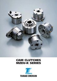
MZEU-K SERIES CAM CLUTCH<br />
B F<br />
1 7 5 6 2 3 4 8 9<br />
DF<br />
N<br />
1<br />
M<br />
O-P<br />
C<br />
A<br />
J<br />
F<br />
B<br />
10<br />
1<br />
2<br />
3<br />
4<br />
5<br />
6<br />
7<br />
8<br />
9<br />
Inner race<br />
Outer race<br />
<strong>Cam</strong><br />
Spring<br />
Bearing<br />
Side plate<br />
E1 Flange<br />
E2 Flange<br />
Socket bolt<br />
Set screw<br />
E1 Flange + E2 Flange<br />
Dimensions in mm<br />
Bore<br />
Size<br />
H7<br />
Inner<br />
Race<br />
Keyway<br />
B<br />
Model<br />
A h7 BF C<br />
DF F J M N O-P<br />
MZEU12-K E1+E2 12 4 x 1.8 42 62 85 20 72 20 1 10 5.7 3 – ø5.5 1.1<br />
MZEU15-K E1+E2 15 5 x 2.3 52 68 92 28 78 25 0.8 11.0 5.7 3 – ø5.5 1.5<br />
MZEU20-K E1+E2 20 6 x 2.8 57 75 98 34 85 30 0.8 10.5 5.7 4 – ø5.5 1.9<br />
MZEU25-K E1+E2 25 8 x 3.3 60 90 118 35 104 40 0.8 11.5 6.8 4 – ø6.6 2.9<br />
MZEU30-K E1+E2 30 8 x 3.3 68 100 128 43 114 45 1.0 11.5 6.8 6 – ø6.6 4.0<br />
MZEU35-K E1+E2 35 10 x 3.3 74 110 140 45 124 50 1.0 13.5 6.8 6 – ø6.6 5.2<br />
MZEU40-K E1+E2 40 12 x 3.3 86 125 160 53 142 55 1.3 15.5 9.0 6 – ø9.0 7.9<br />
MZEU45-K E1+E2 45 14 x 3.8 86 130 165 53 146 60 1.3 15.5 9.0 8 – ø9.0 9.3<br />
MZEU50-K E1+E2 50 14 x 3.8 94 150 185 64 166 70 1.3 14.0 9.0 8 – ø9.0 11.7<br />
MZEU55-K E1+E2 55 16 x 4.3 104 160 204 66 182 75 1.5 18.0 11.0 8 – ø11.0 15.3<br />
MZEU60-K E1+E2 60 18 x 4.4 114 170 214 78 192 80 1.5 17.0 11.0 10 – ø11.0 17.7<br />
MZEU70-K E1+E2 70 20 x 4.9 134 190 234 95 212 90 1.8 18.5 11.0 10 – ø11.0 25.5<br />
MZEU80-K E1+E2 80 22 x 5.4 144 210 254 100 232 105 1.8 21.0 11.0 10 – ø11.0 33.2<br />
MZEU90-K E1+E2 90 25 x 5.4 158 230 278 115 254 120 2.0 20.5 13.0 10 – ø14.0 38.3<br />
MZEU100-K E1+E2 100 28 x 6.4 182 270 335 120 305 140 2.0 30.0 17.5 10 – ø18.0 68.8<br />
MZEU130-K E1+E2 130 32 x 7.4 212 310 380 152 345 160 2.5 29.0 17.5 12 – ø18.0 98.2<br />
MZEU150-K E1+E2 150 36 x 8.4 246 400 485 180 445 200 2.5 32.0 21.5 12 – ø22.0 198.2<br />
Approx.<br />
Mass<br />
kg/pc<br />
Installation and Usage<br />
1. The <strong>Cam</strong> <strong>Clutch</strong> is delivered as a combination of a basic<br />
type clutch, an E1 flange and an E2 flange, each one packed<br />
and supplied as an individual part set.<br />
Each flange set comes with a complete flange kit, containing<br />
a number of bolts, a grease nipple, a locker set screw and a<br />
seal plug.<br />
2. Check the direction of rotation before assembling, then<br />
mount both flanges making use of the flange kits.<br />
3. Before mounting the sizes MZEU90-K to MZEU150-K apply<br />
the sealing adhesive, which comes along with the part sets,<br />
between body (outer race surface) and the optional part, to<br />
prevent leakage of oil during operation.<br />
4. When installing sprocket, gear, pulley or other items to the<br />
clutch, always use bolts to assemble them. Size and quantity<br />
E1<br />
are mentioned under H-L, page 17. Lengths and shape are<br />
determined by the thickness of the fitted part.<br />
5. When installing any type of optional or fitted part in the opposite<br />
way the direction of the clutch’s rotation can be<br />
changed.<br />
6. For high speed indexing applications (over 50 cycle/min) strong<br />
springs are recommended and can be supplied accordingly. Installation example 2<br />
E2<br />
18 Innovation in Motion


