Grob Astir CS 102 Manual - Pittsburgh Soaring Club
Grob Astir CS 102 Manual - Pittsburgh Soaring Club
Grob Astir CS 102 Manual - Pittsburgh Soaring Club

Create successful ePaper yourself
Turn your PDF publications into a flip-book with our unique Google optimized e-Paper software.
FLIGHT MANUAL G<strong>102</strong><br />
The <strong>Manual</strong> belongs to ASTIR <strong>CS</strong><br />
Registration Number:<br />
Serial Number:<br />
Manufactured by: Burkhart <strong>Grob</strong> Flugzeugbau<br />
86874 Tussenhausen - Mattsies<br />
Flugplatz Mindelheim - Mattsies<br />
Telephone: 08268-998-0<br />
e-mail: productsupport@grob-aerospace.de<br />
Germany<br />
Owner:<br />
Published: August 1975<br />
This manual should always be kept on board the glider
FLIGHT MANUAL ASTIR <strong>CS</strong><br />
2<br />
List of effective pages<br />
Chapter Page Date Reference<br />
Flight <strong>Manual</strong><br />
Cover Page<br />
2<br />
3<br />
4<br />
5<br />
6<br />
7<br />
8<br />
9<br />
10<br />
11<br />
12<br />
13<br />
14<br />
15<br />
16<br />
17<br />
18<br />
19<br />
20<br />
21<br />
22<br />
23<br />
28.11.2005<br />
28.11.2005<br />
28.11.2005<br />
28.11.2005<br />
28.11.2005<br />
28.11.2005<br />
28.11.2005<br />
28.11.2005<br />
28.11.2005<br />
28.11.2005<br />
28.11.2005<br />
28.11.2005<br />
28.11.2005<br />
28.11.2005<br />
28.11.2005<br />
28.11.2005<br />
28.11.2005<br />
28.11.2005<br />
28.11.2005<br />
28.11.2005<br />
28.11.2005<br />
28.11.2005<br />
28.11.2005<br />
Rev. 9 28. Nov. 2005
FLIGHT MANUAL ASTIR <strong>CS</strong><br />
3<br />
Contents<br />
Contents<br />
page<br />
List of effective pages........................................................................... 2<br />
Contents................................................................................................ 3<br />
Addenda................................................................................................ 4<br />
Flying Limitations.................................................................................. 5<br />
Record of weight alterations and weighing........................................... 7<br />
Placards to be displayed in the cockpit ................................................ 9<br />
Notes on Flying the Glider.................................................................. 13<br />
Emergency Procedures...................................................................... 16<br />
Minimum equipment ........................................................................... 18<br />
Weight and center of gravity positions ............................................... 18<br />
Measurements.................................................................................... 18<br />
Weights and moments of the control surfaces ................................... 22<br />
Assembly ............................................................................................ 22<br />
Checks to be made after assembly .................................................... 24<br />
Pre-Launch checks............................................................................. 24<br />
Rev. 9 28. Nov. 2005
FLIGHT MANUAL ASTIR <strong>CS</strong><br />
5<br />
Flying Limitations<br />
Airspeed Limits (I.A.S.) km/h mph kts<br />
Never exceed (V NE ) ..............................250 ...........155..........135<br />
in rough air (V B )................................... 250 .......... 155......... 135<br />
Maneuvering (V A ) ...............................170 .......... 105 ...........92<br />
On aero tow (V T ) .................................... 170............105 ............92<br />
On winch tow (V w ) ...................................120 ............. 74.............64<br />
Airbrakes ................................................. 250............ 155...........135<br />
Gear extended .......................................250 ........... 155..........135<br />
A.S.I. Colour Code<br />
33 - 92 kts .............................. Green Border - 60-170 km/h<br />
92 - 135 kts ............................ Yellow Border - 170-250 km/h<br />
At 135 kts ..........................................Red Strip - bei 250 km/h<br />
Weights lbs kp<br />
Empty Weight.................................................circa 560..........255<br />
Maximum permitted weight<br />
without water-ballast ...........................................836 ........ 380<br />
with water-ballast ............................................... 990 .........450<br />
Maximum permitted weight<br />
of non-supporting ports ........................................... 528 ..........240<br />
Weak Link on Winch cable<br />
Maximum Load ....................................................... 1100 ..........500<br />
Cloud Flying and simple Aerobatics<br />
Permitted if water-ballast is not being carried: See pages 12 - 14<br />
Rev. 9 28. Nov. 2005
FLIGHT MANUAL ASTIR <strong>CS</strong><br />
6<br />
Classification Group<br />
Standard Class (German N)<br />
Centre of Gravity positions<br />
Leveling means<br />
Datum Line (D, L.)<br />
Serial-No. 1002 – 1437:<br />
Maximum forward position of C. of G.<br />
Maximum rearward position<br />
Serial–No. 1438 – 1536:<br />
Maximum forward position of C. of G.<br />
Maximum rearward position<br />
with a 1000:40 Incidence Board<br />
set up horizontal on the top of<br />
the rear fuselage.<br />
Front edge) of wing at root<br />
250 mm behind D. L. (9.84 in)<br />
425 mm behind D. L. (16.73 in)<br />
310 mm behind D. L. (12,20 in)<br />
480 mm behind D. L. (18,90 in)<br />
Loading Limitations ASTIR <strong>CS</strong><br />
Empty weight of glider and maximum cockpit load, see page 7.<br />
Minimum cockpit load: 154 lbs (70 kp)<br />
The permissible all up weight must NEVER be exceeded.<br />
Maximum all up weight<br />
without water-ballast 836 lbs (380 kp)<br />
with water-ballast 990 lbs (450 kp)<br />
The weight of water-ballast is dependent on the cockpit weight (Pilot<br />
with parachute and luggage). See page 7.<br />
Weight deficiencies should be corrected by securing or removing some<br />
ballast in the seat.<br />
The C. of G. of the pilot with a parachute on lies 475 mm in front of<br />
the Datum Line.<br />
Rev. 9 28. Nov. 2005
FLIGHT MANUAL ASTIR <strong>CS</strong><br />
7<br />
Record of weight alterations and weighing<br />
ASTIR <strong>CS</strong><br />
Works Number:<br />
Date of weight<br />
alteration:<br />
Weighing by<br />
List of<br />
accessories<br />
(Date):<br />
Empty Weight<br />
(lbs):<br />
Empty Weight<br />
C. of G.<br />
position<br />
behind D.L.<br />
(mm)<br />
Maximum<br />
Cockpit<br />
Weight (lbs)<br />
Rev. 9 28. Nov. 2005
FLIGHT MANUAL ASTIR <strong>CS</strong><br />
8<br />
Rev. 9 28. Nov. 2005
FLIGHT MANUAL ASTIR <strong>CS</strong><br />
9<br />
Placards to be displayed in the cockpit<br />
Maximum weight kp lbs<br />
without water ballast: 380 836<br />
with water ballast: 450 990<br />
Airspeed limits km/h rn.p.h. knots<br />
Never exceed 250 155 135<br />
in rough air 250 155 135<br />
Manoeuvring 170 105 92<br />
On aero tow 170 105 92<br />
On winch tow 120 74 64<br />
Airbrakes 250 155 135<br />
Gear extended 250 155 135<br />
Payload (pilot and parachute)<br />
The maximum weight must not be exceeded.<br />
Minimum payload: 70 kp, 154 lbs.<br />
Less weight must be compensated with<br />
ballast in the seat.<br />
Placard to be displayed near undercarriage<br />
Weak links for towing<br />
500 kp, 1100 lbs. max.<br />
Tire: 2,5 bar, 36 psi<br />
Rev. 9 28. Nov. 2005
FLIGHT MANUAL ASTIR <strong>CS</strong><br />
10<br />
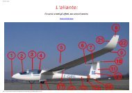
Ballast Weight<br />
Pilot Weight<br />
Incl. Parachute<br />
Quantity<br />
(Total)<br />
kg<br />
lbs<br />
55 120 6<br />
60 130 4<br />
65 145 2<br />
70 - 100 155 - 220 0<br />
Cover of the container has to be closed tight.<br />
Ballast weight<br />
red<br />
Rev. 9 28. Nov. 2005
FLIGHT MANUAL ASTIR <strong>CS</strong><br />
11<br />
DOWN Under-carriage UP<br />
Handle moves in<br />
Slot on right of<br />
cockpit<br />
Trimmer<br />
On left of cockpit.<br />
GREEN lever<br />
Air-brakes<br />
On the left-hand<br />
Side of the cockpit<br />
BLUE handle<br />
Water-ballast<br />
Jettison<br />
On the right of the<br />
Cockpit.<br />
WHITE lever<br />
Canopy<br />
Round RED knobs.<br />
Left of canopy-frame<br />
OPEN.<br />
Right of canopy-<br />
Frame JETTISON<br />
Pedal<br />
Adjustment<br />
Small BLACK<br />
knob<br />
On the top of the<br />
Instrument panel<br />
(right hand)<br />
Air-vent<br />
Small BLACK<br />
knob<br />
On the top of the<br />
instrument panel.<br />
(left hand)<br />
Cable Release<br />
In front of the stick<br />
on the left.<br />
YELLOW knob<br />
Rev. 9 28. Nov. 2005
FLIGHT MANUAL ASTIR <strong>CS</strong><br />
12<br />
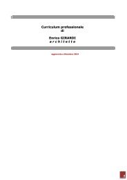
Graph of True v. Indicated Airspeed, showing the effect of Position<br />
Errors.<br />
When the A.S.I. is connected to the following pressure sources:<br />
A.S.I. - Pitot head in tail fin static vents side of the fuselage before the wing root.<br />
Rev. 9 28. Nov. 2005
FLIGHT MANUAL ASTIR <strong>CS</strong><br />
13<br />
Notes on Flying the Glider<br />
Winch/Auto-tow-Launch<br />
Maximum permitted launch speed:<br />
64 kts<br />
The glider has a belly-hook in the undercarriage well in front of the wheel. A cable<br />
launch presents no difficulties with any C. of G. positions or weight configurations. The<br />
glider has no tendency to balloon and is very stable on the launch. Up to a height of<br />
300ft the nose should be held down if the launch is fast.<br />
Aero tow<br />
Maximum permitted towing speed:<br />
92 kts<br />
The gliders C. of G. position allows the aero tow to be carried out using either the nose<br />
— or belly-hook. During the whole of the time on tow, the glider can be easily controlled<br />
with rudder and aileron, full movements of which can be used if necessary. Even in<br />
strong cross-winds the glider shows no tendency to wander around. At 32 kts the glider<br />
can be lifted off: with 37 — 40 kts indicated, the glider climbs on its own. The<br />
undercarriage can be retracted whilst still on tow. The yellow release knob is positioned<br />
on the left in front of the stick, and should be pulled fully back when releasing the towrope.<br />
Weak Link in tow-cable<br />
Maximum load<br />
1100 lbs<br />
Rudder-pedal Adjustment<br />
To adjust the rudder pedals, push lightly forward on them with the heels and disconnect<br />
the locking device by pulling the handle on the instrument panel. The pedals move<br />
towards the pilot by themselves: to adjust them forward you have to push them against<br />
the pressure of the springs with your heels. The pedals will lock themselves in the<br />
position required when the handle is released.<br />
Canopy<br />
The single-piece perspex canopy has a clear-vision panel and ventilation port, and is<br />
fitted on hinges. The handle for opening it is located on the left-hand side of the canopy<br />
surround: that for jettisoning is on the right-hand fuselage side. To jettison the canopy,<br />
pull both handles back and push it up and away with the left hand.<br />
Rev. 9 28. Nov. 2005
FLIGHT MANUAL ASTIR <strong>CS</strong><br />
14<br />
Retractable Undercarriage<br />
The undercarriage control lever is located on the right of the cockpit. When retracted or<br />
lowered, the wheel should be locked in place by pushing the control lever in towards<br />
the fuselage side.<br />
Air-brakes<br />
The lever for the air-brakes is situated on the left-hand side of the cockpit. Before<br />
beginning a launch, check that the air-brakes are closed and locked. One should avoid<br />
trying to land with full brake out, since the effectiveness of the brakes means that the<br />
glider is descending fast.<br />
Wheel brake<br />
The lever for the wheel brake is located on the stick.<br />
Trim<br />
The built-in trimmer can be progressively adjusted. The control lever for it is positioned<br />
on the left-hand side of the cockpit behind the airbrake lever. Trim range from 32 kts —<br />
97 kts.<br />
Flight with water-ballast<br />
The glider has the same all up weight as a standard 2 seat glider, when loaded with<br />
water-ballast and a full cockpit load. The slow flight and stalling characteristics of the<br />
fully loaded glider are a little different from one flown without water-ballast. The stalling<br />
speed will be increased to 38 kts. Also larger control movements will be necessary.<br />
The glider will spin cleanly but will recover immediately spin recovery action is taken.<br />
The pilot is advised to have extra height when slow flying or approaching to land while<br />
carrying water-ballast.<br />
Use of Water-ballast<br />
The water-ballast tanks are situated in the front part of the wings, from the root<br />
outwards. Each wing can hold 50 litres. The tanks are filled through an opening in the<br />
top surface of the wing. This is covered by a plug, which can be removed by screwing in<br />
a bolt. The water is drained off through an opening in the underside of the fuselage<br />
behind the wheel-box. To open the valves of the tanks, the control lever on the righthand<br />
side of the cockpit should be pulled backwards. It takes about 3 minutes for the<br />
tanks to empty themselves.<br />
Rev. 9 28. Nov. 2005
FLIGHT MANUAL ASTIR <strong>CS</strong><br />
15<br />
Air from the tanks escapes through the overflow pipe that runs down to a point an the<br />
underside of the wing near the root. When flying with water-ballast the connecting-tape<br />
that covers the gap between fuselage and wings, should be folded back on the<br />
underside in the region of the spar, so that any excess water which may appear runs out<br />
rather than down into the fuselage.<br />
During long flights at an air temperature of 0 ° C (32 ° F) the water-ballast must be<br />
jettisoned because there is danger of collapse of the ballast tanks. When a field landing is<br />
to be made the water-ballast must be jettisoned.<br />
The glider must not be parked over-night with water-ballast on board. If the glider has to<br />
be towed for a long way on the ground with water-ballast on board, the tanks should be<br />
emptied.<br />
When de-rigging the water-ballast tanks will empty themselves through the wing root<br />
connecting pipes.<br />
Stalling Characteristics<br />
Warning of the stall occurs at a speed of 32-35 kts (depending on wing loading), when the<br />
top of the tail unit begins to shudder. If the stick is pulled back even further, the glider<br />
"mushes" but, remains controllable, it being possible to make turns up to an angle of<br />
bank of 20' without the wing dropping away. If the stick is released the glider returns<br />
immediately to the normal flying attitude. If the stick is pulled back quickly, the nose will<br />
drop away but any tendency for a wing to fall can be controlled by the rudder.<br />
Aerobatics<br />
Permitted maneuvers and speeds at which they should be initiated:<br />
Loop ..........................................................................................................................92 kts<br />
Chandelle...................................................................................................................92 kts<br />
Steep turn................................................................................................................. 65 kts<br />
Lazy eight ..................................................................................................................65 kts<br />
Spins:<br />
From the fully stalled position, put on full aileron and rudder (crossed). Keep the stick<br />
back. To stop the spin centralize or release one of the controls. Height lost per rotation<br />
is approximately 220 ft. The speed reached when leveling out is about 86 kts.<br />
Maximal positive g loading + 5,3.<br />
Manoeuvres that involve negative g loads are prohibited.<br />
Unorthodox manoeuvres are likewise prohibited<br />
Rev. 9 28. Nov. 2005
FLIGHT MANUAL ASTIR <strong>CS</strong><br />
16<br />
Spinning<br />
With the Center of Gravity between 415 mm and 480 mm behind the Datum Line, it is<br />
possible to put the glider into a spin from the stalled position. To do so the stick has to<br />
be pulled fully back, and the rudder and aileron controls be fully crossed. The nose will<br />
then drop in the direction in which rudder is being applied, and with a rearward C of G.<br />
position the glider will rotate in a slow, flat spin.<br />
Recovery from the spin can be effected in any way you choose. With almost all C. of G.<br />
positions and wing loadings all that is required is for one of the controls to be released<br />
or returned to its normal position. The quickest recovery (without overstressing the<br />
glider) can be brought about by centralizing all of the controls. The height lost in<br />
returning to the normal flying position after a single-rotation spin, is about 220 ft,<br />
If the glider fails to stop spinning immediately the controls have been centralized, then<br />
the standard method of spin recovery should be employed at once:<br />
1. Full opposite rudder<br />
2. Pause<br />
3. Stick steadily forward<br />
4. When spin stops, centralize controls and resume normal flight<br />
Speed Flying<br />
In speed flying it is quite possible to exceed the maximum permitted speed. At very high<br />
air speeds, care should be taken to use only small control movements so as not to<br />
overstress the glider:<br />
Emergency Procedures<br />
Escape Procedure<br />
In the event of a bail out, the following procedure should be followed:<br />
1. Pull both red knobs back on right and left of canopy surround and with left hand<br />
push canopy upwards and backwards.<br />
2. Unbuckle seat harness.<br />
3. EXIT over left or right side<br />
4. Wait only 1 — 3 seconds before pulling the rip cord<br />
Rev. 9 28. Nov. 2005
FLIGHT MANUAL ASTIR <strong>CS</strong><br />
17<br />
Flying at High Speed<br />
Within the permitted speed range the glider has no tendency towards high speed flutter.<br />
The controls need only be used at 1/3 of their full movement at 93 kts. The air brakes are<br />
speed limiting and with them open the glider will only reach about 108 kts even in a 45°<br />
dive.<br />
Approach and Landing<br />
The glider can be brought in quite normally at an approach speed of 50 kts. The airbrakes<br />
allow a steep approach to be made quite easily. As the action of the brakes makes<br />
the glider slightly nose-heavy, the machine will itself maintain the airspeed it is set at<br />
when the brakes are opened. The sideslip is quite controllable and, if needed, this<br />
manoeuvre can be used to help land the glider.<br />
ATTENTION:<br />
Landing circuit check:<br />
Height 500 ft.<br />
Airspeed 50 kts.<br />
WHEEL DOWN AND LOCKED<br />
Flying in rain<br />
A thin layer of water or ice on the wings leads to no deterioration in the flying<br />
characteristics of the glider. With more substantial deposits the stalling speed is<br />
increased by about 3 kts, although the way the glider takes off and touches down<br />
remains the same. Increase the normal flying speed accordingly.<br />
Cloud-flying<br />
The minimum set of Instruments required before cloud flying should be attempted is:<br />
A.S.I., Altimeter, Compass, Turn and Slip Indicator and Radio<br />
The A.S.I. must have the maximum permitted speed marked on it, i. e. red section.<br />
In order to avoid exceeding the maximum permitted speed, the airbrakes should be<br />
opened in good time (i. e. at about 86 kts.)<br />
Warning: Cloud flying and aerobatics should only be carried out by pilots who possess<br />
the appropriate authorization. The statutory regulations must be adhered to.<br />
Rev. 9 28. Nov. 2005
FLIGHT MANUAL ASTIR <strong>CS</strong><br />
18<br />
Minimum equipment<br />
1. 160kts. A.S.I<br />
2. Altimeter<br />
3. Vertical speed indicator<br />
4. Four piece safety harness<br />
5. Weighted seat cushion at least 2 3/4", thick, or parachute<br />
6. Loading limitations chart<br />
7. Flying limitations placard<br />
8. Flight manual<br />
Weight and center of gravity positions<br />
If new Instruments are added and other changes in the weight of the glider are<br />
made, the empty weight C. of G. position should be checked. If the limits of the<br />
empty weight C. of G. positions and the Loading Limitations Chart are adhered to,<br />
then the C. of G. of the loaded glider will lie within the permitted range.<br />
Serial-No. 1001- 1437 Serial-No. 1438 - 1536<br />
Empty C. of G. position Empty C. of G. position<br />
Weight (lbs) (mm behind Weight (lbs) (mm behind<br />
Datum Line)<br />
Datum Line)<br />
506 606 — 693 539 696 — 753<br />
517 598 — 693 550 688 — 747<br />
528 591 — 637 561 681 — 742<br />
539 534 — 682 572 673 — 737<br />
550 577 — 677 583 652 — 732<br />
561 557 — 672 594 631 — 728<br />
572 537 — 667 605 611 — 723<br />
583 518 — 662 616 591 — 719<br />
594 499 — 658 527 573 — 715<br />
605 481 — 654<br />
Measurements<br />
Position of the glider whilst taking all measurements:<br />
with a 1000:40 Incidence Board set up horizontal on the top of the rear fuselage.<br />
Rev. 9 28. Nov. 2005
FLIGHT MANUAL ASTIR <strong>CS</strong><br />
19<br />
ASTIR <strong>CS</strong> Serial No. 1438 – 1536<br />
Rev. 9 28. Nov. 2005
FLIGHT MANUAL ASTIR <strong>CS</strong><br />
20<br />
Performance 350 kp 450 kp<br />
Best Glide Angle 37,3 - 95 38 – 105km/h<br />
Minimum Sink (m/sec) 0,6 -75 0,7 – 85 km/h<br />
Circling speed 80 – 85 90 – 95 km/h<br />
Rev. 9 28. Nov. 2005
FLIGHT MANUAL ASTIR <strong>CS</strong><br />
21<br />
Weights<br />
Datum Line: Front edge of the wing at the root.<br />
Leveling means: With a 1000:40 Incidence Board set up horizontal on the top of<br />
the rear fuselage.<br />
Weight on main-wheel G 1 = lbs<br />
Weight on tail-skid G 2 = lbs<br />
Empty Weight G L = G 1 + G 2 = lbs<br />
Displacement of main-wheel a = mm<br />
Displacement of tail-skid b = mm<br />
Empty Weight C. of G.<br />
G 2 x b<br />
X = + a = + = mm behind Datum Line<br />
G L<br />
Maximum Load G = 836 – G L = lbs<br />
The measurements of determine the empty weight, the empty weight C. of G. and the<br />
loading limitations should always be taken with the glider empty of water ballast<br />
Rev. 9 28. Nov. 2005
FLIGHT MANUAL ASTIR <strong>CS</strong><br />
22<br />
Weights and moments of the control surfaces<br />
After painting, partial painting or repairs the weights and moments and must not exceed.<br />
Procedure and limits see: Maintenance <strong>Manual</strong> ASTIR <strong>CS</strong> and SB 306-34, latest<br />
revision.<br />
Assembly<br />
It is possible to rig the glider with three people.<br />
1. Wings:<br />
Open the 4 main wing fittings in the fuselage. Unlock the air-brakes on the wings. Guide<br />
the right wing into the fuselage. The safety catches on the fuselage sockets will be<br />
released, and on gently moving the wing to and fro will be heard to snap into place.<br />
Next guide the left wing into the fuselage. Move the wing tips up and down so that the<br />
pin on each spar stub is located in the appropriate hole in the opposite wing root. Next the<br />
catches on the left-hand fuselage sockets should be released, and by moving the wing<br />
back-wards and forwards they too can be made to snap into place. To ensure that the<br />
wing-fuselage joint is safely secured, turn the socket catches towards the bayonets<br />
until they drop into place.<br />
Checks<br />
The red circles on the fuselage sides must be covered by the rotated sockets.<br />
2. Aileron and air - brake-connections:<br />
The short connecting rods in the fuselage are fitted with quick-action locks which must<br />
be coupled up to the knobs of the push-rods that move inside the wings.<br />
To fasten the quick action locks, a special tool is provided which guarantees that the knobs<br />
are correctly located in the locks.<br />
After rigging, the connecting rods should be examined to check that pins are properly<br />
inserted, and project some mm out of the locks.<br />
After coupling the quick action locks, check that the ball can not be extracted, by twisting<br />
the lock back and forth. Do this gently with not more than 10 lbs pull. Check all control<br />
connecting rods and locks in a methodical order.<br />
Rev. 9 28. Nov. 2005
FLIGHT MANUAL ASTIR <strong>CS</strong><br />
23<br />
After rigging the following check must be carried out to check the connections are<br />
secure:<br />
open<br />
closed<br />
locked<br />
Max. Position<br />
After connecting the quick lock couplings make a visual check that the collar is<br />
extended forward over the bearing far enough for the safety pin to engage.<br />
Rev. 9 28. Nov. 2005
FLIGHT MANUAL ASTIR <strong>CS</strong><br />
24<br />
3. Tail plane<br />
The tail plane can be fixed in place by a single person. Stand in front of the fin. Rest<br />
the elevator on the rudder and point the tailplane upwards at an angle of about 45° with<br />
the fin. Next couple the elevator push-road to the knob on the elevator by means of the<br />
quick-action lock. Now drop the tailplane down so that the two retaining pins on the<br />
fuselage disappear up into the cavity in the tailplane. One can now let go of the<br />
tailplane.<br />
To continue with the rigging push the front of the tailplane down. This will activate the<br />
locking bolt and cause the metal pin that projects out of the front of the fin to move<br />
down its slot. When the front of the tailplane has reached its lowest position against the<br />
pressure of the locking mechanism, push the whole unit back with both and into the two<br />
fuselage bolts. The unit is then locked in place when the metal pin in the front of the fin<br />
springs upwards and covers the long narrow slot.<br />
Checks to be made after assembly<br />
1 Check that the 4 main wing fittings are locked.<br />
2 Check that aileron and brake quick-action locks are properly located on the knobs.<br />
3 Ensure that the tow hook is functioning correctly.<br />
4 Test the operation of the wheel brake and the pressure of the air in the tire.<br />
5 Check that the tailplane is securely seated and that the elevator push-rod is<br />
connected.<br />
8 Rudder movement.<br />
Pre-Launch checks<br />
1 Do all the controls move freely?<br />
2 Are the air-brakes locked?<br />
3 Is the undercarriage control lever in the most forward position and is it pushed in<br />
flush with the fuselage-wall?<br />
4 Is the trimmer set at neutral?<br />
5 Is the canopy locked?<br />
6 Are the parachute and seat straps drawn in tight and secured?<br />
7 Is the altimeter set to ZERO or the height of the airfield?<br />
8 Is the radio turned on and set to the frequency being used by the airfield control?<br />
Rev. 9 28. Nov. 2005
FLIGHT MANUAL ASTIR <strong>CS</strong><br />
25<br />
Inspection of the airbrake locking lever<br />
At the daily check the right and left hand airbrake locking levers have to be checked<br />
through the inspection openings in the wing underside. The lever are made of aluminum<br />
casting and have a facilitating hole. The following instruction has to be carried out:<br />
Inspection of the airbrake locking levers for cracks in one of the 3 legs. For a better<br />
inspection the Plexiglas pane can be removed for easier access. The use of a<br />
magnifying glass is recommended.<br />
If cracks are found, the exchange of the locking levers left and right hand No. <strong>102</strong>-<br />
4123/4124 of aluminum casting for such of aluminum sheet (see TM 306-26) is required.<br />
If the aluminum sheet's are installed, the daily check is not longer applicable.<br />
Rev. 9 28. Nov. 2005
MAINTENANCE MANUAL G<strong>102</strong><br />
The <strong>Manual</strong> belongs to ASTIR <strong>CS</strong><br />
Registration Number:<br />
Serial Number:<br />
Manufactured by: Burkhart <strong>Grob</strong> Flugzeugbau<br />
86874 Tussenhausen - Mattsies<br />
Flugplatz Mindelheim - Mattsies<br />
Telephone: 08268-998-0<br />
e-mail: productsupport@grob-aerospace.de<br />
Germany<br />
Owner:<br />
Published: August 1975
MAINTENANCE MANUAL ASTIR <strong>CS</strong><br />
2<br />
List of effective pages<br />
Chapter Page Date Reference<br />
Maintenance<br />
<strong>Manual</strong><br />
Cover Page<br />
2<br />
3<br />
4<br />
5<br />
6<br />
7<br />
8<br />
9<br />
10<br />
28.11.2005<br />
28.11.2005<br />
28.11.2005<br />
28.11.2005<br />
28.11.2005<br />
28.11.2005<br />
28.11.2005<br />
28.11.2005<br />
28.11.2005<br />
28.11.2005<br />
MSB 306-38/1<br />
Rev. 9 28. Nov. 2005
MAINTENANCE MANUAL ASTIR <strong>CS</strong><br />
3<br />
Contents<br />
Contents<br />
page<br />
List of effective pages..........................................................................................2<br />
Contents ..............................................................................................................3<br />
Addenda ..............................................................................................................4<br />
Maintenance ........................................................................................................5<br />
Annual Inspection................................................................................................7<br />
Life limited parts...................................................................................................8<br />
Weights and moments of the control surfaces ...................................................9<br />
Inspection Procedures for Increase of Service Time........................................10<br />
Rev. 9 28. Nov. 2005
MAINTENANCE MANUAL ASTIR <strong>CS</strong><br />
5<br />
Maintenance<br />
The greatest care should be taken in maintaining the fiber glass surface of the glider.<br />
Luke warm water should be used to wash off dust, grease, dead flies and other dirty<br />
marks. More resistant dirt should be removed by using a mild cleaning agent. Only<br />
special silicon-free preparations should be used in maintaining the painted surfaces.<br />
Cracks should be carefully filled.<br />
Although very resistant against moisture, the glider should be protected as much as<br />
possible against rain and dampness. Water that has penetrated, should be dealt with<br />
by storing the glider in a dry place, frequently turning over the dismantled parts.<br />
The most effective way to clean the canopy is to use a special perspex cleaner, but if<br />
necessary, lukewarm water can be used. A soft, clean cloth or chamois-leather should<br />
be employed to wipe the canopy down. Never rub perspex with anything dry.<br />
The safety harness should be regularly checked for mildew and general wear and tear.<br />
The metal parts of the harness should be frequently checked for rust.<br />
Because of its position in the wheel cavity the tow-hook is susceptible to contamination<br />
from dirt. Therefore it must be inspected frequently for damage, also regularly clean and<br />
b grease. When the seat-well is removed the hook can easily be taken out. Remove the<br />
connecting wire from the lever and take out two retaining screws. For reconditioning the<br />
tow hook should be sent with the record card to the tow hook manufacturer, Tost.<br />
The main wheel tire pressure should be kept at 2,5 atmospheres (36 psi).<br />
A tail wheel can also be installed instead of the skid<br />
The wheel brake is of the drum type. If required the point at which the brake begins to<br />
drag can be adjusted. The adjustment is carried out by moving the Bowden cable at the<br />
drum end.<br />
When the main wheel is removed for the purpose of cleaning, greasing or changing<br />
the tire, the Bowden cable should be disconnected from the brake-lever. Screw the M 6<br />
threaded special tool onto one side of the axle and take out the screws and the spindle.<br />
Remove the screws that hold the brake-lever in place. Take the wheel out by pulling it<br />
downwards. Clean all the parts and grease before re-assembly.<br />
Before assembling the glider the pins and sockets at the joints between wings and<br />
fuselage, and tailplane and fuselage, should be cleaned and greased.<br />
If repairs are carried out on the glider which are more extensive than normal<br />
maintenance work, the manufacturers should be contacted.<br />
Rev. 9 28. Nov. 2005
MAINTENANCE MANUAL ASTIR <strong>CS</strong><br />
6<br />
It is absolutely essential to ensure that if the glider is re-painted all surfaces which<br />
are directly exposed to the sun should be painted WHITE.<br />
When any repairs are done or a fresh coat of paint added the position of the<br />
empty weight C. of G. must be re-checked.<br />
Maintenance on Hotellier quick-locks must be conducted during each annual<br />
inspection or 500 hours which ever occurs first. They are installed at the controlconnections<br />
of aileron and airbrakes at the wing-fuselage joint and at the elevator<br />
connection to the pushrod.<br />
The diameter of the swivel has to be measured at different points by a<br />
micrometer with no differences in excess of 0,1 mm (0,004 in.) that means the<br />
swivel must still be spherical. If there are large differences the swivels and<br />
appropriate joints must be replaced.<br />
Swivels and joints should be greased prior to each rigging.<br />
The use of additional safety-pins guided through the holes of the wedge-type slides<br />
increases safety, (Safety-pins No. 500 307.71 from A. Wurth, Industrieservice, D –<br />
90431 Nuernberg, Germany or from GROB- Werke)<br />
Rev. 9 28. Nov. 2005
MAINTENANCE MANUAL ASTIR <strong>CS</strong><br />
7<br />
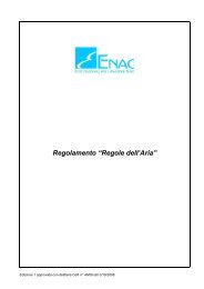
Annual Inspection<br />
During each annual inspection check front and rear attachment for noticeable play<br />
before de-rigging the horizontal stabilizer. Therefore move the stabilizer at the tips<br />
carefully to all directions.<br />
• If play is noticed in the front attachment the spherical bolt must be replaced (see<br />
figure 1). Determine the ball diameter. When ordering advise the measured diameter<br />
"D" + 0.1 mm. Also advise gap width “S” as measured.<br />
• Remove spherical bolt from elevator. Check bolt for cracks.<br />
• Upon re-installation apply correct torque. (20 Nm, tolerance +4 / -2). (NOTE: See<br />
also MSB 306-38).<br />
Torque with 13 Nm<br />
Figure 2<br />
• if play is noticed in the rear attachment the retaining pins <strong>102</strong>-2142.46 must be<br />
replaced as follows: (refer to figure 2):<br />
• remove horizontal stabilizer.<br />
• loosen nut M8, hold bolt using a screwdriver.<br />
• during removal of the bolts pay attention that the large washers remain on the<br />
aluminum plate.<br />
Rev. 9 28. Nov. 2005
MAINTENANCE MANUAL ASTIR <strong>CS</strong><br />
8<br />
• install new spherical bolts and pay attention that they are properly positioned<br />
in the large washers.<br />
• tighten nut using a torque wrench with 13Nm.<br />
• install horizontal stabilizer and connect control rods.<br />
In case play is still noticeable after replacement of the bolts, the bearings in the<br />
stabilizer spar web must be replaced. This replacement must be done only by an<br />
approved aviation workshop.<br />
Corresponding instructions may be ordered from GROB.<br />
Life limited parts<br />
Mandatory Service Bulletin MSB 306-38 introduced the annual inspection and – if<br />
required – the exchange of the spherical bolt <strong>102</strong>-3500.21.<br />
Mandatory Service Bulletin MSB 306-38/1 require all spherical bolts <strong>102</strong>-3500.21 and<br />
collar bolts <strong>102</strong>-2142.46 be exchanged not later than June 30 th 2006, unless already<br />
exchanged within the scope of MSB 306-38. Additionally every 10 years / 1000<br />
landings, whichever comes first, spherical bolt <strong>102</strong>-3500.21 and collar bolts <strong>102</strong>-<br />
2142.46 need to be replaced with new bolts.<br />
The change is to be documented in the aircraft history record and life-limited-parts list.<br />
Rev. 9 28. Nov. 2005
MAINTENANCE MANUAL ASTIR <strong>CS</strong><br />
9<br />
Weights and moments of the control surfaces<br />
The weights and the moments of the control surfaces must not exceed the following<br />
values:<br />
ASTIR <strong>CS</strong> (Serial No. 1002 - 1536)<br />
Elevator .................................... 10,00 – 15,00 kgcm ...................... 2,40 – 3,25 kg<br />
Rudder...................................... 13,65 kgcm ± 10% ........................ 3,20 kg ± 10%<br />
Aileron ...................................... 16,00 kgcm ± 12% ........................ 4,10 kg ± 12%<br />
The moments must be measured with the control surfaces removed. To determine the<br />
moment M = P x r the surface should be mounted at the hinge line with the minimum<br />
friction possible. The force P can be measured, for example, using a letter scale. If<br />
these values are exceeded the mass balance should be increased. Before carrying out<br />
repairs which for example involve charging the mass balance on a surface the<br />
manufacturer or his repair agent should be consulted.<br />
Rev. 9 28. Nov. 2005
MAINTENANCE MANUAL ASTIR <strong>CS</strong><br />
10<br />
Inspection Procedures for Increase of Service Time<br />
1. General<br />
The results of fatigue tests of wing spar sections have demonstrated recently that the<br />
service time of GRP gliders and motor gliders may be extended to 6000 hours, if for<br />
each individual glider (in addition to the obligatory annual inspections) the airworthiness<br />
is demonstrated according to a special multi-step inspection program particularly with<br />
regard to the service life.<br />
2. Time limits<br />
When the glider has reached a service time of 3000 hours, an inspection must be done<br />
in accordance with the inspection program mentioned under point 3. If the results of<br />
this inspection are positive or if any defects found have been duly repaired, the service<br />
time of the glider is extended by another 3000 hours to a total of 6000 hours (first<br />
step).<br />
The above inspection program must be repeated when the glider has reached a service<br />
time of 6000 hours. If the results of this inspection are positive or if any defects found<br />
have been duly repaired, the service time of the glider is extended to 7000 hours<br />
(second step).<br />
When the glider has reached a service time of 7000 hours, the above inspection<br />
program again must be repeated. If the results of the inspection are still positive or if any<br />
defects found have been duly repaired, the service time may be extended to a total of<br />
8000 hours (third step).<br />
The gradual extension of service life will be performed by steps of 1000 flight hours up<br />
to maximum 12 000 flight hours at this time (4 th – 7 th stage).<br />
Additionally at 9500, 10500, 11500 operating hours, inspection of the wing connection<br />
bolts and main spars spigots must be performed accordance to Service Bulletin TM<br />
306-30, latest edition, action 7.<br />
3. Inspection Program<br />
In each case the latest issue of the inspection program which will be updated<br />
according to incoming inspection results, has to be ordered from the manufacturer.<br />
Rev. 9 28. Nov. 2005
MAINTENANCE MANUAL ASTIR <strong>CS</strong><br />
11<br />
4. Inspections<br />
The inspection must only be done by the manufacturer or by a licensed repair station<br />
or inspector.<br />
5. Inspection results<br />
The results of the inspections have to be recorded in an inspection test report wherein<br />
comments are required for each inspection instruction. If the inspections are done<br />
outside the manufacturer's facilities, a copy of the records must be sent to the<br />
manufacturer for his evaluation and information<br />
6. Annual Inspection<br />
The annual inspection is not affected by this inspection program.<br />
Rev. 9 28. Nov. 2005
REPAIR INSTRUCTION G<strong>102</strong><br />
The <strong>Manual</strong> belongs to ASTIR <strong>CS</strong><br />
Registration Number:<br />
Serial Number:<br />
Manufactured by: Burkhart <strong>Grob</strong> Flugzeugbau<br />
86874 Tussenhausen - Mattsies<br />
Flugplatz Mindelheim - Mattsies<br />
Telephone: 08268-998-0<br />
e-mail: productsupport@grob-aerospace.de<br />
Germany<br />
Owner:<br />
Published: August 1975
REPAIR INSTRUCTION ASTIR <strong>CS</strong><br />
2<br />
List of effective Pages<br />
Chapter Page Date Reference<br />
Repair<br />
Instruction<br />
Cover Page<br />
2<br />
3<br />
4<br />
5<br />
6<br />
7<br />
8<br />
9<br />
10<br />
11<br />
12<br />
28.11.2005<br />
28.11.2005<br />
28.11.2005<br />
28.11.2005<br />
28.11.2005<br />
28.11.2005<br />
28.11.2005<br />
28.11.2005<br />
28.11.2005<br />
28.11.2005<br />
28.11.2005<br />
28.11.2005<br />
Rev. 9 28. Nov. 2005
REPAIR INSTRUCTION ASTIR <strong>CS</strong><br />
3<br />
Contents<br />
Contents<br />
page<br />
List of effective Pages ................................................................................. 2<br />
Contents ...................................................................................................... 3<br />
Foreword ..................................................................................................... 3<br />
Authorized materials and suppliers ............................................................. 4<br />
Simplified texture plan of <strong>Astir</strong> <strong>CS</strong> ............................................................... 6<br />
Repair of GRP material ............................................................................... 7<br />
Repair of GRP Foam-Sandwich .................................................................. 7<br />
Repair of styrene-foam supported parts ...................................................... 9<br />
Repair of GRP laminate parts...................................................................... 9<br />
Paint-Work................................................................................................... 9<br />
Repair of Metal Fittings ............................................................................ 11<br />
Major Repairs ........................................................................................... 11<br />
Construction details of additional equipment attachment fittings............... 12<br />
Foreword<br />
The glider ASTIR <strong>CS</strong> is constructed from glass fibre reinforced plastic (GRP).<br />
The fuselage and control surfaces consist of GRP laminate. The load bearing<br />
surfaces (wings) and the tail plane consist of GRP laminate with a foam supporting<br />
layer (GRP foam-sandwich). The tail-fin consists of GRP styrofoam sandwich.<br />
Rev. 9 28. Nov. 2005
REPAIR INSTRUCTION ASTIR <strong>CS</strong><br />
4<br />
Authorized materials and suppliers<br />
Resin: Shell Epikote 162<br />
Hardener: BASF Laromin C 260<br />
Mixing ratio:<br />
100 parts resin - 38 parts hardener, parts by weight<br />
Glass Fibre Cloth: Supplier: Interglas Textils GmbH. Söflinger Str. 246, 7900 Ulm<br />
Use Cloth Weight g/qm Interglas-No.<br />
Fuselage<br />
Double Twill<br />
Double Twill<br />
Chain Reinforced<br />
161<br />
390<br />
433<br />
92 110<br />
92 140<br />
92 146<br />
Wings<br />
Double Twill<br />
Double Twill<br />
Chain Reinforced<br />
161<br />
276<br />
433<br />
92 110<br />
92 125<br />
92 146<br />
Elevator<br />
and<br />
Rudder<br />
Double Twill 276 92 125<br />
Ailerons<br />
Double Twill<br />
Double Twill<br />
276<br />
161<br />
92 125<br />
92 110<br />
All glass-fibre cloth is Alcholine free. E Class with Volan-A-Finish or Finish I 550.<br />
Glass fibre cloth and resin/hardener may be ordered from:<br />
GROB-WERKE, Burkhart <strong>Grob</strong> e.K. Unternehmensbereich Luft- und Raumfahrt,<br />
86874 Mattsies, Flugplatz Mindelheim-Mattsies, Germany.<br />
Rev. 9 28. Nov. 2005
REPAIR INSTRUCTION ASTIR <strong>CS</strong><br />
5<br />
Supplier:<br />
Rovings:<br />
EC 10-80-2400 K 43<br />
Foam Material:<br />
PVC-Hartschaum<br />
Conticell 60, 6 and 8 mm thick<br />
Spec. Weight 60 kg/m 2<br />
Gevetex<br />
4000 Düsseldorf<br />
Postfach 1205<br />
Continental AG<br />
3000 Hannover<br />
Styrofoam:<br />
Thermopete<br />
Poron-Werke GmbH<br />
4 mm thick 6122 Erbach<br />
Spec Weight 15 kg/m 3 Brunnenstrasse 5<br />
Filling Material for Resin:<br />
Microballoons Brown<br />
Cotton Flock<br />
Type FL 1 f<br />
Lackfabrik Bader KG<br />
7300 Esslingen<br />
Schließfach 25<br />
Schwarzwälder Textil-Werke<br />
7623 Schenkenzell<br />
Postfach 12<br />
Paint:<br />
PE-Schwabbellack<br />
Lesonal-Werke<br />
White. No. 3-69120 7000 Stuttgart 30<br />
PE-Hardener No. 07-20500 Postfach 30 07 09<br />
100 Schwabbellack Paint (Gel-Coat)<br />
10 Hardener mix ratio by Weight.<br />
Thinners No. 6-10170<br />
Red Paint<br />
Nitro-Cellulose-Kombilack<br />
Blood-Orange RAL 2002<br />
Lackfabrik Bader KG<br />
7300 EssIingen<br />
Schließfach 25<br />
Manufacturer and supplier data may not represent the latest status.<br />
Rev. 9 28. Nov. 2005
REPAIR INSTRUCTION ASTIR <strong>CS</strong><br />
6<br />
Simplified texture plan of <strong>Astir</strong> <strong>CS</strong><br />
Reinforced regions for special loads and stress conducting are not shown.<br />
1. Flügel<br />
Außenlaminat<br />
1 Lage 92110 diagonal<br />
1 Lage 92125 diagonal<br />
Kern<br />
Conticell 60 8 mm<br />
Innenlaminat<br />
1 Lage 92125<br />
Wlng<br />
Outer laminate<br />
1 Layer 92110<br />
1 Layer 92125<br />
Core<br />
Conticell 60 8 mm<br />
Inner laminate<br />
1 Layer 92125<br />
2. Rumpf<br />
Von außen nach innen<br />
1 Lage 92110 längs<br />
1 Lage 92146 längs<br />
3 Lagen 92140 diagonal<br />
Fuselage<br />
From outside to inside<br />
1 Layer 92110 lengthwise<br />
1 Layer 92146 lengthwise<br />
3 Layers 92140 diagonally<br />
3. Ruder<br />
Höhenruder<br />
Seitenruder<br />
Querruder<br />
2 Lagen 92125 diagonal<br />
Controls<br />
Elevator<br />
Rudder<br />
Aileron<br />
2 Layers 92125 diagonally<br />
4. Höhenflosse<br />
2 Lagen 92110 diagonal<br />
Kern: Conticell 60, 6 mm<br />
1 Lage 92110 diagonal<br />
Fin<br />
2 Layers 92110 diagonal<br />
Core: Conticell 60, 6 mm<br />
1 Layer 92110 diagonally<br />
Rev. 9 28. Nov. 2005
REPAIR INSTRUCTION ASTIR <strong>CS</strong><br />
7<br />
Repair of GRP material<br />
If the glider is damaged, first examine the outer surface very carefully, frequently other<br />
structural parts are involved, fractures can run hidden under the outer surface. Carry out<br />
repairs with extreme care.<br />
On gliders made of GRP, the outer surface is stressed (load bearing), failure of this<br />
element may lead to structural failure.<br />
Maintain a precise resin-hardener mixing ratio i.e. +/- 0.5% using a clean mixing pot.<br />
The ratio of fibre glass cloth — to resin mix is approximately 1 to 1. Grind or splice the<br />
repair location only shortly before applying damp laminate, so that dirt cannot<br />
contaminate and prevent safe adhesion. As in plywood, the alignment of the fibre glass<br />
cloth (lengthwise or diagonally) is of extreme importance to the strength. The required<br />
amount of fibre cloth and direction in the damaged area may be taken from the<br />
simplified texture plan, so that the damaged area can be restored to the correct wall<br />
strength. If a small piece of the damaged laminate is broken off and burnt, the remaining<br />
glass-fibres can be counted and identified.<br />
Splicing and grinding are time consuming. Grind away as much as necessary so that<br />
the added patches do not protrude from the contour. If it is necessary to shorten the<br />
repair time it may be done with a hot air blower to speed the resin curing time.<br />
Warning. A temperature too high will produce large air bubbles in the cloth / resin. An<br />
improvised warming chamber may be built out of foil, through which hot air can be<br />
guided to avoid local overheating.<br />
Caution must be exercised when repairing control surfaces, be careful not to increase<br />
the weight since this may cause flutter of the respective control surface.<br />
Repair of GRP Foam-Sandwich<br />
(GRP Hard Foam-Sandwich)<br />
Damage may happen to the outer surface only (outside laminate) as well as the whole<br />
skin (outside and inside hard foam laminate).<br />
a) Superficial damage<br />
With a split or fracture, the laminate may detach from the supporting foam. Start by<br />
removing loose laminate until firm laminate is reached. To remove the foam laminate use<br />
a grinding disk, grinding block or sharp knife. With a grinding block or sharp knife only<br />
remove the cloth around the damage. Splice ratio per cloth covering approximately 20<br />
mm ratio laminate thickness to splice: approximately 1:50.<br />
Rev. 9 28. Nov. 2005
REPAIR INSTRUCTION ASTIR <strong>CS</strong><br />
8<br />
After grinding out the splice, the repair must be thoroughly cleaned. Remove the dirt (also<br />
out of the foam pores) with air pressure. Wash the splice with carbon tetrachloride or<br />
acetone, in case it has been contaminated with dirt or grease.<br />
Fill up the pores of the foam with resin and micro balloons until it is smooth. Then join<br />
the laminates with the correct cloth, aligning it in the right direction.<br />
Repairs must be dirt and grease free, (Figure 1)<br />
At room temperature the resin will cure in about ca. 8 hours.<br />
The repair can now be ground smooth and be painted.<br />
Warning: Grind only edge of the repaired area<br />
b) Damage of the complete sandwich structure<br />
In case the inner laminate is destroyed, remove outer laminate that has no adhesion to<br />
the foam, enlarge the hole until core is firmly joined to inner skin, then it is possible to<br />
repair the inner laminate. To repair the inner laminate properly, an additional rim of at least<br />
20 mm must be maintained. (splice ratio approximately 1:50).<br />
The outer laminate shall be repaired as described in section a). The inner laminate must<br />
be carefully ground and cleaned from foam residue. (Figure 2). With minor damage a<br />
piece of thin plywood support may be glued onto the inner skin with construction glue,<br />
the cloth patch of the inner laminate can then be positioned. The hole will then be filled<br />
in with resin and micro-balloons mixed with styrene-foam balls. After curing (app. 8 hours<br />
at room temperature) the outer surface can be ground smooth and the outer cloth may be<br />
placed in position.<br />
The plywood support should remain in position as part of the repair. When the hole is<br />
of large or of oblong size the plywood support should be held in place with thin nails<br />
which can be removed later, by pushing then out from the top surface.<br />
Warning: The plywood support must be properly fastened to avoid any wrinkles in the<br />
cloth. (Figure 3)<br />
Particularly with large holes in the sandwich structure, pre-fabricated foam structures shall<br />
be considered for weight reasons instead of the micro-balloons-resin filler. Prepare a piece<br />
of hard foam to fit exactly into the existing hole. The pores on the inside shall be closed<br />
with resin and micro-balloons, position onto the inner cloth to cure. The structure<br />
remains flexible to some extent (if required, warm up with hot air blower). The prefabricated<br />
structure shall be glued into the hole with thickened resin (cotton flocks or<br />
micro-balloons). Micro-balloons are used to close and smooth the outside pores, the<br />
repair area is then ground and the outer cloth is placed into position.<br />
Rev. 9 28. Nov. 2005
REPAIR INSTRUCTION ASTIR <strong>CS</strong><br />
9<br />
Repair of styrene-foam supported parts<br />
Repair shall be done in analogy to repair of GRP hard foam structure. Styrene foam<br />
has an impermeable surface, filling of surface pores is not necessary, the fibre cloth is<br />
held in position with pure or slightly thickened resin. With large damage let layers cure<br />
one at a time to avoid wrinkling.<br />
Warning: Do not use strong heat to speed up curing time, styrene foam may develop<br />
blisters thus rendering the repair useless.<br />
Repair of GRP laminate parts<br />
Repair to GRP laminate is simple. Splice the area around the damaged section, position<br />
fibre cloth in layers (largest patch first), after 2-3 hours, when the resin has partially cured<br />
smoothen area with resin and micro balloons. Splice length per layer approximately<br />
20mm. Ratio of laminate thickness / splice length approximately1:50. In case the splice<br />
area is contaminated clean with Carbon Tetrachloride or Acetone. With large damage a<br />
underlying support (plywood) should be used. Wet laminate should not bridge a gap of<br />
more than 20 mm unsupported. The plywood support can be held in place with glue and<br />
nails (e. g. metal fitting in fuselage) which can be removed afterwards (Figure 4).<br />
Paint-Work<br />
As soon as the laminate of the repaired section has cured, it can be ground roughly<br />
with (80 grit) sandpaper. Uneven spots must be filled and smoothed with white polyester<br />
filler. Grind with fine dry-grinding paper (150 grit) until a moderately smooth outer surface<br />
is produced. Before painting, the repaired section must be cleaned from grinding dust,<br />
residue or other foreign bodies.<br />
When applying Gel-Coat (Schwabbellack) + hardener use a moderately stiff paint brush,<br />
put on several thin layers, until the laminate can no longer be seen. The individual layers<br />
should be allowed to harden and then ground with (360 grit wet paper), additional<br />
layers should then be added and likewise ground.<br />
The final finish should be carried out with 600 grit or 800 grit dry and wet grinding paper<br />
and then polished with a silicon-free car polish or with hard-wax, using a polishing<br />
machine.<br />
Rev. 9 28. Nov. 2005
REPAIR INSTRUCTION ASTIR <strong>CS</strong><br />
10<br />
1 Lage 1 92110 Lage 92110 1 Lage 92125 1 Lage 92125<br />
1 Layer 1 92110 Layer 92110 1 Layer 92125 1 Layer 92125<br />
Abb.1<br />
Fig.1<br />
Microballoons<br />
Kern<br />
Core<br />
Conticell 60<br />
Abb.2<br />
Fig. 2<br />
min. 20 mm<br />
Außengewebe<br />
Outer cloth<br />
min. 20 mm<br />
_<br />
Abb. 3<br />
Fig. 3<br />
Dünnes<br />
Sperrholz<br />
Microballoons<br />
+ Styroporkugeln<br />
Styropor balls<br />
Rumpfschale<br />
Fuselage skin<br />
1 Lage 92146 1 Lage 92110 3 Lagen 92140<br />
1 Layer 92140 1 Layer 92110 3 Layers 92140<br />
Abb. 4<br />
Fig. 4<br />
Rev. 9 28. Nov. 2005
REPAIR INSTRUCTION ASTIR <strong>CS</strong><br />
11<br />
Repair of Metal Fittings<br />
a) Steel Fittings<br />
Repair of steel fittings made of should only be completed after consultation of the<br />
manufacturer. Welded steel fitting (push rods) made of 1.7734.4 BZW 1.0308.1 (St. 35.4).<br />
Welding only to be carried out with WIG Welding method and with welding material 1.7734<br />
2 (for 1.7734.4) and 1.7324.0 (for 1.0308.0 or combination of 1.7734.4 and 10308.1)<br />
b) Aluminium Castings<br />
Repair of aluminium castings 3.2374.6 cannot be carried out. Fractured or bent aluminium<br />
castings must be replaced by new ones.<br />
Warning: Bent or chipped aluminium castings must not be bent back or straightened<br />
back to the original position.<br />
c) Main wing / fuselage connecting rods<br />
The main connecting rod between wing and fuselage (4x in the fuselage) contains 6<br />
steel balls (∅ 6 mm) in each fitting. A sliding cover forces the steel balls into a groove in<br />
the moveable lateral axis, thus securing the wings.<br />
In case one or more steel balls are missing, the connecting rod must be exchanged.<br />
Major Repairs<br />
Major repairs must only be carried out by the manufacturer or by a manufacturer<br />
approved repair organization. Major repairs include (amongst others)<br />
• Broken off wings, fuselage, tail plane, control surfaces, spar stubs.<br />
• Torn-out main fittings (fuselage tubes Ø 45 x 3)<br />
• Fitting of the tail plane in fin. Securing bolts in the wing (Ø 18 mm), swivel bearing GE.<br />
20, spar stub bolt Ø 20 mm).<br />
• Destruction of main bulk (vertical frame).<br />
• Damage to the GRP laminate (tear, splits, cracks) near the main fittings).<br />
Rev. 9 28. Nov. 2005
REPAIR INSTRUCTION ASTIR <strong>CS</strong><br />
12<br />
Construction details of additional equipment attachment<br />
fittings<br />
The fittings for the oxygen bottles are built in as standard equipment on the right<br />
hand side of the luggage compartment. Supports and quick release buckles may be<br />
obtained from the manufacturer.<br />
Other fitting points may be installed as shown. (Figure 5).<br />
Fuselage skin<br />
Bolt<br />
Reinforcement 2 Layers 92140<br />
3 Layers 92 140<br />
Resin mixed with cotton flocks<br />
The fitting shall be made as shown in the drawing so as to take the weight of the<br />
additional equipment. Under loads of up to 10g no piece of equipment must come loose<br />
from it’s support. Following installation of additional equipment, a weight and balance<br />
report shall be compiled to ascertain that the C of G is within the permitted limits.<br />
Rev. 9 28. Nov. 2005