Compatible Control - HUBER
Compatible Control - HUBER
Compatible Control - HUBER

Create successful ePaper yourself
Turn your PDF publications into a flip-book with our unique Google optimized e-Paper software.
Version 2.0 /08<br />
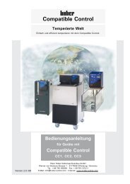
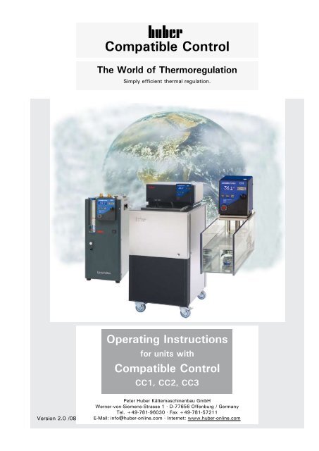
<strong>Compatible</strong> <strong>Control</strong><br />
The World of Thermoregulation<br />
Simply efficient thermal regulation.<br />
Operating Instructions<br />
for units with<br />
<strong>Compatible</strong> <strong>Control</strong><br />
CC1, CC2, CC3<br />
Peter Huber Kältemaschinenbau GmbH<br />
Werner-von-Siemens-Strasse 1 · D-77656 Offenburg / Germany<br />
Tel. +49-781-96030 · Fax +49-781-57211<br />
E-Mail: info@huber-online.com · Internet: www.huber-online.com
Symbols<br />
Safety<br />
Warning! A potentially hazardous situation. Identifies hazards sufficient<br />
to cause death or severe injuries if the safety instructions are<br />
disregarded.<br />
Caution! A potentially hazardous situation. Identifies hazards sufficient<br />
to cause light injuries if the safety instructions are disregarded.<br />
Definitions from our Huber Glossary<br />
and fundamental technical knowledge.<br />
Entries at the <strong>Compatible</strong> <strong>Control</strong> controller<br />
Service<br />
This is where you get help: the Huber Hotline<br />
EXTRA<br />
Additional information
Preface<br />
Dear Customer,<br />
Congratulations! Units and devices manufactured by Peter Huber<br />
Kältemaschinenbau GmbH are always a good choice.<br />
Thank you very much for your trust.<br />
To meet your demands as a user, we have revolutionized the user<br />
interface of our thermostats and implemented a uniform method of<br />
operating almost the entire <strong>HUBER</strong> product range. Many devices,<br />
ranging from small immersion thermostats to large Unichillers are<br />
operated via a single controller generation: <strong>Compatible</strong> <strong>Control</strong>.<br />
The units operated with the <strong>Compatible</strong> <strong>Control</strong> are listed in the following<br />
table with a remark for those which also have a supplementary<br />
instruction manual.<br />
On the type label on the rear of your device you will find important<br />
information such as:<br />
CC2-505wl vpc -50°... +200°C SNr.: 55655/03<br />
[Device Name] [Temperature range] [Serial Number]<br />
Free choice in operation:<br />
All the listed Units can be operated with three different controller<br />
versions:<br />
<strong>Compatible</strong> <strong>Control</strong> CC1, simple<br />
<strong>Compatible</strong> <strong>Control</strong> CC2, versatile<br />
<strong>Compatible</strong> <strong>Control</strong> CC3, dialogue<br />
You controller version is identified by the label above the display.<br />
For details on your type of controller, please refer to Chapter 2.2.<br />
Please consider only those instructions in the present documentation<br />
that apply to your device type and controller version.<br />
To avoid confusions:<br />
– <strong>Compatible</strong> <strong>Control</strong> CC1, <strong>Compatible</strong> <strong>Control</strong> CC2 or <strong>Compatible</strong><br />
<strong>Control</strong> CC3 means the removable controller only!<br />
– CC1-E, CC2-E or CC3-E means the complete immersion thermostat<br />
including the <strong>Compatible</strong> <strong>Control</strong>.
All units with no separate instruction manual are listed in the following table. They are included in the present<br />
manual.<br />
Combinations of immersion thermostats with baths and <strong>Compatible</strong> <strong>Control</strong> Thermostats with <strong>Compatible</strong><br />
<strong>Control</strong> CC1, CC2, CC3.<br />
<strong>Control</strong>ler CC1, CC2 und CC3 Please note: In the present manual the 3 controller options (CC1, CC2, CC3)<br />
are designated as „CCx“.<br />
CCx-E Immersion Thermostat<br />
CCx-E-BX Bridge Thermostat<br />
CCx-105A to CCx-118A Heating Bath Thermostat with Polycarbonate bath<br />
CCx-208B to CCx-225B Heating Thermostat with Stainless steel bath<br />
CCx-205B Heating Circulation Thermostat<br />
CCx-202C Heating Circulation Thermostat<br />
CCx-304B vpc Heating Bath- and Circulation Thermostat<br />
CCx-308B vpc Heating Bath- and Circulation Thermostat<br />
CCx-315B vpc Heating Bath- and Circulation Thermostat<br />
CCx-300B2X Bridge Thermostat<br />
CCx-300B4X Bridge Thermostat<br />
CCx-K6 Cooling Bath Thermostat<br />
CCx-K12 to CCx-K25 Cooling Bath Thermostat<br />
Minichiller 1-3/-H1 Chiller<br />
All units listed in the following table have a suplementary instruction manual. Please read the instructions in<br />
the other manual as well.<br />
<strong>Compatible</strong> <strong>Control</strong> Thermostats with <strong>Control</strong>ler CC1, CC2 and CC3<br />
Variostat CC Cooling and Heating Thermo-stat for variable bath sizes<br />
CCx-305 vpc Cooling and heating thermostats to -45°C<br />
CCx-405 vpc / CCx-405w vpc Cooling and heating thermostats to -45°C<br />
CCx-415 vpc / CCx-415wl vpc Cooling and heating thermostats to -45°C<br />
CCx-410wl vpc Cooling and heating thermostats to -45°C<br />
CCx-505 vpc / CCx-505wl vpc Cooling and heating thermostats to -55°C<br />
CCx-510 vpc / CCx-510w vpc Cooling and heating thermostats to -55°C<br />
CCx-515 vpc / CCx-515w vpc Cooling and heating thermostats to -55°C<br />
CCx-520w vpc Cooling and heating thermostats to -55°C<br />
CCx-525w vpc Cooling and heating thermostats to -55°C<br />
CCx-705 vpc Cooling and heating thermostats to -90°C<br />
CCx-805 vpc Cooling and heating thermostats to -90°C<br />
CCx-815 vpc Cooling and heating thermostats to -90°C<br />
CCx-820 vpc / CCx-820w vpc Cooling and heating thermostats to -90°C<br />
CCx-905 vpc / CCx-905w vpc Cooling and heating thermostats to -90°C
Unichiller with <strong>Compatible</strong> <strong>Control</strong> CC1, CC2 and CC3<br />
UC006A /-H Unichiller<br />
UC007 /-H Unichiller<br />
UC015 /-H to UC015w /-H Unichiller<br />
UC022 /-H to UC022w /-H Unichiller<br />
UC020 /-H to UC020w /-H Unichiller<br />
UC025 /-H to UC025w /-H Unichiller<br />
UC006T /-H Unichiller (air cooled bench models)<br />
UC009T /-H Unichiller (air cooled bench models)<br />
UC012T /-H Unichiller (air cooled bench models)<br />
UC016T /-H Unichiller (air cooled tower models)<br />
UC020T /-H Unichiller (air cooled tower models)<br />
UC025T /-H Unichiller (air cooled tower models)<br />
UC040T /-H Unichiller (air cooled tower models)<br />
UC045T /-H Unichiller (air cooled tower models)<br />
UC050T /-H Unichiller (air cooled tower models)<br />
UC055T /-H Unichiller (air cooled tower models)<br />
UC060T /-H Unichiller (air cooled tower models)<br />
UC080T /-H Unichiller (air cooled tower models)<br />
UC006Tw Unichiller (water cooled bench models)<br />
UC009Tw Unichiller (water cooled bench models)<br />
UC012Tw /-H Unichiller (water cooled bench models)<br />
UC015Tw /-H Unichiller (water cooled bench models)<br />
UC023Tw /-H Unichiller (water cooled bench models)<br />
UC016Tw /-H Unichiller (water cooled tower models)<br />
UC020Tw /-H Unichiller (water cooled tower models)<br />
UC025Tw /-H Unichiller (water cooled tower models)<br />
UC030Tw /-H Unichiller (water cooled tower models)<br />
UC040Tw /-H Unichiller (water cooled tower models)<br />
UC055Tw /-H Unichiller (water cooled tower models)<br />
UC060Tw /-H Unichiller (water cooled tower models)<br />
UC080Tw /-H Unichiller (water cooled tower models)<br />
Unichiller ETH WL Unichiller to operate under the workbench to be connected to an air-extract duct<br />
Hotbox HB1 Compact recirculator to maintain the temperature of externally open systems<br />
Hotbox HB2 Compact recirculator to maintain the temperature of externally open systems<br />
Hotbox HB3 Compact recirculator to maintain the temperature of externally open systems<br />
Hotbox HB4 Compact recirculator to maintain the temperature of externally open systems<br />
Hotbox HB5 Compact recirculator to maintain the temperature of externally open systems<br />
BFT1-2 Beer „Force Ageing“ Thermostat (with <strong>Compatible</strong> <strong>Control</strong> CC2 only)<br />
BFT1w-2 Beer „Force Ageing“ Thermostat (with <strong>Compatible</strong> <strong>Control</strong> CC2 only)<br />
BFT2-2 Beer „Force Ageing“ Thermostat (with <strong>Compatible</strong> <strong>Control</strong> CC2 only)<br />
BFT2w-2 Beer „Force Ageing“ Thermostat (with <strong>Compatible</strong> <strong>Control</strong> CC2 only)<br />
When contacting our service hotline please remember that the machine name and the serial number have to<br />
be indicated. This information is to be found on the type label on the rear of your device.
Important note:<br />
Grouping our products into „families“ to best present them for an easy overview has always been a priority.<br />
Now, with the expansion of the product range and the introduction of new technologies such as „VPC“<br />
(Variable Pump <strong>Control</strong>“) we have made some changes to simplify the range to make it easier for you to<br />
navigate your way to the best unit for your application.<br />
The „Polystat“ and „<strong>Compatible</strong> <strong>Control</strong>“ ranges have been merged into one family called the „<strong>Compatible</strong><br />
<strong>Control</strong> Thermostats“. The following table shows the new names for each product together with the old<br />
name.<br />
(„x“ stands for the controller variants CC1, CC2 and CC3)<br />
New Name Old Name<br />
<strong>Compatible</strong> <strong>Control</strong> CCx Polystat <strong>Control</strong> ccx (<strong>Control</strong>ler)<br />
CCx-E Polystat ccx (Immersion Thermostat)<br />
CCx-105A to CCx-118A Polystat A5 to A18<br />
CCx-208B to CCx-225B Polystat B8 to B25<br />
CCx-205B Polystat 202<br />
CCx-202C Polystat 201<br />
CCx-304B vpc CC301-x<br />
CCx-308B vpc CC302-x<br />
CCx-315B vpc CC303-x<br />
CCx-300B2X CC302BX-x<br />
CCx-300B4X CC303BX-x<br />
CCx-305 vpc CC130-x<br />
CCx-405 vpc / CCx-405w vpc CC241-x / CC241w-x<br />
CCx-415 vpc / CCx-415wl vpc CC240-x / CC240wl-x<br />
CCx-410wl vpc CC245wl-x<br />
CCx-505 vpc / CCx-505wl vpc CC250-x / CC250wl-x<br />
CCx-510 vpc / CCx-510w vpc CC150-x / CC150w-x<br />
CCx-515 vpc / CCx-515w vpc CC155-x / CC155w-x<br />
CCx-520w vpc CC156w-x<br />
CCx-525w vpc CC157w-x<br />
CCx-705 vpc CC175-x<br />
CCx-805 vpc CC180-x<br />
CCx-815 vpc CC185-x<br />
CCx-820 vpc / CCx-820w vpc CC181-x / CC181w-x<br />
CCx-905 vpc / CCx-905w vpc CC190-x / CC190w-x
Contents<br />
Preface<br />
1. Safety<br />
1.1 Intended Use<br />
General Safety Instructions 3<br />
2. Device Description<br />
2.1 Format 7<br />
2.2 <strong>Control</strong>ler 12<br />
3. Commissioning<br />
3.1 Safety Instructions and Principles 15<br />
3.2 Connecting Mains Power and Media 19<br />
3.3 Overtemperature protection 22<br />
3.4 Filling Thermofluid 24<br />
3.5 Major Pre-settings 28<br />
4. Thermoregulation via <strong>Control</strong>ler<br />
4.1 Safety Instructions and Principles 31<br />
4.2 Main Menu 33<br />
4.3 Editing Default Settings 34<br />
4.4 Limiting the Thermoregulation Range 44<br />
4.5 Calibration 45<br />
4.6 Utilities 47<br />
4.7 Enter a Setpoint - Start 48<br />
4.8 Convenient Thermoregulation - Programs 49<br />
4.9 Terminating the Thermoregulation Process 55<br />
5. Shut Down<br />
5.1 Safety Instructions and Principles 59<br />
5.2 Draining, Deactivating and Dismanting 60<br />
5.3 Maintenance, Service 62<br />
6. Appendix<br />
6.1 Presettings 65<br />
6.2 Interface Specification, Data Communication 66<br />
6.3 Device Messages 67<br />
Huber - Glossary 71
1. Safety<br />
1.1 Intended Use<br />
General Safety Instructions<br />
The thermostat is designed for industrial applications.<br />
The thermostat is used for direct and indirect thermoregulation, i.e. for<br />
heating or cooling external substances through suitable thermal fluids.<br />
It must be operated strictly in compliance with the operating instructions.<br />
The thermostat must not be modified by the plant operator or any<br />
operating personnel.<br />
The thermostat must not be used for purposes other than thermoregulation<br />
in compliance with the operating instructions.<br />
Unintended use or use not in compliance with the operating instructions<br />
may lead to severe personal injury or property damage.<br />
Your device has been designed and constructed according to the state<br />
of the art and in compliance with the generally accepted safety rules.<br />
Nonetheless, your device may constitute an imminent or unexpected<br />
hazard. For this reason, your device has been equipped with safety<br />
devices. Deactivating these safety devices bears high risks<br />
and invalidates the warranty.<br />
Use the device only if it is in good order and condition.<br />
Shut down the device immediately in the case of malfunctions or<br />
failures.<br />
Only qualified personnel is permitted to perform repairs.<br />
Do not bypass, bridge, dismount or deactivate any safety devices.<br />
The manufacturer assumes no liability for damage due to technical<br />
modifications, improper handling or use of the device disregarding the<br />
operating instructions.<br />
Warning! Risk of injuries!<br />
While operating at high temperatures, the bath lid and the housing<br />
could become very hot. Only touch the housing and the lid by the<br />
grips otherwise there is a risk of burns!<br />
Never lift the bath’s lid during operation at high temperature:<br />
- Risk of scald /burn through thermal fluid overflow.<br />
- Risk of caustic vapours causing injuries to the respiratory tract and/<br />
or skin!<br />
This warning is only applicable for units with this warning sign.<br />
Important: Transport damage!<br />
When unpacking the device, inspect it for transport damage.<br />
Please revert to the haulage contractor or shipping agent for settlement<br />
of claims.<br />
Commission a damaged device only after the damage has been<br />
repaired or you have ascertained the full effects of damage and the<br />
insurance agent/haulage contractor/shipping agent has given their<br />
permission.<br />
3
1. Safety<br />
1.1 Intended Use<br />
General Safety Instructions<br />
Duties of the Plant Operator<br />
� The operating instructions must be kept readily available in the<br />
immediate vicinity of the thermostat.<br />
� Only sufficiently qualified operating personnel are permitted to<br />
use the thermostat.<br />
� The operating personnel must be trained in handling and using<br />
the thermostat.<br />
� Verify that operating personnel have read and understood the<br />
operating instructions.<br />
� Precisely define the fields of responsibility of the operating<br />
personnel.<br />
� Provide protective clothing for the operating personnel.<br />
Requirements to be Met by the Operating Personnel<br />
� Only personnel assigned and trained by the plant operator may<br />
handle and operate the thermostat.<br />
� The minimum age for operating personnel is 16 years. Within the<br />
workspace, the device operator is responsible for third parties.<br />
� The device operator must be sufficiently qualified.<br />
Duties of the Operatorating Personnel<br />
� The operating personnel must read the operating instructions<br />
thoroughly before handling or using the thermostat.<br />
� The operating personnel must heed all the safety instructions.<br />
� The operating personnel must wear protective clothing when<br />
handling or using the thermostat.<br />
Workspace<br />
The workspace is defined to be at the control panel in front of the<br />
thermostat.<br />
The workspace is further defined by the peripheral equipment connected<br />
by the customer. The customer is responsible for taking suitable<br />
safety measures.<br />
Safety Devices<br />
� Over-temperature protection device<br />
� Low liquid level protection<br />
Protection Devices<br />
� Mains failure automatic<br />
� Alarm functions<br />
Emergency Plan – Switch off the Power Supply!<br />
Hazardous emission of fluid/vapor from the thermostat or connected<br />
pipes/hoses (very hot, very cold, hazardous chemical compositions)<br />
and or fire/explosion/implosion:<br />
Strictly heed the safety instructions of the plant operator relating<br />
to the risk of injury and danger to life as well as to the limitation of<br />
damage. Observe the instructions included in the safety data sheet of<br />
the respective thermal fluid!<br />
4
2. Device Description<br />
Due to technical developments the location of components<br />
may change.
1<br />
2<br />
3<br />
4<br />
5<br />
6<br />
7<br />
8<br />
9<br />
10<br />
11<br />
12<br />
13<br />
14<br />
15<br />
16<br />
17<br />
20<br />
21<br />
22<br />
23<br />
24<br />
25<br />
26<br />
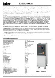
2. Device Description<br />
2.1 Format<br />
Removable, exchangeable<br />
<strong>Compatible</strong> <strong>Control</strong><br />
Power switch<br />
Over-temperature protection device<br />
Hood<br />
Hood fixing screws<br />
<strong>Control</strong>ler fixing screws<br />
Float (level protection)<br />
Internal control sensor<br />
Temperature sensor – over-temperature<br />
protection device<br />
Pressure pump<br />
with<br />
Stirrer<br />
Hose pressure connection for circulating<br />
thermal fluid from the thermostat<br />
to the external device<br />
Inlet for the pressure pump<br />
Heater<br />
Base plate<br />
Power supply<br />
Socket for cooling bath control<br />
ID plate<br />
Bath bridge #6309*<br />
Pump adapter for lateral attachment<br />
(hose connecting piece)*, for additional<br />
external thermoregulation<br />
Pump adapter for rear attachment<br />
(hose connecting piece)*, for additional<br />
external thermoregulation<br />
Cooling coil for mounting with lateral<br />
cooling water inlet and outlet connections*<br />
Cooling coil for mounting with rear<br />
cooling water inlet and outlet connectors*<br />
Screw clamp for fastening the <strong>Compatible</strong><br />
<strong>Control</strong> CC1-3 to a bath tank.<br />
Within the scope of technological<br />
progress and practicality, we reserve<br />
the right to change the location of<br />
individual components.<br />
*Can be ordered optionally for <strong>Compatible</strong><br />
<strong>Control</strong> CC1-3-E; for other<br />
accessories, please refer to the product<br />
catalog.<br />
Bad thermostats and circulators used as heating thermostats<br />
Models: <strong>Compatible</strong> <strong>Control</strong> CC1-3-E, CC1-3-300B2/4X<br />
The devices heat up to 200 °C.<br />
They are suitable for cooling with cooling water and through an<br />
externally connected cooler to -30°C.<br />
View of<br />
RH front<br />
side<br />
View of<br />
LH rear<br />
side<br />
4<br />
2<br />
20<br />
26<br />
8<br />
13<br />
10<br />
11<br />
14<br />
9<br />
7<br />
����<br />
1<br />
3<br />
15<br />
24<br />
13<br />
12<br />
22<br />
16<br />
17<br />
5<br />
6<br />
5<br />
23<br />
4<br />
5<br />
6<br />
5<br />
7<br />
14<br />
21<br />
25
1<br />
2<br />
3<br />
4<br />
5<br />
6<br />
7<br />
8<br />
9<br />
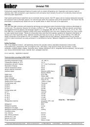
Removable, exchangeable<br />
<strong>Compatible</strong> <strong>Control</strong><br />
Main switch<br />
Bath<br />
Bath lid<br />
Front grip<br />
Bath outflow<br />
ID plate<br />
CAN-Interface<br />
Power supply<br />
10 Flow (circulation)<br />
11 Return (circulation)<br />
12 Connection for cooling coil<br />
13 Back grip<br />
14 POKO (Potential-Free Contact)<br />
15 AIF (Analog Interface)<br />
16 Enable<br />
17 RS232<br />
2. Device Description<br />
2.1 Format<br />
<strong>Compatible</strong> <strong>Control</strong> Thermostat CCx-304B vpc<br />
Bath and Circulation Thermostat<br />
Working Temperature Range (-20) 28...300°C.<br />
With Refrigerator -20...300°C.<br />
View of<br />
RH front<br />
side<br />
View of<br />
rear side<br />
2<br />
4<br />
3<br />
8<br />
14<br />
7<br />
11<br />
13<br />
CC 301<br />
1<br />
5<br />
6<br />
15<br />
16<br />
17<br />
8<br />
9<br />
10<br />
12
1<br />
2<br />
3<br />
4<br />
5<br />
6<br />
7<br />
8<br />
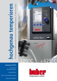
Removable, exchangeable<br />
<strong>Compatible</strong> <strong>Control</strong><br />
Main switch<br />
2. Device Description<br />
2.1 Format<br />
Overheating protection (not visible)<br />
Electric system box with swing door<br />
Lock of the electric system box door<br />
Keep the key at a safe place!<br />
<strong>Control</strong>ler attachment screws (both<br />
sides)<br />
Level indicator<br />
Expansion vessel with filler connection<br />
10 Air supply for pump motor<br />
20 ID plate<br />
21 Power supply without plug<br />
22<br />
23<br />
25<br />
Hose connection for circulating<br />
thermal fluid from the thermostat<br />
to the external application<br />
Hose connection for circulating<br />
thermal fluid from the external<br />
application to the thermostat<br />
24 Thermal fluid drain valve:<br />
24a fluid circulation pump draining<br />
connection<br />
24b for the evaporator draining connection<br />
Air grill with forced ventilation<br />
behind it<br />
30 Ring bolt (detachable eyebolt)<br />
31 Lockable wheels<br />
Unichiller (Chiller)<br />
Models: UC016T-3(-H), UC020T-3(-H), UC025T-3(-H),<br />
UC040T-3(-H) etc.<br />
The devices cool to -10/-20°C with air-cooled chiller<br />
H-devices are additionally equipped with a heater.<br />
H-devices heat up to 100°C.<br />
View of<br />
RH front<br />
side<br />
View of<br />
rear side<br />
9<br />
8<br />
5<br />
4<br />
5<br />
24a<br />
24b<br />
30<br />
20<br />
21<br />
25<br />
7<br />
1<br />
6<br />
2<br />
10<br />
8<br />
22<br />
23<br />
24<br />
31
1<br />
2<br />
3<br />
4<br />
5<br />
6<br />
7<br />
8<br />
9<br />
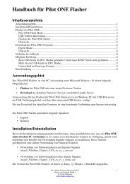
Removable, exchangeable<br />
<strong>Compatible</strong> <strong>Control</strong><br />
Main switch<br />
Draining connection<br />
Overflow connection<br />
Level indicator<br />
Filler connection<br />
Back grip<br />
Power supply<br />
Return (circulation output)<br />
10 Flow (circulation input)<br />
11 Cooling water inlet<br />
12 Cooling water outlet<br />
2. Device Description<br />
2.1 Format<br />
Unichiller (Chiller)<br />
minichiller 1-3 /-H1<br />
minichiller w-1-3<br />
Working temperature range minichiller 1-3: -20...40°C<br />
Working temperature range minichiller 1-3 with H1: -20...100°C<br />
Working temperature range minichiller w-1-3: -20...40°C<br />
View of<br />
RH front<br />
side<br />
View of<br />
rear side<br />
10<br />
5<br />
4<br />
3<br />
minichiller 1-3<br />
10<br />
9<br />
6<br />
CC 301<br />
10<br />
7<br />
8<br />
6<br />
1<br />
11<br />
2<br />
minichiller w 1-3<br />
12<br />
9<br />
8
1<br />
2<br />
3<br />
4<br />
5<br />
6<br />
7<br />
8<br />
9<br />
Removable, exchangeable<br />
<strong>Compatible</strong> <strong>Control</strong><br />
Main switch<br />
Draining connection<br />
Level indicator<br />
Filler connection<br />
Guard<br />
Draining pump<br />
Overflow connection<br />
Flow (circulation input)<br />
10 Return (circulation output)<br />
11 Back grip<br />
12 Power supply<br />
13 ID plate<br />
2. Device Description<br />
2.1 Format<br />
Unichiller (Chiller)<br />
Unichiller UC007-1-3 /-H<br />
Working temperature range UC007-1-3: -20...40°C<br />
Working temperature range UC007-1-3 with H: -20...80°C<br />
View of<br />
RH front<br />
side<br />
View of<br />
rear side<br />
11<br />
4<br />
3<br />
12<br />
11<br />
9<br />
5<br />
CC 301<br />
8<br />
13<br />
10<br />
1<br />
5<br />
7<br />
2<br />
6
Displays,<br />
<strong>Control</strong><br />
panel<br />
Connections<br />
Activity<br />
incidator<br />
LEDs<br />
2. Device Description<br />
2.2 <strong>Control</strong>ler<br />
<strong>Compatible</strong> <strong>Control</strong> CC1<br />
<strong>Compatible</strong> <strong>Control</strong> CC2<br />
<strong>Compatible</strong> <strong>Control</strong> CC3<br />
R1 Digital status display<br />
R2<br />
Prompt for a temperature setpoint,<br />
input confirmation (data<br />
transfer)<br />
R3 Call of the user menu for convenient<br />
handling<br />
R4 On/Off key to start/stop thermoregulation<br />
R5 Activity indicator LEDs<br />
R6 Over-temperature protection<br />
device<br />
R7 Encoder/ rotate:<br />
Entry of program numbers,<br />
step numbers, parameters<br />
(e.g. temperature set-point)<br />
Encoder/ press:<br />
Input confirmation (data transfer)<br />
R8 Pt100 sensor socket<br />
R9 RS 232/485 interface<br />
R10<br />
R51<br />
R52<br />
R53<br />
R54<br />
Fixing screw (on either side)<br />
for connecting the <strong>Compatible</strong><br />
<strong>Control</strong> to the thermostat<br />
Process temperature control active (green<br />
LED), only with CC2, CC3: Temperature is<br />
measured by a process sensor located at the<br />
point of control e.g. in a reactor.<br />
Heating active (yellow LED)<br />
Cooling/compressor active (blue LED)<br />
Pump active (green LED):<br />
Thermal fluid is being pumped through the<br />
connected application, e.g. around the reactor<br />
jacket.<br />
12<br />
R1<br />
R2<br />
R5<br />
R6<br />
R1<br />
R3<br />
R2<br />
R5<br />
R6<br />
R1<br />
R4<br />
R3<br />
R2<br />
R5<br />
R6<br />
R10<br />
R51<br />
R52<br />
R53<br />
R54<br />
R7<br />
R8<br />
R7<br />
R10<br />
R8<br />
R9<br />
R7<br />
R10
3. Commissioning
Prepara-<br />
tory<br />
Measures<br />
for Commissioning<br />
Postitioning<br />
Location<br />
3. Commissioning<br />
3.1 Safety Instructions and Principles<br />
Plan the thermoregulation target and procedure.<br />
Determine the device configuration and system structure.<br />
Select an appropriate thermal fluid.<br />
Selection criteria for thermal fluids: Temperature range of the thermostat,<br />
application restrictions building safety regulations, your projected<br />
working temperature, viscosity, flash point.Position the thermostat<br />
and external devices on a stable and even surface. Ensure that the<br />
surface can safely hold the weight of the thermostat and external<br />
equipment.<br />
Caution! Potential risk of injury and material damage:<br />
Keep the device upright during transport.<br />
Place the device in an upright and stable position and make sure that<br />
it cannot tilt over.<br />
Keep the vicinity of the device clean: Prevent slip and tilting hazards.<br />
Lock the wheels of floor-mounted devices once you have positioned<br />
them as desired!<br />
Useful note: Place appropriately large collecting trays under the thermostat<br />
and the application.<br />
The use of the device is only allowed in normal environment conditions<br />
according to DIN EN 61010-1:2001:<br />
– Use only in the inside<br />
– Hight up to 2000m<br />
– Place on a dense, level, non-slip and non-flammable surface.<br />
– Place the device at a distance to walls and the ceiling that permits<br />
sufficient air circulation (heat dissipation, supply of fresh air for<br />
the thermostat and the workspace). A water-cooled unit requires<br />
a minimum of 10 cm and an air-cooled unit needs a minimum of<br />
20 cm.<br />
– Ambient temperature min- 5°C to max. 32°C<br />
– Short distances to the supplies<br />
– The device souldn’t be placed such that the access to the mains<br />
could be obstructed<br />
– Mains voltage fluctuation do not exceed + 10% of the stated input<br />
voltage<br />
– Transient overvoltage like they usualy appear in the mains supply<br />
– Applicable degree of pollution: 2<br />
– Class of overvoltage: II<br />
– Protection Classification: IP20<br />
The workspace of the thermostat must comply with local safety regulations.<br />
Please Note:<br />
All the safety instructions are vital and must be considered during<br />
the operation of the unit in compliance with the operating instructions.<br />
15
DIN<br />
12876<br />
3. Commissioning<br />
3.1 Safety Instructions and Principles<br />
The operating instructions contain additional safety instructions.<br />
These are identified through a triangle with an exclamation mark.<br />
Thoroughly read and heed the instructions Non-observance may<br />
involve considerable consequences such as device damage, physical<br />
damage or personal injury with fatal consequences.<br />
Workspace<br />
The workspace is defined to be at the control panel in front of the<br />
thermostat. The workspace is further defined by the peripheral equipment<br />
connected by the customer. The customer is responsible for<br />
taking suitable safety measures.<br />
Safety devices<br />
– Overtemperature protection<br />
– Low liquid level protection<br />
– Mains failure automatic<br />
– Alarm functions<br />
Hazardous emission of fluid/vapour from the thermostat or connected<br />
pipes/hoses (very hot, very cold, hazardous chemical compositions)<br />
and or fire/explosion/implosion: Strictly heed the safety instructions<br />
of the plant operator relating to the risk of injury and danger to life as<br />
well as to the limitation of damage.<br />
Observe the instructions included in the safety data sheet of the<br />
respective Thermofluid!<br />
Class designation Fluid for thermoregulation Technical requirements Designation d<br />
I non-combustible a Overheating protection c NFL<br />
II combustible b Adjustable overheating protection FL<br />
III combustible b Adjustable overheating protection<br />
and additional low level protection<br />
a Generally water, other fluids only if they are not combustible<br />
in the temperature range of an individual fault.<br />
b The fluid for thermoregulation must have a burning point<br />
of > 65°C; this means that ethanol can only be used under<br />
supervision.<br />
c The overheating protection can be achieved e.g. through an<br />
appropriate fill level sensor or appropriate temperature control<br />
devices.<br />
d Optional, depending on the manufacturer’s choice.<br />
Your thermostat complies with the class designation III / FL<br />
We cannot guarantee the suitability of our components (individually<br />
or combined) for use in a potentially explosive environment.<br />
Not suitable for use as a medical appliance (e.g. in vitro diagnosis<br />
methods).<br />
Please Note:<br />
All the safety instructions are vital and must be considered during<br />
the operation of the unit in compliance with the operating instructions.<br />
16<br />
FL
Thermal<br />
fluid<br />
Hazards<br />
during<br />
thermo-<br />
regulation<br />
3. Commissioning<br />
3.1 Safety Instructions and Principles<br />
Only non-flammable thermal fluids are permissible for unattended<br />
operation!<br />
Requirements for thermal fluids classified as III / FL:<br />
EN 61010-1: Maximum permissible working temperature 25°C below<br />
the flash point!<br />
Maximum viscosity at the lowest working temperature: 50mm²/s!<br />
Maximum density of the thermal fluid: 1kg/dm³.<br />
Possible thermoregulation range within the range of the planned minimum<br />
and maximum working temperature.<br />
Do not use thermal fluids with any of the additives ether, ester or<br />
amine. Do not use demineralized water, mineral water, sea water or<br />
CaCl2 brines!<br />
Compatibility with the materials of the thermostat (stainless steel<br />
1.4301 (V2A) and Viton) and all materials of the connected application.<br />
A selection of thermofluids and their technical data is to be found in<br />
the current Huber catalogue.<br />
Caution! Potential risk of injury and material damage during thermoregulation:<br />
In the course of operation of the thermostat, extreme changes in temperature<br />
and pressure and the specific characteristics of the thermal<br />
fluids used may constitute hazards.<br />
Please Note:<br />
All the safety instructions are vital and must be considered during<br />
the operation of the unit in compliance with the operating instructions.<br />
17
Hazards<br />
through<br />
emission<br />
of fluids<br />
Hazards<br />
through<br />
emission<br />
of gases<br />
3. Commissioning<br />
3.1 Safety Instructions and Principles<br />
Caution! Potential risk of injury and material damage:<br />
The floor will be slippery when fluids have been spilt!<br />
Thermal fluids with a low flash point constitute a fire hazard!<br />
Hazard of scalding/burning when touching exposed or defective<br />
connections that are hot.<br />
Prevent overflow of the sight glass. (A site glass is not fitted to<br />
open-bath units. This refers to the UCO range and other Chillers)<br />
Prevent leaking fluid-conveying pipes/tubes and connections.<br />
Always remove any liquids spilt on the floor immediately.<br />
Always clean contaminated devices immediately.<br />
Place an appropriately large collecting tray under your external<br />
application.<br />
Caution! Potential risk of injury and material damage:<br />
Risk of causticization of your respiratory tracts and skin through<br />
vapors!<br />
Prevent leaks on closed external devices.<br />
Ensure good aeration and ventilation in the vicinity of the thermostat.<br />
Choose thermal fluids for thermoregulation that are not detrimental<br />
to health.<br />
18
Connecting<br />
power<br />
3. Commissioning<br />
3.2 Connecting Mains Power<br />
and Media<br />
Check the fuse, power and voltage ratings according to the Data<br />
Sheet (Appendix) and the type plate (on the rear of the device).<br />
Thermostats designed for use with three-phase current are supplied<br />
without a power plug.<br />
In the country of use, an appropriately trained and qualified electrician<br />
must fit the power cable with a suitable power plug.<br />
Caution!<br />
Please check the rotating field of your mains supply before connecting<br />
the plug.<br />
Your thermostat must be wired in accordance with a dextrorotatory<br />
field and the cable markings.<br />
Connect the power plug<br />
to the power outlet.<br />
* Figure applies in the<br />
country of manufacture<br />
(Germany) only.<br />
Shock-proof plug*<br />
for single-phase alternating current<br />
Plug for three-phase current*<br />
Warning! Hazard through electric current!<br />
Exclusively appropriately trained electricians are permitted to replace<br />
plugs, change the voltage in compliance with the Data Sheet and perform<br />
permanent installations.<br />
Otherwise there is a risk of injury and danger to life.<br />
19
Preparing<br />
the<br />
thermostat<br />
for use<br />
Thermal<br />
Fluid<br />
Prepara-<br />
tory<br />
measures<br />
for thermal<br />
fluid<br />
circulation<br />
3. Commissioning<br />
3.2 Connecting Mains Power<br />
and Media<br />
Applies to bath thermostats with external pump connection<br />
For internal thermoregulation, please proceed as follows:<br />
close the pump connections with plugs and sleeve nuts (M16x1 /<br />
19 spanner/wrench), at the same time hold against it at the pump<br />
connection with 17 spanner/wrench.<br />
For external thermoregulation, please proceed as follows:<br />
remove the plugs and sleeve nuts on the pump connections.<br />
Replace them with appropriate hose connection to your external<br />
application.<br />
For more information please see chapter 4 „thermoregulation via<br />
controller“.<br />
Applies to chillers (thermostats with closed external circulation)<br />
R2<br />
R2<br />
Make sure that the draining valve<br />
is closed. (Upright position or<br />
„right stop“).<br />
Connect hoses at connecting<br />
pieces 10 and 11 for circulating<br />
thermal fluid to and from the<br />
external device (if fitted).<br />
Note:<br />
Recommended tightening torques<br />
for hose couplings when using silicone<br />
oil as thermal fluid:<br />
M16x1 30 Nm<br />
M30x1.5 85 Nm<br />
Alternative:<br />
Hoses can be connected via shut-off valves.<br />
(Please refer to your Huber catalogue under<br />
„accessories“). If fitted, close valves only<br />
when performing work on the reactor.<br />
Remember that thermal fluid expands and<br />
contracts with changes in temperature.<br />
Sealing the external application will expose<br />
the application to these forces!<br />
20<br />
12<br />
12<br />
open<br />
close<br />
10 11<br />
Verify the following:<br />
Make sure that all connections are correct and that there are no leaks.<br />
For water-cooled thermostats:<br />
Unobstructed inflow and outflow of the cooling-water exists<br />
Pressure difference between the cooling-water inflow and outflow is<br />
3 to 5 bar. Cooling-water supply temperature is 15°C to 25°C.
MEDIA<br />
Prepara-<br />
tory<br />
measures<br />
for water<br />
cooling<br />
Prepara-<br />
tory<br />
measures<br />
for cooling<br />
baths<br />
CCx-K12<br />
to<br />
CCx-K25<br />
3. Commissioning<br />
3.2 Connecting Mains Power<br />
and Media<br />
Applies to water-cooled thermostats only<br />
4.1<br />
4.2<br />
1<br />
2<br />
3<br />
4<br />
Using suitable hosing,<br />
connect the Huber watercooled<br />
unit to the cooling<br />
water supply via connections<br />
26 and 27.<br />
Open all the water supply<br />
valve slowly and check<br />
for leaks.<br />
26 27<br />
Mains supply*<br />
(from <strong>Compatible</strong> <strong>Control</strong> CC-E<br />
to cooling bath)<br />
<strong>Control</strong> connection*<br />
(from <strong>Compatible</strong> <strong>Control</strong> CC-E<br />
to cooling bath)<br />
Main switch<br />
I = On (continuous duty of the<br />
cooling machine)<br />
0= Off<br />
II= „Auto.“ the compressor is<br />
automatically controlled<br />
Mains supply<br />
2 3<br />
(fuse protected)<br />
1<br />
Rear side of CC-K12<br />
* These connectors have to be plugged in even if the cooling bath<br />
is not being automatically controlled, otherwise the error message<br />
„SENSOR COND.!!“ will be displayed (refer to error code -11,<br />
6.3 Device Messages - Soft Alarms).<br />
21<br />
����<br />
Rear side of<br />
<strong>Compatible</strong> <strong>Control</strong> CC-E<br />
(Immersion Thermostat)<br />
4
Overtemperature<br />
protection<br />
Requirements<br />
Mechanicalovertemperature<br />
protection<br />
CC1, CC2,<br />
CC3<br />
105A to 118A<br />
208B to 225B<br />
202C, 205B<br />
K6 to K25<br />
3. Commissioning<br />
3.3 Overtemperature protection<br />
Prepare the thermostat for thermoregulation<br />
and take safety measures as described<br />
below:<br />
Setting the overtemperature protection<br />
device.<br />
Requirements:<br />
A suitable thermal fluid has been selected<br />
for the process requirements. The flash<br />
point of the thermal fluid is known.<br />
Procedure:<br />
The over-temperature protection is set to<br />
at least 25 °C below the flash point of the<br />
thermofluid.<br />
Caution:<br />
The overtemperature protection is an<br />
especially important safety device of your<br />
thermostat. It must always be operable<br />
and be tested periodically!<br />
If the actual value exceeds the set overtemperature<br />
limit, an alarm is triggered and<br />
the thermostat will cut-out the thermoregulation<br />
process. This process can be restarted<br />
only after the cause of the alarm has<br />
been eliminated and the alarm message<br />
acknowledged. Refer to 3.1 Principles and<br />
Safety Instructions!<br />
Setting the overtemperature protection<br />
When: Immediately after filling the system with thermofluid, ref. to 3.4!<br />
Recommendation:<br />
Periodically test the function of the overtemperature protection by<br />
entering a higher setpoint, e.g. as follows:<br />
- Set the overtemperature protection to 30°C,<br />
- Enter the new setpoint of 33°C,<br />
- Start Temperature <strong>Control</strong>.<br />
The thermoregulation process will be stopped automatically with the<br />
error message „Temp“. Make sure that the temperature does not continue<br />
to increase. The test of the overtemperature protection has been<br />
completed. Set the overtemperature protection to the desired temperature.<br />
The thermostat is ready for use once it has been switched off<br />
and back on again.<br />
For <strong>Compatible</strong> <strong>Control</strong> CC1-E, CC2-E,<br />
CC3-E (immersion thermostat), CCx-E with<br />
polycarbonate bath 105A to 118A,<br />
heating bath thermostats 208B to 225B,<br />
heating thermostat 202C and 205B,<br />
cooling heating bath K6 to K25,the overtemperature<br />
protection is set mechanically.<br />
It is independent of the controller.<br />
Use a suitable tool (screw driver or the like)<br />
to turn the red button in the center of the<br />
overtemperature protection device (section<br />
2.2) to the desired temperature value.<br />
22<br />
Working temperature range<br />
of thermostat (max.)<br />
Flash point of the thermal<br />
fluid<br />
Over-temperature<br />
protection (Overheat)<br />
Permissible temperature<br />
range for set-point entry<br />
Viscosity limit of the<br />
thermal fluid<br />
Working temperature range<br />
of thermostat (min.)<br />
Mechanical overtemperature<br />
protection<br />
Temperature rise
Electronic<br />
overtemperature<br />
protection<br />
for all units<br />
not listed<br />
above<br />
3. Commissioning<br />
3.3 Overtemperature protection<br />
For all other units not listed above, the overtemperature protection is<br />
set electronically. It is independent of the controller.<br />
Use a suitable tool (screw driver or the like) to press the button in the<br />
center of the overtemperature protection device.<br />
The overtemperature protection menu will be displayed.<br />
Over temp. protection<br />
OT Setpoint Heating<br />
ÜT Temp. display<br />
Exit<br />
OT Setpoint: Overtemperature value<br />
(adjustable at the controller, refer to 2.2).<br />
OT Temperature Display: Display of the overtemperature actual value.<br />
23
Fill the<br />
bath<br />
3. Commissioning<br />
3.4 Filling Thermofluid<br />
Bath and heating thermostat<br />
CCx-304B vpc<br />
Lift the bath lid.<br />
Fill in the thermofluid.<br />
Optimum liquid level:<br />
3 cm below bath<br />
opening.<br />
Close the bath lid.<br />
Please note that the medium<br />
should cool down to<br />
room temperature before<br />
you add thermofluid!<br />
Warning! Risk of injuries!<br />
While operating at high temperatures, the bath lid and the housing<br />
could become very hot. Only touch the housing and the lid by the<br />
grips otherwise there is a risk of burns!<br />
Never lift the bath’s lid during operation at high temperature:<br />
– Risk of scald /burn through thermal fluid overflow.<br />
– Risk of caustic vapours causing injuries to the respiratory tract<br />
and/or skin!<br />
24
Switch on<br />
Open,<br />
Fill<br />
UC016T-3<br />
UC020T-3<br />
UC025T-3<br />
UC040T-3<br />
etc.<br />
also all<br />
UCs with<br />
heating (-H)<br />
Terminate<br />
filling,<br />
close<br />
3. Commissioning<br />
3.4 Filling Thermofluid<br />
Unichiller (Chiller)<br />
Models: UC016T-3(-H), UC020T-3(-H), UC025T-3(-H),<br />
UC040T-3(-H) etc.<br />
Condition:<br />
make a hose connection to your<br />
external application.<br />
L1 Switch on the main switch.<br />
L2 Lift the bath lid.<br />
L3 Fill in the Thermofluid.<br />
The thermofluid flows from the<br />
expansion vessel into the thermostat<br />
than through the hose connections<br />
to the external application.<br />
Support the distribution process with<br />
the program „Venting“ (4.6.2).<br />
Continue filling procedure and<br />
„Venting“, until Gases are fully<br />
displaced off the System and the<br />
level on the luminescent display<br />
stays constant at 20-40%.<br />
Optimal level: 20-40%.<br />
The liquid level on the luminescent<br />
display stays constant on reaching<br />
of the optimal level.<br />
Stop „Venting“ Program.<br />
Close the bath lid.<br />
Caution! Potencial risk of injury and material damage!<br />
A proper venting is the condition for a troublefree operation. Commissioning<br />
often means a change of liquid.<br />
The manufacturer mostly uses other thermofluids as the user during<br />
the test run. Despite thorough draining, smallest residual could remain<br />
in the circuit and degasify after filling a new fluid and the beginning<br />
of the thermoregulation.<br />
The concequence of the above described and an incomplete venting<br />
could be an increasing presure that leads to sudden discharge of fluid<br />
and vapours!<br />
This danger can be prevented to a large extend with the „Venting“<br />
program.<br />
Change of liquid refer to 4.6.2., program „venting“!<br />
Absolutely pay attention to a thorough degasification at the beginning<br />
of the thermoregulation!<br />
25<br />
L2<br />
L3<br />
L1
Fill the<br />
thermostat<br />
3. Commissioning<br />
3.4 Filling Thermofluid<br />
Chiller<br />
minichiller 1-3 /-H1<br />
minichiller w-1-3<br />
Please note:<br />
The thermostat is fitted out with an<br />
overfill protection. When the fluid level<br />
exceeds the max mark in the sightglass,<br />
the fluid begins to outflow from<br />
the overflow connection (4).<br />
An overflow of the internal tank (which<br />
could flood the machine internals) can<br />
thus be avoided.<br />
Warning:<br />
The overflow connection (4) should never<br />
be closed, the fluid should be able to<br />
flow out without hindrance. However it<br />
is recommended with frequent change of<br />
the liquid or the application and/or with<br />
the first commissioning to put a hose on<br />
the overflow connection and to place the<br />
other end into a suitable receiver.<br />
Make a hose connection to your external application and make sure<br />
that everything is leakproof.<br />
Take off the lid of the filler connection (6) and slowly fill the thermal<br />
fluid.<br />
The fluid level should allways be between MIN and MAX on the level<br />
indicator.<br />
Switch the unit on with the main switch (2). The thermostat starts<br />
circulation and the fluid is pumped into your application. If there is no<br />
fluid in the application yet, the level in the Minichiller will lower continualy,<br />
please refill with fluid untill the level stays constant.<br />
26<br />
4<br />
2<br />
6
Fill the<br />
thermostat<br />
3. Commissioning<br />
3.4 Filling Thermofluid<br />
Unichiller (Chiller)<br />
UC007 1-3<br />
Please note:<br />
The thermostat is fitted out with an overfill<br />
protection. When the fluid level exceeds<br />
the max mark in the sight-glass, the fluid<br />
begins to outflow from the overflow connection<br />
(8). An overflow of the internal<br />
tank (wich could flood the machine internals)<br />
can thus be avoided.<br />
Warning:<br />
The overflow connection should never be<br />
closed, the fluid should be able to flow out<br />
without hindrance. However it is recommended<br />
with frequent change of the liquid<br />
or the application and/or with the first<br />
commissioning to put a hose on the overflow<br />
connection and to place the other end<br />
into a suitable receiver.<br />
Make a hose connection to your external<br />
application and make sure that everything is<br />
leakproof.<br />
Take off the lid of the filler connection (5) and<br />
slowly fill the thermal fluid.<br />
The fluid level should allways be between<br />
MIN and MAX on the level indicator.<br />
Switch the unit on with the main switch (2).<br />
The thermostat starts circulation and the fluid<br />
is pumped into your application. If there is<br />
no fluid in the application yet, the level in the<br />
Unichiller will lower continualy, please refill<br />
with fluid untill the level stays constant.<br />
27<br />
8<br />
2
Language<br />
Deutsch<br />
Setpoint<br />
Minimum<br />
Setpoint<br />
Maximum<br />
Setpoint<br />
3. Commissioning<br />
3.5 Major Pre-settings<br />
When delivered the controller displays will be in German.<br />
Other options can be selected in the „Language“ menu (refer to<br />
4.3.2): English, Francais<br />
The thermostat controls the temperature to the predefined setpoint.<br />
Use the SET key and the encoder to select other options.<br />
The permissible setpoints are limited to the range of the minimum and<br />
maximum setpoints.<br />
The option „setpoint limit“ allows this range to be modified.<br />
Notes to temperature range limit<br />
– Do not select the limits greater than needed.<br />
– Observe the characteristics of the thermal fluid (viscosity,<br />
flashpoint).<br />
– Consider the defaults of your application’s manufacturer.<br />
The programs for operating the thermostat are described in Chapter 4<br />
of the Operating Instructions.<br />
28
4. Thermoregulation<br />
via <strong>Control</strong>ler<br />
At work
Checks<br />
to be performed:<br />
Test<br />
Arrangement<br />
4. Thermoregulation<br />
via <strong>Control</strong>ler<br />
4.1 Safety Instructions<br />
and Principles<br />
Safety Instructions<br />
Compare the device configuration, the system structure and the selected<br />
thermofluid to the thermoregulation target.<br />
Verify the stability of the thermostat and external devices.<br />
Make sure there are no leaking connections.<br />
Make sure the shut-off valves for thermofluid and cooling water (if appli-<br />
cable) have been opened.<br />
Check the connection to the power supply.<br />
Caution! Potential risk of injury and material damage:<br />
Slip hazard! The floor and the workspace may be slippery when fluids<br />
have been spilt!<br />
Tilt hazard! Make sure the thermostat and external devices are in a stable<br />
position.<br />
Shock hazard! Make sure the connection to the power supply is<br />
undamaged and in perfect working order.<br />
Scalding and burning hazard! Always be aware of extreme temperatures.<br />
Causticization hazard! Risk of causticization of your eyes, your skin and<br />
your respiratory tracts through hazardous vapors (depends on the thermofluid<br />
used).<br />
Entering the minimum and maximum setpoints:<br />
In combination with the working temperature range limits, the minimum<br />
and maximum setpoints provide additional safety for the thermoregulation<br />
process. This means, accidental entry of a setpoint that is too low or too<br />
high will be rejected.<br />
Low liquid level protection:<br />
Monitor the liquid level during operation.<br />
Fill level to approx. 60-80 % of the bath height.<br />
Thermofluid level too low: Risk of the thermostat pump running dry.<br />
The controller will report an error and stop the thermoregulation process.<br />
Thermofluid level too high: Overflow, soiling, slip and causticization hazard!<br />
Change of fluid:<br />
Rinsing fluid and thermofluids come into contact with stainless steel<br />
(V2A), Viton and Perbunan and must be compatible with these materials.<br />
Room ventilation:<br />
Sufficient aeration and venting in the vicinity of the thermostat minimizes<br />
the risk of overheating and the accumulation of harmful gases and vapors.<br />
Please note:<br />
All the safety instructions are vital and must thus be considered on the job<br />
in compliance with the present operating instructions.<br />
31
Salutation<br />
Flash<br />
displays<br />
on the<br />
controller<br />
Operating<br />
the<br />
controller<br />
Messages<br />
4. Thermoregulation<br />
via <strong>Control</strong>ler<br />
4.1 Safety Instructions<br />
and Principles<br />
Manufac-<br />
turer<br />
Salutation<br />
System<br />
Test<br />
Status<br />
display<br />
Principles of displays and entries<br />
The status display depends on the preset display mode (refer to 6.1).<br />
Select the<br />
Main Menu<br />
Electronics test<br />
Memory Test<br />
Pump Test<br />
CC 505<br />
3 04.00a<br />
Name of thermostat,<br />
Software version<br />
Internal<br />
Process<br />
or or<br />
Select The display will<br />
a menu change upon turning<br />
option of the encoder Confirm<br />
your entry1) 1) If you fail to confirm your entry within 4 minutes, your selection will<br />
not be saved. The program returns to the status display.<br />
To exit the menu instantaneously at any point, use the Break function:<br />
Press the SET and MENU keys simultaneously. Your selection will not<br />
be saved.<br />
During operation, ad-hoc messages may be displayed on the controller.<br />
They provide information on irregularities and hazards in the thermostat.<br />
In the case of imminent danger, the controller will display a message<br />
and stop the thermoregulation process/switch off the thermostat at<br />
the same time (see 6.3).<br />
On/Off Press the On/Off key to start/stop the thermoregulation process<br />
(thermoregulation combined with circulation).<br />
Alternative:<br />
MasterClear function: Pressing the MENU and TEMP keys simultaneously<br />
stops a thermoregulation program in progress and switches off<br />
the analog interface or switches from the digital interface.<br />
Note:<br />
To learn more about the menu and the individual menu options, please<br />
also read sections 4.2 to 4.6 of the operating manual. The default<br />
settings can be found in Appendix 6.1 of the manual. All messages with<br />
expalnations of how to deal with the problems can also be found in<br />
the Appendix 6.2 of the manual. Definitions are in Appendix 6.4 of the<br />
manual.<br />
* Applies to <strong>Compatible</strong> <strong>Control</strong> CC2 and CC3 only<br />
** Applies to <strong>Compatible</strong> <strong>Control</strong> CC3 only<br />
32<br />
CC 505<br />
-50.0 200.0<br />
Name of thermostat,<br />
Working temperature range<br />
Internal 17.5 C<br />
Process<br />
n.a.<br />
Setpoint<br />
20.0 C<br />
Stored<br />
or<br />
Denied<br />
Flash display,<br />
return to the<br />
status display
Selection<br />
4. Thermoregulation<br />
via <strong>Control</strong>ler<br />
4.2 Main Menu<br />
Contents<br />
The main menu provides menu options and submenu options including<br />
all the settings and selections required to operate the thermostat<br />
(refer to 4.1!). The overtemperature menu is accessed by pressing the<br />
overtemperature button.<br />
1) This menu option is not available for <strong>Compatible</strong> <strong>Control</strong> CC1.<br />
2) This menu option is not available for <strong>Compatible</strong> <strong>Control</strong> CC2.<br />
Main Menu Submenus<br />
Page<br />
47<br />
36<br />
36<br />
39,40<br />
35<br />
41<br />
47<br />
38<br />
37<br />
45<br />
35<br />
46<br />
42<br />
50-53<br />
54<br />
49<br />
43<br />
37<br />
44<br />
34<br />
34<br />
55<br />
34<br />
47<br />
43<br />
43<br />
34<br />
35<br />
MAIN MENU:<br />
I-> 2nd Setpoint<br />
Alarm Clear<br />
Alarm Config.<br />
Analog-Interface<br />
Display<br />
Digit. Interface<br />
Venting<br />
Machine Options<br />
Max. Heat Power<br />
Calibration Prog.<br />
Mains Failure Auto<br />
Offset Calibration<br />
PI-Parameters<br />
Edit Program<br />
Program Start/Stop<br />
Start Ramp<br />
Acoustic Alarm<br />
Software version<br />
Setpoint Limits<br />
Language<br />
Temperature Scale<br />
Terminating Thermoreg.<br />
<strong>Control</strong> Mode<br />
Circulation<br />
Select Usermenu<br />
Config Usermenu<br />
Factory Default<br />
Time Scale<br />
Exit<br />
33<br />
I-> ALARM CONFIGURATION:<br />
I-> Alarm Mode<br />
Lower Alarm Limit<br />
Upper Alarm Limit<br />
Level Alarm Delay<br />
Exit<br />
I-> DISPLAY:<br />
I-> Display modes<br />
optimise display<br />
Options<br />
Exit<br />
I-> Digit. Interface:<br />
I-> Hardware RS<br />
Baud rate<br />
Protocol<br />
slave address<br />
Exit<br />
I-> 2-P.CALIBR.:<br />
I-> Edit TCal1<br />
Edit TCal2<br />
<strong>Control</strong> to TCal1<br />
<strong>Control</strong> to TCal2<br />
Exit<br />
I-> OFFSET CALIBRATION:<br />
I-> internal sensor<br />
process sensor<br />
Exit<br />
I-> INITIALISE:<br />
I-> Unit Data<br />
User menus<br />
Programmer<br />
All together<br />
Exit
Factory<br />
Default<br />
Language<br />
Temperature<br />
Scale<br />
<strong>Control</strong><br />
Mode<br />
4. Thermoregulation<br />
via <strong>Control</strong>ler<br />
4.3 Editing Default Settings<br />
1. Restoring the factory default<br />
2. Selecting a language for the controller display<br />
3. Temperature scale<br />
4. <strong>Control</strong> mode – internal, process (cascade)<br />
All the factory defaults can be customized in the menu.<br />
All the factory defaults can be restored via the „Factory Default“<br />
option (with the thermoregulation function switched off). For this purpose,<br />
proceed as described below. (Also refer to „Salutation“ 4.1).<br />
MAIN MENU:<br />
Config User<br />
I-> Factory default<br />
Time scale<br />
INITIALISE:<br />
I->Unit Data<br />
Programmer<br />
User menus<br />
All together<br />
Exit<br />
INITIALISE:<br />
User menus<br />
I->All together<br />
Exit<br />
MAIN MENU:<br />
Set-point limits<br />
I->Language<br />
Temperature Scale<br />
Language:<br />
I->Deutsch<br />
English<br />
Francais<br />
MAIN MENU:<br />
Language<br />
I->Temperature Scale<br />
Temperiermodus<br />
Temperature Scale:<br />
I->Celsius<br />
Fahrenheit<br />
Kelvin<br />
MAIN MENU:<br />
Temperature Scale:<br />
I-><strong>Control</strong> mode<br />
Umwälzen<br />
<strong>Control</strong> mode:<br />
I->Internal<br />
Process (Cascade)<br />
„Factory Default“ option<br />
Submenu selection:<br />
„Unit Data“: Important if you replaced device<br />
components or accessories.<br />
„Programmer“<br />
Deletion of all the thermoregulation programs<br />
incl. ramps entered by the customer.<br />
„User menus“<br />
Restores the „User menu“ factory default.<br />
„All together“<br />
Restores all the factory defaults.<br />
Caution! All the thermoregulation programs<br />
incl. ramps entered by the customer will be<br />
deleted!<br />
„Exit“ option:<br />
The factory defaults will not be restored.<br />
For selecting the language that is to be displayed<br />
on the controller.<br />
For selecting the temperature unit for display<br />
on the controller.<br />
Not available for <strong>Compatible</strong> <strong>Control</strong> CC1!<br />
For selecting the control mode, either Internal<br />
or Process (Cascade).<br />
For definitions of internal and external thermoregulation, please refer<br />
to Appendix 6.3. Huber Glossary, keyword <strong>Control</strong> Mode – Internal,<br />
Process (Cascade)!<br />
34
Display<br />
Time Scale<br />
Mains Failure<br />
Auto<br />
4. Thermoregulation<br />
via <strong>Control</strong>ler<br />
4.3 Editing Default Settings<br />
5. Display<br />
6. Time scale<br />
7. Mains failure auto<br />
MAIN MENU:<br />
Digit. Interface<br />
I-> Display<br />
Edit Program<br />
DISPLAY:<br />
I->Display mode<br />
optimise display<br />
display<br />
Exit<br />
DISPLAY MODES:<br />
Standard<br />
I->Double<br />
Doublel+Setp.<br />
Doublel+OT<br />
Options<br />
Service1<br />
Service2<br />
Service3<br />
exit<br />
DISPLAY:<br />
Display modes<br />
-> optimise display<br />
Exit<br />
Please Enter:<br />
Optimise display<br />
2<br />
MAIN MENU:<br />
Temperature Scale<br />
I->Time Scale<br />
Venting<br />
TIME SCALE:<br />
Seconds<br />
I->Minutes<br />
MAIN MENU:<br />
PI-Parameters<br />
I->PowerOff AutoStart<br />
Select Usermenu<br />
POWEROFF AUTOSTART.:<br />
I->Off<br />
On<br />
„Display“ option<br />
Selection in the „Display Modes“ submenu:<br />
„Standard“:<br />
Single-line status display, the actual value of<br />
the controller temperature (according to the<br />
control mode (internal or process temperature)<br />
is displayed in maximum font size.<br />
„Double“:<br />
Double-line status display, the actual values<br />
of the internal temperature and the (external)<br />
process temperature are displayed in medium<br />
font size.<br />
„Double+Setp“:<br />
Three-line status display, the actual values<br />
of the internal temperature and the process<br />
temperature as well as the setpoint are<br />
displayed in small font size.<br />
„Double+OT“:<br />
Three-line status display, the actual values<br />
of the internal temperature and the process<br />
temperature as well as the overtemperature<br />
setpoint are displayed in small font size.<br />
Options:<br />
Additionally in the third line of the display,<br />
depending on the unit and the mode of operation,<br />
the pump speed or the resulting value<br />
from the analogue output will be<br />
displayed.<br />
„Service1“ , „Service2“ and „Service3“:<br />
Service related variable status display.<br />
Selection in the „Display Angle“ submenu:<br />
Selection of a value to change the display<br />
angle by turning the encoder.<br />
„Time scale“: option<br />
Select the unit on which the timing of the<br />
thermoregulation programs is to be based.<br />
(Only available for CC2 and CC3!)<br />
„Mains Failure Auto“ option<br />
„Off“ After mains failure, manual input is<br />
required to continue the thermoregulation<br />
process.<br />
„On“ After mains failure, the thermoregulation<br />
process is continued automatically. The<br />
setpoint programmed last will be used for<br />
thermoregulation.<br />
35
Alarm<br />
Configu-<br />
ration<br />
Alarm<br />
Clear<br />
4. Thermoregulation<br />
via <strong>Control</strong>ler<br />
4.3 Editing Default Settings<br />
8. Alarm Configuration<br />
9. Alarm Clear<br />
Alarm: Read the alarm message - eliminate the cause - acknowledge<br />
the message (alarm clear).<br />
MAIN MENU:<br />
Alarm clear<br />
I-> Alarm config.<br />
Analog Interface<br />
ALARM CONFIG.:<br />
I-> Alarm mode<br />
Lower Alarm Limit<br />
Upper Alarm Limit<br />
Level alarm delay<br />
Exit<br />
ALARM MODE:<br />
Run Mode<br />
-> Stop Mode<br />
Please enter:<br />
Upper Alarm Limit<br />
40.0 C<br />
Please enter:<br />
Level alarm delay<br />
40<br />
MAIN MENU:<br />
2. setpoint<br />
I-> Alarm clear<br />
Alarm config.<br />
ALARM MODE:<br />
Please switch unit<br />
off and on<br />
ALARM CLEAR:<br />
I-> Restart<br />
Alarm clear<br />
Selection of the parameters that are to trigger an<br />
alarm monitored by the software.<br />
„Run Mode“ (ref. to „Alarm clear“)<br />
„Stop Mode“ (ref. to „Alarm clear“)<br />
Submenu selection:<br />
„Lower Alarm Limit“ / „Upper Alarm Limit“<br />
The lower and upper alarm limits define the<br />
temperatures that trigger an alarm and stop the<br />
thermoregulation process, depending on the<br />
Alarm Mode settings.<br />
Refer to 4.1 Safety Instructions!<br />
„Level Alarm Delay“<br />
The level alarm delay is defined by entering the<br />
delay time in seconds.<br />
At commissioning, a delay of 60 seconds is<br />
recommendable to provide for uninterrupted<br />
distribution.<br />
„Alarm Clear“ option<br />
Acknowledge the alarm.<br />
In the case of software-monitored alarm messages,<br />
the thermoregulation process is continued.<br />
The alarm message will persist until the cause<br />
auf the alarm has been eliminated and the alarm<br />
message has been acknowledged.<br />
„Alarm Mode“ when „stop mode“ has been previously<br />
set:<br />
The thermoregulation process will be stopped.<br />
Once the cause of the alarm has been eliminated<br />
and the alarm message has been acknowledged,<br />
it can be restarted manually.<br />
„Alarm Mode“ when „Run mode“ has been<br />
previously set after the alarm has been eliminated:<br />
„Restart“: The controller is restarted. The message<br />
disappears.<br />
„alam clear“: The message disappears.<br />
The following applies for each alarm mode:<br />
Faults caused by hardware failures (overtemperature protection / overheating<br />
protection, low fluid level protection, pump winding thermostat) result<br />
in cut-out of the thermoregulation process.<br />
36
Compressor<br />
Auto<br />
Heating<br />
Capacity<br />
Software<br />
Version<br />
4. Thermoregulation<br />
via <strong>Control</strong>ler<br />
4.3 Editing Default Settings<br />
10. Compressor Automatic<br />
11. Maximum Heating Power<br />
12. Software Version<br />
MAIN MENU:<br />
Calibration Prog.<br />
I-> Compressor Auto<br />
Mains Failure Auto<br />
KOMPRESSOR AUTO:<br />
I-> Automatic<br />
Always on<br />
Always off<br />
MAIN MENU:<br />
Machine options<br />
I-> Max. heat power<br />
Calibration Prog.<br />
Please enter:<br />
Max. heat power (%)<br />
100<br />
MAIN MENU:<br />
Acoustic alarm<br />
I-> Software version<br />
Set-Point limits<br />
SOFTWARE:<br />
Series No.: 0<br />
Version 04.00s<br />
Date 19.02.03. 15.41<br />
Selection of the compressor starting mode.<br />
(Only for units with a refrigeration machine.)<br />
„Automatic“:<br />
The compressor will start automatically<br />
depending on the topical demand. The chiller<br />
will work on demand only.<br />
Benefit: Saving of energy.<br />
Drawback: Heating time (idle time) in the<br />
case of a sudden demand.<br />
„Always On“:<br />
The compressor remains switched on,<br />
continuos chiller operation.<br />
„Always Off“:<br />
The compressor remains switched off,<br />
the chiller is not in operation.<br />
„Max. Heat Power“ option<br />
Enter the desired maximum heating power in<br />
percent.<br />
This is required for devices equipped with<br />
a heater and a compressor (chiller).<br />
The heating power must be reduced to<br />
enable simultaneous operation of heater and<br />
compressor with a view to the fusing of the<br />
device.<br />
„Software Version“ option<br />
For example:<br />
04.00s vom 19.02.2003, 15.41 PM.<br />
(This information is important for the<br />
hotline service, +49-781-9603-244)<br />
37
Machine<br />
features<br />
4. Thermoregulation<br />
via <strong>Control</strong>ler<br />
4.3 Editing Default Settings<br />
13. Machine Options<br />
Machine options:<br />
The possible settings of the unit are dependent on the features of the<br />
unit. The settings can be selected in the submenu. The integrated/<br />
embeded features of the unit will be displayed.<br />
MENU FEATURES:<br />
I-> External Signal<br />
MENU OPTIONS:<br />
I-> External Signal<br />
-Off-<br />
MENU OPTIONS:<br />
I-> External Signal<br />
-Standby-<br />
MENU OPTIONS:<br />
I-> External Signal<br />
-Act.2.Setpoint-<br />
MENU OPTIONS:<br />
I-> External Signal<br />
-Exit-<br />
MENU OPTIONS:<br />
I-> Reserved<br />
MENU OPTIONS:<br />
I-> Exit<br />
MENU OPTIONS:<br />
Venting<br />
I-> Machine features<br />
Max. heat power<br />
An external control signal<br />
can be used to achieve different results. For<br />
this purpose, a submenu for selection of the<br />
resulting action on activation of the external<br />
control signal will be displayed.<br />
„Off“: the external control input has no function.<br />
„Standby“: when the external control signal is<br />
activated the thermoregulation will be switched<br />
on and stays active untill the external<br />
control signal is deactivated.<br />
„Act. 2nd setpoint“ on activation of the external<br />
control signal input the unit will switch<br />
to the 2nd setpoint.<br />
„Exit“: no change of setting, exit menu.<br />
Has no significance<br />
No change of setting, exit menu.<br />
„Machine features“<br />
This menu option is available in special cases<br />
only.<br />
38
Analog<br />
Interface<br />
Caution!<br />
Electronics can<br />
be damaged<br />
by currents<br />
in excess of<br />
20mA and/or<br />
the wrong<br />
polarity!<br />
4. Thermoregulation<br />
via <strong>Control</strong>ler<br />
4.3 Editing Default Settings<br />
14. Analog Interface - Parameter Input<br />
(Applies to all thermostats with <strong>Compatible</strong> <strong>Control</strong> CC3)<br />
MAIN MENU:<br />
Alarm mode<br />
I-> Analog Interface<br />
Display<br />
ANALOG INTERFACE:<br />
I-> Temp. T1 (Zero)<br />
Temp. T2 (Span)<br />
Conf. Input<br />
Conf. Output<br />
Exit<br />
Please enter:<br />
Temp. 1 (zero)<br />
5.0 C<br />
ANALOG INTERFACE:<br />
Temp. T1 (zero)<br />
I-> Temp. T2 (Span)<br />
Conf. Input<br />
Conf. Output<br />
Exit<br />
Please enter:<br />
Temp. 2 (Span)<br />
35.0 C<br />
ANALOG INTERFACE:<br />
Temp. T1 (Zero)<br />
Temp. T2 (Span)<br />
I-> Conf. Input<br />
Conf. Output<br />
Exit<br />
ANALOG INPUT:<br />
I-> Means AIF-Input<br />
Fine Adjust<br />
On Cable Break<br />
On Error Analog<br />
Exit<br />
FUNCTION AIF IN?:<br />
I-> AIF-Input Off<br />
AIF -> Setpoint<br />
AIF -> Heating<br />
Exit<br />
ANALOG INPUT:<br />
Means AIF-Input<br />
I-> Fine Adjust<br />
On Cable Break<br />
On Error Analog<br />
Exit<br />
CREATE ALARM?<br />
Off<br />
On<br />
ANALOG INPUT:<br />
Means AIF-Input<br />
Fine Adjust<br />
I-> On Cable Break<br />
On Error Analog<br />
Exit<br />
FINE ADJUST:<br />
AD-Value at Point1<br />
AD-Value at Point2<br />
Exit<br />
ANALOG INPUT:<br />
Means AIF-Input<br />
Fine Adjust<br />
On Cable Break<br />
I-> On Error Analog<br />
Exit<br />
AT ANALOG ERROR:<br />
Switch Off<br />
Act. 2. Setpoint<br />
Exit<br />
„Analog Interface“ (AIF) option: The thermoregulation<br />
process is controlled via an analog<br />
signal (currents from 4 to 20 mA), the<br />
strength of which represents the setpoint.<br />
The temperature range can be set by the<br />
user.<br />
The temperature range ist the same for both,<br />
analogue input and analogue output.<br />
Submenu selection: „Temp. T1 (Zero)“<br />
Value „Temp.1“: Lower limit of the temperature<br />
range<br />
Submenu selection: „Temp. T2 (Span)“<br />
Value „Temp.2“: Upper limit of the temperature<br />
range<br />
Submenu selection: „Conf. Input“<br />
Enter configuration values.<br />
Submenu selection: „Means AIF-Input“<br />
AIF heating value: The percentage heating<br />
can be selected, whereby 4mA = 0% and<br />
20 mA = 100%. The cooling power of<br />
units with refrigeration machines will be<br />
controlled, as before, by the controller. The<br />
cooling power can be influenced by selection<br />
of a suitable setpoint.<br />
Default: Measured value of the analog-digital<br />
converter at T1/T2: „AN. CURR OK?- Yes“ if<br />
the analog device (provided by the customer)<br />
is synchronized with the Huber controller.<br />
„AN. CURR OK?- No“ if the analog device<br />
(provided by the customer) must be resynchronized<br />
with the Huber controller. Auto -<br />
matic return to the menu.<br />
Submenu selection „If Error at Analog“:<br />
In the event of AIF fault: Switch off or go to<br />
2nd setpoint.<br />
When the AIF is enabled, the input current determines the setpoint.<br />
If a setpoint is entered via the CC3 keyboard in this period, this setpoint will be enabled only after the AIF has<br />
been disabled. The definition of the setpoint via the AIF can be aborted with the MasterClear function. The<br />
setpoint defined prior to enabling the AIF will then be used for thermoregulation.<br />
39
Analog<br />
Interface<br />
4. Thermoregulation<br />
via <strong>Control</strong>ler<br />
4.3 Editing Default Settings<br />
15. Analog Interface - Parameter Output<br />
(Applies to all thermostats with <strong>Compatible</strong> <strong>Control</strong> CC3)<br />
MAIN MENU:<br />
Alarm mode<br />
I-> Analog Interface<br />
Display<br />
ANALOG INTERFACE:<br />
Temp. T1 (Zero)<br />
Temp. T2 (Span)<br />
Conf. Input<br />
I-> Conf. Output<br />
Exit<br />
ANALOG OUTPUT:<br />
I-> Output value<br />
Current at T1<br />
Current at T2<br />
Exit<br />
SOURCE ANALOG OUT:<br />
No output<br />
Internal temp.<br />
External temp.<br />
Programmer<br />
Setpoint<br />
I-> Manual value<br />
Exit<br />
ANALOG OUTPUT:<br />
Output value<br />
I-> Current at T1<br />
Current at T2<br />
Exit<br />
Please enter:<br />
DAC-Output at T1<br />
591<br />
ANALOG OUTPUT:<br />
Output value<br />
Current at T1<br />
I-> Current at T2<br />
Exit<br />
Please enter:<br />
DAC-Output at T2<br />
4104<br />
Select „Analog Interface“ (AIF): The thermoregulation<br />
process is controlled via an analog<br />
signal (currents from 4 to 20 mA), the<br />
strength of which represents the setpoint.<br />
The temperature range can be set by the<br />
user.<br />
Submenu selection: „Output Value“<br />
Definition of the measuring point for temperature<br />
output values.<br />
„No Output“ Constant output of 4 mA as a<br />
power supply, e.g. for an external thermometer.<br />
„Internal Temp.“: Measurement using an<br />
internal sensor in the thermostat. In the case<br />
of a bath thermometer, the sensor is inside<br />
the bath.<br />
„External Temp.“: Measurement with an<br />
external sensor, e.g. in an external bath.<br />
„Programmer“: In a thermoregulation program,<br />
each segment can be assigned an<br />
output current, e.g. for adapting the speed<br />
of an external pump to individual program<br />
segments.<br />
„Manual Value“ Any percentage from 0<br />
%...100 % analog to 4...20 mA with encoder.<br />
Submenu selection: „Current at T1“<br />
Presetting of a converter output value for T1<br />
(Zero): The encoder is used to set a value<br />
that results in the desired current value for<br />
T1, e.g. 4 mA at the analog setpoint encoder.<br />
Submenu selection: „Current at T2“<br />
Presetting of a converter output value for T2<br />
(Span): The encoder is used to set a value<br />
that results in the desired current value for<br />
T2, e.g. 20 mA at the analog setpoint encoder.<br />
Back to main menu<br />
Caution: The controller module may be destroyed if currents<br />
exceeding 20 mA are used and/or if the polarity is confused!<br />
40
Digital<br />
Interface<br />
4. Thermoregulation<br />
via <strong>Control</strong>ler<br />
4.3 Editing Default Settings<br />
MAIN MENU:<br />
<strong>Control</strong> Mode<br />
I-> Digit.Interface<br />
Display<br />
DIGIT. INTERFACE.:<br />
I-> Hardware RS<br />
Baud rate<br />
Slave address<br />
Exit<br />
HARDWARE RS:<br />
I-> RS 232<br />
RS 485<br />
DIG. SCHNITTST.:<br />
Hardware RS<br />
I-> Baud rate<br />
Slave address<br />
Exit<br />
BAUD RATE:<br />
1200 Baud<br />
2400 Baud<br />
4800 Baud<br />
I-> 9600 Baud<br />
19200 Baud<br />
DIGIT. INTERFACE:<br />
Hardware RS<br />
Baud rate<br />
I-> Slave address<br />
Exit<br />
Please enter:<br />
Slave address<br />
1<br />
16. Digital Interface<br />
(Applies to all thermostats with <strong>Compatible</strong> <strong>Control</strong> CC3)<br />
„Digit. Interface“ option<br />
The controller is equipped with a bidirectional<br />
RS232 interface and an RS485 interface.<br />
These digital interfaces enable remote control<br />
via a PC (Remote mode).<br />
Submenu selection: „Hardware RS“<br />
Preselection of the RS232 (for 1 PC) or RS485<br />
(for up to 32 PCs) interface.<br />
Submenu selection: „Baud rate“<br />
Preselection of the data transfer rate between<br />
the thermostat and the connected PC. You can<br />
select one of five baud rates.<br />
Factory default: 9,600 Baud<br />
Submenu selection: „Slave address“<br />
The Huber thermostat is assigned an<br />
„address“, i.e. an assignment across the<br />
entire device system of the user. Selection<br />
range: 0 to 99.<br />
If the analog input is enabled as the setpoint source in the menu,<br />
then this setpoint has a higher priority than the setpoint sent to the<br />
controller via the digital interface.<br />
Keyboard entries are not possible in remote mode. There is only one<br />
exception: the MasterClear function (press the MENU and TEMP keys<br />
simultaneously). In this case, the program exits the remote mode<br />
and the controller can be operated via the keyboard again. At the<br />
same time, the controller setpoint active prior to selecting „RS232“<br />
or „RS485“ will be reactivated (auxiliary setpoint).<br />
41
PI Parameters<br />
PI Test<br />
4. Thermoregulation<br />
via <strong>Control</strong>ler<br />
4.3 Editing Default Settings<br />
Test Part 1<br />
P - portion<br />
I - portion<br />
17. PI Parameters<br />
Factory Default:<br />
The P-parameter (proportional parameter) and the I-parameter (integral<br />
parameter) influence the thermoregulation behavior of your thermostat.<br />
The factory default of the P-parameter is 5,000, that of the<br />
I-parameter is 1,000.<br />
The factory default is well suited for a large number of applications.<br />
New settings:<br />
The PI-parameters can be edited as desired.<br />
Value range of the P-parameter: 50 ... 30,000<br />
Value range of the I-parameter: 0 ... 30,000<br />
Test your thermoregulation process for optimum settings by entering<br />
new value pairs for the thermoregulation mode (internal or process<br />
(cascade)) you intend to use.<br />
Test Part 2<br />
P - Portion<br />
I - Portion<br />
External thermoregulation Temperature change by 20 °C after<br />
each setting up to U* (ballistic effect)<br />
50 1000 2000 3000 ... 10.000 ...up to Ü*e.g. 12.000<br />
0 0 0 0 0<br />
* U: Ballistic effect: At the thermoregulation target, the actual value oscillates<br />
about the setpoint.<br />
**O: Optimum ratio between the accuracy of the controller and your desired<br />
speed.<br />
Rule: Fast thermoregulation due to a high P and a low I-parameter results in a<br />
high ballistic effect.<br />
MAIN MENU:<br />
Offset Calibration<br />
I-> PI-Parameter<br />
Edit Program<br />
Please enter:<br />
P-Internal<br />
5000<br />
Please enter:<br />
P-Internal<br />
50<br />
Please enter:<br />
I-Internal<br />
1000<br />
Please enter:<br />
I-Internal<br />
0<br />
External thermoregulation Temperature change by 20 °C after<br />
each setting up to O**<br />
12.000 12.000 12.000 12.000<br />
1.000 2.000 5.000 ... up to O** e.g. 15.000<br />
Thermoregulation:<br />
1. Heating by 20°C with P/I=50/0,<br />
then cooling by 20°C<br />
2. Heating by 20°C with P/I=1000/0,<br />
then cooling by 20°C<br />
3. Continue as described for Test Part 1 (table<br />
above) until all the relevant P-parameters have<br />
been tested<br />
4. Heating by 20°C with P/I=12,000/1,000,<br />
then cooling by 20°C<br />
5. Heating by 20°C with P/I=12,000/2,000,<br />
then cooling by 20°C<br />
6. Continue as described for Test Part 1 (table<br />
above) until all the relevant I-parameters have<br />
been tested<br />
42
Acoustic<br />
Alarm<br />
Select<br />
Usermenu<br />
Config<br />
Usermenu<br />
4. Thermoregulation<br />
via <strong>Control</strong>ler<br />
4.3 Editing Default Settings<br />
18. Acoustic Alarm<br />
19. Select Usermenu<br />
20. Configure Usermenu<br />
MAIN MENU:<br />
Start Ramp<br />
I-> Acoustic Alarm<br />
Software version<br />
ACOUSTIC ALARM:<br />
I-> Off<br />
On<br />
MAIN MENU:<br />
PowerOff AutoStart<br />
I-> select user menu<br />
Setpoint Limit<br />
USER MENU:<br />
I-> Administrator<br />
User menu 1<br />
User menu 2<br />
User menu 3<br />
User menu 4<br />
User menu 5<br />
User menu 6<br />
User menu 7<br />
Exit<br />
MAIN MENU:<br />
Compressor Auto<br />
I-> Config. User menu<br />
<strong>Control</strong> Mode<br />
Please enter:<br />
User menu<br />
1<br />
„Acoustic Alarm“ option<br />
„Off“ Alarm signals and error messages<br />
without acoustic alarm.<br />
„On“ Alarm signals and error messages with<br />
acoustic alarm.<br />
The administrator password is forwarded to the user separately<br />
(on request), +49-781-9603-244.<br />
„Select Usermenu“ option:<br />
Only the administrator can select this submenu<br />
after entering the correct password.<br />
The „Config Usermenu“ option is visible to<br />
the administrator only (default see above<br />
„Select Usermenu“).<br />
For this reason, only the administrator can<br />
select this submenu after entering the correct<br />
password.<br />
Via the „Config. Usermenu“ option you<br />
define the menu options that are to be<br />
visible in the Main Menu, i.e. the factory<br />
default is customized.<br />
43
Setpoint<br />
Limit<br />
4. Thermoregulation<br />
via <strong>Control</strong>ler<br />
4.4 Limiting the Thermoregulation<br />
Range<br />
1. Setpoint Limits<br />
MAIN MENU:<br />
Software version<br />
I-> Set-point limit<br />
Language<br />
Please enter:<br />
Minimum Set-point<br />
5.0 C<br />
Please enter:<br />
Minimum Set-point<br />
10.0 C<br />
Please enter:<br />
Maximum Setpoint<br />
35.0 C<br />
Please enter:<br />
Maximum Set-point<br />
170.0 C<br />
„Setpoint Limits“ option:<br />
Enter the desired minimum setpoint and confirm<br />
your entry (e.g. 10.0 °C).<br />
The minimum setpoint is a safety limit for<br />
thermoregulation. Where:<br />
The lowest permissible temperature<br />
value >= minimum setpoint (3.1, 4.1).<br />
It is not possible to enter a setpoint lower<br />
than the minimum setpoint.<br />
Enter the desired maximum setpoint and confirm<br />
your entry (e.g. 170.0 °C).<br />
The maximum setpoint is a safety limit for<br />
thermoregulation. Where:<br />
The highest permissible temperature<br />
value
Calibra-<br />
tion Prog.<br />
4. Thermoregulation<br />
via <strong>Control</strong>ler<br />
4.5 Calibration<br />
1. Calibration Program<br />
HAUPTMENÜ:<br />
Max. Heat Power<br />
I-> Calibration Prog.<br />
Compressor Auto<br />
2-P.CALIBR. INTERNAL:<br />
I-> Edit T-Cal1/2<br />
<strong>Control</strong> to T-Cal1<br />
<strong>Control</strong> to T-Cal2<br />
exit<br />
Please enter:<br />
Set-point TCal1<br />
6 C<br />
Please enter:<br />
Set-point TCal1<br />
10 C<br />
please enter:<br />
set-point TCal2<br />
100 C<br />
Please enter:<br />
set-point TCal2<br />
40 C<br />
2-P.calibration:<br />
Edit TCal1/2<br />
I-> <strong>Control</strong> to T-Cal1<br />
<strong>Control</strong> to T-Cal2<br />
exit<br />
2-P.calibration:<br />
Edit TCal1/2<br />
<strong>Control</strong> to T-Cal1<br />
I-> <strong>Control</strong> to T-Cal2<br />
Exit<br />
„Calibration Prog.“ option<br />
Is used exclusively to calibrate the internal<br />
sensor.<br />
Use a calibrated reference thermometer as a<br />
second temperature sensor for calibration.<br />
Submenu selection: „Edit TCal1/2“<br />
Entry of the 1st of two calibration temperatures,<br />
e.g. change from 6°C to 10°C.<br />
Entry of the 2nd of two calibration temperatures,<br />
e.g. change from 100°C to 40 °C.<br />
Submenu selection: „<strong>Control</strong> to TCal1“<br />
Start thermoregulating until the 1st calibration<br />
temperature has been reached.<br />
If your reference thermometer indicates the<br />
set temperature reliably, compare the value<br />
to the actual value display of the <strong>Compatible</strong><br />
<strong>Control</strong> controller. Deviations can be corrected<br />
using the encoder.<br />
Submenu selection: „<strong>Control</strong> to TCal2“<br />
Proceed as described for TCal1.<br />
Exit the menu once you have completed the<br />
calibration procedure.<br />
The two-point calibration includes all the values between T1 and T2.<br />
With offset calibration, on the other hand, the entire temperature level<br />
is shifted by one value on a linear level.<br />
45
Offset<br />
Calibration<br />
4. Thermoregulation<br />
via <strong>Control</strong>ler<br />
4.5 Calibration<br />
2. Offset calibration<br />
MAIN MENU:<br />
Mains Failure Auto<br />
I-> Offset Calibration<br />
PI-Parameters<br />
OFFSET CALIBRATION:<br />
I-> Internal sensor<br />
Process sensor<br />
Exit<br />
Please enter:<br />
Internal sensor<br />
0.0 C<br />
Please enter:<br />
Internal sensor<br />
-1.5 C<br />
OFFSET CALIBRATION:<br />
Internal sensor<br />
I-> Process sensor<br />
exit<br />
„Offset Calibration“ option<br />
Suitable for calibrating all the sensors used.<br />
Use a calibrated reference thermometer as a<br />
second temperature sensor for calibration in<br />
the area of the sensor to be calibrated.<br />
Compare the actual controller temperature<br />
displayed to the reference thermometer<br />
reading.<br />
Any deviation can be corrected via the<br />
options provided in the „Internal Sensor“<br />
submenu by entering the difference with the<br />
versed sign.<br />
Example:<br />
<strong>Control</strong>ler display (Internal Sensor) 10 °C,<br />
reference thermometer reading 8.5 °C,<br />
difference = 1.5 K.<br />
Calibrate by entering „-1.5“. The output level<br />
of the controller display will decrease by 1.5<br />
K. The controller display will now correspond<br />
to the reference thermometer reading.<br />
Submenu selection: „Process Sensor“<br />
Calibrate the process sensor (e.g. in an<br />
external bath)<br />
Proceed as described for the „Internal<br />
Sensor“.<br />
Offset calibration shifts the entire temperature level by one value on<br />
a linear level.<br />
Two-point calibration, on the other hand, includes all the values<br />
between T1 and T2.<br />
46
Circulation<br />
Venting<br />
2. Setpoint<br />
4. Thermoregulation<br />
via <strong>Control</strong>ler<br />
4.6 Utilities<br />
1. Circulation<br />
2. Venting<br />
3. 2. Setpoint (for <strong>Compatible</strong> <strong>Control</strong> CC3 only)<br />
MAIN MENU:<br />
Temperature Scale<br />
I-> Circulation<br />
Select Usermenu<br />
CIRCULATION:<br />
I-> Off<br />
On<br />
Entlüften<br />
MAIN MENU:<br />
Digit. Interface<br />
I-> Venting<br />
Machine Options<br />
ANALOG INTERFACE:<br />
I-> Off<br />
On<br />
please enter:<br />
Pump ON (s)<br />
10<br />
Please enter:<br />
Pump ON (s)<br />
15<br />
Please enter:<br />
Pump OFF (s)<br />
10<br />
Please enter:<br />
Pump OFF (s)<br />
15<br />
MAIN MENU:<br />
I-> 2. Set-point<br />
Alarm Config.<br />
Alarm Clear<br />
Please enter:<br />
2. Set-point<br />
15.0 C<br />
Please enter:<br />
2. Set-point<br />
25.0 C<br />
„Circulation“ option<br />
„Off“<br />
No pump operation (related to the<br />
thermoregulation process) or stop of the<br />
alternating pump operation.<br />
„On“<br />
Start of the alternating pump operation<br />
(without thermoregulation) e.g. to enhance<br />
the filling procedure.<br />
„Venting“ option:<br />
Can be selected only with thermoregulation<br />
switched off.<br />
Using the venting option, the pump can be<br />
operated in intervals in alternating mode, e.g.<br />
for enhanced venting of external applications.<br />
„On“<br />
The default settings for the time intervals for<br />
pump operation/pause may have to be edited<br />
(take into consideration the viscosity of the<br />
thermofluid and the system dimensions) and<br />
– at the same time – start of the alternating<br />
pump operation in intervals.<br />
„Off“ Stop the alternating pump operation in<br />
intervals.<br />
Caution! Potential risk of injury and material damage!<br />
Please take into consideration the capacity and fill level of the<br />
thermostat and the connected systems as well as the viscosity and<br />
expansion characteristics of the thermofluid used.<br />
Please prevent overflow of the fluid. Refer to 3.4!<br />
„2nd Setpoint“ option (for CC3 only)<br />
Entry of the 2nd setpoint. This setpoint is<br />
enabled only if an error occurs in the analog<br />
control. Refer to „Analog Interface“!<br />
When entering the 2nd setpoint, the same<br />
applies as to the „standard“ setpoint: the<br />
characteristics of the thermofluid, the<br />
thermoregulation objective and the safety<br />
measures must always be taken into<br />
consideration.<br />
47
Entry of<br />
Setpoint<br />
4. Thermoregulation<br />
via <strong>Control</strong>ler<br />
4.7 Enter a Setpoint - Start<br />
117.5 C<br />
Please enter:<br />
set-point<br />
50 C<br />
Press the SET key.<br />
The setpoint will be shown on the status<br />
display.<br />
Enter the new setpoint by turning the encoder<br />
(e.g. to 50 °C).<br />
Confirm your entry by pressing the encoder<br />
or the SET key.<br />
Start thermoregulation only after all the prerequisites have been met<br />
(refer to 3. Commissioning), especially:<br />
Suitable l ocation (3.1),<br />
Correct connections (3.2, 3.3),<br />
Correct filling thermofluid (3.3),<br />
Complete venting of the system (3.3),<br />
Ambient temperature max. 30°C (3.1),<br />
Correct setting of the overtemperature protection (3.3),<br />
Correct setting of the setpoint limits (4.7).<br />
<strong>Compatible</strong> <strong>Control</strong> CC1 and CC2:<br />
Start the thermoregulation process by turning the encoder.<br />
<strong>Compatible</strong> <strong>Control</strong> CC3:<br />
The thermoregulation process to the new setpoint is started by pressing the<br />
TEMP key.<br />
Stop the thermoregulation process: Refer to section 4.9.!<br />
Working Temperature<br />
Range of<br />
thermostat<br />
Permissible temperature range for the setpoint<br />
(can be defined precisely to 1/10th)<br />
Viscosity<br />
limit<br />
Minimum<br />
setpoint<br />
It is not possible to enter a setpoint beyond the setpoint limits.<br />
48<br />
Maximum<br />
setpoint<br />
Overtemperature protection<br />
(overheat)<br />
Flash point of the<br />
thermofluid
Start<br />
Ramp<br />
4. Thermoregulation<br />
via <strong>Control</strong>ler<br />
4.8 Convenient Thermoregulation -<br />
Programs<br />
Please enter:<br />
Time (min)<br />
90<br />
1. Start Ramp (for CC2 and CC3 only)<br />
The ramp is defined by the start temperature, the gradient of the<br />
ramp and the duration of the ramp, this means that a thermoregulation<br />
process can be extended over a given time.<br />
MAIN MENU:<br />
Start/stop Program<br />
I-> Start Ramp<br />
Temperature Scale<br />
Please enter:<br />
Go to temperature<br />
200 C<br />
Please enter:<br />
Go to temperature<br />
370 C<br />
Please enter:<br />
Time (min)<br />
1<br />
„Start Ramp“ option:<br />
Enter the desired final temperature of the<br />
ramp (ramp setpoint), e. g. 370°C.<br />
Enter the time (in minutes) the thermoregulation<br />
to the ramp setpoint should take,<br />
e. g. 90 minutes.<br />
Starting the ramp:<br />
The ramp will automatically be started once<br />
you have confirmed the time parameter.<br />
Completion of the ramp:<br />
Once the ramp setpoint has been reached<br />
(e.g. after 90 minutes), the thermostat will<br />
keep the new actual temperature constantly<br />
on the new value (e.g. 70°C)<br />
Interrupting the ramp:<br />
The ramp can be interrupted in the course<br />
of the process by entering a new setpoint<br />
(SET/encoder).<br />
49
Edit<br />
Program<br />
4. Thermoregulation<br />
via <strong>Control</strong>ler<br />
4.8 Convenient Thermoregulation -<br />
Programs<br />
2. Edit Program<br />
(for CC2 and CC3 only)<br />
Creation of a separate thermoregulation program<br />
<strong>Compatible</strong> <strong>Control</strong> CC2:<br />
1 thermoregulation program for editing (can always be overwritten)<br />
with as many as 5 segments.<br />
<strong>Compatible</strong> <strong>Control</strong> CC3:<br />
10 thermoregulation programs for selecting and editing (can always be<br />
overwritten). A total of 50 segments are available.<br />
One segment can maximally span a period of 54 hours.<br />
Programming is done in steps according to the „Edit Program“ menu<br />
item.<br />
Planning (Example):<br />
A fluid in an external bath is to be heated and cooled in 3 steps. The<br />
heating process is to be temperature-stable and the cooling process<br />
time-stable. For the time it takes to cool the bath, an agitator is to be<br />
controlled via the potential-free contact.<br />
At the end of the program, the thermostat is to maintain the bath temperature<br />
attained last until the process is terminated manually.<br />
Example:<br />
Program 1<br />
MAIN MENU:<br />
PI-Parameters<br />
I-> Edit Progr.<br />
Start Progr.<br />
PROGRAMMER:<br />
I-> Program 0<br />
Program 1<br />
Program 2<br />
Program 3<br />
Program 4<br />
Program 5<br />
Program 6<br />
Program 7<br />
Program 8<br />
Program 9<br />
exit<br />
T (°C)<br />
60<br />
20<br />
-10<br />
Segment 0 Segment 1 Segment 2<br />
30 36 46 t (min)<br />
„Edit Program“ option<br />
Options in the „Programmer“ (PR) submenu:<br />
10 Programs<br />
„Program 1“ option<br />
Upon initial commissioning, all the programs<br />
will still be „empty“, i.e. they have not been<br />
assigned any segments. In the course of the<br />
application, these programs may be completely<br />
filled with segments.<br />
For further programs, you may edit existing<br />
ones.<br />
50
Edit<br />
Program<br />
4. Thermoregulation<br />
via <strong>Control</strong>ler<br />
4.8 Convenient Thermoregulation -<br />
Programs<br />
2. Edit Program<br />
(for CC2 and CC3 only)<br />
FUNCTIONS PR:<br />
Attach Segment<br />
I-> insert Segment<br />
modify Segment<br />
Delete Segment<br />
show Segment<br />
Delete Program<br />
Exit<br />
PROGRAM NO.1:<br />
I-> Set point SegEnd<br />
Segment period<br />
Modify Segment<br />
<strong>Control</strong> mode<br />
Options<br />
Save & exit<br />
Exit<br />
Submenu selection:<br />
„Programmer“ (PR)/ „Program 1“/<br />
„Functions PR“:<br />
„Program 1“ options<br />
„Attach Segment“ (for the 1st segment, this corresponds<br />
to „Insert Segment“). The parameters for<br />
the 1st segment are defined in the following.<br />
(Refer to the example of program 1 on page 48-2!)<br />
Please enter:<br />
Set point SegEnde<br />
0.0 C<br />
„Setpoint SegEnd“ option: entry of the setpoint for the 1st segment of the<br />
1st program, e.g. 60°C.<br />
PROGRAM NO.1:<br />
Set point SegEnd<br />
I-> Segment period<br />
Modify Segment<br />
<strong>Control</strong> mode<br />
Options<br />
Save & exit<br />
Exit<br />
PROGRAM NO.1:<br />
Set point SegEnd<br />
Segment period<br />
I-> <strong>Control</strong> mode<br />
Options<br />
Save & exit<br />
Exit<br />
Please enter:<br />
Segment period (s)<br />
1<br />
CONTROL MODE:<br />
I-> Internal<br />
External<br />
OPTIONs PR:<br />
Pot.free Contact<br />
Analog Output<br />
End condition<br />
-> Stability<br />
Exit<br />
51<br />
Please enter:<br />
Set point SegEnde<br />
60.0 C<br />
Please enter:<br />
Segment period (s)<br />
1800<br />
„Segment period“ option: entry of the time period for the 1st segment of the<br />
1st program, e.g. 1800 seconds.<br />
„<strong>Control</strong> Mode“ option: example: selection of external thermoregulation.<br />
STABILITY:<br />
I-> Time-stable<br />
Temperature-stable<br />
„Stability“ option, e.g. „Time-Stable“ for the 1st Segment of the<br />
1st program.<br />
Time-Stable The segment period entered has priority for the segment end.<br />
Temperature-Stable: The „Setpoint SegEnd“ has priority for the end of the<br />
segment.<br />
Please note!<br />
You cannot create thermoregulation programs with the <strong>Compatible</strong><br />
<strong>Control</strong> CC1.<br />
You can create one thermoregulation program with the <strong>Compatible</strong><br />
<strong>Control</strong> CC2, with up to 5 segments.<br />
You can create 10 thermoregulation programs with the <strong>Compatible</strong><br />
<strong>Control</strong> CC3, with up to 50 segments.
Edit<br />
Program<br />
Potential-free<br />
contact<br />
4. Thermoregulation<br />
via <strong>Control</strong>ler<br />
4.8 Convenient Thermoregulation -<br />
Programs<br />
2. Edit Program<br />
(for CC2 and CC3 only)<br />
PROGRAM NO.1:<br />
Set point SegEnd<br />
Segment period<br />
<strong>Control</strong> mode<br />
Options<br />
I-> Save & exit<br />
Exit<br />
FUNCTIONS PR:<br />
Attach Segment<br />
insert Segment<br />
modify Segment<br />
Delete Segment<br />
I-> show Segment<br />
Delete Program<br />
Exit<br />
OPTIONs PR:<br />
Pot.free Contact<br />
Analog Output<br />
Stability<br />
I-> Exit<br />
„Save & Exit“ option: Saving of all the data for the<br />
1st segment in the 1st program. The 1st program<br />
has thus been created.<br />
If you exit the „Program 1“ level without „Save &<br />
Exit“, all the data entered for this segment up to<br />
now that have not yet been saved will be discarded.<br />
After „Save & Exit“ the program will return to<br />
the superordinate level „Functions PR“.<br />
Prog:0 Seg:0<br />
Temp:60 Contr:Cas<br />
Time:1800 Stab:<br />
Time<br />
Poco:0 AnO:0<br />
„Functions PR“ option, „Show segment“ option: this is where you can check<br />
your entries. Press the MENU key to exit the display.<br />
The program will return to „Functions PR“, where you select „Attach Segment“<br />
as shown in the example. The entries now correspond to those for segment<br />
1 taking the values from our example. In this segment, you must additionally<br />
select the potential-free contact for controlling the agitator in segment 2.<br />
FUNCTIONS PR:<br />
I-> Attach Segment<br />
insert Segment<br />
modify Segment<br />
Delete Segment<br />
show Segment<br />
Delete Program<br />
Exit<br />
PROGRAM NO.1:<br />
Set point SegEnd<br />
Segment period<br />
<strong>Control</strong> mode<br />
Options<br />
Save & Exit<br />
Exit<br />
PROGRAM NO.1:<br />
Set point SegEnd<br />
Segment period<br />
I-> <strong>Control</strong> mode<br />
Options<br />
Save & Exit<br />
Exit<br />
PROGRAM NO.1:<br />
Set point SegEnd<br />
Segment period<br />
<strong>Control</strong> mode<br />
I-> Options<br />
Save & Exit<br />
Exit<br />
Please enter:<br />
Set point SegEnd<br />
60.0<br />
Please enter:<br />
Segment period (s)<br />
1800<br />
TEMPERIERMODUS:<br />
CONTROL MODE:<br />
I-> Intern Internal<br />
Extern External<br />
OPTIONS PR:<br />
I-> Pot.free contact<br />
Analog output<br />
Stability<br />
Exit<br />
OPTIONS PR:<br />
Pot.free contact<br />
I-> Analog output<br />
Stability<br />
Exit<br />
OPTIONS PR:<br />
Pot.free contact<br />
Analog output<br />
I-> Stability<br />
Exit<br />
OPTIONS PR:<br />
Pot.free contact<br />
Analog output<br />
Stability<br />
I-> Exit<br />
52<br />
Select „Exit“ to return to<br />
the superordinate level<br />
„Program 1“.<br />
Please enter:<br />
Set point SegEnd<br />
-10.0 C<br />
Please enter:<br />
Segment period (s)<br />
360<br />
TEMPERIERMODUS:<br />
CONTROL MODE:<br />
I-> Intern Internal<br />
I-> Extern External<br />
POCO ACTIVE:<br />
No<br />
I-> Yes<br />
Unchanged<br />
Please enter:<br />
An. output (%)<br />
100<br />
STABILITY:<br />
time-stable<br />
I-> Temperature-stable<br />
PROGRAM NO.1:<br />
Set point SegEnd<br />
Segment period<br />
<strong>Control</strong> mode<br />
I-> Options<br />
Save & Exit<br />
Exit
Edit<br />
Program<br />
4. Thermoregulation<br />
via <strong>Control</strong>ler<br />
4.8 Convenient Thermoregulation -<br />
Programs<br />
2. Edit Program<br />
(for CC2 and CC3 only)<br />
„Functions PR“ option, „Show segment“ option: this is where you can check<br />
your entries. Press the MENU key to exit the display.<br />
The program will return to „Functions PR“, where you select „Attach Segment“<br />
as shown in the example. The entries now correspond to those for segment<br />
1 taking the values from our example. In this segment, you must additionally<br />
select the potential-free contact for controlling the agitator in segment 2.<br />
FUNCTIONS PR:<br />
I-> Attach Segment<br />
Insert Segment<br />
Modify Segment<br />
Delete Segment<br />
Show Segment<br />
End condition<br />
Delete Program<br />
Exit<br />
PROGRAM NO.1:<br />
Set point SegEnd<br />
I-> Segment period<br />
<strong>Control</strong> mode<br />
Options<br />
Save & exit<br />
Exit<br />
PROGRAM NO.1:<br />
Set point SegEnd<br />
Segment period<br />
I-> <strong>Control</strong> mode<br />
Options<br />
Save & exit<br />
Exit<br />
Please enter:<br />
Set point SegEnd<br />
-10.0<br />
Please enter:<br />
Period Segm. (s)<br />
360<br />
TEMPERIERMODUS:<br />
CONTROL MODE:<br />
I-> Intern Internal<br />
Extern External<br />
OPTIONS PR:<br />
Pot. free contact<br />
Analog output<br />
I-> Stability<br />
Exit<br />
OPTIONS PR:<br />
Pot. free contact<br />
Analog output<br />
Stability<br />
I-> Exit<br />
FUNKTIONS PR:<br />
Attach Segment<br />
Insert Segment<br />
Modify Segment<br />
Delete Segment<br />
Show Segment<br />
I-> End condition<br />
Delete Program<br />
Exit<br />
53<br />
Please enter:<br />
Set point SegEnd<br />
20.0 C<br />
Please enter:<br />
Period Segm. (s)<br />
600<br />
TEMPERIERMODUS:<br />
CONTROL MODE:<br />
I-> Internal Intern<br />
I-> Extern External<br />
STABILITY:<br />
Time stable<br />
I-> Temperature stable<br />
PROGRAMM NO.1:<br />
Options<br />
I-> save & exit<br />
Exit<br />
AT SEGMENT-END:<br />
I-> Stop regulation<br />
Continue regulation<br />
repeat<br />
Select „Functions“: Select the „End condition“ for the program.<br />
You have now created a thermoregulation program with three segments as the<br />
above example.<br />
Caution!<br />
Before activating the program, make sure you are using a suitable<br />
thermofluid!<br />
The setpoint must be 25°C below the flash point of the thermofluid<br />
and above the temperature at which the thermofluid attains a visco-<br />
sity higher than 50 mm²/s. (4.1.!)
Start/Stop<br />
Program<br />
4. Thermoregulation<br />
via <strong>Control</strong>ler<br />
4.8 Convenient Thermoregulation -<br />
Programs<br />
3. Start Program<br />
(for CC2 and CC3 only)<br />
For alarm messages, please refer to 6.3!<br />
MAIN MENU:<br />
Software Version<br />
I-> Start/Stop Program<br />
Start Ramp<br />
PROGRAMMER:<br />
I-> Program 0<br />
Program 1<br />
Program 2<br />
Program 3<br />
Program 4<br />
Program 5<br />
Program 6<br />
Program 7<br />
Program 8<br />
Program 9<br />
Exit<br />
SERVICE-PROGRAM:<br />
Program Pause<br />
Program Continue<br />
Go To Segment No.<br />
Program stop<br />
Exit<br />
Progr.:1 Segm.:0<br />
Internal 21.2<br />
Process 17.5<br />
Setpoint 17.6<br />
„Internal“: development<br />
of the internal<br />
actual value<br />
„Process“: development<br />
of the external<br />
actual value<br />
„Setpoint“: Calculated<br />
topical setpoint,<br />
development until the<br />
segment end value has<br />
been attained<br />
60.0 C<br />
„Start/Stop Program“ option<br />
If no program has been started:<br />
Submenu selection:<br />
„Program 0“ example:<br />
10 programs / 50 segments<br />
(However one program cannot contain more<br />
than 40 segments)<br />
<strong>Compatible</strong> <strong>Control</strong> CC2:<br />
1 program / 5 segments<br />
If a program has already been started:<br />
Submenu selection:<br />
„Program Pause“<br />
„Program Continue“<br />
„Go To Segment No.“<br />
„Program Stop“<br />
„Exit“<br />
Program 1 will be started.<br />
Aborting the thermoregulation program<br />
With <strong>Compatible</strong> <strong>Control</strong> CC2: Power switch<br />
or new menu (using „Program Stop“).<br />
With <strong>Compatible</strong> <strong>Control</strong> CC3: Break function<br />
(press the MENU and On/Off keys simultaneously).<br />
Alternative: Power switch or new menu.<br />
Standard end of the thermoregulation process<br />
once the thermoregulation program has<br />
been completely executed, according to:<br />
- programmed segment end (the temperature<br />
of the last segment setpoint is maintained<br />
(Continue) or thermoregulation to the last<br />
setpoint entered outside the program) or<br />
repeating of Temp. Program.<br />
- Stability: Time-Stable (i.e. after the programmed<br />
segment period has elapsed) or<br />
Temperature-Stable (i.e. after the segment<br />
setpoint has been attained).<br />
Once the program has been completely executed,<br />
the status display will be shown.<br />
54
Abort<br />
Schematic<br />
diagram<br />
See 2.3.<br />
4. Thermoregulation<br />
via <strong>Control</strong>ler<br />
4.9 Terminating the Thermoregulation<br />
Process<br />
<strong>Compatible</strong> <strong>Control</strong> CC1/CC2:<br />
The thermoregulation process can be stopped at any time by pressing<br />
the power switch. You can also turn the encoder until the „Thermoregulation“<br />
menu is displayed, in which you can select „Off“ or „On“.<br />
<strong>Compatible</strong> <strong>Control</strong> CC3:<br />
The thermoregulation process can be stopped at any time by pressing<br />
the On/Off key on the controller.<br />
55<br />
When you press the<br />
On/Off key or the power<br />
switch to stop the thermoregulation<br />
process, all<br />
the LEDs will switch off.<br />
Actuate the power switch of the thermostat to interrupt the power<br />
supply.
5. Shut Down
Draining<br />
Thermofluid<br />
Draining<br />
cooling<br />
water<br />
Electrical<br />
connections<br />
Cleaning<br />
Transport<br />
5. Shut Down<br />
5.1 Safety Instructions<br />
and Principles<br />
Caution! Potential risk of injury and material damage:<br />
Slip hazard! The floor and the workspace may be slippery when fluids<br />
have been spilt!<br />
Tilt hazard! Make sure the thermostat and external devices are in a<br />
stable position.<br />
Shock hazard! Make sure the connection to the power supply is<br />
undamaged and in perfect working order.<br />
Scalding and burning hazard! Always be aware of extreme temperatures.<br />
Causticization hazard! Risk of causticization of your eyes, your skin<br />
and your respiratory tracts through hazardous vapors (depends on the<br />
thermofluid used).<br />
Avoid damage caused by extreme temperatures:<br />
Before draining it, allow the thermofluid to cool or warm to an acceptable<br />
temperature that does not constitute a hazard.<br />
Avoid contamination in the vicinity of the thermostat through spilt or<br />
splashed thermofluid and through escaping hazardous vapors.<br />
Use appropriate drain tubes and collecting vessels.<br />
For watercooled thermostats:<br />
Slip hazard! Avoid contamination in the vicinity of the thermostat<br />
through spilt or splashed cooling water.<br />
Use appropriate drain tubes and collecting vessels.<br />
Make sure that the power connections are in good condition. Plugs,<br />
sockets and cables must be in good order and of the correct rating.<br />
Avoid contact with fluids.<br />
When replacing fuses, always use fuses with the correct ratings<br />
(refer to 5.3.!)<br />
Clean and service the thermostat periodically (refer to 5.3!).<br />
Keep the vicinity of the thermostat clean!<br />
Always clean contaminated areas immediately.<br />
Keep thermostats upright during transport.<br />
Transport thermostats on clean, level and nonslip surfaces only.<br />
Keep all the thermostat connectors/fittings closed.<br />
Close the valves for fluids!<br />
Protect plugtype connections using the caps provided for this purpose.<br />
Please note:<br />
Safety Instructions<br />
All the safety instructions are vital and must be considered during use<br />
in compliance with the present operating instructions!<br />
59
Switching<br />
off<br />
Requirements<br />
Draining<br />
process<br />
Thermo<br />
fluid<br />
Draining<br />
process<br />
Cooling<br />
water<br />
5. Shut Down<br />
5.2 Draining, Deactivating and<br />
Dismanting<br />
If the thermostat features a main<br />
switch, switch off the thermostat at<br />
the main switch (1, position „0“).<br />
Disconnect the power plug (25).<br />
Keep at hand a collecting vessel, a suitable drain tube, a screwdriver,<br />
compressed air and a cleaning cloth.<br />
Terminate the thermoregulation process via menu selection or by pressing<br />
the On/Off key (R4 with cc3). (The final temperature should be<br />
as close as possible to the ambient temperature. Highly viscous thermofluids<br />
may need to be above ambient temperature).<br />
12<br />
12<br />
Applies to chillers (thermostats with<br />
closed fluid circuit):<br />
Remove the plug on the draining<br />
connection. Attach the drain tube<br />
onto the draining connection. Hang<br />
the free end of the drain tube into<br />
the collecting vessel.<br />
Open the drain valve. The thermofluid<br />
should be completely drained<br />
via the drain connection.<br />
29 Open drain connection to empty<br />
any remaining thermofluid. On completion<br />
of draining or to empty the<br />
container close valve (12) on the<br />
drain connection.<br />
For water-cooled thermostats:<br />
Close the water shutoff valves<br />
supplying the cooling water to the<br />
machine.Unscrew hose connections<br />
from the device to the water supply<br />
at connections 26 and 27.<br />
Completely drain the cooling water<br />
via the cooling water draining<br />
connections with the aid of compressed<br />
air.<br />
(Observe safety procedures when<br />
using compressed air)<br />
(Take preventive measures against<br />
frost damage during transport and<br />
storage caused by cooling water<br />
residues!)<br />
Note:<br />
The drained thermofluid must be disposed of in compliance with the<br />
instructions of the fluid manufacturer.<br />
The drained cooling water can be disposed of through the standard<br />
sewage.<br />
60<br />
26<br />
27<br />
12<br />
29<br />
1<br />
Open = LH stop<br />
Close = RH stop
Requirements<br />
Replacing<br />
fuses<br />
Cleaning<br />
Cooling<br />
water<br />
filter<br />
Protective<br />
caps<br />
Cleaning<br />
surfaces<br />
Swapping<br />
the<br />
<strong>Control</strong>ler<br />
5. Shut Down<br />
5.3 Maintenance, Service<br />
Keep at hand a collecting vessel, a suitable drain tube, a screwdriver,<br />
compressed air and a cleaning cloth.The thermoregulation process<br />
has been terminated by selecting a menu or by pressing the On/Off<br />
key (R4 on cc3). (The final temperature should be as close as possible<br />
to the ambient temperature, with highly viscous thermofluids slightly<br />
above the ambient temperature).<br />
In case of a fuse failure trace the source of the problem and eliminate<br />
it.<br />
Thereafter change the fuse.<br />
For watercooled units:<br />
Place the collecting vessel below cooling water<br />
draining connection 27.<br />
Close the water supply valves to the unit. Unscrew<br />
hose connections 26 and 27<br />
Remove the cooling water filter from the connectors<br />
(water inlet). Clean and replace it.<br />
Refit the hose connections.<br />
Cover unused electrical connectors using the protective caps supplied.<br />
Clean the stainlesssteel surfaces using steel cleaning spray.<br />
Carefully clean painted surfaces using a mild detergent.<br />
Should a defect occur in the compatible controller you can replace the<br />
controller yourself, without requiring a service technician.<br />
Warning: Before swapping the controller disconnect the electrical power<br />
supply.<br />
Remove the fixing screws (see unit description). Using moderate force<br />
pull the controller from the front of the unit.<br />
Warning: The bath lid should be in place during the swapping of the<br />
controller otherwise the controller could fall into the bath.<br />
Please note:<br />
Please do not undertake repairs yourself, this could invalidate the<br />
guarantee or lead to higher repair costs.<br />
61<br />
26<br />
27
Disposal<br />
Decalcifying,<br />
water<br />
hardness<br />
>6l<br />
5. Shut Down<br />
5.3 Maintenance, Service<br />
For the avoidance of environmental damage, leave „retired“ thermostats<br />
exclusively by certified specialized enterprises despose to.<br />
If the water supply is „hard“, watercooled thermostats must be<br />
decalcified periodically. We recommend that this procedure is carried<br />
out with Decalcifying unit „SEK 28“available from your Huber agent.<br />
Remove the cooling water hoses.<br />
Close the water supply connection to the unit (26) with the cap.<br />
Connect the hoses for decalcifying fluid from the „SEK 28“ to the<br />
water draining connection and the water supply connection of the<br />
thermostat.<br />
Follow the user instructions supplied with the SEK 28 (No. 6482).<br />
Hotline: +49-781-9603-244<br />
Caution!<br />
To prevent accidents:<br />
Keep the working area clean!<br />
Always clean contaminated areas immediately!<br />
Service and equipment periodically!<br />
62
6. Appendix
Programs<br />
for changing<br />
the factory default<br />
settings<br />
4.3.8.<br />
4.3.8.<br />
4.3.8.<br />
4.3.8.<br />
4.3.12.<br />
4.3.12.<br />
4.3.12.<br />
4.3.12.<br />
4.3.12.<br />
4.3.12.<br />
4.3.5.<br />
4.3.5.<br />
4.3.13.<br />
4.3.13.<br />
4.3.13.<br />
4.6.2.<br />
4.3.11.<br />
4.5.1.<br />
4.5.1.<br />
4.3.7.<br />
4.5.2.<br />
4.3.14.<br />
4.3.14.<br />
4.8.2.<br />
4.3.15.<br />
4.7.<br />
4.4.1.<br />
4.4.1.<br />
4.3.2.<br />
4.3.3.<br />
4.3.4.<br />
4.6.1.<br />
4.3.17.<br />
4.3.6.<br />
4.6.3.<br />
6. Appendix<br />
6.1 Presettings<br />
Standard Parameter Set – Factory Default<br />
Alarm Configuration – Upper Alarm Limit 305°C<br />
Alarm Configuration – Lower Alarm Limit -35°C<br />
Alarm Configuration – Level Alarm Delay 4 s<br />
Alarm Mode Stop Mode<br />
Analog Interface – Temp. T1 5°C<br />
Analog Interface – Temp. T2 35°C<br />
Analog Interface – Parameter Input disabled<br />
Analog Interface – Parameter Output/<br />
Source Analog Out/ Internal Temp.<br />
Analog Interface – Current at T1 DAC 593<br />
Analog Interface – Current at T2 DAC 4104<br />
Display – Display Modes Standard<br />
Display – Display Angle 100<br />
Digital Interface – Hardware RS RS 232<br />
Digital Interface – Baud Rate 9600<br />
Digital Interface – Slave Address 1<br />
Venting Off/ 10s<br />
Max. Heat Power 100%<br />
Calibration Prog. – TCal 1 0°C<br />
Calibration Prog. – TCal 2 100°C<br />
Mains Failure Auto Off<br />
Offset Calibration – Internal Sensor 0°C<br />
PI-Parameters – P-Internal 5000<br />
PI-Parameters – I-Internal 1000<br />
Edit Program 0<br />
Acoustic Alarm On<br />
Setpoint: 20°C<br />
Setpoint Limits – Minimum Setpoint 5°C,<br />
Setpoint Limits – Maximum Setpoint 35°C<br />
Language Deutsch<br />
Temperature Scale °C<br />
<strong>Control</strong> Mode internal<br />
Circulation Off<br />
Usermenu Administrator<br />
Time Scale Minutes<br />
2nd Setpoint 15°C<br />
All the factory defaults can be restored via the „Factory Default“ option<br />
(refer to 4.2).<br />
65
Interface<br />
Specification<br />
Float Switch<br />
(level)<br />
Pt100<br />
external<br />
RS 232/<br />
RS485<br />
Potential-free<br />
contact Poko<br />
External<br />
<strong>Control</strong> Signal<br />
Data<br />
Communication<br />
6. Appendix<br />
6.2 Interface Specification,<br />
Data Communication<br />
Note<br />
Before using the interfaces provided on the Huber device, please review the<br />
Data Communication Manual for information on the correct handling of interfaces<br />
and PC/PLS data communication. The Data Communication Manual can<br />
be downloaded from www.huber-online.com at the Support / Download area.<br />
Please adhere to the following general principles:<br />
� Always switch off all associated devices before connecting any cables.<br />
� Only low voltages may be applied to the interfaces of the Huber devices.<br />
� Always use an process sensor with a shielded cable. Otherwise the sensor<br />
may be electro-statically charged. The charge on the sensor could damage<br />
the measuring circuit when the sensor is connected.<br />
� Before connection of plug-type connectors, ensure that they are in good<br />
and proper condition.<br />
� Never try to make an electrical connection using force.<br />
Option:<br />
Pin 1: Level Test<br />
Pin 2: Level -<br />
Pin 3: Level +<br />
Refer to 2.2.!<br />
Pin 1: I+<br />
Pin 2: U+<br />
Pin 3: U-<br />
Pin 4: I- (Four-conductor technology)<br />
Refer to 2.1., 2.2., 3.5.!<br />
Pin 1: Terminating resistor<br />
120Ω RS485<br />
Pin 2: Data input RS232 (RXD)<br />
Pin 3: Data output RS232 (TXD)<br />
Pin 4: Reserved, please do not use!<br />
Pin 5: Earth (DGND)<br />
Pin 6: Potential-free contact (Poko)<br />
max. 1A / 24V DC<br />
Pin 7: Terminating resistor<br />
120Ω RS485<br />
Pin 8: Reserved, please do not use!<br />
Pin 9: Reserved, please do not use!<br />
Pin 10: Potential-free contakt (Poko)<br />
Pin 11: A (RS485)<br />
Pin 12: Analog output for AIF<br />
Pin 13: Analog earth (AGND for AIF)<br />
Pin 14: Analog input for AIF<br />
Pin 15: B (RS485)<br />
Refer to 2.1. 2.2., 3.5.!<br />
66<br />
Pin’s<br />
1<br />
2<br />
3<br />
5<br />
10<br />
Pin 1<br />
Pin 2<br />
Pin 1<br />
Pin 2<br />
Pin 3<br />
Pin 3<br />
Pin 4<br />
Pin’s<br />
6<br />
7<br />
Various protocols are available for complex parameterization to customize a<br />
Huber device to an automated application.<br />
Examples: Point-to-Point commands for direct operation with a PC; LAI<br />
instruction set for RS485 bus systems, Modbus connection.<br />
For more detailed information, please refer to: Data Communication Manual.<br />
11<br />
12<br />
13<br />
14<br />
15
ALARM !!!<br />
Overtemperature !!<br />
32.0 C<br />
ALARM MODE<br />
Switch on and off<br />
ALARM MODE<br />
I-> Restart<br />
Alarm clear<br />
6. Appendix<br />
6.3 Device Messages<br />
The alarm and warning messages of the <strong>Compatible</strong> <strong>Control</strong> controllers are<br />
divided into 3 categories:<br />
– Hard alarms, which are released by fault switches<br />
– Soft alarms, which are released by software functions and plausibility<br />
checks<br />
– Warnings, which are released by software functions and plausibility checks<br />
Hard alarms have top priority, soft alarms have medium priority and warnings<br />
low priority. Warnings are comparable with soft alarms, the tempering is, however,<br />
not deactivated with warnings.<br />
As long as no alarm or warning is pending, the program control can be assigned<br />
to an occurring event of all three groups. If a warning or an alarm is<br />
pending, only an alarm with higher priority can take over the program control.<br />
Hard and soft alarms can only be deactivated if the device is switched off, the<br />
fault cause is rectified and the device is re-started. Unlike * alarms, warnings<br />
can be deactivated in the „alarm clear“ menu.<br />
*(refer to 4.3: menu option „stop mode“).<br />
An occurring event of all three groups is signalled both on the display and via<br />
the signal transmitter (with default setting).<br />
The acoustic alarm can be disabled via the „Acoustic Alarm“ option.<br />
The display shows the alarm message in the form of a „flash“ display.<br />
In intervals of 2 seconds, the display alternates with the status<br />
display.<br />
„Alarm!!!“ is displayed in the upper line of the alarm message.<br />
The cause of the alarm is displayed i the bottom line of the alarm<br />
message.<br />
To acknowledge the alarm message:<br />
Select the „Alarm mode“ option.<br />
Display in Stop Mode (refer to 4.3.3).<br />
Follow the displayed prompts.<br />
Display in Stop Mode (refer to 4.3.3).<br />
Select „Restart“ or „Alarm clear“.<br />
The following applies to all automatic messages:<br />
Please check the external conditions of your thermostat and your controller<br />
inputs according to thbe operating intructions and your process arrangement.<br />
If required. re-program the condition.<br />
If the message persists after you have repeated this action, please contact our<br />
service hotline.<br />
Messages with the Hotline symbol:<br />
Please switch the circulator off immediately and contact our service hotline.<br />
Hotline: +49-781-9603-244<br />
67
Hardware<br />
error<br />
ALARM !!!<br />
HARDWARE ERROR !!<br />
Device ID<br />
error<br />
ALARM !!!<br />
DEVICE ID ERROR!!<br />
6. Appendix<br />
6.3. Device Messages<br />
1. Hard Alarms<br />
During the controller boot up before starting thermoregulation.<br />
Hardware error: Defect in the thermostate or system does not<br />
recognize the controller.<br />
The circulation and thermoregulation process cannot be started.<br />
Please call our customer service!<br />
During the controller boot up before starting thermoregulation.<br />
Hardware error: Defect in the thermostate or unsuitable software<br />
(possible after a controller replacement).<br />
The circulation and thermoregulation process cannot be started.<br />
Please call our customer service!<br />
The FSW?[CR][LF] command transmits a zero in fault-free conditions;<br />
in error cases error codes in accordance with the following tables are<br />
signalled.<br />
Error Released by Error code<br />
OT Error<br />
„OVERTEMPERATURE !!“<br />
Level Error<br />
„LEVEL !!“<br />
Winding thermostat error<br />
- with hook-in unit and UC006, UC015,<br />
UC020, UC022, UC025<br />
„WT PUMP MOTOR !!“<br />
- with devices with busboard<br />
„pressostat“ (UC006T-015T,<br />
CC415-505, BFT2) or<br />
„WT error chain“ with all other devices<br />
Independent overtemperature protection, such as<br />
electronic overtemperature protection, mechanic<br />
overtemperature protection (refer to 3.3).<br />
Independent level monitoring, e.g. floater or<br />
pressure cell.<br />
Independent winding thermostats (hook-in unit)<br />
or error chain, which contains, among others,<br />
pressostat(s) or overcurrent relays (CCs and UCs<br />
with busboard).<br />
68<br />
-1<br />
-2<br />
-3
6. Appendix<br />
6.3. Device Messages<br />
2. Soft Alarms<br />
Error Released by Error code<br />
Upper alarm temperature internal<br />
„ALARM TEMPERATURE !!“<br />
Lower alarm temperature internal<br />
„ALARM TEMPERATURE !!“<br />
Upper alarm temperature external<br />
„ALARM TEMPERATURE !!“<br />
Lower alarm temperature external<br />
„ALARM TEMPERATURE !!“<br />
Internal temperature above max. setpoint<br />
„Int.Temp>>Max. SetP.“<br />
Line break internal sensor<br />
„INTERNAL SENSOR !!“<br />
Line break external sensor<br />
„EXTERNAL SENSOR !!“<br />
Line break condensation sensor<br />
„SENSOR COND. !!“<br />
Cooling water error in CC40X<br />
„NO COOLING WATER“<br />
Watchdog Alarm in RS<br />
„RS WATCHDOG !!“<br />
Condensation alarm<br />
„COND: TEMPERATURE“<br />
Pump error<br />
„PUMP SPEED“<br />
Circuit breaker error<br />
„Circuit breaker“<br />
Error in OT communication<br />
„OT Communication“<br />
Considerably deviating actual temperatures<br />
of OT and internal sensors<br />
„Diff. OT-actual value“<br />
Error in PCP Communication<br />
„PCP Communication“<br />
PCP-Firmware Error<br />
„PCP-Software Version“<br />
Error in <strong>Control</strong>ler Communication<br />
„<strong>Control</strong>ler Communication“<br />
Error during OT Test<br />
„OT Plausibility“<br />
The alarm temperature (not to be confused with<br />
the overtemperature protection) was reached in<br />
the internal bath.<br />
The alarm temperature (not to be confused with<br />
the overtemperature protection) was reached in<br />
the internal bath.<br />
The alarm temperature (not to be confused with<br />
the overtemperature protection) was reached in<br />
the external process.<br />
The alarm temperature (not to be confused with<br />
the overtemperature protection) was reached in<br />
the external process.<br />
The internal temperature has exceeded the upper<br />
value of the setpoint limitation.<br />
Detection of a fault in the internal sensor or supply<br />
line.<br />
Detection of a fault in the external sensor or<br />
supply line.<br />
Detection of a fault in the condensation sensor or<br />
supply line.<br />
The temperature at the expansion tank has<br />
considerably increased despite the water valve’s<br />
opening command.<br />
The time for a watchdog operation at Labworld<br />
has expired due to a missing actuation.<br />
The temperature at the condenser and hence of<br />
the pressures in the refrigeration cycle has further<br />
increased despite a reduction when the warning<br />
temperature was reached. Switch off as otherwise<br />
a possibly installed pressostat trips.<br />
10 seconds after the pump start, the actual speed<br />
is still below 250 rpm. Jammed or faulty pump?<br />
A fault in the actuation of the circuit breaker has<br />
been detected.<br />
Despite the return of the OT actual values, the<br />
controller is not able to detect the receipt of OT-<br />
CAN command every 300msec.<br />
Except for the CC40X, the internal sensor and the<br />
OT sensor are positioned very close to each other.<br />
The deviation of the measured values exceeds<br />
20K.<br />
CC40X: The controller cannot detect any CAN<br />
communication in the required time frame.<br />
CC40X: Firmware in controller and <strong>Control</strong>Panel is<br />
not identical.<br />
CC40X: Disturbed PCP – controller communication.<br />
<strong>Control</strong>ler checks OT setpoints in EEPROM with<br />
RAM setpoints. In case of deviations, an error is<br />
generated.<br />
69<br />
-4<br />
-5<br />
-6<br />
-7<br />
-8<br />
-9<br />
-10<br />
-11<br />
-12<br />
-13<br />
-14<br />
-15<br />
-16<br />
-17<br />
-18<br />
-19<br />
-20<br />
-21<br />
-22
6. Appendix<br />
6.3. Device Messages<br />
2. Soft Alarms<br />
Error Released by Error code<br />
Upper warning temperature internal<br />
„ALARM TEMPERATURE !!“<br />
Lower warning temperature internal<br />
„ALARM TEMPERATURE !!“<br />
Upper warning temperature external<br />
„ALARM TEMPERATURE !!“<br />
Lower warning temperature external<br />
„ALARM TEMPERATURE !!“<br />
Error in analogue input<br />
„SETPOINT DEVIATION“<br />
2nd error at analogue input<br />
„ANALOGUE INPUT !!“<br />
Hardware error<br />
„<strong>Control</strong>ler replacement“<br />
„detected, please execute“<br />
„alarm elimination“<br />
„menu point“<br />
Condensation warning<br />
„COND. TEMPERATURE“<br />
„EXCESSIVE!!“<br />
„WATER SUPPLY?“<br />
„CLEAN CONDENSATOR?“<br />
Cooling water error in CC40X<br />
„EXP. TEMPERATURE“<br />
„EXCESSIVE!!“<br />
„WATER SUPPLY?“<br />
PUMP-DAC error<br />
„No feedback“<br />
„from D/A converter“<br />
„on the busboard“<br />
Busboard-EEPROM error<br />
„No feedback“<br />
„from EEPROM“<br />
„on the busboard“<br />
Stepping motor communication error<br />
„No feedback“<br />
„from SM module“<br />
DigPot error<br />
„No feedback“<br />
„from digital-pot.“<br />
Busboard EEPROM Data error<br />
„Error at R/W“<br />
„of EEPROM“<br />
„on the busboard“<br />
Busboard Data error<br />
„Busboard data“<br />
„older than controller“<br />
„software, please“<br />
„update busboard“<br />
The warning temperature was reached in the<br />
internal bath.<br />
The warning temperature was reached in the<br />
internal bath.<br />
The warning temperature was reached in the<br />
external process.<br />
The warning temperature was reached in the<br />
external process.<br />
The measured values at the analogue input are not<br />
plausible.<br />
The measured values at the analogue input are too<br />
high.<br />
The configuration of a device with AC board (and<br />
code resistances) stored in the controller can no<br />
longer be found. The controller was probably<br />
plugged onto a different device with different code<br />
resistances and the respective initialisation<br />
(factory setting) has not yet been carried out.<br />
The temperature at the condenser and hence<br />
of the pressures in the refrigeration cycle has<br />
considerably increased; therefore, the refrigerating<br />
capacity has to be reduced.<br />
The temperature at the expansion tank has<br />
considerably increased despite the water valve’s<br />
opening command.<br />
The module responsible for the analogue setpoint<br />
for the pump speed is not identified by the CPU.<br />
The memory containing the device configuration<br />
for CCs, ministats and some UCs cannot be identified.<br />
No trouble-free CAN communication with the stepping<br />
motor module can be identified.<br />
The module outputting the perspective / contrast<br />
setting cannot be identified.<br />
70<br />
-258<br />
-259<br />
-260<br />
-261<br />
-262<br />
-263<br />
-264<br />
-265<br />
-266<br />
-267<br />
-268<br />
-269<br />
-270<br />
Error when reading or writing busboard data. -271<br />
The firmware contained in the controller requires a<br />
later version of busboard data.<br />
-272
AIF – Analog Interface<br />
The analog interface is used to transfer constantly<br />
changing values, mostly temperatures, in<br />
the form of a signal current (generally 4 to<br />
20 mA). Refer to „External <strong>Control</strong>“! Ref. to 4.3!<br />
Alarm<br />
Alarm is a signal which means the unit is in the<br />
fault condition. There are a range of fault conditions<br />
where the user can decide if a safety shut<br />
off should result or simply a warning (see Soft<br />
Alarm). See also device messages.<br />
Alarm Limit<br />
The defined absolute temperature for the thermofluid<br />
or product depending on the control mode.<br />
When the temperature exceeds or drops below<br />
the defined value, the thermostat will respond as<br />
defined in the alarm mode.<br />
Alarm Mode<br />
The response of the thermostat when the<br />
temperature has exceeded or dropped below the<br />
defined alarm limits.<br />
Ambient Temperature Range<br />
This is the temperature range permissible in the<br />
area surrounding the device for the device to<br />
function properly.<br />
For all devices by <strong>HUBER</strong>, this is the temperature<br />
range from 5 to 30°C. The cooling performance<br />
quoted is always based on an ambient temperature<br />
of 20°C.<br />
Working Temperature Range, Extended<br />
is the extended temperature range (lower) which<br />
can be achieved by using a cooling coil with<br />
cooling water.<br />
Automatic Mains Failure <strong>Control</strong> (Mains Failure<br />
Auto)<br />
Determines the response of the thermostat in<br />
the case of a power failure. The corresponding<br />
settings are made in the main menu of the<br />
controller.<br />
Default setting:<br />
Mains Failure Auto is disabled. Once the supply<br />
of power has been restored, manual intervention<br />
is required to continue the thermoregulation<br />
process.<br />
Alternative setting:<br />
Mains Failure Auto is enabled. Once the supply<br />
of power has been restored, thermoregulation is<br />
automatically continued.<br />
Refer to 4.3!<br />
Appendix<br />
Huber - Glossary<br />
71<br />
Automatic Cooling Capacity <strong>Control</strong><br />
A method for saving energy and resources. The<br />
microprocessor control determines whether the<br />
required cooling capacity can be reduced according<br />
to the operating temperature. The adaptation<br />
is performed continuously and – apart form<br />
saving energy – it also protects the compressor,<br />
decreases heat dissipation into the environment<br />
and reduces the consumption of cooling water.<br />
Refer to Compressor Auto, 4.3!<br />
Automatic Compressor <strong>Control</strong> (Compressor<br />
Auto)<br />
Supports an energysaving method for cooling<br />
thermostats in specific thermoregulation<br />
situations. A control logic in the microprocessor<br />
helps decide whether the chiller is needed at all<br />
or whether it can be switched off.<br />
Refer to 4.2.! Refer to Automatic Cooling<br />
Capacity <strong>Control</strong>!<br />
Actual Temperature<br />
The temperature at the measuring point at the<br />
time of display. The measuring point is either<br />
in the thermostat, in the thermofluid (factory<br />
default: internal thermoregulation) or external<br />
to the thermostat, e.g. in the core of a reactor<br />
(external thermoregulation).<br />
Bath, Closed<br />
Doublewall, closed „shell“ with inflow and outflow<br />
connections.<br />
Indirect thermoregulation of the customers’ products<br />
in the „core“. Designed in metal or glass.<br />
Refer to „Reactor“, refer to 3.3!<br />
Bath Opening<br />
This is the active surface available for direct<br />
thermoregulation, generally across the entire<br />
usable depth.<br />
Bath Thermostat<br />
A bath thermostat is a thermostat equipped with<br />
a circulation pump and a bath tank for holding<br />
the object to be thermoregulated. The circulation<br />
pump is primarily used for mixing the bath fluid,<br />
if required, however, it can also pump the fluid<br />
through a closed external circuit, e.g. when flow<br />
water coolers for cooling heating thermostats<br />
are connected.<br />
Bath Thermostat/Circulator<br />
Thermostats with a bath opening large enough<br />
to accommodate objects for direct thermoregulation<br />
in the bath, including a circulation pump<br />
(force or suction pump with <strong>Compatible</strong> <strong>Control</strong><br />
thermostats) for closed (force pump) or open<br />
external (suction pump) circuits.
Bath Volume (also referred to as fill volume)<br />
The volume of the thermofluid inside the bath,<br />
required for the intended operation of the thermostat,<br />
excluding the thermofluid volume in<br />
external fluid circuits.<br />
Especially in closed external applications, the<br />
expansion tank must be dimensioned with care<br />
since the circulator must additionally handle the<br />
expansion of the fluid in the external circuit.<br />
Calibration Thermostat (CAL)<br />
A bath thermostat with an especially high degree<br />
of temperature stability and especially uniform<br />
temperature distribution across the bath fluid.<br />
Calibration<br />
Verification of the measured values displayed<br />
and – if required – recording of the values by<br />
which the displayed values deviate from the<br />
actual temperatures measured. Refer to Offset<br />
Calibration!<br />
Cascade <strong>Control</strong><br />
Refer to Process <strong>Control</strong>!<br />
Characteristic Temperature<br />
This term denotes the operating temperature of<br />
a heating thermostat attained in stationary status<br />
with the heating switched off and the pump<br />
in operation.It depends on the motor capacity of<br />
the pump installed, the bath fluid used (viscosity,<br />
density) and the thermostat insulation, e.g.<br />
on whether the bath cover is used or not.<br />
Compressor<br />
A compressor is a machine for compressing<br />
gases and vapors.<br />
Condenser<br />
Apparatus in chillers for condensing refrigerant<br />
vapors (liquefier).<br />
Cooler (Special Feature of the Unistat Tango)<br />
This type of cooler is a heat exchanger through<br />
which water flows during the cooling process.<br />
This cooling water leads off just enough heat<br />
from the superheated refrigerant to prevent<br />
condensation.<br />
The cooling water may flow only while the compressor<br />
is in operation, otherwise the cooling<br />
unit will not work!<br />
It is important that only a tiny runnel of cooling<br />
water is routed through the cooler.<br />
Appendix<br />
Huber - Glossary<br />
72<br />
Cooling Capacity<br />
Heat abstraction from the thermofluid via heat<br />
exchangers, using either ambient air or cooling<br />
water.<br />
Refer to HTCooler!<br />
Cooling/Heating Thermostat<br />
A thermostat with a working temperature ranging<br />
from below to above the ambient temperature<br />
that is capable of abstracting heat from and<br />
transferring heat to the thermofluid.<br />
Cooling Thermostat<br />
A thermostat, the working temperature range<br />
of which is generally below the ambient temperature<br />
and that preferably abstracts heat from<br />
the thermofluid. <strong>HUBER</strong> cooling thermostats are<br />
actually cooling/heating thermostats since their<br />
working temperature ranges from below to above<br />
the ambient temperature and they are capable<br />
of abstracting heat from or transferring heat to<br />
the thermofluid.<br />
Cooling Water<br />
Water routed through the thermostat via a<br />
system of pipes for cooling the chiller. It should<br />
contain only minimized amounts of lime and<br />
corrosive substances that limit the life cycle of<br />
the system.<br />
Cooling Circulators (UC)<br />
These are cooling thermostats designed in the<br />
form of circulators. Due to their special design<br />
(desktop, tower, without a readily accessible<br />
bath), their cooling performance and pumping<br />
capacities, they constitute a separate device<br />
group.<br />
Circulation Pump<br />
The circulation pump is used to circulate the<br />
thermofluid in a closed circuit.<br />
Circulator (Unistat)<br />
A circulator is a thermostat, in which the thermofluid<br />
is routed through an open or closed<br />
external circuit. Unistats feature a thermically<br />
decoupled, active surface (expansion tank). In<br />
this case, however, the surface temperature<br />
differs from the operating temperature. Unistats<br />
are not equipped with a bath.<br />
Circulation (operating mode)<br />
Circulation means that the thermofluid circuit is<br />
driven by the circulation pump. The heater and/<br />
or cooling unit are switched off.<br />
Refer to 4.6!“Circulation“!
<strong>Control</strong>ler<br />
In a long tradition at Huber’s, „controller“ refers<br />
to an exchangeable electronics unit, including<br />
the required control and thermoregulation software.<br />
Refer to 2.3!<br />
<strong>Control</strong> Mode – Internal, Process (Cascade)<br />
Internal thermoregulation<br />
The temperature measured inside the thermostat<br />
(flow temperature) is used as the controlled<br />
variable for thermoregulation. Process (Cascade):<br />
With the aid of an external Pt100 sensor,<br />
a measuring point outside the thermostat in an<br />
external application, e.g. in a reactor, is used for<br />
controlling the thermoregulation process.<br />
Refer to 4.4!<br />
Default Parameters<br />
Refer to Factory Default!<br />
Delivery Pressure<br />
The overpressure of the circulation pump of a<br />
thermostat directly at the pressure connecting<br />
piece, measured using water. On charts, the<br />
delivery pressure is expressed as a function of<br />
the flow rate.<br />
Delivery Suction<br />
The suction of the circulation pump (force/suction<br />
pump or duplex pump) directly at the pressure<br />
connecting piece, measured using water.<br />
On charts, the delivery suction is expressed as a<br />
function of the flow rate.<br />
Digital Interface<br />
The digital interface is used to transfer data in<br />
the form of bits and bytes.<br />
DW-Therm<br />
DWTherm is a thermofluid (fluid for thermoregulation)<br />
developed especially for Unistats<br />
(Huber thermostats with a closed thermofluid<br />
circuit) with an extremely large temperature<br />
range (90°C...+200°C).<br />
Effective Heating Capacity<br />
Heat flow delivered to the thermofluid (fluid for<br />
thermoregulation) by heat sources.<br />
Extended Working Temperature Range<br />
This is the working temperature range extended<br />
to lower temperature levels achieved through the<br />
use of a manufacturerdefined cooling coil with<br />
cooling water.<br />
Appendix<br />
Huber - Glossary<br />
73<br />
External <strong>Control</strong><br />
The thermostat is not controlled through the<br />
controller but rather through external equipment.<br />
The external interface (multifunction socket) on<br />
the Polystat controller is used for this purpose.<br />
Refer to 2.3, 4.3!<br />
Factory Default<br />
The manufacturer has set the thermostat parameters<br />
such that the temperature range constitutes<br />
only a minimum potential hazard and that<br />
the easiest and most probable thermoregulation<br />
process can be performed.<br />
Factory defaults ensure safe commissioning by<br />
the customer and can be changed using the respective<br />
programs according to the requirements<br />
of the customer<br />
All the factory defaults can be restored with<br />
Program 52 with the thermoregulation function<br />
switched off. Refer to 4.2 Restart!<br />
Fill Volume<br />
Refer to Bath Volume!<br />
FL<br />
Refer to Bath Volume!<br />
Flash Point<br />
The term flash point denotes the temperature to<br />
which a fluid in an open bath must be heated until<br />
the vapor/air mixture at the surface inflames<br />
when a flame is held near and keeps on burning<br />
once the flame is pulled away again.<br />
Refer to 3.1.EN 610101EN 610101<br />
Flash Display<br />
<strong>Control</strong>ler display shown for seconds only to<br />
provide information on a variable intermediate<br />
program status or the status of the thermostat.<br />
Flow Cooler (DC)<br />
Flow coolers are „uncontrolled“ coolers without<br />
circulation pump that are interposed in an external<br />
circuit, thus expanding the functionality of a<br />
heating thermostat to that of a heating/cooling<br />
thermostat. On the one hand, they substitute<br />
water cooling, on the other hand they are used<br />
to achieve lower temperatures.<br />
Flow Rate<br />
The volume of fluid delivered by the circulation<br />
pump per time unit, measured using water.In<br />
charts, the flow rate is expressed as a function<br />
of the delivery pressure (backpressure).
Flow Temperature<br />
Denotes the temperature measured directly at<br />
the point the thermofluid exits the circulator.<br />
Force Pump<br />
The force pump is used for circulating the<br />
thermofluid in a closed external circuit and for<br />
mixing the fluid inside the bath.<br />
Force/Suction Pump<br />
This pump features a pressure and a suction<br />
stage driven by a common motor. The pressure<br />
stage forces the thermofluid from the thermostat<br />
into the circuit, the suction stage draws the fluid<br />
back into the thermostat. A force/suction pump<br />
can be used in a closed circuit. Benefit: In the<br />
external circuit, the pressure drops from positive<br />
values (pressure) to negative values (vacuum)<br />
and is almost zero in the consumer. This facilitates<br />
thermoregulation even of pressuresensitive<br />
glass vessels. In addition, an open external<br />
circuit (bath tank) can also be connected using a<br />
force/suction pump. A level constant ensures a<br />
constant fluid level in the bath tank.<br />
Gas Venting<br />
A special thermoregulation regime common to<br />
all Unistats with the objective of perpetuating<br />
thermoregulation despite the evaporation of part<br />
of the thermofluid and removing elements with a<br />
low boiling point from the circulating fluid.<br />
Heat Exchanger<br />
Refer to Thermofluid!<br />
Heating Capacity<br />
The maximum installed electrical power of the<br />
heating element.The heating capacity depends<br />
on the voltage of the thermostat. It is continuously<br />
controlled and reduced when the temperature<br />
approaches the programmed setpoint.<br />
Heating Thermostat<br />
A thermostat, the working temperature range<br />
of which is primarily above the ambient temperature<br />
and that preferably transfers heat to the<br />
thermofluid.<br />
Appendix<br />
Huber - Glossary<br />
74<br />
High-Pressure Cut-Out<br />
Protective switch installed in Unistats and<br />
Unichillers. Shuts down the thermoregulation<br />
process if the pressure on the compressor side<br />
gets too high.<br />
Applies to Unistats: Once the Unistat is ready<br />
for operation again, the highpressure cutout<br />
must be pressed to continue the thermoregulation<br />
process.<br />
Applies to Unichillers: Once the Unichiller is ready<br />
for operation again, the highpressure cutout<br />
is automatically reset to continue the thermoregulation<br />
process. (The highpressure cutout in<br />
Unichillers is not readily accessible.)<br />
High-Temperature Cooler (with Unistats):<br />
A hightemperature cooler is a heat exchanger<br />
that cools a thermofluid from a high temperature<br />
to ambient temperature using air or water.<br />
It is installed on the upstream side of chillers in<br />
Unistats, thus reducing the load on and power<br />
consumption of the chiller.<br />
High Temperature Stage (HT) (with Unistats):<br />
The high temperature stage is the top temperature<br />
stage in multistage chillers in Unistats. It is<br />
used for decreasing the temperature (to approx.<br />
60°C) and thus prepares the low temperature<br />
stage (NT) in dualstage chillers (to approx.<br />
90°C) and the medium temperature stage (MT)<br />
(to approx. 90°C) in triplestage chillers.<br />
The medium temperature stage, in turn, prepares<br />
the low temperature stage (currently to approx.<br />
120°C) in triplestage chillers.<br />
Housing Volume<br />
The volume resulting from the outer dimensions<br />
of the thermostat.<br />
Immersion Cooler (TC)<br />
A cooling unit with a flexible tube and a cooling<br />
coil (evaporator) for immersing in baths.<br />
Immersion Thermostat (Polystats cc)<br />
This is a thermostat that is combined with a<br />
bath tank that forms an independent unit. Immersion<br />
thermostats are equipped with a screw<br />
clamp for fastening to the walls of any desired<br />
bath tank. Using a bath bridge, they can also be<br />
mounted permanently on the top of a bath or on<br />
a tripod.<br />
Industrial Thermostats (IC-Hx)<br />
Industrial thermostats are cooling circulators<br />
(intelligent chillers) with a heater installed ex<br />
works. High cooling, heating and pumping<br />
capacities and small fluid volumes provide for<br />
fast cooling and heating rates.They are ideal for<br />
thermoregulation in process engineering and in<br />
narrow temperature ranges (20..120°C).
Interface, Analog (AIF)<br />
This interface is used for entering the temperature<br />
setpoint or for the output of the actual<br />
temperature as an analog value in the form of<br />
a signal current (420 mA). Refer to: 4.3 Main<br />
Menu, Analog Interface!<br />
Interface, Digital<br />
This interface is used for digital data exchange<br />
between connected devices via the data communication<br />
line. Primarily, the temperature setpoint<br />
and the actual temperature are transmitted.<br />
Refer to: RS232 Interface and RS485 Interface!<br />
Refer to: 4.3 Main Menu, Digital Interface!<br />
Low Temperature Stage (NT)<br />
Refer to High Temperature Stage!<br />
Medium Temperature Stage (MT)<br />
Refer to High Temperature Stage!<br />
Net Refrigerating Capacity<br />
The effective capacity the cooling thermostat or<br />
chiller provides for the application. The frictional<br />
heat generated by the circulation pump and<br />
the heat entering due to insufficient insulation<br />
has already been taken into consideration. The<br />
cooling capacity data correspond to those of the<br />
net cooling capacity.<br />
NFL<br />
Refer to Safety Classification!<br />
Offset Calibration<br />
Singlepoint correction of a temperature sensor<br />
at a specific temperature.<br />
Operating Temperature Range<br />
This is the temperature range that is limited by<br />
the permissible minimum and maximum operating<br />
temperature.<br />
The operating temperature is the temperature to<br />
which the thermostat is permitted to heat/cool<br />
the respective thermofluid.<br />
Overheat Point<br />
Refer to Overtemperature Protection!<br />
Overheating<br />
The positive difference between the condensation<br />
temperature and the topical gas temperature<br />
of the thermofluid in the refrigeration process.<br />
(Does not refer to overheating of the thermostat!)<br />
Appendix<br />
Huber - Glossary<br />
75<br />
Overtemperature Protection<br />
Each thermostat with a heater is equipped with<br />
overtemperature protection. The overtemperature<br />
protection operates completely independently<br />
of the controller, i.e. it cannot be influenced<br />
through the controller. If at least one temperature<br />
sensor reports that a temperature limit has<br />
been exceeded, the thermoregulation process is<br />
stopped at once.<br />
In the course of the thermoregulation process,<br />
the sensors are tested for shortcircuit and failure.<br />
The overtemperature protection is equipped<br />
with an independent protective device. This<br />
prevents very reliably that the OK status is set<br />
while there actually is a failure. The user sets<br />
the upper temperature limit (overheating point)<br />
at the thermostat to ensure operating safety<br />
considering the respective thermofluid used.<br />
For unattended operation, the overheating point<br />
must be selected at least at 25°C below the<br />
flash point of the respective thermofluid.<br />
Refer to 4.1.!<br />
Physical Mass<br />
The physical mass describes the P/I parameters<br />
(P=proportional, I=integral) of the thermostat.<br />
Refer to 4.3!<br />
PLC (Programmable Logic <strong>Control</strong>ler)<br />
A device frequently used in industrial environments<br />
to control operations and processes.<br />
POKO Potential-Free Contact<br />
The POKO is a changeover contact led through<br />
the POKO relay in the controller. The potentialfree<br />
contact is designed for an ohm resistive<br />
load up to 30 V and a maximum of 0.1 A.<br />
The following applies due to the working current<br />
principle: The OK status is linked to the flow of<br />
current through the winding of the POKO relay.<br />
The POKO relay is actuated by the controller.<br />
Presettings ex Works, Factory Default<br />
Refer to Factory Default!<br />
Process <strong>Control</strong> (often referred to as cascade<br />
control)<br />
Thermoregulation of a connected application.<br />
A temperature sensor (Pt100) that forms part of<br />
this application is connected with the thermostat.<br />
The actual temperature of the external process<br />
is sensed and the operating temperature of<br />
the thermostat is permanently calculated and adapted.<br />
Depending on the operating temperature,<br />
losses through insulation and exothermic reactions,<br />
the operating temperature at the consumer<br />
may deviate considerably from the setpoint and<br />
the actual temperature of the application.<br />
Caution! Observe the safetyrelevant limits of<br />
the respective thermofluid! Refer to 3.1!
Process Temperature (core temperature)<br />
The process temperature is the temperature<br />
measured in the core of a connected external<br />
application (in the case of external thermoregulation),<br />
e.g. in the core of a reactor. Refer to<br />
Reactor, <strong>Control</strong> Mode!<br />
Refer to 2.3!<br />
Program (Thermostat <strong>Control</strong>)<br />
The controller provides programs for the user to<br />
operate the thermostat, to monitor and control<br />
statuses and processes, i.e. to perform the thermoregulation<br />
process.<br />
Program (Thermoregulation)<br />
Refer to Thermoregulation Program!<br />
Protocols<br />
Protocols are used in digital data exchange. The<br />
term protocol in this context refers to a series<br />
of rules drawn up to facilitate uniform coding<br />
and decoding of the bits and bytes in the data<br />
exchange between the thermostats and a PC,<br />
PCS (process control system) or the like. For the<br />
time being, three protocols are available, two of<br />
which have been implemented in all the product<br />
families.<br />
PPP – pointtopoint protocol<br />
LAI protocol – for communication on the bus<br />
The third protocol is currently only available for<br />
UNISTATS on demand:<br />
Modbus protocol (Modbus RTU by Gould)<br />
Ramp<br />
A desired change in temperature within a given<br />
time period. A ramp is a simple and frequently<br />
used programming of a temperature pattern.<br />
A ramp is defined through the increase in temperature<br />
and the thermoregulation period.Once<br />
the ramp has been entered, the thermoregulation<br />
process thus programmed will start automatically<br />
and does not require any accompanying<br />
inputs.<br />
The ramp can be defined through different combinations<br />
and sequences of the setpoint, time<br />
period and slope parameters.<br />
Where: Time period = slope x setpoint<br />
Refer to 4.3!<br />
Reactor<br />
A cylindrical doublewall tank permitting the flow<br />
of thermofluid through the space between the<br />
two walls (jacket). The temperature of the thermofluid<br />
is transferred to the hollow space inside<br />
(core) via the inner wall. The user fills his/her<br />
reagents into this core with separate inlets and<br />
outlets. The reagents are then indirectly thermoregulated<br />
via the inside reactor wall.<br />
Appendix<br />
Huber - Glossary<br />
76<br />
Refrigerant<br />
Refrigerant is used in the circuit of the refrigerating<br />
unit. It abstracts heat from the thermofluid<br />
when the compressed gas expands and evaporates<br />
in the evaporator. Since 1992 <strong>HUBER</strong> has<br />
been using exclusively refrigerants free of CFC<br />
and since 1994 even refrigerants free of HCFC<br />
(e.g. R22) that do not harm the ozone layer, i.e.<br />
with an ODP (Ozone Depletion Potential) = 0<br />
and minimized GWP (Global Warming Potential,<br />
e.g. greenhouse effect).<br />
Refrigerating Capacity<br />
Heat flow led off from the thermofluid by a cooling<br />
thermostat.<br />
Remote <strong>Control</strong> Panel<br />
An external device permitting operation of the<br />
Huber Thermostat (possibly to a limited extent).<br />
RS232 Interface<br />
Digital controller interface for digital data exchange<br />
between connected devices via the data<br />
communication line. RS232 is a serial interface<br />
for establishing a pointtopoint connection. This<br />
means, only two parties, e.g. a thermostat and a<br />
PC, can communicate via the interface at a time.<br />
Refer to 4.3. Main Menu, Digital Interface!<br />
RS 485 Interface<br />
Digital controller interface for digital data exchange<br />
between connected devices via the data<br />
communication line.<br />
As many as 32 parties can be connected to the<br />
RS 485 interface. Each party connected to this<br />
bus system is assigned a separate address.<br />
Refer to 4.3 Main Menu, Digital Interface!<br />
Safety Classification<br />
In thermostats, either flammable (FL) or nonflammable<br />
(NFL) thermofluids (fluids for thermoregulation)<br />
may be used. The respective safety<br />
requirements have been laid down in DIN EN<br />
610102010. Accordingly, the safety classes<br />
NFL and FL have been defined:<br />
NFL (nonflammable) thermostats with integrated<br />
overheating protection exclusively for nonflammable<br />
fluids.<br />
Thermostats classified as FL (flammable) with<br />
adjustable overtemperature protection and low<br />
liquid level protection for flammable fluids (all<br />
the thermostats by <strong>HUBER</strong>). Refer to 3.1. Thermofluid!<br />
Segment<br />
A segment is a section of a thermoregulation<br />
program that creates part of the temperature<br />
graph.<br />
Refer to Thermoregulation Program!
Setpoint<br />
The temperature to be attained at the point of<br />
measurement.<br />
Maximum Setpoint<br />
The highest permissible temperature to be attained<br />
at the point of measurement.<br />
Minimum Setpoint<br />
The lowest permissible temperature to be attained<br />
at the point of measurement.<br />
Refer to <strong>Control</strong> Mode! Refer to 4.4!<br />
Self Test<br />
Test procedure in the thermostat after power<br />
on. It ensures the operability of safetyrelevant<br />
thermostat components.<br />
(Except for overtemperature protection!)<br />
Slave Address<br />
Identification number the user assigns to a<br />
device to be able to allocate data to a device<br />
during data transfer via a bus protocol.<br />
Refer to RS485 Interface!<br />
Standards<br />
Safety requirements for electrical laboratory<br />
equipment, and especially for thermostats,<br />
have been laid down in European Standards EN<br />
610101 and EN 610102010.These standards<br />
replace DIN 12879 (among others). The<br />
terms and characteristic data are defined in DIN<br />
128761 and DIN 128762.<br />
Status Display<br />
Display on the UniCop that provides information<br />
on the topical program sequence or the topical<br />
status of the thermostat.<br />
Temperature – internal, external<br />
Refer to <strong>Control</strong> Mode, Flow Temperature!<br />
Temperature Stability<br />
This term denotes half the difference in temperature<br />
between the highest and lowest temperature<br />
measured in a thermostat within 30 minutes<br />
of attaining a stable value at a specific setpoint.<br />
This value is determined at a temperature of<br />
70°C (with water) for a heating thermostat and<br />
at 10°C (with ethanol) for a cooling thermostat.<br />
Also refer to DIN 12876!<br />
Temperature-Stable<br />
Refer to Thermoregulation, TemperatureStable!<br />
Tempmove<br />
Possibility of selecting the input variable for a<br />
temperature.<br />
Appendix<br />
Huber - Glossary<br />
77<br />
Thermofluid (fluid for thermoregulation)<br />
Heat transfer fluid. Transfers energy from the<br />
thermostat to the application or vice versa.<br />
Refer to 3.1!<br />
Thermoregulation Fluid<br />
Refer to Thermofluid!<br />
Thermoregulation<br />
The active manipulation of the temperature of a<br />
substance to the desired level by way of heating<br />
and/or cooling.<br />
Thermoregulation, Temperature-Stable!<br />
Thermoregulation will proceed until the defined<br />
setpoint has been attained (if required, the desired<br />
thermoregulation period will be exceeded).<br />
Thermoregulation, Time-Stable<br />
Thermoregulation will proceed according to the<br />
time targets entered (independent of the actual<br />
temperature value attained).<br />
Thermoregulation Program<br />
Arrangement of segments to create a reproducible<br />
temperature graph.<br />
A thermoregulation program is made up of a<br />
program header and segments.<br />
The program header is independent of the number<br />
of active segments and the length of the<br />
program.<br />
The program header defines the beginning and<br />
sequence of the thermoregulation program (TP)<br />
through the following parameters:<br />
Start temperature of segment n, start ramp slope<br />
(K/min), thermoregulation priority: temperaturestable<br />
or time stable, program end.<br />
A segment is defined through the following<br />
parameters:<br />
Start temperature of segment n (= end temperature<br />
of segment n1) Segment period n<br />
Refer to 4.4!<br />
Transparent Bath<br />
A bath thermostat with transparent walls permitting<br />
direct monitoring of the object to be thermoregulated<br />
(Models A5 A18).<br />
Usable Depth<br />
The term usable depth denotes the depth of<br />
fluid available in the bath thermostat for direct<br />
thermoregulation.<br />
Venting<br />
A special circulation regime with the objective<br />
of driving out air trapped in closed thermofluid<br />
circuits.
Viscosity<br />
Also referred to as „internal friction“. The<br />
characteristic of a fluid or gaseous substance<br />
that causes frictional tension at deformation in<br />
addition to the thermodynamic pressure, which<br />
counteracts the displacement of fluid or gaseous<br />
particles relative to each other.<br />
This means, the viscosity of a substance increases<br />
with decreasing temperature, the available<br />
cooling capacity decreases with decreasing<br />
temperature.<br />
The viscosity of thermofluids (fluids for thermoregulation)<br />
used in <strong>HUBER</strong> thermostats should<br />
not exceed 50 mm 2 /s.<br />
Watchdog<br />
A safety device in the electronic control, similar<br />
to the principle of the deadman switch in an<br />
engine. The functionality of the system is monitored<br />
through the input signals.<br />
Warning<br />
Device messages pointing to irregularities in the<br />
operation of the thermostat that do not cause a<br />
shutdown of the thermoregulation process.<br />
Programs 10, 11.<br />
Working Temperature Range<br />
The working temperature range is defined with<br />
reference to an ambient temperature of 20°C.<br />
It denotes the temperature range the thermostat<br />
attains by itself without the aid of any auxiliary<br />
means*, utilizing electric power only.<br />
Due to the heat transferred by the pump motor<br />
and the insulation, the working temperature<br />
range of heating thermostats starts above the<br />
ambient temperature and ends at the upper limit<br />
of the operating temperature.<br />
In the case of cooling/heating thermostats, the<br />
working temperature ranges from the lower limit<br />
of the operating temperature to the upper limit<br />
of the operating temperature. This temperature<br />
is permissible in continuous operation with the<br />
use of a chiller.<br />
The working temperature range of cooling<br />
thermostats starts at the lower limit of the<br />
operating temperature and ends at ambient<br />
temperature.*Auxiliary means are additional heating<br />
elements, coolers, heat exchangers or fans.<br />
Appendix<br />
Huber - Glossary<br />
78