Thermal analysis in coated cutting tools - IEM - Unifei
Thermal analysis in coated cutting tools - IEM - Unifei
Thermal analysis in coated cutting tools - IEM - Unifei

Create successful ePaper yourself
Turn your PDF publications into a flip-book with our unique Google optimized e-Paper software.
International Communications <strong>in</strong> Heat and Mass Transfer 36 (2009) 314–321<br />
Contents lists available at ScienceDirect<br />
International Communications <strong>in</strong> Heat and Mass Transfer<br />
journal homepage: www.elsevier.com/locate/ichmt<br />
<strong>Thermal</strong> <strong>analysis</strong> <strong>in</strong> <strong>coated</strong> cutt<strong>in</strong>g <strong>tools</strong>☆<br />
Rogério Fernandes Brito a, ⁎, Solidônio Rodrigues de Carvalho b ,<br />
Sandro Metrevelle Marcondes de Lima e Silva a , João Roberto Ferreira a<br />
a Mechanical Eng<strong>in</strong>eer<strong>in</strong>g Institute, <strong>IEM</strong>, Federal University of Itajubá, UNIFEI, Prof. José Rodrigues Seabra campus, BPS Av., #1,303, P<strong>in</strong>heir<strong>in</strong>ho district,<br />
Zip code: 37500-903, Itajubá, MG, Brazil<br />
b School of Mechanical Eng<strong>in</strong>eer<strong>in</strong>g, FEMEC, Federal University of Uberlândia, UFU, Santa Mônica campus, João Naves de Ávila Av., #2,160, Santa Mônica district,<br />
Zip code: 38400-902, Uberlândia, MG, Brazil<br />
article<br />
<strong>in</strong>fo<br />
abstract<br />
Available onl<strong>in</strong>e 21 February 2009<br />
Keywords:<br />
<strong>Thermal</strong> <strong>analysis</strong><br />
F<strong>in</strong>ite volume method<br />
Cutt<strong>in</strong>g tool<br />
Coat<strong>in</strong>gs<br />
Heat transfer<br />
This work studies the heat <strong>in</strong>fluence <strong>in</strong> cutt<strong>in</strong>g <strong>tools</strong> consider<strong>in</strong>g the variation of the coat<strong>in</strong>g thickness and<br />
the heat flux. K10 and diamond <strong>tools</strong> substrate with TiN and Al 2 O 3 coat<strong>in</strong>gs were used. The numerical<br />
methodology utilizes the ANSYS ® CFX software. Boundary conditions and constant thermo physical<br />
properties of the solids <strong>in</strong>volved <strong>in</strong> the numerical <strong>analysis</strong> are known. To validate the proposed methodology<br />
an experiment is used. The TiN and Al 2 O 3 coat<strong>in</strong>gs did not show satisfy<strong>in</strong>g results dur<strong>in</strong>g a cont<strong>in</strong>uous cutt<strong>in</strong>g<br />
process. It showed a slight reduction <strong>in</strong> the heat flux for the 10 (µm) TiN and Al 2 O 3 coat<strong>in</strong>gs.<br />
© 2009 Elsevier Ltd. All rights reserved.<br />
1. Introduction<br />
A large amount of heat is generated <strong>in</strong> mach<strong>in</strong><strong>in</strong>g processes as well<br />
as <strong>in</strong> other processes <strong>in</strong> which deformation of the material occurs.<br />
Heat is a parameter that strongly <strong>in</strong>fluences the tool performance<br />
dur<strong>in</strong>g these processes. One way to <strong>in</strong>crease the tool life consists of<br />
coat<strong>in</strong>g its cutt<strong>in</strong>g surface with materials that provide m<strong>in</strong>or wear<br />
with thermal isolation features.<br />
An important <strong>in</strong>vestigation is the study of the <strong>in</strong>fluence of cutt<strong>in</strong>g<br />
tool coat<strong>in</strong>gs on heat transfer and friction wear, result<strong>in</strong>g <strong>in</strong> a<br />
distribution of the cutt<strong>in</strong>g temperature both on the chip and on the<br />
tool. It may be observed <strong>in</strong> literature that most orthogonal metal<br />
cutt<strong>in</strong>g simulations were designed for un<strong>coated</strong> cemented carbide<br />
<strong>tools</strong> and that now an opposite trend has considered the use of<br />
s<strong>in</strong>gle and multiple coat<strong>in</strong>gs. Some papers concern<strong>in</strong>g coat<strong>in</strong>g studies<br />
Abbreviations: AISI, American Iron and Steel Institute; Al 2 O 3 , Alum<strong>in</strong>um oxide;<br />
AlCrN, Alum<strong>in</strong>um chromium nitride; CAD, Computer-aided design; CAPES, Scientific<br />
Community Support Fund; CFD, Computational Fluid Dynamics; CNPq, The National<br />
Council for Research and Development; ESSS, Eng<strong>in</strong>eer<strong>in</strong>g Simulation and Scientific<br />
Software; FAPEMIG, Research Support Foundation of the State of M<strong>in</strong>as Gerais; FEM,<br />
F<strong>in</strong>ite element method; FVM, F<strong>in</strong>ite volume method; ISO, International Organization for<br />
Standardization; K10, Cemented carbide tool substrate; PCBN, Polycrystall<strong>in</strong>e cubic<br />
boron nitride; T 1 ,T 2 , Thermocouples; TiAlN, Titanium alum<strong>in</strong>um nitride; TiC, Titanium<br />
carbide; TiN, Titanium nitride.<br />
☆ Communicated by W.J. M<strong>in</strong>kowycz.<br />
⁎ Correspond<strong>in</strong>g author.<br />
E-mail addresses: rogbrito@unifei.edu.br (R.F. Brito), srcarvalho@mecanica.ufu.br<br />
(S.R. Carvalho), metrevel@unifei.edu.br (S.M.M. Lima e Silva), jorofe@unifei.edu.br<br />
(J.R. Ferreira).<br />
are highlighted: In [1] the author carried out a simulation us<strong>in</strong>g a<br />
numerical model based on the F<strong>in</strong>ite Element Method (FEM). The<br />
Thirdwave AdvantEdge ® software was used to simulate the performance<br />
of chip-breakage of <strong>coated</strong> and un<strong>coated</strong> <strong>tools</strong>. One of the<br />
results showed a temperature reduction of 100 (°C) for tool substrate<br />
with multi-layered coat<strong>in</strong>gs. In [2] the author studied the cutt<strong>in</strong>g<br />
mechanisms of several <strong>coated</strong> cemented carbide <strong>tools</strong>. The study<br />
showed that, depend<strong>in</strong>g on the coat<strong>in</strong>g, the tool-chip contact area and<br />
the average temperature on the tool-work piece <strong>in</strong>terface changed;<br />
however, it rema<strong>in</strong>ed unproved whether the coat<strong>in</strong>gs were able to<br />
isolate the substrate. The first comprehensive study address<strong>in</strong>g the<br />
assessment of an orthogonal cutt<strong>in</strong>g model for multi-layer <strong>coated</strong><br />
cemented carbide <strong>tools</strong> us<strong>in</strong>g the FEM was presented <strong>in</strong> [3,4]. In this<br />
model, the thermal properties of three layers of titanium carbide,<br />
(TiC), alum<strong>in</strong>um oxide (Al 2 O 3 ), and titanium nitride (TiN) were<br />
analyzed, both <strong>in</strong>dividually and <strong>in</strong> group, consider<strong>in</strong>g a layer with<br />
equivalent thermal properties. The results <strong>in</strong>dicated that the f<strong>in</strong>e<br />
thickness coat<strong>in</strong>gs with an Al 2 O 3 <strong>in</strong>termediary layer did not<br />
significantly alter the temperature gradients for a steady state<br />
between the chip and the tool substrate. The authors <strong>in</strong> [5,6] worked<br />
with the qualification of the tribological system ‘work material –<br />
<strong>coated</strong> cemented carbide cutt<strong>in</strong>g tool – chip’. The objective of this<br />
study was to have a clearer understand<strong>in</strong>g of the heat flux generated<br />
dur<strong>in</strong>g the turn<strong>in</strong>g process. The application of the proposed<br />
methodology, for several coat<strong>in</strong>gs deposited on cemented carbide<br />
<strong>in</strong>serts, showed that the coat<strong>in</strong>gs did not have significant <strong>in</strong>fluence on<br />
the substrate thermal isolation. The author <strong>in</strong> [7] accomplished a<br />
study on the thermal <strong>in</strong>fluence of several coat<strong>in</strong>gs deposited on a<br />
cutt<strong>in</strong>g tool. This <strong>analysis</strong> was performed through an analytical model<br />
developed by the authors. An experimental test of AISI 1035 steel<br />
0735-1933/$ – see front matter © 2009 Elsevier Ltd. All rights reserved.<br />
doi:10.1016/j.icheatmasstransfer.2009.01.009
R.F. Brito et al. / International Communications <strong>in</strong> Heat and Mass Transfer 36 (2009) 314–321<br />
315<br />
Nomenclature<br />
C Region of the <strong>in</strong>terface<br />
C p Solid specific heat capacity, J/kg K<br />
e Coat<strong>in</strong>g thickness, mm<br />
f Feed rate, mm/rot<br />
H Geometry height, m<br />
h Heat transfer coefficient, W/m 2 K<br />
k Solid thermal conductivity, W/m K<br />
L Geometry length, m<br />
p Depth of cut, m<br />
q(t) Heat rate, W<br />
q″(t) Heat flux, W/m 2<br />
R Radius of the geometry, m<br />
S 1 , S 2 Surfaces of the geometry<br />
T Temperature, °C<br />
t Time, s<br />
T ∞ Ambient temperature, °C<br />
x, y, z Cartesian coord<strong>in</strong>ates, m<br />
v c Cutt<strong>in</strong>g speed, m/m<strong>in</strong><br />
Greek symbols<br />
ρ Solid density, kg/m3<br />
Ω Computational doma<strong>in</strong><br />
Subscripts<br />
1, 2 Quantity of the heat flux or type of cutt<strong>in</strong>g tool or<br />
number of the thermocouple<br />
∞ Ambient value<br />
C Contact <strong>in</strong>terface or coat<strong>in</strong>g<br />
c Cut<br />
CS Coat<strong>in</strong>g-substrate <strong>in</strong>terface<br />
CT Chip-tool <strong>in</strong>terface<br />
turn<strong>in</strong>g was carried out <strong>in</strong> order to exam<strong>in</strong>e the different <strong>coated</strong><br />
<strong>in</strong>serts <strong>in</strong> real cutt<strong>in</strong>g conditions. The results obta<strong>in</strong>ed showed that the<br />
Al 2 O 3 coat<strong>in</strong>g presented a slight reduction of the heat flux flow<strong>in</strong>g <strong>in</strong>to<br />
tool whereas the other coat<strong>in</strong>gs used did not significantly modify the<br />
thermal field. In [8], the author presented results on polycrystall<strong>in</strong>e<br />
cubic boron nitride (PCBN) <strong>in</strong>sert wear us<strong>in</strong>g the FEM. Coated and<br />
un<strong>coated</strong> cutt<strong>in</strong>g <strong>tools</strong>, titanium alum<strong>in</strong>um nitride (TiAlN) and alum<strong>in</strong>um<br />
chromium nitride (AlCrN), were used <strong>in</strong> the turn<strong>in</strong>g of AISI 4340<br />
steel. The simulations performed <strong>in</strong>dicated that the temperature on<br />
the tool-chip <strong>in</strong>terface was approximately 800 (°C) <strong>in</strong> the absence of<br />
flank wear, regardless of the coat<strong>in</strong>g.<br />
The objective of the present work is to perform a numerical<br />
<strong>analysis</strong> of the thermal <strong>in</strong>fluence of the coat<strong>in</strong>g <strong>in</strong> cutt<strong>in</strong>g <strong>tools</strong> dur<strong>in</strong>g<br />
the cutt<strong>in</strong>g process. The purpose of this <strong>analysis</strong> is to verify the<br />
thermal and geometrical parameters of the <strong>coated</strong> tool, focus<strong>in</strong>g onto<br />
a more adequate temperature distribution <strong>in</strong> the cutt<strong>in</strong>g region. To<br />
obta<strong>in</strong> the cutt<strong>in</strong>g tool temperature field, the ANSYS ® CFX Academic<br />
Research software v. 11 is used. The cutt<strong>in</strong>g tool used <strong>in</strong> the simulations<br />
of this present work has a s<strong>in</strong>gle coat<strong>in</strong>g layer [6].<br />
In this work, ten cases with s<strong>in</strong>gle layer <strong>coated</strong> cutt<strong>in</strong>g <strong>tools</strong> are<br />
analyzed, present<strong>in</strong>g vary<strong>in</strong>g thickness of 1 (µm) and 10 (µm) and two<br />
types of heat fluxes used on the tool-chip <strong>in</strong>terface. They are: (1) 1 (µm)<br />
TiN <strong>coated</strong> K10 with uniform and time vary<strong>in</strong>g heat flux q 1 ″(t); (2)<br />
1(µm)TiN<strong>coated</strong>K10withheatflux q 2 ″(t), where q 2 ″(t)=10 q 1 ″(t);<br />
(3) 10 (µm) TiN <strong>coated</strong> K10 with heat flux q 1 ″(t);(4)10(µm)TiN<strong>coated</strong><br />
K10 with heat flux q 2 ″(t); (5) 1 (μm) TiN <strong>coated</strong> diamond with heat flux<br />
q 2 ″(t); (6) 10 (μm) TiN <strong>coated</strong> diamond with heat flux q 2 ″(t); (7) 1 (μm)<br />
Al 2 O 3 <strong>coated</strong> K10 with flux q 2 ″(t); (8) 10 (μm) Al 2 O 3 <strong>coated</strong> K10 with flux<br />
q 2 ″(t); (9) 1 (μm) Al 2 O 3 <strong>coated</strong> diamond with flux q 2 ″(t), and (10)<br />
10 (μm) Al 2 O 3 <strong>coated</strong> diamond with flux q 2 ″(t).<br />
Thus the temperature fields on the cutt<strong>in</strong>g <strong>tools</strong> are obta<strong>in</strong>ed, and<br />
a numerical <strong>analysis</strong> of the thermal <strong>in</strong>fluence of these coat<strong>in</strong>gs is<br />
presented <strong>in</strong> this work.<br />
2. Problem description<br />
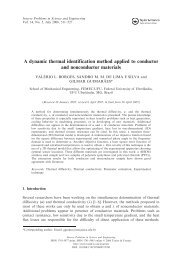
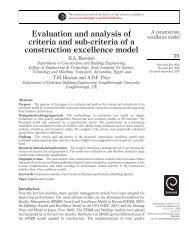
The thermal model of heat conduction and its regions for the<br />
imposition of the boundary conditions <strong>in</strong> three-dimensional <strong>coated</strong><br />
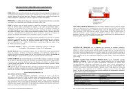
<strong>tools</strong> are presented <strong>in</strong> (Fig. 1). The geometry represented by Ω 1 is the<br />
Fig. 1. Coated cutt<strong>in</strong>g tool: <strong>in</strong>terface detail (a) and the flux region (b).
316 R.F. Brito et al. / International Communications <strong>in</strong> Heat and Mass Transfer 36 (2009) 314–321<br />
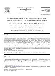
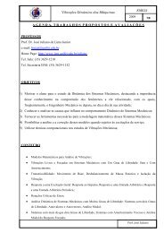
Fig. 2. Non-structured f<strong>in</strong>ite volume mesh (a), mesh detail (b), image of the flux area (c).<br />
coat<strong>in</strong>g solid of thickness e and Ω 2 is the cutt<strong>in</strong>g tool substrate of height<br />
H. C represents the <strong>in</strong>terface region between the coat<strong>in</strong>g and the<br />
substrate. Only one type of material was considered for the<br />
12.7 (mm)×12.7 (mm)×4.7 (mm) cutt<strong>in</strong>g tool, with 0.8 (mm) radius<br />
R and heat flux region S 2 with the approximate area of 1.424 (mm 2 ). The<br />
coat<strong>in</strong>g thickness values adopted were: e=0.010 (mm) and 0.001 (mm).<br />
The heat diffusion equation is subject to two types of boundary<br />
conditions: imposed heat flux <strong>in</strong> S 2 and constant convection <strong>in</strong> the<br />
rema<strong>in</strong><strong>in</strong>g regions of the cutt<strong>in</strong>g tool.<br />
The thermal parameters of the materials <strong>in</strong>vestigated, both the<br />
substrate and the tool coat<strong>in</strong>g, under ambient temperature were: K10<br />
tool: ρ=14,900 (kg m −3 ) [9], C p =200 (Jkg −1 K −1 )(valueadopted<strong>in</strong><br />
the present work), k=130 (W m −1 K −1 )at25(°C)[9]; diamond tool:<br />
ρ=3515(kgm −3 ) [10],C p =471(Jkg −1 K −1 ) [10],k=2000(Wm −1 K −1 )<br />
[10]; TiN coat<strong>in</strong>g: ρ=4650 (kg m −3 ) [4], C p =645 (J kg −1 K −1 ) [4],<br />
k=21(Wm −1 K −1 )at100(°C)[4];Al 2 O 3 coat<strong>in</strong>g: ρ=3780 (kg m −3 ) [4],<br />
C p =1079 (J kg −1 K −1 ) [4], k=28 (W m −1 K −1 ) [4].<br />
Fig. 2(a) and (b) shows one of the meshes used <strong>in</strong> the numerical<br />
simulation formed by hexahedral elements. (Fig. 2c) shows a typical<br />
contact area on the tool-chip <strong>in</strong>terface and the area used <strong>in</strong> the numerical<br />
simulation of the present work of approximately 1.424 (mm 2 ).<br />
The area for the follow<strong>in</strong>g cutt<strong>in</strong>g conditions was obta<strong>in</strong>ed from [11]:<br />
cutt<strong>in</strong>g speed of v c =209.23 (m/m<strong>in</strong>), feed rate of f =0.138 (mm/<br />
rot), and cutt<strong>in</strong>g depth of p=3.0 (mm).<br />
The follow<strong>in</strong>g hypotheses were considered <strong>in</strong> the present <strong>analysis</strong>:<br />
three-dimensional geometrical doma<strong>in</strong>; transient regime; absence of<br />
radiation models; constant thermal properties; perfect thermal contact<br />
and no thermal resistance contact between the coat<strong>in</strong>g layer and<br />
the substrate body; uniform and time-dependent boundary conditions<br />
of the heat flux q″(t).<br />
3. Numerical method<br />
For the solution of the cont<strong>in</strong>uity, momentum, and energy<br />
equations the Fluid Dynamics Calculus is employed by us<strong>in</strong>g the<br />
F<strong>in</strong>ite Volume Method (FVM) with Eulerian scheme for the spatial and<br />
temporal discretization of the physical doma<strong>in</strong> with a f<strong>in</strong>ite number of<br />
control volumes [12,13].<br />
Through this method, the control volume elements follow the<br />
Eulerian scheme with unstructured mesh [14]. Through this<br />
scheme, the transport equations may be <strong>in</strong>tegrated by apply<strong>in</strong>g<br />
Gauss Divergence Theorem, where the approximation of surface<br />
<strong>in</strong>tegral is done with two levels of approximation: first, the physical<br />
variables are <strong>in</strong>tegrated <strong>in</strong> one or more po<strong>in</strong>ts on the control<br />
volume faces; second, the <strong>in</strong>tegrat<strong>in</strong>g value <strong>in</strong> the centered faces is<br />
approximated <strong>in</strong> terms of nodal values. This approximation by the<br />
nodal value <strong>in</strong> the control volume centered faces represents the<br />
average physical quantity <strong>in</strong> all the control volume with second order<br />
accuracy [15].<br />
More details on the concepts <strong>in</strong>volved by the FVM may be found <strong>in</strong><br />
[14] where the discretization techniques, <strong>in</strong>tegral approximation<br />
techniques, convergence criteria, and calculus stability are<br />
explored.<br />
4. Numerical validation<br />
A study about the <strong>in</strong>fluence of mesh ref<strong>in</strong>ement on the temperature<br />
results was carried out. The <strong>analysis</strong> of the numerical mesh convergence<br />
was done by us<strong>in</strong>g the follow<strong>in</strong>g thermal properties of the ISO K10<br />
12.7 (mm)×12.7 (mm)×4.7 (mm) cemented carbide cutt<strong>in</strong>g tool<br />
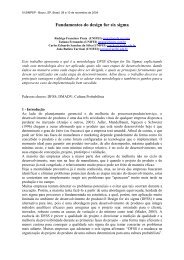
(Fig. 3a): k=43.1 (W m −1 K −1 ), C p =332.94 (J kg −1 K −1 ), and<br />
ρ=14,900 (kg m −3 ). The convergence test analyzed different dimension<br />
meshes, and their <strong>in</strong>fluence on the temperatures calculated by the<br />
numerical model was verified. In the majority of the studied cases, to<br />
obta<strong>in</strong> the results <strong>in</strong> this present work, the number of nodes utilized was<br />
501,768 and the number of hexahedrical elements was 481,500.<br />
The follow<strong>in</strong>g parameters were used <strong>in</strong> all mesh tests: time<br />
<strong>in</strong>terval of 0.22 (s), equal <strong>in</strong>itial and ambient temperature at 29.5 (°C),<br />
constant and equal heat transfer coefficient at 20 (W m −2 K − 1 ), total<br />
time of 110 (s), and area subjected to heat flux of 108.16 (mm 2 ).<br />
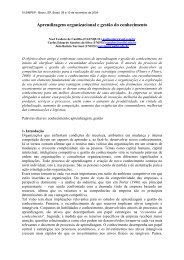
Fig. 3. Geometry (a) and Three-dimensional mesh (b).
R.F. Brito et al. / International Communications <strong>in</strong> Heat and Mass Transfer 36 (2009) 314–321<br />
317<br />
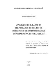
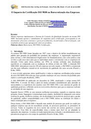
Fig. 4. Thermocouples T 1 (a) and T 2 (b): comparisons among the numerical and experimental temperatures [11] and the one calculated numerically <strong>in</strong> the present work.<br />
Accord<strong>in</strong>g to this study, it is clear that there was little difference<br />
as to the calculated temperature values. Moreover, the temperature<br />
residue among the meshes is practically negligible, with a deviation<br />
among them of less than 1% for all the simulated time range. In this<br />
numerical validation, we can conclude that a 16,038 nodal po<strong>in</strong>t<br />
mesh is already enough to obta<strong>in</strong> good accuracy and low cost<br />
computational time results. For a mesh developed with a greater<br />
number of elements, the temperature value barely varies with mesh<br />
ref<strong>in</strong>ement.<br />
The present work utilizes the experimental and numerical results<br />
from [11] <strong>in</strong> order to make a comparison with results obta<strong>in</strong>ed with the<br />
use of the software utilized for this present work. Carvalho et al.<br />
[11] carried out an experiment under controlled conditions <strong>in</strong> which<br />
an ISO K10 12.7 (mm)×12.7 (mm)×4.7 (mm) cemented carbide cutt<strong>in</strong>g<br />
tool was used (Fig. 3a). In [11] the author shows the experimental<br />
thermal flux delivered to the cutt<strong>in</strong>g tool and the temperatures<br />
measured by two thermocouples for time vary<strong>in</strong>g from t=0 to<br />
110 (s). The thermocouples were attached to the cutt<strong>in</strong>g tool by capacitor<br />
discharge (Fig. 3a) on the follow<strong>in</strong>g positions: thermocouple<br />
T 1 : x =4.3 (mm); y=3.5 (mm); z=4.7 (mm) and thermocouple T 2 :<br />
x=3.5 (mm); y=8.9 (mm); z=4.7 (mm).<br />
The data from experiment [11] are used as <strong>in</strong>put data for the<br />
numerical validation of the commercial package used <strong>in</strong> this present<br />
work. In this numerical model validation, the numerically simulated<br />
thermal properties of the cutt<strong>in</strong>g tool were: k=43.1 (W m −1 K − 1 ),<br />
C p =332.94 (J kg − 1 K − 1 ), and ρ=14,900 (kg m − 3 ). The coord<strong>in</strong>ates<br />
x, y, z of each thermocouple were measured for the comparison<br />
between the experimentally measured temperatures and those<br />
simulated by the commercial package.<br />
Fig. 3(a) and (b) shows the geometry and the mesh generated and<br />
used <strong>in</strong> the present work for the numerical validation. The numerical<br />
mesh was developed with the help of ANSYS ® ICEM-CFD, part of<br />
ANSYS ® CFX Academic Research software, v. 11. It can be verified from<br />
(Fig. 3b) that the ANSYS ® ICEM-CFD software generated a threedimensional<br />
structured mesh <strong>in</strong> which the regions <strong>in</strong> dark grey and<br />
light grey represent the cutt<strong>in</strong>g tool, and the light grey region is the<br />
area (Fig. 3b) subjected to the heat transfer rate obta<strong>in</strong>ed experimentally<br />
by Carvalho et al. [11]. Follow<strong>in</strong>g the study on the mesh<br />
<strong>in</strong>dependence, a three-dimensional mesh conta<strong>in</strong><strong>in</strong>g 15,548 hexahedral<br />
elements and 17,497 nodal po<strong>in</strong>ts was used. The light grey area is<br />
10.4 (mm)×10.4 (mm), on the xy-plane for z=0 (mm). Once the<br />
mesh is generated, the implementation process for the boundary and<br />
<strong>in</strong>itial conditions are started on ANSYS ® CFX-Pre. To solve the<br />
problem, the ANSYS ® CFX-Solver [16] is used. In the numerical test<br />
preparation, two temperature monitor<strong>in</strong>g po<strong>in</strong>ts were <strong>in</strong>serted<br />
correspond<strong>in</strong>g to the positions of thermocouples T 1 and T 2 attached<br />
to the tool dur<strong>in</strong>g the experiment carried out by Carvalho et al. [11].<br />
Fig. 4(a) and (b) shows a comparison between the temperatures<br />
obta<strong>in</strong>ed experimentally and numerically from thermocouples T 1 and<br />
T 2 by Carvalho et al. [11] and the temperatures obta<strong>in</strong>ed numerically <strong>in</strong><br />
this present work with the ANSYS ® CFX Academic Research software,<br />
v. 11. The largest and the smallest deviation found <strong>in</strong> relation to the<br />
experimental case carried out by Carvalho et al. [11] was respectively<br />
6.07% for thermocouple T 2 and −0.53% also for thermocouple T 2 . The<br />
largest and the smallest deviation found <strong>in</strong> relation to the numerical<br />
case performed by Carvalho et al. [11] was respectively −2.18% for<br />
thermocouple T 2 and 0.25% also for thermocouple T 2 .<br />
It was verified that, with the numerical simulations done <strong>in</strong> the<br />
present Test (Fig. 4), the highest temperature gradients on the cutt<strong>in</strong>g<br />
tool occurred for the time <strong>in</strong>stant of approximately 67 (s), reach<strong>in</strong>g<br />
temperature values of approximately 79 (°C). From <strong>in</strong>stant 63 (s), the<br />
heat flux starts a dropp<strong>in</strong>g process where temperature starts fall<strong>in</strong>g<br />
after approximately 4 (s). It may be observed that the dark grey region<br />
on the tool (Fig. 3b) is not <strong>in</strong> physical contact with any metal, except<br />
with the environment. This situation, at room temperature<br />
T ∞ =29.2 (°C) and with heat transfer coefficient h=20 (W m −2 K<br />
− 1 ) [3], considerably favored the heat transfer rate dissipation on the<br />
tool caus<strong>in</strong>g the temperature to fall from approximately 79 (°C) to<br />
71.6 (°C) at f<strong>in</strong>al <strong>in</strong>stant 110 (s).<br />
Follow<strong>in</strong>g the validation with the numerical and experimental data<br />
from [11], the thermal model and the numerical solution for the<br />
mach<strong>in</strong><strong>in</strong>g process proposed <strong>in</strong> the present work are concluded. Thus,<br />
the numerical models for TiN and Al 2 O 3 <strong>coated</strong> K10 and diamond<br />
cutt<strong>in</strong>g <strong>tools</strong> are implemented <strong>in</strong> the present work, vary<strong>in</strong>g the<br />
Table 1<br />
Numerical results obta<strong>in</strong>ed from the temperature values at <strong>in</strong>stant 63 (s)<br />
Case<br />
Coat<strong>in</strong>g<br />
(µm)<br />
Time-vary<strong>in</strong>g<br />
heat flux<br />
(W m − 2 )<br />
Temperature on<br />
chip-tool <strong>in</strong>terface<br />
T CT (°C)<br />
Temperature on<br />
coat<strong>in</strong>g-substrate<br />
<strong>in</strong>terface T CS (°C)<br />
1 1 q 1 ″(t) 86.56 86.38 0.19<br />
2 1 q 2 ″(t) 600.15 598.29 1.86<br />
3 10 q 1 ″(t) 87.12 86.30 0.82<br />
4 10 q 2 ″(t) 605.80 597.60 8.20<br />
5 1 q 2 ″(t) 790.25 789.75 0.50<br />
6 10 q 2 ″(t) 795.65 788.45 7.20<br />
7 1 q 2 ″(t) 599.71 599.34 0.37<br />
8 10 q 2 ″(t) 603.33 598.03 5.29<br />
9 1 q 2 ″(t) 790.05 789.75 0.30<br />
10 10 q 2 ″(t) 793.25 787.95 5.30<br />
Temperature<br />
difference<br />
T CT − T CS (°C)
318 R.F. Brito et al. / International Communications <strong>in</strong> Heat and Mass Transfer 36 (2009) 314–321<br />
Fig. 5. Temperature monitor<strong>in</strong>g po<strong>in</strong>ts located on and under the 10 (µm) TiN coat<strong>in</strong>g layer, us<strong>in</strong>g the ANSYS ® CFX-Pre, <strong>in</strong>cluded <strong>in</strong> the ANSYS ® CFX Academic Research software, v. 11.<br />
thickness and the heat flux value imposed on the cutt<strong>in</strong>g tool. The heat<br />
rate q(t) obta<strong>in</strong>ed experimentally by Carvalho et al. [11] and used as<br />
<strong>in</strong>put data for the numerical validation of the present work was used<br />
to obta<strong>in</strong> the results for this present work.<br />
The results obta<strong>in</strong>ed numerically <strong>in</strong> the thermal simulation of TiN<br />
and Al 2 O 3 <strong>coated</strong> K10 and diamond cutt<strong>in</strong>g <strong>tools</strong> are presented next. It<br />
is highlighted that the K10 <strong>tools</strong> used <strong>in</strong> this simulation possess<br />
different thermal conductivity from that used <strong>in</strong> item 4.<br />
5. Result <strong>analysis</strong><br />
In order to <strong>in</strong>vestigate the temperature distribution for a time<br />
<strong>in</strong>terval t, ten cases were selected. The ma<strong>in</strong> objective is to analyze the<br />
thermal <strong>in</strong>fluence of the heat flux and the thickness variation of<br />
<strong>coated</strong> cutt<strong>in</strong>g <strong>tools</strong>.<br />
(Table 1) shows temperature values obta<strong>in</strong>ed on the chip-tool and<br />
the coat<strong>in</strong>g-substrate <strong>in</strong>terfaces, at <strong>in</strong>stant 63 (s), calculated <strong>in</strong> the<br />
present work with the use of the ANSYS ® CFX Academic Research<br />
software, v. 11. Case 2 (TiN <strong>coated</strong> K10 substrate) and Case 9 (Al 2 O 3<br />
<strong>coated</strong> diamond substrate) presented the highest and the lowest<br />
calculated temperature difference for the 1 (µm) coat<strong>in</strong>g with heat<br />
flux q 2 ″(t). Case 4 (TiN <strong>coated</strong> K10 substrate) and Case 8 (Al 2 O 3 <strong>coated</strong><br />
K10 substrate) presented the highest and the lowest calculated<br />
temperature difference for the 10 (µm) coat<strong>in</strong>g with heat flux q 2 ″(t).<br />
(Fig. 5) shows the two temperature monitor<strong>in</strong>g po<strong>in</strong>ts dur<strong>in</strong>g<br />
the numerical simulations carried out <strong>in</strong> this present work. For the<br />
Fig. 6. Cases 1 to 4 – Influence of the heat flux variation on the temperature – TiN <strong>coated</strong> K10 substrate.
R.F. Brito et al. / International Communications <strong>in</strong> Heat and Mass Transfer 36 (2009) 314–321<br />
319<br />
coord<strong>in</strong>ates on the tool substrate-coat<strong>in</strong>g <strong>in</strong>terface: x=1.5 (mm),<br />
y=0.25 (mm), and z=10 (µm) and on the coat<strong>in</strong>g: x=1.5 (mm),<br />
y=0.25 (mm), and z=0 (mm).<br />
The heat rate q(t) (W) used <strong>in</strong> the present work was obta<strong>in</strong>ed from<br />
an experiment carried out by [11]. The heat flux q 1 ″(t) (Wm − 2 ) used<br />
<strong>in</strong> the present work was based <strong>in</strong> this experiment, however,<br />
consider<strong>in</strong>g a different contact area on the tool-chip <strong>in</strong>terface.<br />
In most of the simulated cases, the number of nodal po<strong>in</strong>ts was<br />
501,768 and the number of hexahedral elements was 481,500.<br />
(Figs. 6 and 7) show the simulation results with <strong>coated</strong> cutt<strong>in</strong>g<br />
<strong>tools</strong>. The <strong>in</strong>fluence of the heat flux (Fig. 6) and coat<strong>in</strong>g thickness<br />
variation (Fig. 7) on the temperature fields on the chip-tool coat<strong>in</strong>gsubstrate<br />
<strong>in</strong>terfaces can be verified <strong>in</strong> these figures. It can be observed<br />
that the coat<strong>in</strong>g did not <strong>in</strong>fluence the temperature reduction, result<strong>in</strong>g<br />
as a consequence <strong>in</strong>to a low thermal isolation. The greater temperature<br />
decrease happened <strong>in</strong> Case 04 (Fig. 6d and Table 1), where the<br />
temperature value decreased from 605.80 (°C) to 597.60 (°C), at<br />
<strong>in</strong>stant 63 (s), result<strong>in</strong>g <strong>in</strong> a decrease of 8.20 (°C).<br />
Fig. 7. Cases 5 to 10 – Influence of the coat<strong>in</strong>g thickness variation on the temperature.
320 R.F. Brito et al. / International Communications <strong>in</strong> Heat and Mass Transfer 36 (2009) 314–321<br />
Fig. 8(a), (b), and (c) shows top, bottom, and detailed views of the<br />
temperature fields at <strong>in</strong>stant 63 (s) for Case 4 with 10 (µm) TiN <strong>coated</strong><br />
K10.<br />
One of the contributions of this work is the development of a<br />
numerical methodology which permits the simulations of complex<br />
form geometries as well as the <strong>in</strong>clusion of a more realistic heat flux <strong>in</strong><br />
relation to the experimental case.<br />
The numerical methodology implemented, along with the use of<br />
commercial software and CAD <strong>tools</strong> may be applied <strong>in</strong> the simulation of<br />
heat transfer <strong>in</strong> complex geometry cutt<strong>in</strong>g <strong>tools</strong>. The heat flux region <strong>in</strong><br />
this work (Fig. 2b) was obta<strong>in</strong>ed from the area measured on the tool (Fig.<br />
2c) <strong>in</strong> the experiment carried out by Carvalho et al. [11]. Itmaybe<br />
observed from (Fig. 8) that the heat flux region has an area as close as<br />
possible to the experimental (Fig. 2c) and numerical areas used by the<br />
author <strong>in</strong> [11], where a simple rectangular numerical area was adopted.<br />
6. Conclusions<br />
The follow<strong>in</strong>g conclusions may be cited regard<strong>in</strong>g the numerical<br />
results obta<strong>in</strong>ed for the thermal model of heat transfer <strong>in</strong> <strong>coated</strong><br />
cutt<strong>in</strong>g <strong>tools</strong>:<br />
1) The studies carried out dur<strong>in</strong>g the execution of the work showed<br />
that for a uniform heat source vary<strong>in</strong>g <strong>in</strong> time, consider<strong>in</strong>g a<br />
constant contact surface on the chip-tool, the temperature on the<br />
tool may be slightly <strong>in</strong>fluenced by the coat<strong>in</strong>gs when the thermal<br />
properties of the coat<strong>in</strong>g are very different from those of the<br />
substrate, even for f<strong>in</strong>e 1 (µm) coat<strong>in</strong>g.<br />
2) By <strong>in</strong>creas<strong>in</strong>g ten times the heat flux imposed on the chip-tool<br />
<strong>in</strong>terface, the difference of the temperatures measured at the<br />
monitor<strong>in</strong>g po<strong>in</strong>ts showed a proportional <strong>in</strong>crease of approximately<br />
seventeen times.<br />
3) The coat<strong>in</strong>g deposited on the analyzed cemented carbide tool did<br />
not show satisfy<strong>in</strong>g results dur<strong>in</strong>g a cont<strong>in</strong>uous cutt<strong>in</strong>g process. A<br />
slight reduction <strong>in</strong> the heat flux was observed <strong>in</strong> the present work<br />
as <strong>in</strong> [4–8].<br />
4) There was no significant change on the heat flux penetrat<strong>in</strong>g the<br />
1 (µm) TiN <strong>coated</strong> K10.<br />
5) The present heat transfer <strong>analysis</strong> <strong>in</strong> <strong>coated</strong> cemented carbide<br />
cutt<strong>in</strong>g <strong>tools</strong>, us<strong>in</strong>g commercial computational <strong>tools</strong>, revealed<br />
promis<strong>in</strong>g features <strong>in</strong> the study of the tool life, cost reduction <strong>in</strong><br />
dry mach<strong>in</strong><strong>in</strong>g processes, reduction of the time spent on the study<br />
of thermal <strong>in</strong>fluence of coat<strong>in</strong>gs, and reduction of the number of<br />
experiments.<br />
6) A more detailed <strong>in</strong>vestigation is necessary <strong>in</strong> order to <strong>in</strong>clude other<br />
types of coat<strong>in</strong>g materials, their thickness, consider<strong>in</strong>g the<br />
<strong>in</strong>fluence of temperature variation on the thermal conductivity k<br />
and specific heat capacity C p .<br />
Acknowledgements<br />
The authors would like to thank CAPES, CNPq, and FAPEMIG for the<br />
f<strong>in</strong>ancial support granted for the present work, as well as the ESSS<br />
company for the technical support <strong>in</strong> use of the ANSYS ® CFX Academic<br />
Research software v. 11.<br />
Fig. 8. Top (a), bottom (b), and the heat flux surface (c) views of the temperature fields measured <strong>in</strong> (K), on the TiN <strong>coated</strong> K10 cutt<strong>in</strong>g tool for Case 4, at <strong>in</strong>stant t=63 (s).
R.F. Brito et al. / International Communications <strong>in</strong> Heat and Mass Transfer 36 (2009) 314–321<br />
321<br />
References<br />
[1] T.D. Marusich, C.J. Brand, J.D. Thiele, A methodology for simulation of chip<br />
breakage <strong>in</strong> turn<strong>in</strong>g processes us<strong>in</strong>g an orthogonal f<strong>in</strong>ite element model,<br />
Proceed<strong>in</strong>gs of the Fifth CIRP International Workshop on Model<strong>in</strong>g of Mach<strong>in</strong><strong>in</strong>g<br />
Operation, West Lafayette, USA, 2002, pp. 139–148.<br />
[2] W. Grzesik, A computational approach to evaluate temperature and heat partition<br />
<strong>in</strong> mach<strong>in</strong><strong>in</strong>g with multiplayer <strong>coated</strong> <strong>tools</strong>, Int. J. Mach. Tools Manuf. 43 (2003)<br />
1311–1317.<br />
[3] Y.C. Yen, A. Ja<strong>in</strong>, P. Chigurupati, W.T. Wu, T. Altan, Computer simulation of<br />
orthogonal cutt<strong>in</strong>g us<strong>in</strong>g a tool with multiple coat<strong>in</strong>gs”, Proceed<strong>in</strong>gs of the Sixth<br />
CIRP International Workshop on Model<strong>in</strong>g of Mach<strong>in</strong><strong>in</strong>g Operation, McMaster<br />
University, Canada, 2003, pp. 119–130.<br />
[4] Y.C. Yen, A. Ja<strong>in</strong>, P. Chigurupati, W.T. Wu, T. Altan, Computer simulation of<br />
orthogonal cutt<strong>in</strong>g us<strong>in</strong>g a tool with multiple coat<strong>in</strong>gs, Mach. Sci. Technol. 8 (2004)<br />
305–326.<br />
[5] J. Rech, A. Kusiak, J.L. Battaglia, Tribological and thermal functions of cutt<strong>in</strong>g tool<br />
coat<strong>in</strong>gs, Surf. Coat. Technol. 186 (2004) 364–371.<br />
[6] J. Rech, J.L. Battaglia, A. Moisan, <strong>Thermal</strong> <strong>in</strong>fluence of cutt<strong>in</strong>g tool coat<strong>in</strong>gs, J. Mater.<br />
Process. Technol. 159 (2005) 119–124.<br />
[7] A. Kusiak, J.L. Battaglia, J. Rech, Tool coat<strong>in</strong>gs <strong>in</strong>fluence on the heat transfer <strong>in</strong> the<br />
tool dur<strong>in</strong>g mach<strong>in</strong><strong>in</strong>g, Surf. Coat. Technol. 195 (2005) 29–40.<br />
[8] R.T. Coelho, E.G. Ng, M.A. Elbestawi, Tool wear when turn<strong>in</strong>g hardened AISI 4340<br />
with <strong>coated</strong> PCBN <strong>tools</strong> us<strong>in</strong>g f<strong>in</strong>ish<strong>in</strong>g cutt<strong>in</strong>g conditions, Int. J. Mach. Tools<br />
Manuf. 47 (2007) 263–272.<br />
[9] H. Engqvist, H. Hogberg, G.A. Botton, S. Ederyd, N. Axén, Tribofilm formation on<br />
cemented carbides <strong>in</strong> dry slid<strong>in</strong>g conformal contact, Wear 239 (2000) 219–228.<br />
[10] Matweb, 2008, http://www.matweb.com.<br />
[11] S.R. Carvalho, S.M.M. Lima e Silva, A.R. Machado, G. Guimarães, Temperature<br />
determ<strong>in</strong>ation at the chip-tool <strong>in</strong>terface us<strong>in</strong>g an <strong>in</strong>verse thermal model<br />
consider<strong>in</strong>g the tool and tool holder, J. Mater. Process. Technol. 179 (2006) 97–104.<br />
[12] H. Versteeg, W. Malalasekra, An Introduction to Computational Fluid Dynamics:<br />
the F<strong>in</strong>ite Volume Method, second ed., Prentice Hall, 2007, pp. 1–520.<br />
[13] R. Löhner, Applied Computational Fluid Dynamics Techniques: An Introduction<br />
Based on F<strong>in</strong>ite Element Methods, second ed., Wiley, 2008, pp. 1–544.<br />
[14] T. Barth, M. Ohlberger, F<strong>in</strong>ite volume methods: foundation and <strong>analysis</strong>,<br />
Encyclopedia of Computational Mechanics, Wiley, 2004, pp. 1–57.<br />
[15] C.T. Shaw, Us<strong>in</strong>g Computational Fluid Dynamics – An Introduction to the Practical<br />
Aspects of us<strong>in</strong>g CFD, Prentice Hall Publications, 1992.<br />
[16] ANSYS, Inc., ANSYS ® Academic research, release 11.0, Help system, coupled field<br />
<strong>analysis</strong> guide, 2008.