Untitled - HUBER
Untitled - HUBER
Untitled - HUBER

Create successful ePaper yourself
Turn your PDF publications into a flip-book with our unique Google optimized e-Paper software.
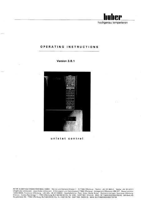
unistat control V3.8.1<br />
Contents<br />
1.<br />
V3.8.1 / 07.05<br />
Introduction .................................................................................................... 1<br />
2. General Information - Unistat Control ................................................................. 2<br />
2.1 Abbreviating keys............................................................................................ 3<br />
2.2 Display Information.......................................................................................... 3<br />
2.3 Fault .............................................................................................................. 3<br />
3. Physical Structure............................................................................................ 3<br />
3.1 Removing the Control Panel .............................................................................. 3<br />
3.2 remove unistat controller .................................................................................. 3<br />
3.3 Mounting the Unistat control............................................................................. 4<br />
3.4 Fuse change ................................................................................................... 4<br />
4. Control Panel .................................................................................................. 4<br />
4.1 Keypad .......................................................................................................... 4<br />
4.2 Actual value display......................................................................................... 4<br />
4.3 LCD window................................................................................................... 5<br />
4.4 Flow Diagram.................................................................................................. 5<br />
4.5 Signal Generator.............................................................................................. 5<br />
4.6 Remote Control ............................................................................................... 5<br />
5. Switch on....................................................................................................... 5<br />
6. Thermoregulation and Circulation....................................................................... 6<br />
6.1 Thermoregulation modes .................................................................................. 6<br />
6.1.1 Internal Control............................................................................................ 6<br />
6.1.2 External Control ........................................................................................... 7<br />
6.1.3 Other Temperature Control Methods............................................................... 7<br />
6.2 Switch on Circulation....................................................................................... 7<br />
6.3 Venting and Emptying ...................................................................................... 7<br />
6.4 No Fluid protection for Circulation Pump............................................................. 8<br />
6.5 Start Thermoregulation..................................................................................... 8<br />
6.6 Switching Off Thermoregulation ........................................................................ 9<br />
7. Altering Set Point ............................................................................................ 9<br />
7.1 Manual setting ................................................................................................ 9<br />
7.2 Set Point Ramp ............................................................................................... 9<br />
7.3 Thermoregulation Program .............................................................................. 10<br />
7.4 Change Set Point via Interface ........................................................................ 10<br />
7.4.1 „remote control„ ........................................................................................ 10<br />
7.4.2 TECON CONTROL ...................................................................................... 10<br />
7.4.3 4-20mA Analogue Interface (AIF)................................................................. 10<br />
7.5 Altering the set point via external control signal................................................. 10<br />
7.6 Set Point Tracking ......................................................................................... 10<br />
8. Safety Features............................................................................................. 10<br />
8.1 External Level Detector .................................................................................. 11<br />
8.2 Flow Detector ............................................................................................... 11<br />
8.3 Fault switches............................................................................................... 11<br />
8.4 Current Sensor / Power On Self-Test................................................................ 11<br />
8.5 Over Heating................................................................................................. 11<br />
8.6 Condensing Temperature Control..................................................................... 11<br />
8.7 Sensor Monitoring ......................................................................................... 12<br />
8.8 Circulation Safety Shut Down ......................................................................... 12
unistat control V3.8.1<br />
Contents<br />
8.9 Redundancy operation.................................................................................... 12<br />
8.10 Delta-T Monitoring ..................................................................................... 14<br />
9. Thermoregulation Programs ............................................................................ 14<br />
9.1 General ........................................................................................................ 14<br />
9.2 Program Descriptor ........................................................................................ 15<br />
9.3 Program Segments ........................................................................................ 15<br />
9.4 Approaching Starting Temperature................................................................... 16<br />
9.5 Running Tempering Programs.......................................................................... 16<br />
9.6 Ending A Thermoregulation Program ................................................................ 18<br />
9.7 Response to interruption of mains power .......................................................... 18<br />
Appendix A -- Program Directory.......................................................................... 19<br />
Program 0: Setting set point............................................................................... 19<br />
Program 1: Setting Of Minimum Set Point ............................................................ 19<br />
Program 2: Setting Of Maximum Set Point ........................................................... 20<br />
Program 3: Control Mode ................................................................................... 20<br />
Program 4: Second Set Point .............................................................................. 20<br />
Program 5: Mains Failure Automatic Function ....................................................... 21<br />
Program 6: POKO max....................................................................................... 21<br />
Program 7: POKO min........................................................................................ 21<br />
Program 8: POKO Programming .......................................................................... 21<br />
Program 9: ‘control parameters’.......................................................................... 23<br />
Program 10: Device Messages........................................................................... 24<br />
Program 11: Acknowledge Warning.................................................................... 25<br />
Program 12: Pt100 Correction (internal).............................................................. 25<br />
Program 13: Pt100 Correction (external) ............................................................. 25<br />
Program 14: Set Point Tracking ......................................................................... 25<br />
Program 16: Displaying Internal / External Actual Value in LCD .............................. 26<br />
Program 18: Delta–T–Limiter............................................................................. 26<br />
Program 19: Set Ramp Values ........................................................................... 26<br />
Program 20: Thermoregulation Program (TP) ....................................................... 28<br />
Program 21: Thermoregulation Program Parameters.............................................. 30<br />
Program 22: Thermoregulation Program Altering Run (during operation) .................. 30<br />
Program 23: Starting Thermoregulation Programs................................................. 30<br />
Program 24: Thermoregulation Processing Time ................................................... 31<br />
Program 25: Thermoregulation Program –Starting Date......................................... 31<br />
Program 26: Setting ‘TP track’ .......................................................................... 31<br />
Program 27: Time Base..................................................................................... 31<br />
Program 28: External Control-/release signal ........................................................ 32<br />
Program 29: Redundancy modes ........................................................................... 33<br />
Program 30: Setting date .................................................................................. 34<br />
Program 31: Setting The Time ........................................................................... 34<br />
Program 32: System Time Display...................................................................... 34<br />
Program 34: Air Venting Pause .......................................................................... 34<br />
Program 35: Compressor Automatic Controls ...................................................... 34<br />
Program 36: Activating Temperature for the HT................................................... 34<br />
Program 37: RS- Record Type............................................................................ 34<br />
Program 38: Time interval for RS Record ............................................................ 35<br />
Program 39: Separation Signs for RS Record Type 2 ............................................ 35<br />
Program 40: RS report on ................................................................................. 35<br />
Program 41: RS record off ................................................................................ 36<br />
Program 45: Watch–dog Function...................................................................... 36
unistat control V3.8.1<br />
Contents<br />
Program 46: Analogue interface – Control using current signal .............................. 37<br />
Program 47: Analogue Interface Monitoring........................................................... 37<br />
Program 49: Parameter limits.............................................................................. 37<br />
Program 51: Automation For The parameter ‘object mass’ ....................................... 37<br />
Program 52: Standard Parameter Set - Default..................................................... 38<br />
Program 55: Degassing..................................................................................... 40<br />
Program 56: ’Descaling’.................................................................................... 41<br />
Program 57: ‘Max cool power’ .......................................................................... 41<br />
Program 59: Compressor Clearance.................................................................... 41<br />
Program 68: Tempmove – flow temperature sensor.............................................. 41<br />
Program 69: Tempmove – reactor temperature sensor .......................................... 42<br />
Program 73: Advanced Control .......................................................................... 42<br />
Program 75: Fixed Cooling Power ...................................................................... 42<br />
Program 84: RS485 – Slave Address.................................................................. 42<br />
Program 85: Baud Rate for serial data transmission (RS232/485) ........................... 43<br />
Program 86: Selection RS232 ↔ RS485 ............................................................. 43<br />
Program 90: Language Selection ........................................................................ 43<br />
Program 93: Production number/serial number ..................................................... 43<br />
Program 94: Control Panel Identification ............................................................. 43<br />
Program 98: Version number ............................................................................. 43<br />
Program 106: Maximum Temperature Limit (for external Pt sensor control).............. 43<br />
Program 107: Minimum Temperature Limit (for external Pt sensor control) .............. 44<br />
Program 108: Maximum Temperature Limit (for internal Pt sensor control) .............. 44<br />
Program 109: Minimum Temperature Limit (for internal Pt sensor control) ............... 44<br />
Program 111: venting program ........................................................................... 44<br />
Program 116: Flow........................................................................................... 44<br />
Program 118: Delta-T Band Monitoring................................................................... 45<br />
Program 135: Analogue interface – calibrating of the AIF entry current.................... 45<br />
Program 136: Analogue Interface – calibrating of the AIF Exit Current Range ........... 46<br />
Program 137: Analogue Interface – Current/Temperature Relationship ..................... 46<br />
Program 138: Analogue interface – Assigning the exit signal .................................. 46<br />
Program 139: Analogue interface – Assignment Display......................................... 47<br />
Program 140: Analogue interface – Filter Constant................................................ 47<br />
Program 141: ‘Analogue Variable’ ....................................................................... 47<br />
Program 142: AIF-parameter-reset...................................................................... 47<br />
Program 143: „XL_CHARGE“ (UNISTAT XL only).................................................. 47<br />
Program 144: „XL-Power“ (UNISTAT XL only) ...................................................... 47<br />
Program 145: „XL – Vorhalt“ (UNISTAT XL only).................................................. 48<br />
Program 146: „XL – Starttemperaturdifferenz“ (UNISTAT XL only).......................... 48<br />
Program 147: „XL – Mode“ (UNISTAT XL only) .................................................... 48<br />
Program 148: „XL – Timer“ (UNISTAT XL only) .................................................... 48<br />
Program 149: „XL – Stoptemperaturdifferenz“ (UNISTAT XL only) .......................... 48<br />
Program 180: Heating Power Limiter ................................................................... 48<br />
Program 181: Cooling Power Limiter.................................................................... 48<br />
Appendix B -- Unit Messages .............................................................................. 49<br />
Appendix C -- PC/PLS data communication............................................................ 64<br />
Appendix D -- interface specification .................................................................... 65<br />
D.1. RS232 interface (on Plug Stv 12)................................................................. 66<br />
D.2. RS485 interface (on Plug Stv 12)................................................................. 66<br />
D.3. External Control Signal (‘release’, Plug Stv 5 at the unistat)............................. 66
unistat control V3.8.1<br />
Contents<br />
D.3.1 ‘OFF’........................................................................................................ 66<br />
D.3.2 ‘Pause / Stop’............................................................................................ 67<br />
D.3.2.1 A thermoregulation program is running: .................................................. 67<br />
D.3.2.2 Normal Thermoregulation:..................................................................... 67<br />
D.3.2.3 A control computer has taken over the control: ....................................... 67<br />
D.3.3 ‘Second Set Point Value’............................................................................. 67<br />
D.3.4 ‘Switch from Internal ↔External’ ................................................................. 67<br />
D.3.5 Analogue Port Tint ↔ Text.......................................................................... 67<br />
D.3.6 Stand by ................................................................................................... 67<br />
D.3.7 SP SWITCH............................................................................................... 68<br />
D.4. Potential (volt) Free Contact (POKO, plug connection Stv 4 at unistat).............. 68<br />
D.4.1 POKO ‘OFF’ .............................................................................................. 68<br />
D.4.2 POKO ‘actual value check’ .......................................................................... 68<br />
D.4.3 POKO ‘External Alarm’................................................................................ 68<br />
D.4.4 POKO ‘UNIPUMP/ PLS’ ............................................................................... 68<br />
D.4.5 POKO ‘TP spur [1]’..................................................................................... 69<br />
D.4.6 POKO ‘TP spur [2]’..................................................................................... 69<br />
D.4.7 POKO ‘Extern’ ........................................................................................... 69<br />
D.4.8 POKO ‘UNIPUMP with Echo’........................................................................ 69<br />
D.5. Analogue interface 4..20 mA....................................................................... 69<br />
D.6. Pt100 external........................................................................................... 70<br />
D.7. External level monitor ................................................................................. 71<br />
D.8. Plug Connection unistat control control unit........................................... 71<br />
D.9. Plug Connection unistat control unit ..................................................... 71<br />
Appendix E -- PP - command set for RS232 .......................................................... 72<br />
Appendix F -- LAI Command Set for RS485 .......................................................... 78
1. Introduction<br />
unistat control V3.8.1<br />
unistat control is the name for the electronic control system of the Huber unistats and<br />
Unichillers. It consists of the control electronics unit and a control panel (Picture 3), which<br />
can be used as a remote controller via an extension cable available as an optional extra.<br />
The following documentation enables quick familiarization with your unit:<br />
• The supplementary short version of the instructions together with the fold out page<br />
• These instructions<br />
• For reference and to get to know the valuable special functions, the appendix A-F at the<br />
back of these instructions.<br />
! To ensure safe use of the equipment these instructions should be read completely,<br />
at least once, prior to use.<br />
These instructions familiarise you with some new functions, which offers you a range of new<br />
properties:<br />
- Ease of control through prompts and clear display of important parameters.<br />
- Increasing operational safety due to constant monitoring of the control functions due to a<br />
control system which is independent of the electronic control system. Refer to the notes in<br />
paragraph „precautions„.<br />
LAI - The control unit offers a number of functions for the Laboratory Applications Interface<br />
software (Appendix C).<br />
- Calibrateable analogue interface<br />
- Serial interface RS232 or RS485 (selection optional)<br />
- Dry contact (just call it POKO) programmable for various functions.<br />
- Minimum and maximum set point can be pre set depending on the safety limits of the<br />
tempering liquid.<br />
- External control signal to trigger second set point other programmable functions.<br />
- Integrated controller for external tempering.<br />
- Continuous realization of the operating current principle for POKO and release signal.<br />
- Connection for external Pt100 sensor in 4-core arrangement (according to NAMUR<br />
recommendations)<br />
- Pt100 sensor calibration (Program 12 and 13)<br />
- Integrated programmer with calendar functions<br />
- 9 tempering programs with ca 270 segments can be stored<br />
- Tempering programs time and stable temperature programmable, repeat function.<br />
- External control signal and automatic mains failure function react with the programmer<br />
- Equipment shut-down is avoided, where low load operation is possible, by using different<br />
parameters.<br />
- Intelligent analyses of all sensor signals for assessment of machine status, with output of<br />
messages and warnings.<br />
- Automatic safety shut-down by major fault<br />
- Log of events for assessment of equipment performance. Important events will be shown<br />
with time and date. (Program 10).<br />
- fine tuning of the apparatus parameters for requirements of the automated application.<br />
Pre selection of heating or cooling capacity for the connection of external control circuits.<br />
(Program 44)<br />
- remote control and remote maintenance via PC interface possible (Appendix C)<br />
- As additional security installation you can use an adjustable level protection.<br />
Please take note of the information contained in „Safety Features„<br />
1
News From Software Version 3.4:<br />
unistat control V3.8.1<br />
• External Pt 100 can be used to either monitor or control.<br />
• Delta-T-control protects the external glass reactor from thermal shock. (Program 18)<br />
• Compressor automation: 3 states available „ON„, „OFF„, „AUTOMATIC„<br />
• In units with HT- coolers: The temperature at which the HT- cooler is switched on.<br />
(Program 36)<br />
• Additional POKO-Functions (Program 8).<br />
• Set point tracking/ Reactor lid thermoregulation (calorimetric) Program 14.<br />
• External control signal - additional functions (Program 28).<br />
• Analogue signal to set temperature instead of controller (Program 46).<br />
• Monitoring analogue signal (Program 47)<br />
• Selecting the temperature measurement source for control (Programs 68 und 69)<br />
• Heating/cooling power controlled via the digital Interface (Program 73).<br />
• Monitoring comparison of flow and reactor temperature (Programs 106 to 109).<br />
• Heating and cooling power limiting (Programs 180 and 181)<br />
2. General Information - Unistat Control<br />
The electronic unistat control used on the Huber unistats and Unichillers is universal<br />
throughout the range. It consists of two parts, the controller and control panel. Unistat<br />
control has an integrated cascade controller. Using an external Pt100 the application can be<br />
thermoregulated, wherever the sensor is placed. A level monitor can be installed for additional<br />
safety.<br />
The Unistat control is equipped with a non-volatile memory. The software used memorizes<br />
unit status data, which can be called up at a later date. An electronic clock makes a recording<br />
in chronological order possible. This makes it possible to activate the programmer at any<br />
selected date and time.<br />
The RS232 interface makes an event log of a process possible. The unit can be programmed<br />
so that the unistat control continuously sends values, unit status (status of the monitor, of<br />
potential free contacts, of the release signals) and the corresponding times and temperatures<br />
(can be transmitted with a resolution of 0.01K).<br />
Sensors have been installed to monitor and continuously analyze the unit. Temperatures,<br />
pressure, error conditions, electric voltages and currents are monitored. All actions are timed.<br />
The information obtained from the control unit are classified as follows:<br />
Messages inform, will be „blended in„ to monitor and record specific conditions (for example<br />
‘HEATLIMIT 50%‘).<br />
Warnings are stored and displayed to advise users of such conditions. Warnings must be<br />
acknowledged (program 11 Acknowledgement of warnings).<br />
Fault cause the mains cut off relay to isolate the circuits for the compressor, heating, pump<br />
and fans. This condition arises, if for example unreasonable high power consumption is<br />
measured for the current operating status. This condition will always be displayed. It is not<br />
reversible. This condition will be visually indicated by blinking in the actual value display and<br />
the LED’s in the flow diagram (Picture 1 see drawing at the last page).<br />
The controller is designed, so that specific settings will be locked during tempering. You get<br />
instructions via the LCD display. The changing of the minimum – maximum set points is only<br />
possible when the circulation is turned off. This avoids accidental adjustment of parameters.<br />
2
2.1 Abbreviating keys<br />
unistat control V3.8.1<br />
You often find the instruction in the text to press a key. The used abbreviation is always the<br />
„“ brackets. The instruction to press „0„ will look like this: <br />
Because of the danger of confusion the red key at the bottom of the controller (the 0-key)<br />
will be called in the instructions: <br />
is for the RAMP function, for ‘Set’ and so on.<br />
2.2 Display Information<br />
You can program the Unistat Control in one of three languages (German, English and French).<br />
Simple text that is understandable in all languages is displayed in one language.<br />
The display language is set using program 90.<br />
2.3 Fault<br />
Important occurrences are saved with date and hour in a long-term memory. With program 10<br />
and Appendix B incidents like Start/Stop of thermoregulation or any failure of unit can be<br />
interpreted.<br />
3. Physical Structure<br />
The control electronics of the unistat control is accommodated in a separate detachable<br />
housing. It is therefore possible to apply the valuable „Plug & Play“ philosophy which has<br />
been part of Huber equipment for many years. It is also possible to use it in the new<br />
generations of Unistats. Unistat control consists of two units: the electronic controller and<br />
the control panel placed in a recess in the housing.<br />
The control panel can be detached from the controller (a screw from above) and the<br />
electronic connection to the controller can be made with a special cable (Order No 6147).<br />
If the control panel is to be used via a cable connection, reference should be made to the<br />
paragraph ‘Remote Control’.<br />
3.1 Removing the Control Panel<br />
1) Turn off tempering and circulation by pressing key, turn off mains switch on<br />
unit.<br />
Switch off main switch on chillers<br />
2) Unplug from mains.<br />
3) Remove cover from fixing screw (picture 2 see drawing at the last page).<br />
For chillers: Remove the cover of plug connector (3 screws) directly behind control<br />
panel.<br />
4) Loosen M3 screw and remove.<br />
5) Tip control panel forward until mounting recess is released (ca 1 cm). Carefully pull the<br />
control panel up and out of its recess.<br />
3.2 remove unistat controller<br />
1) Follow all steps as explained in ‘remove control panel’.<br />
2) Loosen screw ‘fixing unistat controller’ (picture 2 see drawing at the last page)<br />
3) The housing is still connected to the unit via a plug connector.<br />
4) Pull housing vertically up.<br />
3
3.3 Mounting the Unistat control<br />
unistat control V3.8.1<br />
1) Check for proper pin alignment.<br />
2) Slide control box vertically down over the guide pins and fix into place with the screw.<br />
3.4 Fuse change<br />
1) Follow all steps as explained in ‘remove unistat controller’.<br />
2) Two fuses are placed in the back of the control housing (picture 4 see drawing at the<br />
last page)<br />
F1 (2A slow) circulation pump and fan<br />
F2 (0.2A slow) control electronics<br />
4. Control Panel<br />
Important information must be read carefully:<br />
The control panel is the central point for all information coming from and going to the<br />
thermostats, as well as for analogue control by the user, to the laboratory automation<br />
equipment, to the PC etc. Should the overview of the programmed functions be lost a<br />
parameter rest can be made using Program 52, which reverses everything back into initial<br />
status (factory setting).<br />
4.1 Keypad<br />
To comply with ingress protection requirements, the keypad and the display are covered with<br />
a protective film.<br />
The unit is equipped with seven rows of three keys. There are three keys in the bottom row<br />
to start the circulation pump and the thermoregulation (both green) and also the red 0-key.<br />
‘0’ is for ‘OFF’ (picture 1 see drawing at the last page). The row of keys above is for the<br />
programming of the unistat or Unichiller (function selection):<br />
Key < Set > starts the program selection<br />
Key < Ent > acknowledges the entered value<br />
Key < Esc > prematurely (without accepting the input) exits the program<br />
Ramp Function<br />
One row above are keys for the setting of the tempering program and to directly input the set<br />
values:<br />
< Ramp > a ramp in a segment or a set point ramp<br />
< Temp > desired end temperature of a segment or a set point temperature<br />
< Time > duration of a segment, or a check of the system time<br />
4.2 Actual value display<br />
See Program 3.<br />
The most striking and most important display is the green LED display indicating the actual<br />
value. Depending on the tempering mode the display shows a, 5 digit, temperature display of<br />
the internal or the external sensor (see picture 1 see drawing at the last page). A flashing<br />
display of the actual value indicates fault status.<br />
4
4.3 LCD window<br />
unistat control V3.8.1<br />
A numerical is not sufficient for this sophisticated unit. The illuminated LCD window contains<br />
the alpha/numeric display in two rows with 16 digits each row (picture 1 see drawing at the<br />
last page).<br />
4.4 Flow Diagram<br />
The flow diagram is situated in the top third of the control panel (picture 1 see drawing at the<br />
last page). It is the status display path of the thermostat liquid. The four green dots at the<br />
start, before and after the pump (LED 3,4,5,6 see drawing at the last page) are illuminated, if<br />
the pump is turned on. The yellow dot (Led 7), when the heater is turned on and the green<br />
dot bottom right (LED 8), when the cooling is on. Additionally the green dot (LED 10) shows<br />
the power is on to the compressor, above the green dot (LED 9) is for an activated HT chiller<br />
(if present). One of the two red dots, connected by a dotted line shows if internally (jacket<br />
thermoregulation, LED 2) or externally (controller / reactor thermoregulation, LED 1 in reactor<br />
symbol) controlled.<br />
4.5 Signal Generator<br />
The signal generator provides information of events that occur suddenly or due to a faulty<br />
operation. Characteristic sounds are for certain events. The signal is not loud enough to be<br />
used as a warning signal. The POKO (program 8) together with suitable externally acoustic<br />
device should be used for that purpose.<br />
4.6 Remote Control<br />
The control panel can, following the steps of ‘removal of control panel’ be removed from the<br />
unistat control and used via a cable connection. If the electric connection is interrupted, the<br />
unistat control will stop thermoregulation and an emergency shut down will result.<br />
Please switch off the thermostat in this case.<br />
5. Switch on<br />
After switching on the main switch, the control panel and the controller carry out an<br />
extensive self-diagnosis. A message will be displayed if anything unusual occurs.<br />
The important status information will be displayed as message. The following message could,<br />
for example, appear:<br />
The controller has been programmed for automatic switching on after the restoration of<br />
power, after failure of the main power supply.<br />
Automode: ein<br />
or<br />
Automode: on<br />
5<br />
or<br />
Automode: active<br />
Attention: one of these messages will appear depending on the language chosen (set with<br />
program 90).<br />
If you activate a function via the ‘external control signal’ (program 28), the following<br />
message will be displayed:<br />
Zweiter Sollwert<br />
or<br />
Second Set point<br />
or<br />
Consign 2
unistat control V3.8.1<br />
A tempering program can be initiated via the calendar. If a start date for Program 2 has been<br />
entered (Program 23), the following will be displayed when the equipment is switched on.<br />
Program start: 2<br />
27.11.01 5:15<br />
or<br />
Program start: 2<br />
27.11.01 5:15<br />
6<br />
or<br />
Départ progr.: 2<br />
27.11.01 5:15<br />
Also you will be informed of the status of the calendar and the clock. Information about the<br />
status (including date and time) of the unistat control can be recalled with the corresponding<br />
program functions at a later date.<br />
Generally the following applies: You will be informed if the general sequence is not disturbed,<br />
this information can be retrieved as an event log for a period of time.<br />
When the unit is ready to start, the following information is displayed:<br />
257 int 300max<br />
257.5°C -40min<br />
All temperatures are displayed in °C.<br />
For this representation it means:<br />
‘257.5 °C’ the set point in °C<br />
‘257 int’ the actual value, in this case measured with internal temperature sensor<br />
‘300max’ the maximum permitted set point<br />
‘-40min’ the minimal permitted set point<br />
Should there be an irregularity in the results of the initial self diagnosis, the following codes<br />
could appear together and are only possible after the mains switch on: 51/5, 51/29, 51/30,<br />
51/31, 51/35. Please check Appendix B for the meaning of these and other device messages.<br />
If it is attempted to start the circulation or thermoregulation immediately after, the circulation<br />
will not begin because the self-diagnoses has not been completed. During this the four green<br />
pump lights (LED 3, 4, 5, 6 see drawing at the last page) are flashing, these signal the call for<br />
circulation.<br />
6. Thermoregulation and Circulation<br />
6.1 Thermoregulation modes<br />
Program 3 can be used to switch between internal and external thermoregulation modes.<br />
6.1.1 Internal Control<br />
The internal thermoregulation uses a control loop to control the temperature at the internal<br />
Pt100-temperature sensor. This is called the „flow sensor„. It is built into the unit and is<br />
located near the discharge of the thermofluid (flow). Program 9 can be used to alter the<br />
parameters of the proportional–integral-controllers (PI-controller)<br />
Certain thermoregulation duties require different control methods to achieve best results.<br />
Set points can be supplied from various sources. Program 68 allows various alternatives.
6.1.2 External Control<br />
unistat control V3.8.1<br />
External thermoregulation uses an external Pt100-temperature sensor (Order No 6205 or<br />
6064) in conjunction with a cascade controller. The internal sensor in the flow is included in<br />
the control. This external method is used for the thermoregulation of jacketed systems.<br />
Certain thermoregulation duties require different control methods to achieve best results.<br />
Set points can be supplied from various sources. Program 69 allows various alternatives.<br />
Please pay attention to the following information. If the external sensors have not been<br />
supplied by Huber:<br />
- The external sensor must have a screened connection cable. This is to protect from static<br />
discharge and for ensuring accurate measurements.<br />
- If the sensor housing is made of metal, earth loops must be avoided.<br />
- The cable should not be unreasonably long.<br />
- Make sure the fixing of the external sensor at the place of measurement is satisfactory and<br />
a satisfactory heat transfer will be achieved.<br />
- The sensor must be well insulated to the screening or to the protective ground (R>20MΩ)<br />
6.1.3 Other Temperature Control Methods<br />
Certain, particularly specialized thermoregulation applications, it can be an advantage to<br />
bypass the integral temperature controller and control temperatures using different<br />
algorithms. Programs 73 and 75 are valuable tools for this purpose.<br />
6.2 Switch on Circulation<br />
To switch on circulation use the green key < I >(bottom left on control panel).<br />
The separate switch for the pump is particularly useful to vent the system.<br />
This could be the reason why the flow sensor has not been activated. If the flow detector is<br />
not activated, the following message will appear.<br />
kein Umwälzdruck<br />
or<br />
no flow<br />
7<br />
or<br />
Aucun débit!<br />
If the unit has been filled it is important for safe functioning that the equipment been<br />
completely vented. Please read the information in the instructions for the UNISTAT models<br />
carefully.<br />
6.3 Venting and Emptying<br />
Venting of the unit can be achieved using intermittent pump operation. The gas can separate<br />
better during the pause phase and will be pushed out during pumping.<br />
The venting program, intermittent pumping is achieved by pressing the pump key (
unistat control V3.8.1<br />
Make sure that all possible isolation valves in the liquid circuit are open. Information about<br />
valves and the setting of these can be found in the corresponding instructions of the unistat<br />
model. Attention should be given to the following connections when using a unistat with an<br />
HT slider. The slide control can shut off the HT chiller or the evaporator, depending on the<br />
operating status. It is helpful for the venting if all slide control positions are opened to vent all<br />
components.<br />
The following procedures are suggested for emptying:<br />
1. Fluid temperature should be near room temperature. If you are using a viscous thermofluid<br />
at room temperature, it should be a bit warmer.<br />
2. Set ‘venting’ (press circulation key twice alternatively activate program 111)<br />
3. Drain the liquid<br />
4. Switch of the venting program.<br />
Attention: If the flow temperature is near room temperature after switch on, set the HT slide<br />
controls in a position in which no component is isolated.<br />
If a large external system or a viscous thermofluid is being used, the vent pause time might<br />
have to be extended (see program 34). To control circulation pressure: see program 116.<br />
6.4 No Fluid protection for Circulation Pump<br />
The circulation pumps are not to be used without a working fluid. To prevent damage<br />
resulting from this, there is a no fluid protection system for the circulation pump. If the<br />
condition ‘pump pressure ok’ does not appear within a few seconds after switching on, the<br />
pump shuts down automatically. The message ‘no fluid protection has been activated’<br />
(60/45) is stored (see program 10 and paragraph ‘Safety precautions’). You can restart the<br />
pump using the circulation key , without having to switch off the system.<br />
The following information will appear on the LCD display:<br />
Pumpe trocken?<br />
Or<br />
Pump is dry?<br />
8<br />
Or<br />
Pompe sèche?<br />
This mechanism will remain activated until the status ‘pump pressure ok„ is sensed for the<br />
first time. If the pump pressure falls due to insufficient venting it is assumed that there is<br />
enough liquid present in the pump.<br />
The above message ‘Pump is dry?’ is acknowledged with . If you restart with the<br />
circulation key , the acknowledgement is not necessary. To control circulation<br />
pressure: see program 116.<br />
6.5 Start Thermoregulation<br />
The thermoregulation is started by pressing the key . The circulation is switched on.<br />
The message will be displayed once the correct circulation pressure has built up.<br />
Pumpentest<br />
in Ordnung<br />
or<br />
Check Pump<br />
OK<br />
Or<br />
Test Pompe<br />
En ordre<br />
The message ‘pump test’ is displayed again, if the circulation pressure does not build up<br />
thermoregulation is not possible.
unistat control V3.8.1<br />
If the flow detector is signaling circulation pressure although the pump has not started<br />
(probably due to a static column of thermofluid), the following<br />
message will appear:<br />
Druck ohne Pumpe<br />
or<br />
Pressure Failure<br />
9<br />
Or<br />
Press.saug pomp!<br />
The circulation pressure is constantly monitored while tempering is in operation.<br />
If the pressure should fall, the tempering will be switched off and the message ‘fault’ is<br />
displayed (see unit message 41/x in Appendix B). It is only possible to restart<br />
thermoregulation after turning the power off and back on. If this occurs during heating please<br />
consult program 55.<br />
In some models the chiller can be locked out due to a release signal not being present,<br />
especially after turning power back on. The corresponding message in displayed until<br />
clearance is given. The message informs that the minimum oil temperature is not reached yet<br />
inside the compressor and that it cannot be restarted. (see instructions of the unistat model)<br />
It is important that the compressor clearance being explained here is not confused with the<br />
external release signal, which is explained in Appendix D.<br />
Kühlma. Gesperrt<br />
or<br />
6.6 Switching Off Thermoregulation<br />
No Compr Clrance<br />
or<br />
Pause compress.<br />
To turn off the unit, press the key first. After that the controller can go back to the<br />
standby status. The circulation will stay on a few seconds to avoid heat build up, if the<br />
heating was in operation a short time before shut down. This can be stopped prematurely if<br />
the key is pressed again. The key should be used to protect the unit.<br />
The mains switch used only after the pump and the compressor have been switched off.<br />
7. Altering Set Point<br />
This paragraph introduces different methods of altering the set point and therefore the mode<br />
of thermoregulation.<br />
7.1 Manual setting<br />
See program 4 and 28, also Appendix C.<br />
The set point can be set by setting program 0 ( ) or with Hotkey<br />
. Reference should be made to the set point limits, which are values of the<br />
minimum and maximum set points. These are boundaries of the maximum and minimum set<br />
points allowed for this unit and are set by using programs 1 and 2.<br />
7.2 Set Point Ramp<br />
A ramp can be programmed, in place of a step change. This function is accessed by pressing<br />
key , or using program 19. The set point is set using the set point program 0, is<br />
depending on the selected mode of control (see program 3) and the internal and external<br />
Pt100 temperature sensor.<br />
A full description of this function is contained in the program directory (Appendix A) under<br />
program 19.
7.3 Thermoregulation Program<br />
unistat control V3.8.1<br />
Programs 20, 21, 22, 23 can be used to produce a tempering program (program 20), produce<br />
certain attributes (program 21), and start up (program 23).<br />
The process of a thermoregulation program can be altered using program 22.<br />
Consideration should be given to programmes 24, 25, 27 (see Appendix A).<br />
7.4 Change Set Point via Interface<br />
7.4.1 „remote control„<br />
The possibilities for PC control via the interface are described in Appendix C.<br />
7.4.2 TECON CONTROL<br />
This mode of operation uses the properties of the TECON software (see Huber Catalogue).<br />
Please call the service Hotline for more information. (+49 781 9603 244)<br />
7.4.3 4-20mA Analogue Interface (AIF)<br />
The analogue interface is explained in Appendix D. The programs 137, 138, 139, 140 and 46<br />
are necessary for the use of AIF. Calibration is possible with programs 135/136.<br />
7.5 Altering the set point via external control signal<br />
The possibility of changing the set point via the external control signal is explained in<br />
Appendix D and program 28. The change over to the’2nd Set point ‘ is explained in<br />
program 4.<br />
7.6 Set Point Tracking<br />
The set point of the thermostat can be linked to the temperature of a measuring point using<br />
the external Pt100 temperature sensor and program 14. In this mode of operation, the<br />
thermostat follows a temperature to be supplied by another system. The calorimetric<br />
measurements can be used for lid thermoregulation (see program 14).<br />
8. Safety Features<br />
There are a number of safety features installed in unistats or Unichillers, which control the<br />
correct function and maintain the parameters, so that the process is safe.<br />
This can be important if the process is left unattended. This function can be important for<br />
over heat protection and level monitoring in external baths<br />
! Check the functioning of all safety features in short regular intervals.<br />
Information about checking the over heat protection is contained in the instructions for the<br />
unit.<br />
10
8.1 External Level Detector<br />
unistat control V3.8.1<br />
The level detector is installed in the open bath, to be thermoregulated. As soon as the level<br />
decreases significantly a dangerous condition exists (a leak?). The level detector connected to<br />
the unistat control passes this on and the unit will be switched off.<br />
For exact description see Appendix D.<br />
8.2 Flow Detector<br />
The flow detector monitors the circulation. If the circulation pressure falls during<br />
thermoregulation<br />
it will release an emergency shut down. (See message 41/X in Appendix B and program 55).<br />
8.3 Fault switches<br />
Depending on the UNISTAT model various sensors will be analysed. Messages inform about<br />
status (see program 10).<br />
8.4 Current Sensor / Power On Self-Test<br />
The current sensor is an important device especially for testing the functions of contactors,<br />
relays and heaters.<br />
By energising such components their function can be evaluated in comparison with the<br />
measured power input.<br />
8.5 Over Heating<br />
Every UNISTAT model is equipped with over heat protection, which operates independently<br />
form the unistat control. Only requires one sensor register excess temperature and the<br />
heating will be switched off immediately. A more comprehensive description is contained in<br />
the operating manual for the particular thermostat.<br />
Chillers without heaters do not have over heat protection.<br />
! The over heat protection should be triggered regularly, by setting the over heat<br />
protection set point temperature just above the present set point and then heat a little.<br />
Only a fully operational over heat protector will help to avoid damage!<br />
8.6 Condensing Temperature Control<br />
During thermoregulation the condensing temperature of the unit is constantly monitored.<br />
When the maximum value is reached the cooling power of the unit will be reduced, reduces<br />
the condenser heat rejection. This condition will be displayed as a message after a few<br />
seconds. The warning will remain, until it is acknowledged (see program 11, „acknowledge<br />
warning„).<br />
Kondens.Temp.!<br />
or<br />
Condens.Temp.!<br />
11<br />
or<br />
T°C condenseur
unistat control V3.8.1<br />
The condensing temperature can rise up to the maximum point, if the cooling power is very<br />
high and the cooling of the condenser is not adequate.<br />
Air-cooled units- an increased ambient temperature and/or dust on the condenser fins can be<br />
a cause. The sucking in of paper can be a possible cause.<br />
Water-cooled units- it is possible that the cooling water pressure is too low and /or the<br />
cooling water temperature too high.<br />
8.7 Sensor Monitoring<br />
The tempering will be stopped as soon as the status ‘sensor defect’ appears during tempering<br />
and the message 46/x will be recorded. (See Appendix B)<br />
8.8 Circulation Safety Shut Down<br />
During circulation only, the circulation will be shut down if the flow temperature exceeds the<br />
maximum set point of 10K. This is to avoid uncontrolled heating due to heat being introduced<br />
due to the circulation pump. (See unit message 49/x in Appendix B). The machine will switch<br />
off if the flow indicator has not registered any pump pressure for 20 min.<br />
In this case no message will be displayed.<br />
8.9 Redundancy operation<br />
A thermoregulation process can be continued despite a sudden loss of the master thermostat<br />
through the operation of a “cold” redundancy. For this, two thermostats are involved in the<br />
process. One thermostat, the “Redu Master” takes over the thermoregulation.<br />
While, the second thermostat, the “Redu slave”, stays in standby (switched on without<br />
thermoregulation and without circulation). In case of a disturbance of the “Redu Master” the<br />
“Redu slave” will switch on and takes over. This function is possible through a conjunction of<br />
the thermostats signals. The POKO signal of the “Redu Master” and the signal at the level<br />
connector of the “Redu slave” are being used for this purpose. The Redu master’s O.K. status<br />
corresponds to the POKO relay being energised (OK-energised principle).<br />
A cable (# 6589 ‘heat carrier unit’) connects the POKO of the “Redu Master” to the ‘Level’ of<br />
the “Redu slave”. This cable gives no return signal to the “Redu Master” so it cannot not<br />
know that the “Redu slave” is connected!<br />
The “Redu slave”, e g the unit which is held redundant, can distinguish the following<br />
conditions:<br />
1. “Redu slave” is not activated and the cable is not connected – this is the normal<br />
operating condition.<br />
2. “Redu slave” is not activated and the cable is connected – the equipment goes to error<br />
‘Level’ 42/1 or 42/x depending on the master unit’s POKO condition. A Level error is<br />
recognized.<br />
3. “Redu slave” is activated and the cable is not connected – the equipment deactivates<br />
its POKO and gives a signal to the display “REDU: Connect?” and to the signal<br />
generator. The slave cannot go to redundancy but does not go to error and keeps its<br />
actual operating mode.<br />
4. “Redu slave” is activated and the cable is connected – the “master” unit has an active<br />
POKO: this is the redundancy standby operation mode.<br />
12
unistat control V3.8.1<br />
5. “Redu slave” is activated and the cable is connected – the “master” unit has an<br />
active POKO: the slave thermoregulates with the preset parameters.<br />
The operation modes “Redu slave” and “Redu Master” are alternately displayed on the<br />
second line of the units display. The operation mode POKO master/POKO slave is set in<br />
programme 29 (Redundancy Modes). The “Redu Slave” starts to thermoregulate when the<br />
POKO of the “Redu Master” becomes inactive.<br />
This is the case when:<br />
1. The “Redu Master” is unpowered.<br />
2. The “Redu Master” is not ready yet after starting the equipment.<br />
3. The “Redu Master” goes to error<br />
Behaviour of the “Redu Slave” after activation: Once activated the “Redu slave” can only be<br />
deactivated manually via the keyboard. The mode “Redu Slave” has to be terminated through<br />
programme 29. The thermoregulation continues but can be terminated with the off key.<br />
Effect on the float switch: the same socket is used for both tasks. For this reason, the float<br />
switch is automatically cut off if the “Redu Slave” mode is activated. If the “Redu Slave”<br />
mode is deactivated and the equipment starts with the connected “Redu cable”, an error<br />
message “level error” will be displayed.<br />
Please note: using a second equipment to enhance the security of the installation is a<br />
complex process. The above mentioned functionality is helpful but never the less; it will not<br />
reach the target by itself. For example investigation of the behaviour of the fluid circuit and if<br />
the need of swing-type check valves or the set point on which the slave has to operate and<br />
which procedure will ensure that the slave is really going to be active in an emergency etc…;<br />
still has to be done.<br />
Important note: Please regularly make sure of the correct function of the redundancy<br />
operation before every thermoregulation process.<br />
13
8.10 Delta-T Monitoring<br />
unistat control V3.8.1<br />
Monitors are mechanisms made to protect the application or the process. Limit values are<br />
given to the monitor. If the limit value is reached, an action is carried out. The Delta-T<br />
monitor is independent of the temperature controller. Accordingly the Delta-T monitor reacts,<br />
if the delta-T limit value is reached with heating or cooling.<br />
The temperature difference between the flow and the process temperature in the “external “<br />
tempering mode (ref. to program 3) is controlled. With program 118 the action as well as the<br />
limit value can be given. The default setting of the Delta-T monitor is given such that the limit<br />
value in the normal operation cannot be reached.<br />
9. Thermoregulation Programs<br />
9.1 General<br />
Unseat control is equipped with a programmer for the automated start and run of the<br />
thermoregulation programs. The connection of the programmer and controller makes a “fine<br />
tuning” of the unistat control possible.<br />
This refers to the programmable start time (program 23), the mains failure automation<br />
(program 5), the signalling via the potential free contact when the set temperature band is<br />
exceeded, the possibility to activate the POKO during a step of the tempering program<br />
(program 8) and the connection of an ‘external control signal’.<br />
14
unistat control V3.8.1<br />
Nine tempering programs with 30 program segments each are available.<br />
Each tempering program fundamentally consists of the program descriptor and up to<br />
30 program segments. The following settings prevailing at the start of processing a<br />
thermoregulation program will be adopted:<br />
Tempering method (internal or external),<br />
Minimum and maximum set points,<br />
Inclusion of external control signals,<br />
Use of potential free contact,<br />
Use of automatic response to main power failure.<br />
9.2 Program Descriptor<br />
When a tempering process is planned there is a particular path it has to follow the program is<br />
then set to follow this path exactly. The temperature ramps and temperature plateaux are<br />
only part of an automated process. Additionally the following data is required for the program<br />
descriptor at the start of the thermoregulation program. (See program 21).<br />
Start time for the thermoregulation program:<br />
The program start can take place immediately, or whenever you want. The setting for the<br />
start temperature for the first segment takes place in the program descriptor.<br />
A chosen ramp will start from the actual value to the starting temperature. If full power is<br />
required, a high value, for example 20 K/min, has to be set.<br />
Time or temperature stability for the tempering program:<br />
The rule for every program segment is:<br />
If the temperature at the end of the segment is to be checked the ‘temperature stability’<br />
function should be selected. The next program segment will get started, when the actual<br />
value reaches the end temperature of the program segment with fixed accuracy (+/- 1K).<br />
If on completion of the segment time the actual temperature is not to be checked, the time<br />
stable option should be selected.<br />
If you work the tempering program with length ‘0’, details of the starting temperature,<br />
starting ramp, or if it the temperature stable option will be requested. The programmer can<br />
repeat the program segments.<br />
9.3 Program Segments<br />
Each program segment contains two values: The segment end temperature and the duration<br />
of the segment. The starting temperature of the segment results automatically form the end<br />
temperature of the previous segment. The duration of the segment is reduced constantly<br />
during the program run. The next set point is therefore determined from the difference of the<br />
end temperature and the actual value. At the end of a segment it will be checked, if<br />
‘temperature stability’ (See 9.2) has been requested the end temperature is to be reached<br />
with +/- 1K accuracy. If maintenance steps are necessary, the program run time of the<br />
program is extended. The waiting time in the actual segment will be displayed as tw in the<br />
LCD display.<br />
15
9.4 Approaching Starting Temperature<br />
unistat control V3.8.1<br />
At the time of starting the first ramp characteristics and the actual temperature are known –<br />
provided the circulation has already started. At this the point the time is calculated, that is<br />
needed to achieve the starting temperature for the first ramp. The time for this temperature<br />
change will be determined automatically. After each time period the next set point is given to<br />
the controller. Once the calculated time has passed, the temperature is checked, if the actual<br />
value achieved corresponds with the starting temperature at the required accuracy. (+/-1K )<br />
If this is the case the first thermoregulation program segment will start. Otherwise the<br />
tempering will continue until the starting temperature is reached.<br />
In the event of mains failure:<br />
If the mains failure automatic feature was not activated the Unistat goes in to stand by,<br />
otherwise the start temperature will be achieved with the given gradient.<br />
9.5 Running Tempering Programs<br />
You will be informed during the whole run of the heating program via the LCD display.<br />
Immediately after the start (program 23) the following message might be displayed:<br />
or<br />
Startrampe!<br />
Nicht o.k.!<br />
Fehler: End-TMP<br />
Segment: 3<br />
or<br />
or<br />
Going Startramp<br />
Not OK!<br />
FAIL: End-TMP<br />
Segment: 3<br />
16<br />
or<br />
or<br />
T°C de départ<br />
incorrect(e)<br />
err. temp finale<br />
Segment: 3<br />
These messages let you know about conflicts between start temperature or end temperature<br />
(in segment 3) and the limits given by the minimum and maximum set points. After this has<br />
been corrected the same message can be repeated in a later segment. If this message comes<br />
up in segment 25, although your program only runs for 17 segments, set the stop point in<br />
segment 18 (see explanation for program 20).<br />
If no further conflict exists, the acknowledgement is displayed:<br />
or<br />
TP gestartet!<br />
TP: zeitstabil<br />
TP gestartet!<br />
TP: temp-stabil<br />
or<br />
or<br />
TP was started<br />
TP: time-stable<br />
TP was started<br />
TP: temp-stable<br />
or<br />
or<br />
TP actif<br />
Stabilité durée<br />
TP actif<br />
Stabilité T°C<br />
Set status time-or temperature stability before program start with program 21.<br />
If the ramp is approached, but the actual value is more than +/- 1K away from the starting<br />
temperature, following is displayed in the second line:<br />
Startrampe!<br />
or<br />
Going Startramp<br />
or<br />
Ramp départ
unistat control V3.8.1<br />
The start temperature is approached with the desired ramp (see program 21).<br />
The LCD display displays the following message during this time:<br />
22 int<br />
22.1°C ts 2.8<br />
The first line is the actual internal value, in the second line the given set point. ‘ts ’ is the<br />
required time, which the start ramp has still to run. The time ‘ts ‘ is given in minutes.<br />
The actual value should be the same as the start temperature if ts = 0.<br />
A waiting time tw is displayed if the difference is larger than +/-1K. In this time it is heated<br />
up to starting temperature. The following will be displayed if the difference between starting<br />
temperature and actual value is smaller than +/-1K:<br />
or<br />
TP gestartet!<br />
TP: temp-stabil<br />
TP gestartet!<br />
TP: zeitstabil<br />
or<br />
or<br />
TP was started<br />
TP: temp-stable<br />
TP was started<br />
TP: time-stable<br />
An indication for the next segment will follow (the first in this case):<br />
Nächstes TP-<br />
Segment 1/1<br />
or<br />
Next TP-<br />
Segment 1/1<br />
17<br />
or<br />
or<br />
or<br />
TP actif<br />
Stabilité T°C<br />
TP actif<br />
Stabilité durée<br />
TP prochain<br />
Segment 1/1<br />
The number before the oblique is the number of the tempering program, and the other is the<br />
segment number.<br />
The LCD display now displays the following message:<br />
21 int t p 212<br />
21.7°C t s 7.5<br />
21 int internal actual value<br />
21.7 °C Set point<br />
tp 212 remaining run time of the tempering program in minutes (or hours, see progr. 27)<br />
ts 7.1 remaining segment run time<br />
If ‘!!!’ appears with tp or ts , it is not possible to display the time (more than 54 hours).<br />
The program will still be run as normal. If the segment time is run out and the actual value is<br />
not the required end temperature (+/-1K), ts can appear in place of tw (waiting time).<br />
This condition can only be adjusted for the tempering program when the status is<br />
‘temperature stable’. At the status ‘time stable’ it will switch straight on to the next segment<br />
without regards to the actual value. Occasionally information will be provided about the<br />
current status of the tempering program and the given segment, so that the operator does<br />
not loose track of progress during a long program run.
9.6 Ending A Thermoregulation Program<br />
unistat control V3.8.1<br />
The possibilities of how a thermoregulation program, and how the thermoregulation is<br />
continued:<br />
• The thermoregulation program is given the status 'once'. Once the last segment of the<br />
thermoregulation program has been completed the thermoregulation will be stopped.<br />
• The thermoregulation program is interrupted with the key. The thermoregulation<br />
will be stopped.<br />
• The thermoregulation program is interrupted with program 22 option 9. The<br />
thermoregulation will be continued with the last set point.<br />
• The thermoregulation program is interrupted with a main power interruption:<br />
1. Mains failure automatic is not activated - the Unistat goes into standby mode.<br />
2. Mains failure automatic is activated – the thermoregulation program will be continued as<br />
described in 9.7.<br />
9.7 Response to interruption of mains power<br />
The unit will go into stand by if the mains failure automatic function was not activated.<br />
If activated, the started segment will be continued. Ramps will be continued – whereby the<br />
thermoregulation will be continued from the current actual temperature.<br />
The segment time will be reproduced with an accuracy of +/-10 minutes, the duration of the<br />
mains interruption will not be considered.<br />
18
Appendix A -- Program Directory<br />
unistat control V3.8.1<br />
Appendix A - Program Directory<br />
The setting of operating modes or unit parameters is carried out using programs. These are<br />
stored in an extensive memory in the control panel. Some programs only switch from one<br />
operating mode to an alternative (for example ‘control mode’ program 3), with others<br />
parameters have to be entered (for example ‘set point’ program 0) and some need a proper<br />
dialogue (for example ‘setting heating program’ program 20).<br />
The program selection is initiated by pressing , after that the program number must be<br />
entered, then press . A short description of the program appears on the LCD display<br />
unit together with a display of the current setting.<br />
Entering the numerical values for the parameters, for example the set point, is done via the<br />
number keys … , sometimes also by using the decimal point and the minus<br />
sign . The programming is confirmed by pressing .<br />
Corrections are possible by pressing . A programming mistake is stopped by pressing<br />
. Should a mistake be confirmed with , it can still be rectified by calling up the<br />
program and entering the new parameter.<br />
! Not every control panel is equipped with all programs! This depends on the software<br />
status!<br />
The software of the unistat control monitors logic discrepancies. A change of the minimum –<br />
maximum set point, for example, during activated circulation is not possible. If you try such<br />
change you will be warned (display ‘ Not allowed!’). The programmed change is rejected.<br />
Program 0: Setting set point<br />
After selection, ‘enter set point’ appears on LCD display. The set point is entered with <br />
to , and keys. The actual programming is done by pressing . The<br />
value of the set point is depending on the currently set minimum set point and maximum set<br />
point. The rule is:<br />
Minimal set point < = set point < = maximum set point.<br />
If this rule is not obeyed, an error message appears and the setting is ignored. The step size<br />
for the entry is 0.1K. You can choose to enter the second digit after the comma, by not<br />
pressing at the end, but by just entering another digit. With this you can reach a<br />
setting resolution of 0.01K.<br />
entering set point of 20.5 °C,<br />
(without !) setting a set<br />
point of 20.55°C.<br />
The activation of this program is achieved by pressing , this is the<br />
same as pressing the Hotkey .<br />
Program 1: Setting Of Minimum Set Point<br />
After selection, the program name appears and the current minimum set point appears.<br />
The value is entered by pressing keys … and . Only whole numbers are<br />
possible, no digits after comma. The entering is done by pressing . The value of the<br />
minimum set point is depending on the current set point and the unit parameters<br />
(Lowest permissible temperature). The rule is:<br />
Lowest permissible temperature < = minimum set point < = set point.<br />
If this rule is broken, an error message appears, and the setting is ignored.<br />
19
unistat control V3.8.1<br />
Appendix A - Program Directory<br />
This program can not be run if the circulation is activated.<br />
Program 2: Setting Of Maximum Set Point<br />
After selection the program name and the current maximum set point appear. The value is<br />
entered using the … and keys. Only whole values are possible, no digits<br />
after the coma. Values are entered using the key. The range of values for the<br />
maximum set points are dependent on the current set point and the unit parameters (highest<br />
permissible temperature). The rule is:<br />
Largest permissible temperature > = Maximum set point > = Set point<br />
If this rule is broken, an error message appears and the entry is ignored.<br />
This program cannot be run when the circulation is activated.<br />
Program 3: Control Mode<br />
After selection of the program, this message appears<br />
Tempmode:INTERN<br />
INT: EXT:<br />
or<br />
Change Reg-Mode<br />
20<br />
or<br />
Changer rég. T°C<br />
The control mode will be switched from internal to external in this case through pressing of<br />
key . This results in the actual value for controlling the temperature being obtained from<br />
the externally connected sensor.<br />
! If you choose the external tempering without an externally connected sensor, an<br />
actual value of –151.1°C is displayed. As soon as the operator attempts to start<br />
heating with this, the unit will switch off with the fault code 46/2 (External sensor<br />
defect). This condition can only be rectified by switching the unit off at the main<br />
switch.<br />
The set status is identified from the red LED flow chart (fold out picture: LED1 for external<br />
LED2 for internal control).<br />
Please note:<br />
The internal heating method controls up to the set temperature with help of a sensor.<br />
This sensor is the (internal) flow temperature sensor, which is installed immediately prior to<br />
the discharge of the thermofluid. The external tempering method controls with help of two<br />
sensors. Additionally a ‘PT 100 external’ is used with the unistat control.<br />
A cascade controller is used for this method. This means the external actual value is used to<br />
calculate a variable set point for the internal control. (Note paragraph 6.2.4 and program 14).<br />
Program 4: Second Set Point<br />
The setting of the second (alternative) set point is analogous to the input of the ‘set point’ in<br />
program 0. This set point is activated with function ‘external control signal’ (see program 28)<br />
or via a watchdog event.
unistat control V3.8.1<br />
Appendix A - Program Directory<br />
Program 5: Mains Failure Automatic Function<br />
After mains failure the unistat or Unichiller goes on working with the same parameters as<br />
before. Should there be a main power failure during tempering, the usual self diagnosis tests<br />
are run on start up after restoration of the mains supply. The set tempering is restarted if no<br />
error is present. If this happens during the run of a tempering program (see program 20), it<br />
will continue.<br />
Program 6: POKO max<br />
This is only relevant for set option ‘actual value check’ in program 8. Setting of the upper<br />
temperature level for the potential free contact (POKO) in 0.1K steps relative to the set point:<br />
An entry of 1.5 in this program means, that the POKO stays activated until the actual value is<br />
1.5K above the set point. Factory setting: 1.0K.<br />
Program 7: POKO min<br />
This is only relevant for set option ‘actual value check’ in program 8. Setting of the lower<br />
temperature level for the potential free contact (POKO) in 0.1K steps relative to the set point:<br />
An entry of 1.5 in this program means, that the POKO stays activated until the actual value is<br />
1.5K below the set point. Default setting: 1.0K<br />
Program 8: POKO Programming<br />
There is a range of programming options for the POKO. Pressing the key allows the<br />
operator to browse through the different possibilities. You will find the technical data of the<br />
POKO in appendix D. Important: The OK – status always means the contact is normally<br />
closed.<br />
(0) POKO Function ‘OFF’<br />
The POKO displays the OK – status when the unit is ready to operate. This condition<br />
is after the internal controller check, ca 30sec after the switch on. The OK – status<br />
will be ended by switching off the mains or a fault.<br />
(1) POKO Function ‘Actual Value’<br />
Using the program 6 and 7 you can set the upper and lower limit of the temperature<br />
range around the set point.<br />
The potential free contact displays the status, that the set point and the actual value<br />
differ relative to a pre set temperature range. If the range is exceeded the potential<br />
free contact is switched (away from OK – status), nor will further reactions of the<br />
unistat or Unichiller will take place. If the actual value is in the range, the contact will<br />
be re set in OK – status.<br />
Example: The ‘actual value check’ has been activated. (External control mode).<br />
Using Program 7 ‘POKO max’ a limit of 5K is set and with program 6 ‘POKO min’ 7K<br />
given. The set point is at the moment at 27,5°C. The contact will switch the OK<br />
status off as soon as the external sensor measures more than 32.5°C or less than<br />
20.5°C. It depends on the tempering method set in program 3 whether the external or<br />
the internal sensor is used.<br />
21
(2) POKO function ‘external alarm’<br />
unistat control V3.8.1<br />
Appendix A - Program Directory<br />
The POKO relay is only activated (OK status) in this function, if the unit is in ‘fault<br />
status’ when it is switched on. This is so that the alarm is not raised when the unit<br />
gets switched off. If you wish the alarm function together with the work flow<br />
principle, please use the POKO function ‘OFF’.<br />
(3) POKO function ‘UNIPUMP/ PLS’<br />
UNIPUMP: This POKO function is used to connect the signal calling for the circulation<br />
pump to start with an external booster pump. This has to be done so that the external<br />
pump runs in synchronisation with the circulation pump in the unit, this means that<br />
the POKO goes into OK status as soon as the circulation pump starts.<br />
PLS: PLS stands for „Prozess Leitsystem“ (English-Process Control System), this mode is<br />
often used when the unistat is integrated in a „PLS“.<br />
An example of this would be when the unistat would be controlled via a „PLS“ via the<br />
external control signal (Program 28 Option 5), the POKO can also be used to communicate<br />
the status of the unistat to the PLS.<br />
Condition POKO ON means thermoregulation is activated.<br />
Condition POKO OFF means thermoregulation is not activated.<br />
(4) POKO function ‘TP spur [1]’ (tracking)<br />
This function only switches the POKO into the OK status if thermoregulation program<br />
is running (to be set via program 20, to be started with program 23) and the tempering<br />
program segment chosen with program 26 is run, by requesting the POKO to be<br />
activated.<br />
(5) POKO function ‘TP spur [2]’ (tracking)<br />
As explained in function ‘TP spur [1]’, but the POKO stays activated (OK status) for<br />
the rest of the thermoregulation program.<br />
Please note: The POKO function can, if required, be re programmed while the<br />
thermoregulation program is running.<br />
(6) POKO function ‘set via RS232’<br />
The POKO can be turned on and off via the serial interface.<br />
Use: PC software UNISTAT PROGRAMMER from version 2.<br />
(7) POKO function ‘test extern’<br />
An actual value check for the EXTERNAL SENSOR, only when this is not the control<br />
sensor. A temperature range monitoring is taking place, as explained in option<br />
ACTUAL VALUE CHECK. The limits are used which are set using program 6 and 7.<br />
Limiting of option ACTUAL VALUE CHECK: Using EXTERNAL tempering method, both<br />
functions are identical, with INTERAL control mode is the ACTUAL VALUE CHECK<br />
only related to the internal sensor, TEST TEXTERN to the external sensor. This enables<br />
a temperature to be monitored which has no connection to the thermoregulation<br />
process.<br />
22
unistat control V3.8.1<br />
Appendix A - Program Directory<br />
(8) POKO Function „UNIPUMP with level monitoring"<br />
This function is used to monitor if the “UNIPUMP” being controlled by the POKO is<br />
operating in synchronisation with the Unistat pump. The operating status of the<br />
“UNIPUMP” is signalled via a contact to the “Level” socket on the Unistat Control.<br />
By non-synchronised operation a fault signal will be generated. This function is<br />
particularly important when the status of the “UNIPUMP” is to be monitored.<br />
Program 9: ‘control parameters’<br />
! Beware: To adjust these functions, a basic knowledge of a PI-/PID- control theory is<br />
required! The appropriate literature should be consulted. Generally, reasonable results<br />
can be obtained using the set parameters for both internal and external control. There<br />
are two control variations. The older (standard) variation uses a pair of variable P and I<br />
and summarises into the so called ‘object mass’. The variant makes it possible to set a<br />
proportional band (in K), before time (in s) and after set time (in s). Both variants have<br />
in common that the parameter sets for internal and external controlling can be set<br />
separately.<br />
STANDARD – variations:<br />
The so called ‘object mass’ is a variable, which is a numerical value from 0 to 15.<br />
There are two different object mass settings, i.e. internal and external. These can be changed<br />
using program 9. This value adjusts the controller parameters for thermoregulation. As<br />
standard the value 5 is used. It might be necessary to set different parameters.<br />
The following list indicates, what effects the ‘object mass’ has on the internal control sizes<br />
‘P’ and ‘I’ (the amplification factors for the proportional and the integral part of the<br />
controller). Please note that it is possible with the ‘object mass’ =15, to set the values for<br />
‘P’ and ‘I’ independent of each other. Program 51 offers the possibility to make the parameter<br />
search easier!<br />
At set ‘object mass’ 15:<br />
The values of ‘P’ range from 0 to 31. A 0 means, that the proportional part (proportional<br />
value) of the controller is small, but not completely switched off. Increasing ‘P’ means that<br />
the proportional part of the controller is having more influence. ‘P’ is an approximate<br />
measurement for the ‘Proportional band’, used in conventional controller philosophies.<br />
Note; The bigger the P value, the smaller the proportional band.<br />
The value range for ‘I’ ranges from 0 to 127. A 0 means is this case, the integral part<br />
(integral value) of the controller is completely inactive, so the ‘PI’ controller turned into a<br />
simple ‘P’ controller. Increasing ‘I’ the integral part of the controller, the ‘I’ has more<br />
influence. ‘I’ is inversely proportionally to the value used for the integral time in other<br />
controller philosophies.<br />
The following table is for the external thermoregulation:<br />
Object mass: 0 1 2 3 4 5 6 7 8 9 10 11 12 13 14<br />
‘P’-Element 1 1 1 1 2 2 2 2 3 3 3 3 4 4 4<br />
‘I’-Element 1 2 3 4 1 2 3 4 1 2 3 4 1 2 3<br />
Usually good results can be achieved with ‘object mass 15’ (P=4, I=8), for external<br />
thermoregulation.<br />
23
unistat control V3.8.1<br />
Appendix A - Program Directory<br />
A ‘recipe’ to find the fitting control parameters quickly, for external thermoregulation:<br />
• Set ‘object mass 15’, choose P=0 and I=0. Do a step change to the set value (for<br />
example from +20°C to +40°C) in the desired temperature range, and monitor the<br />
resulting temperature. As soon as the set value is reached. Set a step change back<br />
(+40°C to +20°C) and monitor the system reaction.<br />
• Try this experiment with P=1 and I=0, then with P=2 and I=0 and so on, until a so<br />
called ‘over shoot’ occurs for the first time.<br />
without overshoot with overshoot<br />
• Reduce P by 2 steps (for example over shoot from P=6, therefore continue with P=4)<br />
and increased ‘I’ until the desired controller behaviour is achieved. ‘I’ can be enlarged<br />
three steps at a time.<br />
• A compromise between control accuracy, slight over shoot and reaction speed in reaching<br />
the set point is sought.<br />
The following table is for the internal thermoregulation:<br />
Object mass: 0 1 2 3 4 5 6 7 8 9 10 11 12 13 14<br />
‘P’-Element 2 2 2 2 2 2 3 3 3 3 4 4 4 4 4<br />
‘I’-Element 1 2 3 4 5 10 2 4 5 10 1 2 3 4 5<br />
Usually good results can be achieved with ‘object mass 5’ (P=2, I=10), for internal<br />
tempering method.<br />
In Short: The so called ‘object mass’ is nothing other than an assignment of a number<br />
between 0 to 14 to a pair of controller parameters ‘P’ and ‘I’. The ‘object mass’<br />
15 makes of ‘P’ and ‘I’ possible, within a given value range.<br />
PID-Controller variant<br />
Information provided on request.<br />
Program 10: Device Messages<br />
One unit message with date and time is displayed at a time. The newest message overwrites<br />
the oldest message. The next, older message appears after pressing . To scroll<br />
through the messages the keys are used. To leave this program press . If a<br />
message can not be analysed, the message ‘F!’ appears additionally.<br />
With this program it is possible to find the cause of certain unit conditions, even if the unit<br />
has been unattended for some time.<br />
The unit message is structured as follows: e.g. 46/2<br />
'46' is the Code<br />
'2' is the Index<br />
There are three kinds of unit messages:<br />
General message for example 1/x or 2/x<br />
Warning for example 60/45 or 20/x<br />
Error for example 41/6.<br />
A list of the relevant unit messages with code index is in Appendix B.<br />
24
An example for the display:<br />
28.01.01 9:23<br />
Meldg.: 46/2<br />
unistat control V3.8.1<br />
Appendix A - Program Directory<br />
This would mean for example, that on the 28.01.01 at 9.23 using the selected external<br />
control mode, the external temperature sensor suffered a defect or noticed to be missing. The<br />
code 46 is an error, leading to the switching off of the unit.<br />
In the event that a service call has to be placed after a defect, the process can be accelerated<br />
by reading and noting the last 10 messages with date and time from the memory. If these<br />
messages communicated during the service call, we can possibly start the first steps to<br />
resolving the problem.<br />
Program 11: Acknowledge Warning<br />
The appearance of a warning, which does not cause the unit to switch off, is acknowledged.<br />
If more than one warning has been triggered, the most important one is delivered first<br />
enabling the highest priority to be acknowledged first.<br />
Program 12: Pt100 Correction (internal)<br />
With this program it is possible to adjust the actual value of the internal Pt100 temperature<br />
sensor, in the range of +/- 5K.<br />
If program 12 is called up, the current correction value (Standard: 0) appears. You leave the<br />
program without changing anything by pressing . If you enter a value bigger or<br />
smaller than 5K, the following message appears:<br />
Nicht zulässig<br />
or<br />
Fct not Accepted<br />
25<br />
or<br />
Non autorisé.<br />
The entry is made by using a resolution of 0.1K. (0.01K can be entered instead of .)<br />
This is for following relation:<br />
Requested value = Pt measured value + correction value<br />
Example:<br />
(Correction value was set at 0)<br />
Display value: 23.5°C<br />
Required value: 22.9°C Correction value: -0.6K<br />
Note: The correction value is not lost at mains switch off. With program 52 – standard<br />
parameter set – it is set back to the standard value of 0.<br />
Program 13: Pt100 Correction (external)<br />
The correction value for a connected Pt100 external temperature sensor in 4-core<br />
configuration.<br />
As program 12 but for an external sensor. The connection configuration (connector and plug)<br />
all correspond to the NAMUR guidelines, and are to be found in Appendix D.<br />
Program 14: Set Point Tracking<br />
The given set point is executed via the external Pt100 temperature sensor. This means: If the<br />
external sensor measures 15°C, the set point will be set to 15°C. If requested you can set<br />
an offset into the externally measured value with program 13.<br />
This mode is rejected if the set point is given through a different source (e.g. a ramp or<br />
tempering program is activated, external tempering stopped (program 3), or the analogue<br />
interface (‘AIF’) activated with program 46).
unistat control V3.8.1<br />
Appendix A - Program Directory<br />
Application Example: Tracking of temperature of a jacketed reactor lid, to avoid heat transfer<br />
through the lid.<br />
Program 16: Displaying Internal / External Actual Value in LCD<br />
Normally the internal actual value is displayed on the top left of the LCD display, with internal<br />
control. This might not be necessary. In this case it is possible with this program, to display<br />
the actual external temperature value on the LCD, when the internal tempering method has<br />
been selected.<br />
Beware: If you set this option but do not have an external sensor connected, it can lead to an<br />
error value of –151,1 on the display. This setting only works in connection with the internal<br />
tempering method.<br />
Program 18: Delta–T–Limiter<br />
With this program a maximum allowed temperature difference between internal and external<br />
actual value when operating in external control mode. When the selected temperature<br />
difference is achieved, the power of the Unistat is reduced so as the difference is not<br />
exceeded.<br />
Program 19: Set Ramp Values<br />
The activating of this program by pressing is the same as<br />
pressing the Hotkey !<br />
Instead of a step change, a set ramp value can be programmed. The set point values are<br />
entered similarly to those in the set value via program 0 (key 'Temp'), depending on the set<br />
tempering method (see program 3), on the internal or external Pt100 temperature sensor.<br />
go K/min<br />
??<br />
If you chose as time base ‘hour’ (program 27), the following is displayed<br />
go K/h<br />
??<br />
Two of the three ramp parameters must be set:<br />
1? The gradient of the ramp. It is set, by how much K/min or K/h the<br />
temperature has to change after the ramp start. The entry of a negative value<br />
means decreasing temperature.<br />
2? Setting of end temperature of ramp in °C, so the actual value, which is to be<br />
reached at the end of ramp function.<br />
3? Setting of time in min (depending on setting of program 27), set the duration of<br />
the ramp.<br />
Before the ramp function can be executed, it is checked to insure the minimum or maximum<br />
set point have not been exceeded. This would lead to the rejection of the ramp parameters.<br />
Note: Two parameters are needed, to define a ramp. If a third parameter was entered,<br />
it would result in either the same values as it would with two, so it would be unnecessary, or<br />
it would contradict the other two.<br />
26
unistat control V3.8.1<br />
Appendix A - Program Directory<br />
The result is calculated from the following relationship:<br />
- current actual value<br />
= ------------------------------------------<br />
<br />
For which the current actual value is a constant.<br />
For example: The tempering is running at 20°C. Requested is a set ramp of +0.4K/min up to<br />
an end temperature of 73.5°C<br />
20 int 85 max<br />
20.0°C 5 min<br />
enter (or start program 19):<br />
go K/min<br />
??<br />
And then for the raising. The display<br />
indicates:<br />
go K/min<br />
R:0.4 <br />
The ramp is displayed and bottom right is a note of one of the missing entry<br />
values ‘T’ for temperature and ‘t’ for time.<br />
<br />
go K/min<br />
Temp: 73.5<br />
The ramp is started and the following is displayed on the LCD:<br />
22 int 85 max<br />
47.3°C tR 15.5<br />
32,7°C is the given ramp, tR = 15.5 min is the remaining time, which the ramp has still to<br />
run. During this time the gradient of the ramp and the end temperature can be observed if<br />
key is pressed.<br />
go K/min<br />
R: 0.4 T: 73.5<br />
Note: The ramp function is only operable during thermoregulation. The aborting of the ramp is<br />
possible via entering new set points via program 0.<br />
27
unistat control V3.8.1<br />
Appendix A - Program Directory<br />
Program 20: Thermoregulation Program (TP)<br />
With this a program can be edited or created.<br />
It is only possible to execute this program if no other tempering program is activated. Only<br />
one segment of the tempering program may be worked on at a time. A segment consists of<br />
end temperature to be targeted, and the time in which it is to be reached.<br />
The starting temperature of a segment is the end temperature of the previous segment. As<br />
the first segment has not got a predecessor, the ‘start temperature’ must be set. If a<br />
constant temperature is to be maintained in a segment, the end temperature of this segment<br />
should be the same as that of the previous segment.<br />
After program 20 has been selected, the duration of the segment appears in the second line<br />
of the LCD display.<br />
TP Wahl:<br />
1:7 2:0 3:18<br />
In this example program 3 has eighteen segments.<br />
The program number is selected. If the number of segments is 0 (in the example program 2),<br />
a new program is being prepared. The starting temperature of the ramp, and other entries<br />
(program 21) are required. The following appears:<br />
Start-Tmp wählen<br />
The entry must be made in one of the following forms:<br />
-39.8 or 100 or –0.2<br />
After confirming the entry with you are requested to enter the ‘starting ramp’. With<br />
this it is selected which gradient the starting temperature is to be targeted from the current<br />
actual value at the time of the program start. The entry is to be made directly in the unit<br />
K/min. After the acknowledgement with the programmer is now in the segment<br />
processing phase.<br />
Select a program with a length not equal to zero (here for example TP3), the programmer is<br />
straight into the segment processing phase:<br />
Segm Wahl:1 bis<br />
18:<br />
After the entry of the number within the permitted range the segment displayed in the<br />
following way:<br />
Ssssss eeeeee°C<br />
N:nn rrrrr ttttE<br />
That means:<br />
‘N’ Program number<br />
‘nn’ activated segment<br />
‘ssssss’ starting temperature including prefix and decimal point in °C<br />
‘eeeeee’ End temperature including the prefix and decimal point in °C<br />
‘tttt’ Time duration of this segment<br />
‘E’ Unit of the time (‘m’ or ‘h’ for minutes or hours, program 27)<br />
28
unistat control V3.8.1<br />
Appendix A - Program Directory<br />
‘rrrrr’ gradient of the ramp in k/min or k/h<br />
The gradient of the ramp is made up of the quotient of the temperature difference and the<br />
segment duration and the unit K/h or K/min, depending on given ‘E’.<br />
To process the segment parameters there is a choice between , and<br />
, with and the parameters are set directly, using the<br />
segment parameters are set using algebraic calculations.<br />
requests the entry of the end temperature of the segment. This will be compared<br />
to the unit parameters for minimum and maximum set point. (See program 1 and<br />
2) The value will be rejected if the limit is exceeded. The resolution is 0,1K.<br />
determines the segment duration in a pre determined unit, minute or hour. The<br />
time-set range is per segment 0.1to 3240 min (54 h).<br />
sets the gradient of the ramp in the segment. After setting this question appears:<br />
Fixieren:<br />
End-temp? Time?<br />
After pressing , the time will be set. The new end temperature will be determined by<br />
the ramp that is to be set. The same goes for the fixing of the end temperature when using<br />
. Then the display of the step with changed values for tttt, eeeeee and rrrr will<br />
appear. If unrealistic values for the ramp are entered, the ‘?????’display will appear for the<br />
gradient of the ramp. The result of the entry is 0.1 K/min or 0.1 K/h. Please note that a small<br />
difference between displayed and entered values are possible due to rounding up or down<br />
errors. The entered ramp value is only accepted, if the ranges for the unit temperature range<br />
and the segment duration are not exceeded.<br />
Scrolling Through The Program Segments:<br />
Pressing a segment is switched forward and with backwards.<br />
The programmer must be in the command setting mode to do this, where the keys ‘Ramp’,<br />
’Temp’ and ‘Time’ are to be used.<br />
Naturally the segment number must be within the limits for the smallest and largest segment<br />
number.<br />
If the message ‘sgmt. Activated’, that means that the program length has been extended by<br />
one segment. In this segment the values are shown, which was previously set.<br />
With the previous segment can be called up.<br />
With the segment number can be set.<br />
Before the segment is set a test is run, to check if the entries of the previous segment<br />
contain only valid values. If not, this segment will be initialised and displayed.<br />
If all entries are complete, leave the program 20 with .<br />
Setting program length:<br />
You have for example 20 segments, but only want to run the first three segments you can<br />
set a ‘stop marker’ at the fourth segment. This is done by pressing for the segment<br />
duration and confirmed with .<br />
Stopmarke<br />
or<br />
stop marker<br />
29<br />
or<br />
Repère stop
unistat control V3.8.1<br />
Appendix A - Program Directory<br />
After this the program only has 3 segments.<br />
Later the old data for ‘time’ and ‘end temperature’ of the following segments can be used, to<br />
complete the tempering program. At the last segment an additional segment can be added by<br />
pressing the key. If a segment is selected using the function, the program<br />
changes accordingly.<br />
Program 21: Thermoregulation Program Parameters<br />
An existing tempering program is recalled. Step by step changes are possible after that (to go<br />
on press ):<br />
• Changing of starting temperature<br />
• Correction of start or gradient of the ramp in K/min or K/h<br />
• Choosing ‘time -/temperature stability’<br />
• ‘one’ or ‘endless’: The chosen tempering program is either once or repeatedly processed.<br />
(Note the information relating to program 22)<br />
In each of these 4 blocks the operator is required to enter information. Use only , to<br />
leave the block, without changing the value. The current status will be displayed in block 3.<br />
If the display shows ‘time stability’ the status can be changed to 'temperature stability' using<br />
.<br />
Program 22: Thermoregulation Program Altering Run (during operation)<br />
With program function 22 the run of the program can be altered while it is being processed.<br />
After selection, a program a list appears:<br />
STOP GO <br />
TP-E SEG-E .<br />
If is selected, the program is stopped completely. After that the thermoregulation<br />
remains at the current set point value. Please note that the set point value can be changed<br />
while the program is activated. This is a different way of stopping the program, other than<br />
using the key. By pressing key it is possible to change into the next program<br />
segment immediately.<br />
The program can be stopped at the current point by using key . Key <br />
is used to cancel key , the program continues. The same results with key and<br />
can be achieved when using program 28 via the external control signal (see 6.2).<br />
Program 23: Starting Thermoregulation Programs<br />
After choosing program number which is selected by using to scroll through, and the<br />
request to start<br />
Start jetzt: Ent<br />
später: Time<br />
or<br />
Start Now: <br />
Later: <br />
30<br />
or<br />
Dép. imméd:<br />
Retardé: <br />
A program can be started straight away or prepared for an automated start. Please note that<br />
no more than one program can be activated at the same time.<br />
Important:<br />
1. The program is started in the control mode (internal/external), which was pre set at the<br />
starting point.
unistat control V3.8.1<br />
Appendix A - Program Directory<br />
2. At the starting point all temperatures which are in the tempering program are compared<br />
with the minimum and maximum set point value at the starting time. The start will be<br />
prevented if there are any temperatures exceeding the limits. If a calendar start is planned,<br />
the program should be checked before hand to insure that there are no discrepancies (for<br />
example through an ‘immediate start’). The test can be broken off after the check by<br />
pressing .<br />
3. It is recommended to start the tempering and wait until the temperature has stabilised.<br />
After that the start of the chosen tempering programs follows<br />
The indication:<br />
TP-Vorbereitung<br />
or<br />
TP-prepare!<br />
Indicates that the preparation of the program is not completed.<br />
31<br />
or<br />
TP-prepare<br />
Program 24: Thermoregulation Processing Time<br />
After a program number has been selected it can be viewed, when the program was created,<br />
date & time, and when the last changes were made. The set starting time for the tempering<br />
program (or ‘no’, if no starting time has been set) can also be viewed.<br />
Program 25: Thermoregulation Program –Starting Date<br />
If a start date exists for the program the date is displayed with the number of the tempering<br />
program. A starting date that is in the past will be deleted.<br />
Program 26: Setting ‘TP track’<br />
A segment of any program can be selected at which the POKO is activated - the so called<br />
‘track’. The following procedures are possible:<br />
1. A thermoregulation program TP7 with 17 segments has been written<br />
2. Because a switch is necessary in segment 5 a marker is set in segment 5 with program<br />
26 in TP7.<br />
3. Set the POKO in function ‘Tp-Spur1’ or ‘Tp-spur2’ (see program 8). The POKO is not<br />
active, so not in ok status.<br />
4. Start tempering program TP7.<br />
5. When segment 5 is reached the POKO switches into the ok status (active).<br />
6. When segment 5 is left the POKO switches back if Tp-Spur1 was chosen, otherwise it<br />
switches back at the end of the program.<br />
The time the POKO is switched on in active Tp-Spur1, is determined by the segment time.<br />
This way it is possible to vary the length of this signal. If the POKO is to be switched only as<br />
part of a ramp or of a temperature plateau, a ramp or a temperature plateau can be split into<br />
2 segments without any problem.<br />
Program 27: Time Base<br />
In connection with making or changing a tempering program time dependent parameters in<br />
minutes (‘min’) or hours (‘h’) are displayed. This unit relates to all the time related processes<br />
in the segments of a tempering program (program 20 and others). This message is displayed<br />
on request:<br />
Zeitbasis Minute<br />
min:Std:<br />
or<br />
Time base minute<br />
min:hour:<br />
or<br />
Base temps heure<br />
Minheure
unistat control V3.8.1<br />
Appendix A - Program Directory<br />
Please note that a program with short times and fast ramps should be displayed with time<br />
base minute, as the minimum resolution in hours would be 0.1 hour (6 min) is not displayed<br />
at its optimum.<br />
Program 28: External Control-/release signal<br />
This entry of the unistat control is usually found on the back of the thermostat in the form of<br />
a three pin connector (for specification see Appendix D). This program is used to dictate in<br />
the sequence in which the external control signal is activated. After choosing the program a<br />
message about the current status appears, other possibilities can be viewed by scrolling using<br />
the key or by reaching the desired function and keying in the corresponding number:<br />
Weiter: <br />
Aus <br />
or<br />
continue: <br />
OFF <br />
Activating of the release signal is of no consequence.<br />
After pressing :<br />
weiter: <br />
PAUSE/StOP <br />
or<br />
continue: <br />
PAUSE/StOP<br />
32<br />
Or<br />
or<br />
continue: <br />
eint <br />
continue: <br />
PAUSE/StOP <br />
Requirement: The tempering was already started with the green thermoregulation key Iϑ.<br />
Deactivating the release signal stopped the tempering, activating will restart it.<br />
After pressing of <br />
weiter: <br />
2ter Sollwert <br />
or<br />
continue: <br />
Second Setpoint<br />
or<br />
continue: <br />
2e val. nomin<br />
Protection Function: As long as the release signal is present thermoregulation will continue<br />
normally. If the release signal is not present, the thermoregulation will control to the second<br />
set point. If the release signal returns, the thermoregulation remains at the second set point.<br />
The display periodically shows the following:<br />
2.ter Sollwert<br />
or<br />
2nd Setpoint<br />
or<br />
2e val. Nomin<br />
When the control signal is present, the set point can be altered and become re-effective<br />
again.<br />
After pressing of <br />
weiter: <br />
IntExt <br />
or<br />
continue: <br />
IntExt <br />
Release signal replaces the function of program 3.<br />
or<br />
continue: <br />
IntExt
After pressing of <br />
weiter: <br />
AIF:Ti Te <br />
or<br />
unistat control V3.8.1<br />
Appendix A - Program Directory<br />
continue: <br />
AIF: Ti Te<br />
<br />
33<br />
or<br />
continue: <br />
AIF: Ti Te <br />
The release signal sets whether the internal or external temperature is sent to the analogue<br />
port.<br />
After pressing of <br />
weiter: <br />
Standby Mode <br />
or<br />
continue: <br />
Standby <br />
or<br />
continue: <br />
Standby <br />
As in option , but the difference is that the release signal starts tempering without<br />
pressing the thermoregulation key Iϑ.<br />
Pressing enter <br />
Weiter: <br />
SP_SWITCH <br />
or<br />
continue: <br />
SP_SWITCH <br />
or<br />
continue: <br />
SP_SWITCH <br />
If the control voltage is present thermoregulation will control to the second set point. If the<br />
control signal is not present the „normal“ set point will be adopted.<br />
After the program is finished the chosen configuration of the external control signal is<br />
displayed.<br />
Please note the following concatenation with program 29: an active option of program 29 will<br />
overwrite the modes of program 28!<br />
Program 29: Redundancy modes<br />
Two machines are so connected that the second equipment takes over the thermoregulation<br />
if the first one stops. This connection has an effect on the POKO modes, the level control and<br />
the external control signal.<br />
Of special note are:<br />
“Redu Master ”: the POKO mode is set on “POKO off” . The external control signal and the<br />
level control are unaffected.<br />
“Redu Slave”: the POKO mode is unaffected. The external control signal and the level control<br />
are no longer available.<br />
Please note the references in chapter 8.9.<br />
After the selection of a program, a message concerning the actual redundancy status is<br />
displayed. With you can see the alternatives, the Redu Master mode is activated with<br />
key and the Redu Slave mode with key . With key (default) you can switch<br />
off these modes.
unistat control V3.8.1<br />
Appendix A - Program Directory<br />
Program 30: Setting date<br />
After program selection the following is displayed:<br />
Datum einstellen<br />
J: xx M: T:<br />
or<br />
Set Date<br />
J: xx M: D:<br />
34<br />
or<br />
Entrer la date<br />
A: xx M: J:<br />
By pressing the old value is accepted, or enter a number corresponding to the value<br />
range. Enter the last two digits for the year.<br />
Please note the entry YEAR – MONTH – DAY. The 29.February is taken into consideration as<br />
a leap year.<br />
Program 31: Setting The Time<br />
After program selection the following is displayed:<br />
Zeit einstellen<br />
Std: xx Min:<br />
or<br />
Set Time<br />
Hour: xx Min:<br />
or<br />
Entrer l’heure<br />
HH: xx MM::<br />
With the existing value is accepted or a number should be entered corresponding to<br />
the desired time. The 24 hour clock is used.<br />
Program 32: System Time Display<br />
The Hotkey is the same as activating the program with <br />
. Date and time are displayed on the LCD display. Necessary correction is possible<br />
with programs 30/31.<br />
Program 34: Air Venting Pause<br />
This program is used to set the pause time of the pump during the venting function (pressing<br />
key twice). The pre-programmed value of 70 seconds may not be adequate with highly<br />
viscous fluids or large external systems. The pause in the pumping allows the air bubbles to<br />
separate from the fluid. Pause duration of up to 2500 seconds can be programmed.<br />
Program 35: Compressor Automatic Controls<br />
There are three options:<br />
The compressor is turned off. Required cooling only via the HT cooler (if available) or<br />
natural heat loss<br />
The compressor is constantly turned on, so the chiller is constantly ready for use.<br />
(Default setting)- The compressor automatic is activated, the chiller is switched on or<br />
off depending on requirement. This is energy saving. The down side is that there<br />
might be a time delay when cooling is required suddenly.<br />
Program 36: Activating Temperature for the HT<br />
(control panel with software version 3.4 or later)<br />
Here the temperature can be entered in °C, for the point at which the high temperature<br />
cooler (HT) is switched to the chiller. This value should be outside the set point value which<br />
is to be used for thermoregulation, if possible. If this is not done the control could be very<br />
unstable. Default: 100°C.<br />
Program 37: RS- Record Type<br />
Here, the form of the record (which is printed with program 40) is chosen through the type<br />
specification. At this time only the standard form is available: Type 1.
unistat control V3.8.1<br />
Appendix A - Program Directory<br />
Program 38: Time interval for RS Record<br />
The time intervals between the successive data sets can be selected, as they are produced<br />
with program 40. Entry of seconds: The default value is 1 second. The limit is 90 min.<br />
Program 39: Separation Signs for RS Record Type 2<br />
The RS-Protocol-Data (see Program 40) can be transmitted via the serial RS232 interface of a<br />
Pcand using standard software to store and display the data.<br />
(for example: reading with a terminal program like the unistat monitor, display with Microsoft<br />
Excel,…). Certain separators are sometimes requested between the measured values (in<br />
tables it is the columns, the lines correspond with the data sets).<br />
Program 39 offers the following selection:<br />
(ASCII-hex-code) (decimal)<br />
1. CR (carriage return) 0x0D (default) 13<br />
2. LF (line feed) 0x0A 10<br />
3. CR/LF 0x0D 0x0A 13 10<br />
4. ‘;’ semi-colon 0x3B 59<br />
5. ‘,’ comma 0x2C 44<br />
6. space 0x2O 32<br />
7. TAB (tabulator) 0x09 9<br />
Program 40: RS report on<br />
The unit status is being send in defined form to a connected PC via the interface RS232 of<br />
the control unit (Plug Stv 12) using a Huber data transmission cable (order no 6146). The<br />
relevant software is required for the PC (for example the unistat monitor), to analyse the<br />
data. The report is sent in the time interval set with program 38. The protocol will end after<br />
program 41 is called up.<br />
All signs of the protocol conform to the ASCII-standard.<br />
The transmission parameters:<br />
• 1200 Baud (changeable with program 85)<br />
• 8 data bits<br />
• 1stop bit<br />
• no parity bit<br />
• no hand shake<br />
Contents of protocol type 1 (see program 37)<br />
1. group 3 synchronising bytes (0x3A, 0xFB, 0x57)<br />
2. group form feed (0x0c)<br />
3. group Date and time 18 bytes (day month year hour: minute: second: ending line feed<br />
(0x0A))<br />
4. group actual value internal<br />
5. group actual value external<br />
6. group set point value<br />
7. group status flags<br />
Format of group actual values/ set point value:<br />
1. character: ‘+’, if the temperature value is >or 0<br />
‘-‘, if the temperature value is < 0<br />
2. character: hundred<br />
3. character: tens<br />
4. character: single<br />
5. character: tenth<br />
35
unistat control V3.8.1<br />
Appendix A - Program Directory<br />
6. character: hundredth<br />
7. character: line feed (0x0A)<br />
Format of the group of status flags:<br />
Only the signs are getting sent which correspond with the status ‘true’, after that a line feed<br />
(0x0A). The length of this group is variable, consist at least of the sign ‘I’ or ‘e’ and the<br />
finishing sign (line feed, 0x0A).<br />
Meaning of the single status flags (note capitals):<br />
e external tempering method pre set<br />
i internal tempering method pre set<br />
U circulation activated<br />
I internal tempering on<br />
E external tempering on<br />
H status ‘fault’<br />
O oil pressure fault<br />
T external level protection installed<br />
N low level alarm<br />
S current consumption failure<br />
D status ‘pressure without circulation’<br />
If a program is activated:<br />
Tx tempering program with number x is activated<br />
Syy segment number ‘yy’ is currently run (segment ‘0’ represents the ‘starting phase’)<br />
If the watch-dog is activated:<br />
W0 watch-dog has been triggered, tempering was stopped<br />
(program 45 option pre selected)<br />
W2 watch-dog has triggered, tempering on to the second Set point value<br />
(program 45 option pre selected)<br />
Program 41: RS record off<br />
The reporting which was started with program 40, constantly repeated until the RS record<br />
function is switched off.<br />
Program 45: Watch–dog Function<br />
The watch-dog function (also known as ‘dead mans head’) is for higher safety, if the<br />
thermostat is controlled by a computer via the RS232/485 interface. The call up of program<br />
45 is only accepted if the unistat or Unichiller is controlled by a PC already, therefore it is in<br />
the ‘remote’ mode already (see Appendix C). Once the watch-dog function is activated, the<br />
connected PC has got to send the ASCII sign ‘delete’ (0x7F) to the unistat control at least<br />
every 30 seconds. If this sign is not sent after 30 seconds, the unistat control assumes, that<br />
the PC is down or the connection has been interrupted, ‘the watch-dog function releases’.<br />
The following reactions are possible:<br />
watchdog function switched off (Default)<br />
watchdog activated. On activation of the watchdog function the thermostat stops<br />
tempering. The code 55/… is generated.<br />
watchdog activated. On activation of the watchdog function the thermostat tempers<br />
up to the second set point value (set with program 4). The message 54/.. is<br />
generated, which can also be read with program 10.<br />
36
unistat control V3.8.1<br />
Appendix A - Program Directory<br />
The release of the watchdog function can be checked with program 40 via a connected PC<br />
(Flag W0 or W2).<br />
Program 46: Analogue interface – Control using current signal<br />
This program is used to set the response to a 4 to 20 mA signal from an automated control<br />
system. The following options are available:<br />
(Default) the analogue current will be ignored.<br />
The analogue current will issue the set point value.<br />
The analogue current will vary the load in the range<br />
–100% < = load< = +100%.<br />
The analogue current will vary the load in the range<br />
0% < = load < = + 100%.<br />
The options and allow the Unistat temperature control to be bypassed and the<br />
current signal sends directly to the final control element. This means that the external control<br />
system has to have a temperature controller. The advantage of this is that special controller<br />
algorithms can be used.<br />
Option allows the complete performance range of the refrigeration and heating systems<br />
to be controlled. The 4mA signal corresponds to 100% refrigeration power; and the 20mA<br />
signal corresponds to 100% heating power. In the middle is the value for neither heating nor<br />
cooling.<br />
Option allows the analogue current to control only the heating. The refrigeration must<br />
then be fixed to a particular power level. This can be done using either program or a<br />
command issued via the digital interface. This mode of operation is advantageous when<br />
constant temperatures are required, and the system has little or no dynamic temperature<br />
changes. The described conditions fix the machine operation so that there will be no<br />
significant variation in load. Typical applications of this program could be tempering of small<br />
masses, especially when using temperature ramps and calorimetric measurements.<br />
Program 47: Analogue Interface Monitoring<br />
As long as the unit is connected to an automation system via the 4…20mA signal, it might<br />
be required that a safety cut off for the unit is made when the given set point value fails (for<br />
example due to an interrupted connection). In this case switch program 47 to ON. If a safety<br />
cut out is not required when program 46 is activated, switch program 47 to OFF (Default).<br />
The setting remains after mains switch off. If program 46 and program 47 are activated and<br />
the current falls below the minimum analogue interface entry current this can lead to a safety<br />
cut off with the message 68/x.<br />
Program 49: Parameter limits<br />
The temperature limits are displayed according to Unit type.<br />
Program 51: Automation For The parameter ‘object mass’<br />
(Only in units that use ‘OBJECT MASS’ in program 9)<br />
To help the search for the most suitable control parameter sets, the following function should<br />
be used: If program 51 is used after a tempering program, each succeeding run the parameter<br />
‘OBJECT MASS’ (see Program 9) will be incremented by 1. If a tempering program like the<br />
following is used:<br />
1. Ramp (or set point value jump) to temperature 1<br />
2. Staying with temperature 1<br />
37
unistat control V3.8.1<br />
Appendix A - Program Directory<br />
3. Ramp (or set point value jump) to temperature 2<br />
4. Staying with temperature 2<br />
With repeated runs, by logging temperature of the object using a recorder, the best parameter<br />
be found automatically.<br />
Example:<br />
• Connect a monitor to log the object mass.<br />
• Enter the short tempering program shown above using program 20.<br />
• Choose the function of constantly repeating of a tempering program in program 21.<br />
• Start the tempering program with program function 23.<br />
• Run program function 51. A short message ‘automove on’ appears.<br />
• Set the parameter ‘object mass’ with program 9, with which to start the testing<br />
(for example 0)<br />
If the tempering program is repeated the operator can make sure the parameter ‘object mass’<br />
is incremented by one on every run, with program 9. The incrementing of the parameter<br />
‘object mass’ goes up to 14 then starts again at 0.<br />
Special case: The value ‘object mass’ = set at 15. The control parameter ‘P’ and ’I’ will get<br />
changed with every program repeat, not the object mass (see program 9). Object mass =<br />
assumed at 15,you will be asked on call up of programme51<br />
for the highest counting control parameter ‘P’ or<br />
for the highest counting control parameter ‘I’ to choose.<br />
! As long as program 51 is activated, the tempering method cannot be changed (not<br />
with program 3 nor with a release signal).<br />
Program 52: Standard Parameter Set - Default<br />
The following are a list of the default settings:<br />
Program 0: Set Point 20°C,<br />
Program 1: Minimum set point 5°C,<br />
Program 2: Maximum set point 35°C,<br />
Program 3: Control Mode intern<br />
Program 4: 2 nd Set Point 5°C.<br />
Program 5: Mains failure Automatic OFF<br />
Program 6: minimum set point monitoring via the POKO fixed at 1K<br />
Program 7: maximum set point monitoring via the POKO fixed at 1K<br />
Program 8: POKO OFF<br />
Program 9: internal Object Mass 5<br />
external Object Mass 15<br />
with P=4 und I=8<br />
Program 12: Pt100 Offset internal 0<br />
Program 13: Pt100 Offset external 0<br />
Program 14: Set Point Tracking OFF<br />
Program 16: Pt external display OFF<br />
Program 18: Delta-T Limiter 100K<br />
Program 20: Thermoregulation Program No change<br />
Program 21: Thermoregulation Parameter No change<br />
Program 25: Start date wird gelöscht<br />
Program 26: Thermoregulation Program Tracking No change<br />
Program 27: Time Base Minute<br />
Program 28: external control signal inactive<br />
38
unistat control V3.8.1<br />
Appendix A - Program Directory<br />
Program 30+31: Date and Time No change<br />
Program 34: Venting Pause 70 seconds<br />
Program 35: Compressor Automatic Auto<br />
Program 36: HT start Temperature 100°C<br />
Program 37: List type Type 1<br />
Program 38: Protocol Timer 5 sec<br />
Program 39: List Separator Type 1<br />
Program 40: Protocol off<br />
Program 46: AIF off<br />
Program 55: Degassing off<br />
Program 68+69: Tempmove off<br />
Program 73: Advanced Control off<br />
Program 75: Fixed Cooling Power 30%<br />
Program 84: Slave address 1<br />
Program 85: Baud rate 1200 Bd<br />
Program 86: digital Interface RS232<br />
Program 90: Language deutsch<br />
Program 106: maximum Temperature Limit (external) 320°C<br />
Program 107: minimum Temperature Limit (external) -150°C<br />
Program 108: maximum Temperature Limit (internal) 320°C<br />
Program 109: minimum Temperature Limit (internal) -150°C<br />
Program 118: Delta-T Monitoring 140K action: warning<br />
Program 135: Analogue Interface Calibration No change<br />
Program 136: Analogue Interface Calibration No change<br />
Program 137: Analogue Interface Temperature -40°C to +100°C<br />
Program 138: AIF Definition Of Exit Signal Internal PT 100<br />
Program 140: AIF Filter No filter therefore quick<br />
Program 141: Analogue variable 0%<br />
Program 180: Heating Power Limiter 100%<br />
Program 181: Cooling Power Limiter 100%<br />
39
Program 55: Degassing<br />
unistat control V3.8.1<br />
Appendix A - Program Directory<br />
! This is one of the most important functions for the use of the unit when thermofluids<br />
are being changed. It happens often that customers with new units are confronted with an<br />
apparent error code, which is caused when the customer not does not degas the first filling<br />
(the real first filling happens in the factory in the trial runs).<br />
If there is still a residual liquid with a low boiling point in the liquid circuit, vapour bubbles will<br />
develop when heating. (For example: a high temperature tempering is to be carried out using<br />
silicon oil and the equipment was previously filled with ethanol, for low temperatures.) The<br />
minimum pressure might not be able to be sustained at the pump exit due to bubbles in the<br />
circuit. This causes the ‘flow switch’ to signal that there is no circulation. Unistat control<br />
reacts immediately by switching off heating (yellow LED in Flow picture goes off- LED 7 in<br />
fold out chart). If the minimum pressure doesn’t build up again within a few seconds at the<br />
pump exit, the tempering and the circulation will be stopped. The message 41/…will be<br />
indicated and the tempering must be restarted.<br />
Attention: when degassing with high temperatures the expansion tank can become hot! Do<br />
not touch! The vapour causes the formation of bubbles, these escape through the sight glass<br />
and expansion tank, a slight fluid exchange takes place within the expansion tank. Different<br />
to the normal operation, the fluid temperature in the expansion tank adopts the temperature<br />
of the thermoregulation circuit.<br />
Using program 5 the ‘flow switch’ can be forced to increase the tolerance time to 5 minutes.<br />
During this time the liquid will have cooled down enough to stop it from developing steam<br />
bubbles and the pump pressure will be built up again. The heating will get switched on again<br />
(limited to 50%) and the process will continue. Every time the circulation fails during the<br />
degassing, the message in the LCD window will show ‘no circulation pressure’. An acoustic<br />
signal will sound in the last seconds before the tolerance time is running out. Then the<br />
operator can press the key ‘tempering’ to refresh the tolerance time. After that the<br />
pressure fall will be tolerated for 5 minutes.<br />
! Please remember you do not have any insurance for any damage, which may occur<br />
through leaks in the hot liquid circuit, when using program 55. That is why this kind of<br />
equipment should only used under supervision. If a leak occurs the unit must be switched off<br />
straight away.<br />
This function is lost when the mains are switched off. Please note the information in<br />
paragraph ‘external level’. This safety feature will always respond when the level is reducing.<br />
Please note information in paragraph ‘venting and emptying’ for the setting of the venting<br />
valves. If the unistat being used is equipped with an HT cooler, the branch of the heat carrier<br />
circuit, which goes through the evaporator of the chiller, can be isolated for some time. To<br />
degas the thermofluid the mixture can, by lowering the set point value, connected with the<br />
call for cooling, for example the temperature of 30°C (manually via program 0 or via a<br />
tempering program). At the end of the degassing small amounts of nuisance liquid might have<br />
collected in the expansion vessel. The expansion vessel can be emptied without draining the<br />
circuit. (This statement is only relevant for the tempering of externally closed vessels).<br />
! The expansion vessel should be emptied to remove the condensate.<br />
This program can only be used when pressure switch F14 has sensed the correct information<br />
about pressure increase and pressure drop in relation to circulation.<br />
See also comments, program 116.<br />
40
unistat control V3.8.1<br />
Appendix A - Program Directory<br />
Program 56: ’Descaling’<br />
This moves the water solenoid valve of condenser and stepper motor of the main cooling<br />
water periodically (only for UNISTATS T32XwHT). This is necessary to circulate warm<br />
descaling medium through the heat exchanger of the cooling water circuit, when the machine<br />
is off and the cooling water pipes disconnected. The thermofluid circuit does not have to<br />
emptied for this, nor does it have to be disconnected. The amount of descaling you have to<br />
do depends on the softness of the water (like in a coffee machine). If the water is very hard<br />
and the unit is used a lot, it might need to get descaled once every month, or in extreme<br />
cases even once every fortnight.<br />
! If the descaling intervals are too long the heat exchanger might become blocked with<br />
chalk and might only be able to get fixed in an expensive repair in the factory, which is<br />
not part of the guarantee.<br />
Program 57: ‘Max cool power’<br />
This is only for UNISTATS T32XwHT<br />
When the temperature is below 75°C the cooling water valve is opened further.<br />
Program 59: Compressor Clearance<br />
In the large UNISTATS a compressor oil sump heater is built in. After the switching on at the<br />
main switch, on the reverse side of the unit, this heater takes ca 2 hours to get the<br />
compressor oil up to using temperature. If an attempt is made to start the tempering earlier,<br />
the message ‘No Compressor Clearance’, now only the pump and the heating are functioning.<br />
ONLY IN EXCEPTIONAL CASES AND ONLY, IF THE ROOM TEMPERATURE IS FOR CERTAIN<br />
ABOVE 20°C, this monitoring can be by-passed only once by activating program 59.<br />
! Regular use of this option with low surrounding temperatures can cause the<br />
destruction of the compressor!<br />
Program 68: Tempmove – flow temperature sensor<br />
This program allows the selection of the flow temperature sensor. This selection selects only<br />
the temperature control. Options to are available:<br />
(Default) the controller evaluates the temperature based on the measured<br />
value from the unit flow sensor (Tint).<br />
Pt external socket The controller evaluates the temperature based on the measured<br />
value from an external Pt100 sensor connected to the PT extern socket (Lemo<br />
connector).<br />
Analogue interface The controller evaluates the temperature based on the input<br />
current at the analogue interface. To do this program 137 must be used to set the<br />
temperature range of the analogue interface inlet current.<br />
Digital interface The controller evaluates the temperature, which is issued from a<br />
PC or PLC, which is issued to the control panel.<br />
Note: For relevant safety checks the temperature actually present at the units internal flow<br />
temperature sensor is used. This setting is not affected by switching main power off.<br />
41
unistat control V3.8.1<br />
Appendix A - Program Directory<br />
Program 69: Tempmove – reactor temperature sensor<br />
This program allows the selection of the reactor temperature sensor. This selection selects<br />
only the temperature control, especially the cascade controller. Options to are<br />
available:<br />
(Default) and The controller evaluates the temperature based on the measured<br />
value from an external Pt100 sensor connected to the PT extern socket (Lemo<br />
connector).<br />
Analogue interface The controller evaluates the temperature based on the input<br />
current at the analogue interface. To do this program 137 must be used to set the<br />
temperature range of the analogue interface inlet current.<br />
Digital interface The controller evaluates the temperature, which is issued from a<br />
PC or PLC, which is issued to the control panel.<br />
Note: This setting is not affected by switching mains-power off.<br />
Program 73: Advanced Control<br />
Note: This program is only to be used for certain applications.<br />
Program 73 can be used to select the temperature controller to be used. The internal or an<br />
externally located temperature controller, part of an automation program can be selected.<br />
Option selects the normal thermoregulation method with the UNISTAT Control<br />
(Default).<br />
Options to option are not available.<br />
Option fixed heating power and fixed cooling power. This option is only to be used in<br />
combination with an automation system.<br />
Option Fixed cooling power, heating power controlled.<br />
Option can only really be used when at least one of the powers are controlled via the<br />
temperature controlling element of an automation system. Normally the cooling power will be<br />
fixed and the temperature control will be achieved by varying the heating power.<br />
Option This option uses the temperature controller of the UNISTAT Control. The<br />
difference here to the standard option is that the cooling power is pre set. The temperature<br />
controller uses only the heating to regulate to the set point.<br />
Program 75: Fixed Cooling Power<br />
In connection with Program and possibly also Program a fixed value for the<br />
cooling power can be set. Note: If this value is not achievable for technical reasons, then the<br />
maximum available cooling power is used.<br />
This setting is not lost after mains off.<br />
Program 84: RS485 – Slave Address<br />
To start a connection via the RS485-bus every connected unit has to be given a slave<br />
address. The selection of the address is initiated with the summons <br />
. The following is displayed:<br />
Slaveadr: x<br />
new(1 ... 30):<br />
The current address is displayed and the possible address range. If the program is exited<br />
using , the program returns to the old setting. An address between 1 to 30 must be<br />
chosen.<br />
The slave address is not lost after mains off.<br />
42
unistat control V3.8.1<br />
Appendix A - Program Directory<br />
Program 85: Baud Rate for serial data transmission (RS232/485)<br />
The transmission speed with which your unit is communicating with the connected PC, can<br />
be chosen in one of four rates. Enter , the current baud rate appears:<br />
Host Bd-Rate<br />
Akt1.2kBd<br />
With you leave the program without change, with you go on in the selection:<br />
9.6 4.8<br />
2.4 1.2<br />
Once the selection is completed the transmission speed starts straight away. Always<br />
remember that the connected units (in a RS485-bus system) are set at the same transmission<br />
speed and the master (so the PC, which has a control software installed) has to be set at the<br />
same speed.<br />
Behaviour after MAINS OFF:<br />
This setting is not lost after mains off.<br />
Program 86: Selection RS232 ↔ RS485<br />
Two digital serial interface standards are possible with the control unit software, both are<br />
done via the same plug connector (Plug Stv 12). It is possible to work with only one at any<br />
one time. That is why program 86 offers the selection possibilities. This setting remains after<br />
mains off.<br />
Program 90: Language Selection<br />
Program 90 offers the choice between German, English and French. A short reminder of this<br />
program is displayed after mains switch on.<br />
Program 93: Production number/serial number<br />
(control panels from software version 3)<br />
This is the serial number of the control panel.<br />
Program 94: Control Panel Identification<br />
(control panels from software version 3)<br />
A marking, which indicates which printed circuit board is in the control panel.<br />
Program 98: Version number<br />
(Control panels from software version 2.4)<br />
The version number of the software for the control panel appears in the first line. The<br />
information about the controller software version is in the second line.<br />
Program 106: Maximum Temperature Limit (for external Pt sensor control)<br />
If the value set using this program is exceeded for more than 3 seconds an alarm is triggered.<br />
A device message 73/x will be recorded (see Program 10). Note: The default setting for this<br />
value is 320°C, a value that the external Pt100 sensor will never experience, whether it is<br />
connected or not.<br />
43
unistat control V3.8.1<br />
Appendix A - Program Directory<br />
Program 107: Minimum Temperature Limit (for external Pt sensor control)<br />
If the value set using this program is exceeded for more than 3 seconds an alarm is triggered.<br />
A device message 74/x will be recorded (see Program 10). Note: The default setting for this<br />
value is -155°C, a value that the external Pt100 sensor will never experience, whether it is<br />
connected or not.<br />
Program 108: Maximum Temperature Limit (for internal Pt sensor control)<br />
This monitoring is first activated, when tempering, the flow temperature has been below the<br />
set maximum temperature limit. This means that the temperature in the thermostat must<br />
have been below this set point before the alarm can be triggered. The temperature must be<br />
3K below the set point before the monitoring is activated. This method allows simple use of<br />
this monitoring feature even when the alarm values are below the room temperature. The<br />
refrigeration machine must set the temperature before the alarm can be triggered.<br />
If the value set using this program is exceeded for more than 3 seconds an alarm is triggered.<br />
A device message 78/x will be recorded (see Program 10).<br />
Note: The default setting for this value is 320°C, a value that the external Pt100 sensor will<br />
never experience, whether it is connected or not.<br />
Program 109: Minimum Temperature Limit (for internal Pt sensor control)<br />
If the value set using this program is exceeded for more than 3 seconds an alarm is triggered.<br />
A device message 79/x will be recorded (see Program 10). Note: The default setting for this<br />
value is<br />
-155°C. This value should never be experienced by the internal Pt100 sensor.<br />
Program 111: venting program<br />
Venting can be activated or deactivated by pressing circulation button twice or alternatively<br />
through this program.<br />
Program 116: Flow<br />
It is important for thermoregulation to have a stable circulation pressure, which is evaluated<br />
by switch F14. (see 1.wiring diagram). Program 116 allows the status of the F14 to be<br />
checked on LCD-display. In line 1 on the right part of the display the actual status will be<br />
shown.<br />
F14: ON<br />
Means, that the switch shows the pump pressure, but the pump is at standstill. There is<br />
static pressure on the system. There is no safety for hose bursting during thermoregulation.<br />
F14: OFF<br />
Means, no pump pressure is measured.<br />
44
unistat control V3.8.1<br />
Appendix A - Program Directory<br />
Program 118: Delta-T Band Monitoring<br />
This monitor should be used when, at external tempering mode (see 6.1.2), glass equipment<br />
or a product has to be protected from too high a temperature difference.<br />
After program request you are queried, which action is to be executed by the monitor. You<br />
can confirm or modify the action.<br />
Possible selection: give a warning or an alarm (and stop).<br />
Afterwards the actual monitoring temperature difference is displayed. You can give values<br />
from 10K to 140K. Outside the temperature range an error with code 118/1 is released,<br />
when T-external –T-internal < Delta-T Band is valid.<br />
Please note: the monitor alarm is released independently from the cause (source).<br />
It may be that a sudden temperature rise by exothermic or a temperature drop caused by<br />
dosing leads to the release.<br />
The monitor function is not attached to the delta-T Limiter, it works independently of it.<br />
Program 135: Analogue interface – calibrating of the AIF entry current<br />
The AIF entry current is calibrated with this program. The current limit for the set point value<br />
setting via the AIF. This process is not simple. An assignment follows, of the current for the<br />
variable ‘zero line’ and ‘full output’. The value of the two variables at the time of the<br />
calibration is not important.<br />
After calling up the program:<br />
Input<br />
Wenn Strom für<br />
Nullin. OK:<br />
or<br />
If lowcurrent<br />
OK: <br />
45<br />
or<br />
si curant bas<br />
<br />
Now set the required value, normally 4mA. Wait 5 seconds and then press ,<br />
(the calibrating will be processed with a time constant of 1 sec.)<br />
The following appears:<br />
Strom für End-<br />
ausschl.OK:<br />
or<br />
if finalcurr.<br />
OK: <br />
or<br />
si curant final<br />
<br />
wait about 5 seconds after setting the current for the zero line, then press .<br />
Please note the following:<br />
The accuracy of the transfer of the current signal into a temperature, will depend on the<br />
temperature range. This range should not be unreasonably large.<br />
If a signal filtering is necessary, the set point value can be smoothed using a filter<br />
(see program 140).<br />
The current range which can be analysed, starts with ca. 1mA and ends with ca 26mA. This<br />
range should be used to get the most accurate measurement!<br />
If it is attempted to set a value of current for the final current less than the setting of the zero<br />
line, the following will appear:<br />
Nicht zulässig<br />
or<br />
Fct not Accepted<br />
or<br />
Non autorisé
unistat control V3.8.1<br />
Appendix A - Program Directory<br />
The warning message 181 „AIF parameter initialized” is displayed when wrong calibration is<br />
sensed after switching on.<br />
Program 136: Analogue Interface – calibrating of the AIF Exit Current Range<br />
The exit current range of the AIF is calibrated with this program. After calling up this<br />
program, the following appears:<br />
Kalib. AIF<br />
4...20mA OUTPUT<br />
As a note for the program function. Internally the range is 0,1..26mA is assigned to the range<br />
of all numbers 0..1023. Therefore a whole number appears on the display when calibrating<br />
minimum and maximum.<br />
After the following is displayed:<br />
Kalib. LOW<br />
akt: 150/<br />
Now the current is flowing which corresponds exactly to the zero line. With number is<br />
reduced, with ‘slowly’ increased. The setting can be made directly as a number<br />
and finish by pressing . If the number is reduced, the current gets smaller, and vice<br />
versa. Once the measuring value is correct for the unit connected with the unistat or<br />
Unichiller via the analogue interface, close the LOW calibration with and calibrate of<br />
the “maximum deflection”:<br />
Kalib. HIGH<br />
akt: 991/<br />
Please set the required current for the ‘maximum deflection’ when using the above explained.<br />
Permitted values for the calibration are 0..200 for the minimum and 800..1023 for the<br />
maximum. You can expect roughly 0.6mA when selecting 25mA for a setting of 1023. If<br />
these limits are not enough, we recommend you seek further possibilities for calibration<br />
external to the unistat control, as you would exceed the 4..20mA-standard. If you exceed the<br />
permitted range, this will result in a message 19/x and resetting to the default settings after<br />
next rebooting of the Control Panel.<br />
Program 137: Analogue Interface – Current/Temperature Relationship<br />
Setting of the temperature for the signal zero line (minimum exit current) and the maximum<br />
current output.<br />
This program is used to assign the analogue current (programmed in 135/136) to a calibrated<br />
temperature range.<br />
After program selection the temperature for the signal zero line is entered. If the operator<br />
quits , without entering a number, the previous setting remains. In the second step<br />
the temperature for the end temperature is entered. Please note that the difference of entries<br />
may not exceed 300K.<br />
Program 138: Analogue interface – Assigning the exit signal<br />
The exit signal for the analogue interface is made of the difference of two values, V1 and V2.<br />
The differentiating procedure makes it possible (for example the difference between set point<br />
and actual value, or between internal and external actual values) to be signaled externally via<br />
the AIF.<br />
46
unistat control V3.8.1<br />
Appendix A - Program Directory<br />
Signal = V1 – V2<br />
This program is used to determine which temperatures are used for V1 and V2. After the<br />
program selection a note is displayed about the form of the signal. After using the<br />
following list appears.<br />
V1: 0: NULL<br />
1:SW 2: Int 3: Ext<br />
For Example:<br />
To give out the internal actual value<br />
V1 = =internal actual value<br />
V2 = =0°C<br />
V1 – V2 =internal actual value – 0°C =internal actual value<br />
(0) zero: Temperature 0°C<br />
(1) SW: set point value<br />
(2) Int: internal actual value<br />
(3) Ext: external actual value<br />
(4) Var: ‘analogue variable’ – 0..100%, to be set with program 141<br />
Program 139: Analogue interface – Assignment Display<br />
This is set with program 138, the current definition of the analogue exit signal is displayed.<br />
Program 140: Analogue interface – Filter Constant<br />
For the analogue entry signal a smoothing filter is used. 0,1,2,4 and 8 seconds can be<br />
selected as a time constant.<br />
Program 141: ‘Analogue Variable’<br />
Here the value 0..100% can be set. The default value is 0%. The main use for this program<br />
is the control of another laboratory unit (for example stirrer, which is fitted with an analogue<br />
input), with the analogue exit, the UNISTAT CONTROL. The PC software ‘UNISTAT<br />
PROGRAMMER +’ uses this function and makes it possible to control an external laboratory<br />
unit and the UNISTAT simultaneously from a PC.<br />
Program 142: AIF-parameter-reset<br />
When program is being selected and activated with button all AIF-parameters will be<br />
reset to the factory default.<br />
Program 137: zero line -40°C<br />
maximum deflection+100°C<br />
Program 138: internal actual value<br />
calibrating value:<br />
for entering current: 167 und 816<br />
for exiting current: 160 und 880.<br />
Program 143: „XL_CHARGE“ (UNISTAT XL only)<br />
Charge XL vessel.<br />
Program 144: „XL-Power“ (UNISTAT XL only)<br />
Defining the % bypass, to decide the rate of addition.<br />
47
unistat control V3.8.1<br />
Appendix A - Program Directory<br />
Program 145: „XL – Vorhalt“ (UNISTAT XL only)<br />
Advises the controller over the forthcoming XL Event. The controller integral factor (the I<br />
factor of the PID controller) is distorted. This prevents the controller working against a very<br />
rapid cooling action.<br />
Program 146: „XL – Starttemperaturdifferenz“ (UNISTAT XL only)<br />
Starts an XL Event on reaching a preset temperature difference between the actual value and<br />
the set point.<br />
Program 147: „XL – Mode“ (UNISTAT XL only)<br />
Activates the XL Mode, if not activated the unit will behave as a normal Unistat (not HT)<br />
Program 148: „XL – Timer“ (UNISTAT XL only)<br />
Interrupt Mode 1; Defines the timeout for the XL-Event<br />
Program 149: „XL – Stoptemperaturdifferenz“ (UNISTAT XL only)<br />
Interrupt Mode 2; Defines the temperature, when reached the XL-Event will be ended. The XL<br />
vessel is then isolated from the circuit by the slider valve.<br />
Program 180: Heating Power Limiter<br />
The heating power can be limited to n% 0
Appendix B -- Unit Messages<br />
unistat control V3.8.1<br />
Appendix B - Unit Messages<br />
The unistat control has a memory for messages. There results of the internal status<br />
monitoring are stored. Only the messages which have the status of a warning or a fault are<br />
displayed without requesting them.<br />
Please note that the date and time is always given. That is why it is advisable to correct the<br />
time occasionally, e.g. summer time or winter time. The most recent messages (up to 25) can<br />
be read with program 10.<br />
Example:<br />
13.02.97 11:48<br />
Meldg.: 1/0<br />
The top line indicates that the message was generated at 13th February 1997 at 11.48.<br />
The second line has the actual message in form of a code/index, so in this case code 1 with<br />
index 0.<br />
The Index is always given, but is only of meaning with some codes. The indices are explained<br />
later.<br />
1/:<br />
Switching on unistat control.<br />
1/0: Mains on 1/85: pump started 1/73: tempering started 1/65: turn on mains<br />
failure automatic 1/69: initialising error when turned on<br />
2/:<br />
2/79: turn off via the red - key<br />
2/1..2/9: turning off thermoregulation program No. 1...No. 9<br />
2/111: Switch off command from PC (see Appendix E and F)<br />
2/115: Switch off command from «External Control Signal» - Program 28 «Stand By»<br />
Note: The switch off command for „ending a Thermoregulation Program“ has higher priority<br />
than „Switch Off Command from PC“.<br />
4/:<br />
Programming of the external control signal (release signal, program 28) was changed.<br />
The index shows which assignment was programmed before the changed.<br />
4/0 release signal without meaning<br />
4/1 release signal for stop/start<br />
4/2 release signal second set point value<br />
4/3 release signal for change of tempering method<br />
4/4 release signal for changing the analogue out signal<br />
4/5 release signal as start /stop signal<br />
5/:<br />
The programming for the potential free contact (POKO, see program 8) was changed.<br />
The index shows which assignment was previously programmed, before this change.<br />
5/0 no function<br />
5/1 Temperature range monitor (see program 6,7)<br />
5/2 POKO as alarm<br />
5/4 control of the pressurising pump ‘UNIPUMP’<br />
5/8 TP track [1] in tempering program<br />
5/16 TP track [2] in tempering program<br />
49
14/:<br />
Status error in digital interface<br />
unistat control V3.8.1<br />
Appendix B - Unit Messages<br />
15/n:<br />
Current input from unistat control was measured, the value does not correspond to the<br />
programmed value.<br />
15/1 controller electrical power too low<br />
15/2 pump electrical power too low<br />
15/4 compressor electrical power too low<br />
15/6 pump – and compressor electrical power too low<br />
15/16 controller electrical power too high<br />
15/32 pump electrical power too high<br />
15/64 compressor electrical power too high<br />
15/96 pump – and compressor electrical power too high<br />
17/:<br />
Error in parameter memory for setting of analogue signal.<br />
Check the setting (see programs 137, 138, 139).<br />
18/:<br />
Entry error at analogue interface<br />
19/:<br />
Error at analogue interface (exit)<br />
21/:<br />
A defect in data memory for unit functions.<br />
This is why the following standard unit functions are stored as defaults:<br />
Internal tempering method pre set (see program 3)<br />
Mains failure automatic off (see program 5)<br />
Time base minute (see program 27)<br />
‘external control signal’ not activated (see program 28)<br />
POKO off (see program 8)<br />
22/:<br />
A defect in data memory for parameter settings<br />
That is why the following standard parameters are stored as defaults:<br />
Set point value: 20°C<br />
Tempering off<br />
5°C minimum set point value<br />
25°C maximum set point value<br />
26/:<br />
RAM error: defect in controller data memory of the electronic controller.<br />
Please contact the manufacturer.<br />
28/:<br />
Parameter error. New installation for POKO settings and the ‘second set point value’ have<br />
been set. (see programs 4,6,7,8)<br />
29/:<br />
Baud rate wrongly initialised.<br />
50
unistat control V3.8.1<br />
Appendix B - Unit Messages<br />
30/:<br />
Error in the serial interface recognised (TXD error)<br />
31/:<br />
Data exchange between control unit and controller interrupted.<br />
33/:<br />
The length of the thermoregulation program is not correct. The length was set to 0<br />
(See program 20)<br />
34/:<br />
A defect in data memory range for the thermoregulation program has occurred. The program<br />
length was set to 0 and the starting temperature was given with 20°C. The settings of the<br />
segments were not corrected, they can be used again after activating by setting the ‘stop<br />
mark’ (see program 20). The contents of the segments should be checked.<br />
35/n:<br />
An attempt was made to start thermoregulation program No. n, which has a starting<br />
temperature which is outside the range for the minimum or maximum set point value.<br />
36/n:<br />
The tempering program No. n was started. At least one of the end temperatures is outside<br />
the limits given for the minimum or maximum set point value.<br />
37/n:<br />
Tempering program TP No. n was started (see program 23)<br />
38/n:<br />
Tempering program TP No. n was stopped (see program 22)<br />
39/n:<br />
A program has one segment with duration identified as being outside the permitted range.<br />
(Correct with Program 20)<br />
40/:<br />
Static pressure in thermofluid circuit. The pressure sensor has signaled although the<br />
circulation pump is not running.<br />
41/:<br />
No pressure in thermofluid circuit. The flow sensor shows a drop in pressure. Cause:<br />
Pump not working (circuit breaker?), insufficient ventilation of pump motor (paragraph 8.1),<br />
or the formation of gas bubbles due to degassing (happens when heating, see program 55).<br />
Maybe the pump overload has tripped. This can also occur when a fluid with a density in<br />
excess of1kg/dm³ is used. Wait a short time and try to restart. Please make sure the fluid in<br />
the working area has a viscosity no higher than 50cSt!<br />
UNISTAT 14X, 16X, 290w and T237: Is the rotation of the pump correct? In new<br />
installations it must be insured that the phase rotation in a three phase installation is correct,<br />
i.e. No reversed phases. If no pumping noise is there, the phase monitor relay has prevented<br />
the start.<br />
51
unistat control V3.8.1<br />
Appendix B - Unit Messages<br />
42/n:<br />
Error of external level sensor<br />
42/0 level switch has been activated. Alternative: External Unipump is not working.<br />
42/1 defect in the electrical connection to the level sensor (‘level test’)<br />
43/:<br />
Collection error<br />
A few sensors have been grouped together. The cause of the fault is model dependent.<br />
If this happens repeatedly, please contact our service department.<br />
44/:<br />
Unit type error. The recognised unit type is not correct, therefore typical settings for the unit<br />
type can not be processed. Thermoregulation is not possible.<br />
Please contact the manufacturer.<br />
45/:<br />
Warning ‘condensing temperature monitoring’. The unit power has to be restricted, so that it<br />
does not exceed the maximum condensing temperature. This warning displays insufficient<br />
cooling of the condenser. The heat exchange fins could be blocked in air-cooled models, the<br />
cooling water supply might be restricted in water cooled models. The cooling water<br />
temperature should be checked (see condensing temperature control).<br />
46/n:<br />
Sensor defect. The sensor measurement specified by the index is outside the permitted limit.<br />
If the index 2 is displayed, the cause might be in the externally connected Pt100 sensor, if<br />
the tempering method was turned to external (see program 3). If an external Pt100 sensor is<br />
connected, please disconnect it and restart the unit. Problems with the screening or isolation<br />
of the external sensor could confuse the internal measuring system.<br />
46/1 internal sensor (Pt100)<br />
46/2 external sensor (Pt100)<br />
46/4 condensing temperature sensor (Pt100) or condensing pressure sensor<br />
(0…30 bar)<br />
46/8 Evaporator end sensor (Pt100)<br />
46/16 Pressure sensor for vapour pressure in refrigerant circuit<br />
If more than one error appears, the controller will sum the indices, for example:<br />
46/6 external Pt100 and condensation sensor<br />
47/:<br />
Warning: Watch dog 300ms were exceeded.<br />
49/79:<br />
The pump has been turned on but not the thermoregulation. The flow temperature has exceeded<br />
the value of the maximum set point value. The circulation pump was turned off. In a well<br />
insulated system the temperature can reach 75°C, simply through the heat of the pump<br />
(mechanical energy conversion). The pump must be turned off to allow the unit to cool down.<br />
51/n:<br />
The unit message with code 51 will be displayed, every time there was a fault in the unit,<br />
which is sent from the controller to control panel. The unit has switched off for safety<br />
reasons.<br />
52
unistat control V3.8.1<br />
Appendix B - Unit Messages<br />
The index “n” gives the information about which components were the cause for the fault.<br />
Usually you should contact the service engineer, as often knowledge of refrigeration is<br />
required to understand what kind of error is present. Often there is a connection with<br />
previous messages and with the time sequence the messages are being displayed. Please<br />
always note the amount of messages there were related to the actual incident (with program<br />
10 and by pressing the operator scroll to the next oldest message and with to<br />
the next newest message) and tell the manufacturer these.<br />
This can expedite any repair, which may be required.<br />
Note: some faults can be caused by operator failure, the most common being 51/7, valve in<br />
cooling water system closed.<br />
51/2 Condensing Temperature Sensor<br />
turned off – the condensing temperature has reached the upper limit and not receded<br />
during monitored time. The error message is related to the cooling stage, which is<br />
controlled by a stepper motor valve. A hanging stepper motor inadequate cooling<br />
water pressure could be the cause.<br />
∗ With air cooling: - one stage machine (Tango):<br />
Air intake not OK (too warm, material sucked in, dirty)<br />
- multiple stage machine:<br />
high pressure machine is not delivering enough power?<br />
∗ With water cooling: - cooling water pressure? Cooling water filter dirty?<br />
(Note: the pressure in the return line of a cooling water system may be too high.<br />
Pressure difference between the flow and the return must be observed.<br />
51/3 The low pressure MOP sensor<br />
The stage, controlled by stepper motor valve has turned off – the low pressure –MOP<br />
has reached the upper limit value and did not recede during the monitored time. (MOP<br />
is the highest permissible operating pressure for a compressor)<br />
51/4 The superheat controller necessary for the minimum superheating has turned<br />
off, because the actual value could not exceed the pre set minimum value during the<br />
monitored time. (fault in cooling machine or viscosity of the heat carrying liquid too<br />
high or not enough circulation, may be stepper motor stuck).<br />
51/5 Monitoring of the Relay for the complete isolation of the heater, chiller and<br />
circulation has discovered a defect. This message can only arise as a result of the<br />
switch on self-diagnosis tests which are run during the start up.<br />
51/6 The minimum flow rate of refrigerant<br />
was achieved. Stepper motor can not open valves. Stepper motor stuck? No<br />
circulation, evaporator „iced up„ due to water in fluid? Isolation valve in the<br />
thermofluid circuit?<br />
Defrost, try again. Renew liquid or de-gas.<br />
51/7 The over pressure trip switch of high pressure stage<br />
has tripped. In air cooled units: Air flow insufficient, maybe the condenser fins on the<br />
back of unit behind safety grille require cleaning.<br />
In water cooled units: Cooling water flow interrupted?<br />
Enough water pressure? Cooling water filter blocked?<br />
Additionally in unistat 380, 385, 390, 420, 14x and 16x:<br />
press red or black button on side of unit!<br />
53
unistat control V3.8.1<br />
Appendix B - Unit Messages<br />
51/8 The over pressure trip switch of middle pressure stage<br />
has tripped. (Only in multiple stage coolers)<br />
51/9 The over pressure trip switch of low pressure stage has tripped.<br />
(only in multiple stage coolers)<br />
*51/10 Over current relay 1 of the high temperature stage or pump (unit dependant)<br />
has tripped.<br />
*51/11 Over current relay 2 of the medium temperature stage or low temperature<br />
stage (unit dependant) has tripped.<br />
If this code shows up on a time where the contactor in question is supposed to be<br />
OFF (e.g. after the red stop-button was pressed), then the message can also<br />
mean that the other contactor on the same component is stuck or its actuator doesn't<br />
turn off. Example: The two windings of the Bitzer compressor in Unistat 16X.<br />
*51/12 Over current relay 3 of the low temperature stage (only UNISTAT 420) has<br />
tripped.<br />
51/13 Thermal overload in low pressure compressor has operated<br />
51/14 PLC delivers code that is not permitted<br />
51/15 Stepper motor valve does not close correctly or compressor power is not<br />
providing enough cooling power.<br />
51/16 Thermal overload in high pressure compressor has operated<br />
51/17 High pressure compressor switched on without permission<br />
(or medium pressure stage in UNISTAT 420) or K2 is switched on wrongly.<br />
In units with winding start: Relay for winding start wrongly started.<br />
*51/18 Contactor HT stage dropped out; or K2 can not be switched on.<br />
51/19 PLC code unknown<br />
The code which has been read does not exist.<br />
51/20 Over temperature monitor<br />
has signalled. See instruction for the corresponding unistat model, paragraph: over<br />
temperature monitor. Please note that the display for the over temperature monitor will<br />
be flashing.<br />
51/21 Minimum suction pressure not achieved<br />
When cooling machine is switched on the first time after mains off in the given<br />
minimum suction pressure was not reached for the stepper motor valve stage. This<br />
pressure is required as a reference for the control. The cause for this could be a<br />
sudden mains off during the last tempering. Please note paragraph ‘tempering switch<br />
off’. Maybe it is enough to switch it off and on again.<br />
51/22 Kriwan<br />
(overload switch of compressor) has responded. Please contact service engineer.<br />
54
unistat control V3.8.1<br />
Appendix B - Unit Messages<br />
51/23 Oil pressure switch<br />
has tripped. If this error appears after transportation, the contact was probably<br />
bumped at a sensitive point. In this case it is enough to open the casing, in the bottom<br />
part you will find the DANFOSS oil pressure switch, press the black button and release<br />
again. If this does not help please contact the service engineer.<br />
51/24 By-pass valve error<br />
in the middle pressure stage. (only in three stage units)<br />
51/25 By-pass valve time out<br />
in the middle pressure stage. Switch on time is too long, condensing temperature<br />
could not be kept low.<br />
51/26 Internal data transmission interrupted<br />
Disruption in data transmission controller - control unit<br />
51/29 Minimum current test – minimum current too high<br />
After mains on fault. The flowing current is measured, to check that only the<br />
electronics and the mains isolation relay are using current. If the current is too high,<br />
possibly the solid state relay is ‘burnt out’, that means it has switched a load without<br />
permission. A safety cut out is the result.<br />
51/30 Main heating test<br />
After mains on error. No current (heater fuse to be checked)<br />
51/31 Fine heating test<br />
After mains on error. No current (2A fuse in back of controller housing to be checked.)<br />
51/32 High temperature stage defect (Unistat 380/ 385)<br />
(Condensing temperature could not be pulled low enough.)<br />
51/34 Stepper motor valve setting<br />
after mains on not achieved–time over running. Is it possible that the unit was turned<br />
off at the socket from full run? In this case try resetting again for a few times, the<br />
internal emergency mechanism will solve the problem. If the unit was switched off<br />
correctly, it could be either the stepper motor could not close the valve or the low<br />
temperature compressor does not have enough power.<br />
51/35 Mains isolation relay<br />
No current is going through the heater or the fine heater, that is why it is assumed<br />
that the current supply is interrupted (mains relay, or fuses for phase 2 and 3 in 3<br />
phase current.) This message appears as well when the overheat protection has<br />
responded. The LED display is blinking red next to the mains switch.<br />
51/36 Auxiliary contact on Relay K2 is stuck or K2 is supplied with the wrong<br />
electrical power<br />
51/37 Auxiliary contact on Relay K3 is stuck or K3 is supplied with the wrong<br />
electrical power<br />
51/38 Control signal for Relay K4 or auxiliary contact is defect<br />
55
unistat control V3.8.1<br />
Appendix B - Unit Messages<br />
51/39 Auxiliary contact on Relay K4 is stuck or K4 is supplied with the wrong<br />
electrical power<br />
51/40 Relay K3 does not switch on<br />
51/41 Relay K2 does not switch on<br />
51/42 Relay K2 or K3 incorrectly switched on<br />
51/43 Relay K4 does not switch on<br />
51/44 Relay K4 does not switch on<br />
51/46 Error in PLC program; part wind start not ok<br />
51/47 In unistat 16X: Error in valve setting (only when turning on)<br />
cause: Was turned on to low temperatures too soon. Solution: let pump run on its own<br />
and then re start.<br />
51/48 Relay of high pressure compressor is chattering<br />
51/49 Relay of low pressure compressor is chattering<br />
51/50 Relay of low pressure stage has not switched on or has tripped.<br />
Possible solution: Over current relay has tripped<br />
51/51 Relay of low pressure stage will not switch off<br />
51/52 Auxiliary contact of Relay K3 sends wrong signal.<br />
51/53 Necessary condensation temperature for low pressure stage not achieved.<br />
51/54 Relay K2 and K4 falsely seated or stuck;<br />
51/55 Relay K4 pulled in, but not K2<br />
51/56 A Relay is chattering. The Relay is identified via the LED on the PLC:<br />
Out 13 Out 14 Out 15<br />
K2: OFF OFF ON<br />
K3: OFF ON OFF<br />
K4: OFF ON ON<br />
Note: The resetting of these errors can only be resolved by switching of at the mains.<br />
51/57 Power of High pressure stage not adequate<br />
51/58 Contactor K4 has dropped out.<br />
51/59 Contactor K4 is stuck<br />
51/60 Contactor K4 is chattering<br />
56
unistat control V3.8.1<br />
Appendix B - Unit Messages<br />
51/61 Contactors K2 and K4 have failed<br />
51/62 Contactor K3 is vibrating<br />
51/63 Contactors K2 and K3 are stuck<br />
51/64 Contactor K3 is stuck<br />
51/65 Contactor K2 dropped out.<br />
For unistat 160w-161w: compressor contactor has not switched or has dropped out.<br />
51/66 Low pressure switch of high pressure stage has responded<br />
51/67 Contactor K3 has failed<br />
51/68 Pump pressure not present<br />
51/70 Pump Contactor off/ dropped out<br />
51/71 Pump Contactor on/stuck<br />
51/72 Fans failed<br />
51/73 The high pressure sensor of high pressure stage has responded<br />
51/74 Relay K4 and K5 are not operating in a synchronised manner<br />
51/75 Unit type recognition error.<br />
51/76 Phase sequence relay – fault: Pump does not start because of safety reasons<br />
due to a reversed phase in the three phase current supply. The electrician must swap<br />
two phases in the mains cable to achieve correct three phase supply.<br />
51/77 Gas pressure switch has been tripped (only large UNICHILLER)<br />
51/78 Thermostat in fan has been tripped (large chiller)<br />
51/79 Only UNISTAT 290 PLC Status ‚Pressure equalisation‘ not accepted<br />
51/80 Only UNISTAT 290 PLC Status ‚HT- und NT-Stage‘ not accepted<br />
51/81 Only UNISTAT 290 PLC Status ‚K6 not switching on‘<br />
(K6 = Pump contactor)<br />
51/82 Only UNISTAT 290 PLC Status ‚K6 stuck‘ (K6 = Pump contactor)<br />
51/83 Only UNISTAT 290 PLC Status‚ K2 or K3 stuck ‘<br />
(K2 / K3 = HT-compressor)<br />
51/84 Only UNISTAT 290 PLC Status ‚K2 or K3 not switching‘<br />
51/85 Only UNISTAT 290 PLC Status ‚K4 or K5 stuck‘<br />
(K4 / K5 = NT-Compressor)<br />
57
unistat control V3.8.1<br />
Appendix B - Unit Messages<br />
51/86 Only UNISTAT 290 PLC Status ‚Kriwan in NT-Stage‘ tripped<br />
51/87 Only UNISTAT 290 PLC Status ‚Öl-Pressure switch<br />
NT-Compressor tripped‘<br />
51/88 Only UNISTAT 290 PLC Status ‚K4 oder K5 not switching‘<br />
51/89 Only UNISTAT 290 HT-Superheat not OK<br />
51/90 Internal use only<br />
51/91 Internal use only<br />
51/92 Thermal contact in pump motor has responded. Thermal overloading. Is the<br />
fluid too dense or viscous? Is one of the three phases missing in the mains voltage?<br />
51/94 Maximum gas discharge temperature exceeded. Possible causes, capillary<br />
pipe switching on 290w, or refrigerant injection or power supply too low on units with<br />
scroll compressors.<br />
51/95 Unistat 290w: Low temperature stage cool not be precooled in the required<br />
time. Possible causes:<br />
-evaporator and condenser pressure sensors defect?<br />
-High temperature stage to weak or poorly cooled?<br />
51/96 Controller-EPROM: Sumcheck error. The installed EPROM has not been<br />
correctly programmed or it has lost some of its programming. Install a valid EPROM set.<br />
51/97 Cooling water controller temperature over +130°C (only CAL4, T326/7).<br />
Possible cause: SolidState-Relay controlling the heater cartridge could be defect.<br />
51/98 Unistat 420w: Gas Discharge Thermostat HT-Stage has tripped<br />
51/99 Unistat 420w: Gas Discharge Thermostat MT-Stage has tripped<br />
51/101 Motor rated circuit breaker Q1 has tripped<br />
51/102 Motor rated circuit breaker Q2 has tripped<br />
51/103 Motor rated circuit breaker Q3 has tripped<br />
51/106 Motor rated circuit breaker Q6 has tripped<br />
51/107 HD-Pressure switch VDS 2 has tripped<br />
51/108 Level problem in oil separator<br />
51/110 Motor rated circuit breaker VDS 1 has tripped / 10 sek. main switch OFF<br />
51/111 Motorschutzschalter VDS 2 / 10 sek. main switch OFF<br />
51/112 Motorschutzschalter VDS 3 / 10 sek. main switch OFF<br />
58
unistat control V3.8.1<br />
Appendix B - Unit Messages<br />
51/113 Oil flow switch in VDS 1 has tripped<br />
51/114 Oil flow switch in VDS 2 has tripped<br />
51/115 Oil flow switch in VDS 3 has tripped<br />
51/116 HD-Pressure switch VDS 3 has tripped<br />
51/117 K22 stuck<br />
51/118 K22 not pulled in or dropped out<br />
51/121 K5 stuck<br />
51/122 K5 not pulled in or dropped out<br />
51/123 K30 stuck<br />
51/124 K30 not pulled in or dropped out<br />
51/125 K31 stuck<br />
51/126 K31 not pulled in or dropped out<br />
51/127 K32 stuck<br />
51/128 K32 not pulled in or dropped out<br />
51/129 K33 stuck<br />
51/130 K33 not pulled in or dropped out<br />
51/131 K1 stuck<br />
51/132 K1 not pulled in or dropped out<br />
51/133 K21 stuck<br />
51/134 K21 not pulled in or dropped out<br />
51/135 K70 stuck<br />
51/136 K70 not pulled in or dropped out<br />
51/137 K70 / K71 stuck<br />
51/138 K70 / K71 not pulled in or dropped out<br />
51/139 K73 / K74 stuck<br />
51/140 K73 / K74 not pulled in or dropped out<br />
59
unistat control V3.8.1<br />
Appendix B - Unit Messages<br />
51/141 Discharge temperature VDS 1 exceeded<br />
51/142 Discharge temperature VDS 2 exceeded<br />
51/143 Discharge temperature VDS 3 exceeded<br />
51/171 Code reduction: This EPROM can not be used with unistat 420!<br />
51/172 Code reduction: This EPROM can not be used with unistat 390!<br />
51/173 Code reduction: This EPROM can not be used with unistat 16X!<br />
51/174 Code reduction: This EPROM can not be used with unistat 14X!<br />
51/175 Code reduction: This EPROM can not be used with unistat 360!<br />
51/176 Code reduction: This EPROM can not be used with 15X!<br />
51/177 This unit cannot work with the inserted standard EPROM-set.<br />
You need special T32X-EPROMs.<br />
51/178 The EPROM set in the Controller is only suitable for T32X-models.<br />
Probably the wrong EPROMs were inserted at an update.<br />
51/180- 51/244 Invalid PLC(A3) code sent to controller.<br />
∗): All errors relating to an over current relay, it is advised to check the electrical<br />
compartment in the back of the unit (under the red/yellow main switch), to see if the<br />
over current relay has actually tripped. Especially after being transported it can happen<br />
that the auxiliary contact which is supposed to report the tripping, has been bumped<br />
out of position. In this case it is enough to press the reset button on the over current<br />
relay. But if the relay has actually tripped, there could be two causes. One could be<br />
the over loading of the compressor or pump and the other could be the failure of one<br />
phase in the three phase current supply.<br />
52/:<br />
Controller reset. Describes the internal condition of the electronic controller.<br />
53/:<br />
Valve reset. Additional closing steps were given to the expansion valve from the controller.<br />
If this message appears more often, this indicates a possible gradual failure of the valve<br />
motor. An occasional appearance is not important.<br />
54/:<br />
Only appears in connection with PC control (‘remote’ – mode, see Appendix C) of the unistat<br />
control. Tempering onto the second set point value, because the watchdog refreshing impulse<br />
from the PC has failed. Earlier the option in program 45 was selected.<br />
Now turn off the watch–dog (program 45 option ) or make sure the PC sends the<br />
watch–dog refreshing impulse in time (so the ASCII sign No 127 ‘DEL’, 7F hex according to<br />
hexadecimal).<br />
60
unistat control V3.8.1<br />
Appendix B - Unit Messages<br />
55/:<br />
Only happens in connection with PC control (‘remote’ mode, see Appendix C) of the unistat<br />
control. Tempering was stopped, because the watch–dog of the PC failed. The option <br />
in program 45 was previously selected. Either switch off the watch–dog (program 45 option<br />
) or make sure your PC sends the watch-dog in time (so the ASCII sign no 127 ‘DEL’,<br />
7 hex according to hexadecimal).<br />
60/:<br />
Controller messages and also warnings, which do not lead to a safety switch off. These<br />
controller messages are to be analysed with program 10. A controller message from the<br />
above type always starts with code number 60. Followed by /X. The index X offers you an<br />
exact explanation of what is happening together with the date and the time.<br />
Example: The message 60/45 tells you about the responding of the dry protection in the<br />
circulation pump.<br />
60/30..60/35 Initializing tests were not passed the first time, so they were repeated.<br />
Of no great meaning, if this only appears every now and again.<br />
60/45 The circulation pump is in danger of running dry: at the start of tempering<br />
with green key it was not possible to build up a stable fluid circulation. Cause/<br />
action: see message 41/0.<br />
60/161Be aware of calcium build up, please decalcinate according to manual<br />
60/170 ECHOFAIL<br />
60/180 (only in IC400!): Warning K1_K1A<br />
60/181 (only in IC400!): Fan has failed<br />
60/182 (only in IC400!): K2 has not switched<br />
60/183 (only in IC400!0: K3 has not switched<br />
60/184 (only in IC400!): K4 has not switched<br />
61/ :<br />
Correction values in parameter memory for the external Pt100 sensor was set to 0.<br />
62/ :<br />
Correction value in parameter memory for the internal Pt 100 sensor was set to 0.<br />
63/ :<br />
EPROM bank 0 error<br />
64/ :<br />
EPROM bank 1 error<br />
65/ :<br />
Fault value as HT set temperature in EEPROM<br />
61
66/ :<br />
fault value as purging pause in EEPROM<br />
67/ :<br />
Fault value as compressor status in EEPROM<br />
unistat control V3.8.1<br />
Appendix B - Unit Messages<br />
68/ :<br />
No current in analogue interface (monitoring program 47 activated)<br />
69/ :<br />
No unit recognition read, the unit was switched on with an existing fault status. The index X<br />
is the same as for code 51/X. Please check the above and try to solve the problem and<br />
restart again.<br />
70/ :<br />
Program 180 was changed<br />
71/ :<br />
Only UNICAL: An invalid heat limit was set<br />
72/ :<br />
Program 181 was wrongly set<br />
73/ :<br />
Pt100 external is measuring higher temperatures than allowed by program 106.<br />
74/ :<br />
Pt100 external is measuring lower temperatures than allowed by program 107<br />
75/ :<br />
Error in special set of parameters for UNISTAT XL (XL_power- or XL_timer-programing).<br />
The false value is now considered the default value.<br />
76/ :<br />
Error in special set of parameters MODBUS software (Modbus address). The false value is<br />
now considered the default value.<br />
77/ :<br />
Error parameter 'Coolingpower' see program 75. The false value is now considered the<br />
default value.<br />
78/ :<br />
Flow temperature has exceeded the value permitted by program108.<br />
79/ :<br />
Flow temperature is lower than the value permitted by program 109.<br />
80/ :<br />
Error in special set of parameters IBI: Purging time is now considered the default value.<br />
93/ :<br />
Watchdog Event occurred.<br />
62
99/ :<br />
The password X was set<br />
unistat control V3.8.1<br />
Appendix B - Unit Messages<br />
100/ :<br />
Control panel EPROM version is not compatible with controller EPROM version<br />
101/ :<br />
Initialization of the control panel was made (see prog. 52 ).<br />
118/:<br />
118/n Delta-T-Band exceeded - disturbance!<br />
n= 1 T-internal too high<br />
n= 2 T-external too small<br />
151/ :<br />
Warning: Data traffic was temporarily interrupted in the control panel<br />
152/ :<br />
like 151/X error at RS232...<br />
154/ :<br />
Superheat temporarily uncontrolled<br />
156/ :<br />
suction pressure temporarily dropped<br />
157/ :<br />
Setting of compressor automatic functions (program 35) was changed.<br />
158/ :<br />
Measured JACKET TEMPERATURE has not been refreshed. Program 68 has been set to<br />
default<br />
159/ :<br />
Measured REACTOR TEMPERATURE has not been refreshed. Program 69 has been set to<br />
default<br />
159/ :<br />
Watchdog Event occurred status of thermoregulation changed.<br />
164/ :<br />
only with Cryo Coma: level dropped in expansion vessel.<br />
165/ :<br />
Controller has executed Reset.<br />
63
unistat control V3.8.1<br />
Appendix C - PC communication and remote control<br />
Appendix C -- PC/PLS data communication<br />
Professional programmers should turn to us with the protocols, before creating a software.<br />
You will be issued with additional information which will allow you to achieve optimal data<br />
communication.<br />
There is a large range of possibilities in communication with unistat control. The following<br />
criteria must be fulfilled for a serial data transmission of any kind:<br />
• Connect a Huber – data transmission cable (Order No 6146 from point to point,<br />
connection of one unit with one PC in RS232 format) to the serial interface of your control<br />
unit<br />
(Plug 12, see fold out diagram) and connect this with a serial interface (COM 1..4) to a<br />
PC. An adapter may be necessary if the interface on the PC has a 25 poles DSUB plug<br />
connector instead of the required 9 pole. This adapter can be purchased in any computer<br />
shop.<br />
• If the cable is to be made up please note the following: Please use 3 core screened cable,<br />
the screen IS TO BE CONNECTED AT THE PC SIDE. In the PC side the hand shake<br />
connection must be bridged (9 pin connection: 4 – 6 and 7 – 8). If this is not done, poor<br />
data transmission quality and fluctuations in temperature measurements will be the result.<br />
(because of the formation of earth loops) We advise you to use an original <strong>HUBER</strong> cable.<br />
• The interface of the PC is not allowed to be used in another way, or through a track ball, a<br />
modem or similar. It can lead to a conflict if the same interrupt (IRQ3 or 4) is used by two<br />
interfaces at the same time (unistat control on COM3 and the mouse on COM1). If<br />
problems of this kind arise the PC should be reconfigured accordingly.<br />
• As connected components must have the same data transmission rate (‘Baud rate’). In the<br />
unistat control this can be changed with program 85. Default 1200 Baud.<br />
• The general data format: 8 data bits, 1 stop bit, no parity, no hand shake<br />
• Specialist software is required which can deal with the protocol forms. Maybe you can<br />
write this software and use it with the information in this part of the manual, the program<br />
explanations and the given notes for data and number formats. Tip: Tempering processes<br />
are not very time critical. So for example use 5 seconds as a timing interval to read a<br />
complete data set. This way the data density is minimised and the possibility of timing<br />
errors in your software reduced.<br />
• For bus connections of more units and a PC use the RS485 standard, which can be chosen<br />
with program 86.<br />
A short overview of the functions available:<br />
• (1) A 'readable' Protocol for bidirectional data transmission via a point to point<br />
connection (see Appendix E).<br />
• (2) A 'secure' Protocol for bi-directional data transmission for bus communication<br />
(see Appendix F).<br />
• Passive: The PC receives data, which is produced in the control unit and kept at the<br />
ready for access through keyboard input on the control unit. With this goes: the<br />
standard protocol (program 40, to be switched off with program 41), the<br />
command ‘Display copy’ (program 43).<br />
• Remote: This function is not intended for new development work.<br />
64
Appendix D -- interface specification<br />
unistat control V3.8.1<br />
Appendix D - interface specification<br />
! Important note:<br />
The different interfaces are explained in this chapter, which exist in the unistat<br />
control. The following principles should be followed for the electrical connection of<br />
interfaces:<br />
1. Before every connection of cables are all units involved to be switched off.<br />
2. The plug connectors have to be checked for anything unusual before connection.<br />
3. Never use force to make an electrical connection.<br />
Some connection plugs look very similar, but are not the same. The reason for a problem<br />
could be just one pin that is bent. The user interfaces of unistat control are using different<br />
plug connection types, with this a mix up is avoided.<br />
The following principle is valid: Only low voltages are allowed to be connected to the<br />
unistats. Never use an external sensor without screened cable. The danger is that the sensor<br />
charged with static electricity. The Stored charge on the sensor would damage the measuring<br />
devices.<br />
Plug connection views (from above):<br />
Stv6 Stv7<br />
level<br />
Pt100 external<br />
3<br />
2<br />
1<br />
2<br />
3<br />
1<br />
4<br />
Stv12 RS232<br />
5 4 321<br />
9 8 7 6<br />
65<br />
Stv4 Stv5<br />
external<br />
Poko Control signal<br />
1<br />
2<br />
3<br />
1 3<br />
Pin 1: level test Pin 1: I+ Pin 1: mass (AGND for AIF) Pin 1: Closer Pin 1: control +<br />
Pin 2: level - Pin 2: U+ Pin 2: data entry (RXD) Pin 2: Middle contact Pin 2: control -<br />
Pin 3: level + Pin 3: U- Pin 3: data exit (TXD) Pin 3: Opener<br />
Pin 4: I- Pin 4: current entry for AIF (14-24V DC)<br />
(four core format) Pin 5: mass (DGND)<br />
Pin 6: 120Ω connection resistance<br />
(R is connected on one side to PIN 8)<br />
Pin 7: -A (RS485)<br />
Pin 8: -B (RS485)<br />
Pin 9: current exit for AIF<br />
(Please note the pin arrangement of Stv12is not as a standard PC port)<br />
See the view of the plug connector of the POKO and the release signal in the unit user<br />
instruction!<br />
2
D.1. RS232 interface (on Plug Stv 12)<br />
Documentation: Pin 2 data entry (RXD)<br />
Pin 3 data exit (TXD)<br />
Pin 5 mass (DGND)<br />
unistat control V3.8.1<br />
Appendix D - interface specification<br />
Use:<br />
The control panel has a serial interface ‘RS232’ as has the PC (COM – interface). The RS232<br />
interface of the control panel is equipped to send and receive (full Duplex). It is possible to;<br />
interrogate the unistat or Unichiller in to automating processes; to use it via a computer or to<br />
record an event log, with the appropriate software. See Appendix C for application<br />
possibilities, data format, baud rate and so on.<br />
D.2. RS485 interface (on Plug Stv 12)<br />
Layout: Pin 7 -A (RS485)<br />
Pin 8 - B (RS485)<br />
Pin 5 Ground (digital)<br />
Pin 6 120Ω connection resistance (R is connected on one side to PIN 8)<br />
Please note: In case the control unit is the last (or only) user of a bus, PIN 6 has to be bridged<br />
with PIN 7, so that the necessary bus connection is made. If this is not done, the data<br />
transmission can be prone to errors.<br />
Application:<br />
The RS485 interface is a serial, bus capable half duplex data connection. It is used when<br />
more ‘intelligent’ laboratory units are connected with one another (as opposed to the point to<br />
point connection of the RS232, the PC can exchange data with only one unistat). The RS485<br />
is an interface with which many units can be operated, like a multi plug. See Appendix C.<br />
D.3. External Control Signal (‘release’, Plug Stv 5 at the unistat)<br />
Pin 1 control +<br />
Pin 2 control -<br />
If the control signal is to be activated both signals ‘control +’ and ‘control –‘ must be<br />
connected to the same voltage of 14V…24V. The same voltage must be available for the<br />
controlled unit. Here goes the ‘working current principle’, this means that an additional<br />
function is requested, if the voltage is not there, check the instructions of the unistat model<br />
for the plug connector (often on the back of the unit casing).<br />
The following functions are to be set for this signal using program 28:<br />
D.3.1 ‘OFF’<br />
That means there is no reaction to the switching off of the voltage. This is a pre set<br />
condition.<br />
66
D.3.2 ‘Pause / Stop’<br />
unistat control V3.8.1<br />
Appendix D - interface specification<br />
This function can be changed as often as required, although it is dependent on the work<br />
mode. It is to differentiate:<br />
D.3.2.1 A thermoregulation program is running:<br />
As long as the release voltage is connected, the normal function is guaranteed. The UNISTAT<br />
goes into the condition ‘waiting’ if the voltage is not present at the, above mentioned,<br />
connector. The running time for the tempering program is stopped. The duration of the<br />
current segment is extended. The tempering is run by the current set point value. This makes<br />
it possible to react to certain conditions of the connected experiment.<br />
D.3.2.2 Normal Thermoregulation:<br />
In his case the tempering and the circulation are set, as long as the release voltage is not<br />
present.<br />
D.3.2.3 A control computer has taken over the control:<br />
The signal does not influence the working mode. The computer can question the condition<br />
and has the ability to react.<br />
D.3.3 ‘Second Set Point Value’<br />
With this function it is possible, due to the external control signal, to head for a second set<br />
point value. It is tempered up to the ‘second set point value’ as long as the release voltage is<br />
not present.<br />
D.3.4 ‘Switch from Internal ↔External’<br />
In response to the control voltage the tempering method is switched.<br />
With control voltage: Internal<br />
Without control voltage: External<br />
The setting via program 3 does not work, as long as this mode is chosen!<br />
After the ‘internal/external’ function is ended the pre set tempering method (program 3) does<br />
work again.<br />
D.3.5 Analogue Port Tint ↔ Text<br />
Depending of the control voltage, the internal (Tint) or the external (Text) exit is sent to the<br />
analogue port.<br />
With control voltage: Tint → AIF<br />
Without control voltage: Text → AIF<br />
D.3.6 Stand by<br />
The tempering is started via the release signal. As soon as the release signal is switched off,<br />
the tempering is interrupted.<br />
67
D.3.7 SP SWITCH<br />
unistat control V3.8.1<br />
Appendix D - interface specification<br />
Thermoregulation at two different temperatures by switching the release signal.<br />
D.4. Potential (volt) Free Contact (POKO, plug connection Stv 4 at unistat)<br />
Pin 1: Closer<br />
Pin 2: Middle contact<br />
Pin 3: Opener<br />
The POKO is a switch contact of the POKO relay in the controller. The potential free contact<br />
is suitable for a resistive load up to 30V and maximum 0,1A. Because of the working current<br />
principle: The OK condition is connected with the POKO relay by the current going through<br />
the winding. The POKO relay is controlled by the controller.<br />
The POKO function can be selected with program 8:<br />
D.4.1 POKO ‘OFF’<br />
The POKO displays the OK condition, if the unit is ready for use. This condition is present<br />
after 30 seconds, after the internal controller check has been completed. (Default setting)<br />
D.4.2 POKO ‘actual value check’<br />
A temperature range around the set point can be set with program 6 and 7.<br />
The potential free contact reports the condition, if the actual value is outside the temperature<br />
range. If this set range is exceeded, the potential free contact switches, there is no other<br />
reaction of the unistat. If the actual value returns to within the range, the contact is switched<br />
back (OK condition).<br />
Example: POKO Actual Value Check has been activated and external tempering is being<br />
carried out. POKO max has a limit of 5K above the set point value, set with program 6. POKO<br />
min is given as 7K below the set point value using program 7. At this time the set point value<br />
is 27,5°C. The contact switches if the external sensor measures more than 32,5°C or<br />
less that 20,5°C.<br />
It depends on the tempering method weather the internal or the external sensor is used.<br />
D.4.3 POKO ‘External Alarm’<br />
In this function the POKO relay is only active if the unit goes into a ‘fault’ condition.<br />
The working current principle does not exist here. The advantage of this is that the alarm is<br />
not raised when the unit is switched off. If the alarm function is required together with the<br />
working current principle, use function ‘OFF’ (s. 1.).<br />
D.4.4 POKO ‘UNIPUMP/ PLS’<br />
If a Unipump is used in the thermofluid circuit, this POKO function is programmed to signal<br />
the external pump to run, so that the external pump is synchronised with the circulation<br />
pump of the unit. The POKO is active at the same time as the internal circulation pump is<br />
switched on.<br />
68
unistat control V3.8.1<br />
Appendix D - interface specification<br />
PLS:<br />
(Same as Program 8, Option 3) PLS stands for „Prozess Leitsystem“ (English-Process Control<br />
System), this mode is often used when the unistat is integrated in a „PLS“.<br />
An example of this would be when the unistat would be controlled via a „PLS“ via the<br />
external control signal (Program 28 Option 5), the POKO can also be used to communicate<br />
the status of the unistat to the PLS.<br />
Condition POKO ON means thermoregulation is activated.<br />
Condition POKO OFF means thermoregulation is not activated.<br />
D.4.5 POKO ‘TP spur [1]’<br />
This function activates the POKO only if a tempering program is running and is processed via<br />
a POKO-spur—segment chosen with program 26.<br />
D.4.6 POKO ‘TP spur [2]’<br />
Functioned as explained under 5., but the POKO is active for the rest of the tempering<br />
program. Note: The POKO function can be re programmed while the tempering program is<br />
running.<br />
D.4.7 POKO ‘Extern’<br />
The POKO is set or reset via the RS232 interface. Use: PC software UNISTAT<br />
PROGRAMMER version 2.<br />
D.4.8 POKO ‘UNIPUMP with Echo’<br />
This is a further sophistication of the function D.4.4. The feed back contact of the<br />
'UNIPUMP' is monitored. A fault would be triggered if the UNIPUMP does not operate in<br />
synchronisation with the circulation (see Paragraph D.7.).<br />
D.5. Analogue interface 4..20 mA<br />
AIF on Plug Stv 12, from control unit version 3.0 or later<br />
Layout: Pin 4: current entry<br />
Pin 9: current exit<br />
Pin 1: mass (AGND)<br />
Application:<br />
• This port can be used to externally give a set point value or to directly enter the power of<br />
the refrigeration machine or the heater. This function is activated with program 46. The<br />
setting of the current/temperature relationship and the limits is done with program 135 and<br />
137. A simple smoothing filter can be activated with program 140.<br />
• This port can have more uses: internal and external actual value, the set point value (for<br />
fast calibrating) or difference of two given signals. The port is assigned a function with<br />
program 138, to be set with program 136 and 137.<br />
69
unistat control V3.8.1<br />
Appendix D - interface specification<br />
The 4..20mA port has got a limit of the connected resistance of 250Ω. The interface changes<br />
the current range from 4..20mA into a voltage surge of 1..5V. The entry contact 4 can be<br />
used also as a high resistance port. For this the (only) jumper is to be put into the park<br />
position in the control unit. The 4..20mA port produces a load resistance of 250Ω at a<br />
voltage of 1..5V.<br />
Note: The load resistance of the connected device may not be higher than 250Ω.<br />
An advantage is in the free choice of the range limits. The measuring range of<br />
-20°C..+200°C or from +15°C..+25°C can be set. Because the range of 4 – 20mA is<br />
used, the +15°C..+25°C temperature range are more accurately measured (higher<br />
resolution).<br />
Note: The activation can be refused if another function is influencing the set point value<br />
already. The PC control should also be considered.<br />
The condition set with program 46:<br />
AIF:OFF<br />
Is related to the processing of the entering current. In this condition the entry current is<br />
ignored. The exiting current can, for example be used for writing a log.<br />
The condition:<br />
AIF → SP<br />
Is related to the processing of the entering current to the given set point value. The<br />
programming AIF--->SP is refused, if the set point value is already taken from another source<br />
(for example a tempering program, ramp, RS232/RS485 interface). If the AIF should be<br />
activated despite this, a note on the activated set point value source will appear.<br />
D.6. Pt100 external<br />
(Plug Stv 7, at top of unistat control)<br />
! Warning: The unit will switch off with the fault message 46/2 if anything other than<br />
an original Huber sensor, and this is a fault is the plug layout or the<br />
characteristics.<br />
Layout:<br />
Pin 1: I+<br />
Pin 2: U+<br />
Pin 3: U-<br />
Pin 4: I-<br />
1: I+<br />
2: U+<br />
PT 100<br />
70<br />
4: I-<br />
3: U-
unistat control V3.8.1<br />
Appendix D - interface specification<br />
Application:<br />
It can be connected with an external temperature sensor (Pt100 in four core arrangement).<br />
This is needed if the temperature in an external vessel is to be measured. This measuring<br />
value is then used as the actual value for the controller (external tempering method, program<br />
3), this is used to keep the temperature constant in the connected vessel. The simple<br />
variation is the ‘internal’ tempering method without external sensor only keeps the<br />
temperature constant at the pump exit of the unit, fast temperature change (like exothermic<br />
in a tempered reactor) might be recorded with a time delay and some adjustment may be<br />
required.<br />
D.7. External level monitor<br />
(Plug Stv 6, top left at unistat control)<br />
! Important: Avoid at all costs, wrongly installing a monitor, that no voltage is applied to<br />
this port of the unistat control or that this port is short circuited. If possible<br />
use level monitors from the Huber range.<br />
Layout: Pin 1: level test (bridges with contract 2 - 'Present')<br />
Pin 2: level - (GND)<br />
Pin 3: level + (closer)<br />
Application:<br />
A sensor can be connected to monitor the liquid level in an external tempering bath.<br />
As soon as the liquid level falls below the set level the sensor responds (opens), it releases an<br />
‘emergency off’. The tempering and the circulation are stopped immediately. This allows<br />
(together with installed over temperature protection) an unsupervised operation in protection<br />
class 2.<br />
Unistat control recognises automatically, if the optional level monitor is installed. An<br />
externally connected level switch (Plug Stv6) has to be installed as follows:<br />
1. Contact 1 has to be bridged in the plug with contact 2 for the connection of a level<br />
monitor to be recognised.<br />
2. The level switch is connected to contacts 2 and 3. The switch must be fitted in such<br />
a way that it opens if the level has sunk.<br />
If the function 'UNIPUMP with ECHO' as described in D.4.8. is required, an auxiliary contact<br />
from the Unipump contactor in lieu of the level switch must be connected. The bridge in the<br />
plug between contacts 1 and 2 must be present.<br />
D.8. Plug Connection unistat control control unit<br />
After removing the control the two 9 pole DSUB connectors Plug Stv11 (at the control unit)<br />
and Plug Stv8 (at housing of unistat control) are visible. A cable (order no 6147) can be<br />
connected between these two so the control unit can be operated away from the unit.<br />
D.9. Plug Connection unistat control unit<br />
Base left Plug Stv 9 small voltage signal to UNISTAT 64 contacts<br />
Base right Stv 10 mains voltage signal to UNISTAT 32 contacts<br />
71
unistat control V3.8.1<br />
Appendix E – PP – command set for RS232<br />
Appendix E -- PP - command set for RS232<br />
‚PP‘ is for ‚Point to Point‘. These commands are for the „classic“ data communication unistat-<br />
PC. The PP-Commands are intuitively readable. The description of the commands are in two<br />
sections. The first section are the Compatible commands, and in the second section are the<br />
commands exclusive to the Unistats.<br />
Protocol setting for the PP commands<br />
Baud rate 1200, 2400, 4800, 9600 asynchronous<br />
Start bit 1<br />
Data bits 8<br />
Parity none<br />
Stop bit 1<br />
The following values are available:<br />
Set value in 1/100K from the PC to the Control Panel:<br />
-##### # stands for a digit 0-9,<br />
- stands for a negative prefix (+ optional).<br />
e.g. +1000 (10°C), -123 (-1.23°C), +12345 (123.45°C)<br />
Set value or actual value in 1/100K from the controller to the PC with 6 characters:<br />
±##### # stands for a digit 0...9,<br />
± stands for a prefix + or -<br />
e.g. +01000 (10°C), -00123 (-1.23°C), +12345 (123.45°C)<br />
The description of commands corresponds to the chart:<br />
Description<br />
Command [number format] Response [number format]<br />
Comments, Examples Storage Compatible<br />
A flexible command interpreter was used for some commands. This enables the programmer<br />
to use a command in a different way. These commands are marked with a @ (for echo) after<br />
the command. These commands may be used as setting commands; interrogation commands<br />
or setting commands with echo commands. An example:<br />
SP@ -##### [2] SP ±##### [4]<br />
Set set value with echo volatile yes<br />
This command may be used in three variants for example:<br />
Set value from the PC to the control panel/controller.<br />
SP -##### [2] none<br />
Are given in 1/100K, eg<br />
SP 10000 for +100°C, SP -<br />
120 for –1.2°C<br />
72<br />
volatile yes<br />
Set value from the control panel/controller to the PC<br />
SP? SP ±##### [4]<br />
In 1/100K with prefix and leading zeros, eg SP -00123<br />
for 1.23°C.<br />
- yes
unistat control V3.8.1<br />
Appendix E – PP – command set for RS232<br />
Set value from the PC to the control panel/controller, echo from the control panel/controller to<br />
the PC.<br />
SP@ -##### [2] SP ±##### [4]<br />
Set set value with echo volatile yes<br />
We strongly recommend to use the ECHO, because in Echo there will be no timing problems<br />
with recovering times. Not the recovering period means ignoring the following strings.<br />
The following commands described as compatible are also available for the <strong>HUBER</strong> CC<br />
thermostats in the Unistat Control from V3.7. This makes it possible to write programs which<br />
can function both on all CC thermostats from V3.04 as well as all unistats from V3.7.<br />
However, here the different time response of the thermostats should be taken into account.<br />
For example, the power up operation takes different lengths of time and so the response to<br />
the command KM? is not identical. A test run on both equipment types is<br />
essential.<br />
Set value and set value restrictions, actual values<br />
Set value from the PC to the controller, echo from the controller to the PC.<br />
SP@ -##### [2] SP ±##### [4]<br />
Set set value with echo volatile yes<br />
Set value restrictions from the PC to the controller, echo from the controller to the PC.<br />
LL@ -##### [2] LL ±##### [4]<br />
LL@ 500 For low-limit 5°C permanent Yes<br />
LH@ -##### [2] LH ±##### [4]<br />
LH@ 09520 For high-limit 95.2°C permanent Yes<br />
Minimum Set Point adjustment (unit specific).<br />
This temperature is therefore the minimum limit for the 'LL'-Command<br />
TL? TL ±#####<br />
In 1/100K with + or – and zeros in front, e.g.<br />
TL -04500 für UNISTAT TANGO<br />
- Nein<br />
Maximum Set Point adjustment (unit specific).<br />
This temperature is therefore the maximum limit for the 'LH'-Command<br />
TH? TH ±#####<br />
In 1/100K with + or – and zeros in front, e.g.<br />
TH +20000 für UNISTAT TANGO<br />
- Nein<br />
Internal temperature from the controller to the PC.<br />
TI? TI ±##### [4]<br />
In 1/100K with prefix and leading zeros, eg<br />
TI +00100 for 1.0°C<br />
- Yes<br />
External temperature from the controller to the PC<br />
TE? TE ±##### [4]<br />
In 1/100K with prefix and leading zeros, eg<br />
TI -00100 for -1.0°C<br />
- Yes<br />
73
unistat control V3.8.1<br />
Appendix E – PP – command set for RS232<br />
Change external set value to interface<br />
With the „CETM„-command the source of the external actual value of the Pt100 can be<br />
changed to the serial interface. After switching a new external actual value has to be<br />
continually transmitted. This is done with the „RTE„-command.<br />
CETM_ON@ <br />
CETM ON or<br />
CETM_OFF@ <br />
CETM OFF<br />
CETM_ON = switch on TempMove<br />
without echo<br />
CETM_OFF@ = switch off TempMove<br />
with echo<br />
CETM? = interrogation of TempMove-<br />
Status<br />
Volatile Yes<br />
Command to transfer the external temperature through the serial interface. A new<br />
external actual value must be received, otherwise the fault 159/0 will be triggered.<br />
RTE@ -##### [2] RTE ±##### [4]<br />
RTE@ 00100 = setting the external<br />
temperature to 1°C with Echo<br />
RTE 01000 = setting the external<br />
temperature to 10°C without echo.<br />
RTE? = interrogation of temperature .<br />
Volatile yes<br />
Change internal set value to interface<br />
With the „CITM„-command the source of the internal actual value of the Pt100 can be<br />
changed to the serial interface. After switching a new internal actual value has to be<br />
continually transmitted. This is done with the „RTI„-command.<br />
CITM_ON@ <br />
CITM ON or<br />
CITM_OFF@ <br />
CITM OFF<br />
CITM_ON = switch on TempMove<br />
without echo<br />
CITM_OFF@ = switch off TempMove<br />
with echo<br />
CITM? = interrogation of TempMove-<br />
Status<br />
Volatile no<br />
Command to transfer the internal temperature through the serial interface.<br />
Command to transfer the internal temperature through the serial interface. A new internal<br />
actual value must be received, otherwise the fault 158/0 will be triggered.<br />
RTI@ -##### [2] RT ±##### [4]<br />
RTI@ 00100 = setting the external<br />
temperature to 1°C with Echo<br />
RTI 01000 = setting the external<br />
temperature to 10°C without echo.<br />
RTI? = interrogation of temperature .<br />
Volatile no<br />
Alarm messages<br />
Request device status<br />
ERROR? ERROR #<br />
# = 0 = no error, # > 0 = error - yes<br />
74
Control mode<br />
unistat control V3.8.1<br />
Appendix E – PP – command set for RS232<br />
Set internal temperature control mode<br />
INTERNAL@ INTERNAL ON<br />
Set and request temperature control mode. INTERNAL?<br />
See above<br />
permanent yes<br />
Set external temperature control mode<br />
EXTERNAL@ EXTERNAL ON<br />
Only with connected Pt100, otherwise Response =<br />
INTERNAL ON. EXTERNAL? see above<br />
permanent yes<br />
Request temperature control mode<br />
TEMP? INTERNAL<br />
EXTERNAL<br />
Response dependent on the temperature control mode<br />
(see §1.3)<br />
- yes<br />
Switching temperature control on and off<br />
With the Unistat and Ministat CC, the heating, compressor and the pump are switched on or<br />
off.<br />
With the Compatible Control and Unichiller Control, the heating and the compressor are<br />
switched off, the pump continues to run. These commands should not be used too often as<br />
the compressor must not be switched on and off too frequently.<br />
Switching on temperature control<br />
KM_ON none<br />
Only switching on. permanent yes<br />
KM_ON@ ON<br />
Switching on and echo. permanent yes<br />
Switching off temperature control<br />
KM_OFF none<br />
Only switching off permanent yes<br />
KM_OFF@ OFF<br />
Switching off and echo. permanent yes<br />
Requesting temperature control<br />
KM? ON<br />
OFF<br />
Only echo. - yes<br />
75
Handling the floating contact (POKO)<br />
unistat control V3.8.1<br />
Appendix E – PP – command set for RS232<br />
To switch the floating contact via the RS-interface, it is first necessary to set the POKORS<br />
mode to ON with the POKORS commands. In POKORS mode OFF, the POKO commands are<br />
ignored, but the POKO? command returns the current POKO status. When the power is<br />
switched on, the POKO remains in the current status, when it is switched off the controller<br />
determines the POKO status.<br />
Determining POKORS mode<br />
POKORS_ON none<br />
Handling POKO via the interface permanent yes<br />
POKORS_ON@ POKORS ON<br />
Handling POKO via the interface with echo. permanent yes<br />
POKORS_OFF none<br />
Handling POKO from the controller permanent yes<br />
POKORS_OFF@ POKORS OFF<br />
Handling POKO from the controller with echo permanent yes<br />
POKORS? POKORS ON<br />
POKORS OFF<br />
Request POKORS mode. - yes<br />
Handling POKO<br />
POKO_ON none<br />
Switching POKO on volatile yes<br />
POKO_ON@ POKO ON<br />
POKO OFF<br />
Switching POKO on with echo volatile yes<br />
POKO_OFF none<br />
Switching POKO off volatile yes<br />
POKO_OFF@ POKO ON<br />
POKO OFF<br />
Switching POKO off with echo volatile yes<br />
POKO? POKO ON<br />
POKO OFF<br />
Request POKO - yes<br />
76
unistat control V3.8.1<br />
Appendix E – PP – command set for RS232<br />
Watchdog<br />
The watchdog is a security installation allowing the surveillance of the communication<br />
between thermostat and PC. In order to activate the watchdog, a WDx-command<br />
together with a time indication has to be sent to the thermostat. Within this time, the<br />
command has to be refreshed, otherwise, the watchdog executes his action. Taking the<br />
WD1-command, the watchdog switches off thermoregulation, an error message is<br />
displayed. Taking the WD2-command, the watchdog replaces the set value by the 2 nd set<br />
value, to which the thermostat then adjusts. A warning is displayed. A WDx-command<br />
with time = 0 deactivates the watchdog.<br />
Watchdog in mode 1 = set switch off.<br />
WD1@ %%%%% [6] WD1 +##### [4]<br />
Set watchdogmode 1 (switch off) with echo volatile yes<br />
Watchdog in mode 2 = set 2 nd set-point value.<br />
WD2@ %%%%% [6] WD2 +##### [4]<br />
Set watchdogmode 1 (switch off) with echo volatile yes<br />
Keypad:<br />
The following commands control access to the keypad.<br />
REMOTE-Modus activated<br />
REMOTE None<br />
Keypad Locked volatile yes<br />
Set point from PC to Controller, Echo from Controller to PC.<br />
LOCAL None<br />
Keypad Unlocked volatile yes<br />
Diverse<br />
Device code<br />
With this command the device code is read out.<br />
The command „DSPY 49„ is basically compatible to all units, the answer<br />
however depends on the unit.<br />
DSPY 49 0x0c 32Byte<br />
UNISTAT TANGO -40 to 200°C yes<br />
Software Version Number<br />
This command is used to read the software version. The command<br />
„DSPY 98 “ gives two version numbers, the first being the control panel<br />
software and the second being the controller software. The data is presented in the<br />
following format:<br />
4 character version number followed by a 10 character date and time.<br />
DSPY 98 0x0c 32Byte<br />
V3.7 1703011200 V3.7 1404011330<br />
77
unistat control V3.8.1<br />
Appendix F - LAI Command Set for RS485<br />
Appendix F -- LAI Command Set for RS485<br />
The LAI Command Set is for controlling several units from a PC via an RS485 Bus.<br />
The transmission of data is more secure than with the PP- Command Set.<br />
General:<br />
The master unit transmits to the slave unit and always receives an answer (echo).<br />
No slave unit transmits unless prompted.<br />
This procedure is upper and lower case sensitive.<br />
Numerical values are transmitted as hexadecimal numbers in two’s complement notation.<br />
As a result each Byte is represented by 2 ASCII characters. The decimal number 100<br />
corresponds to the hexadecimal number 64h therefore the ASCII characters ‘6’ and ‘4’ are<br />
transmitted. The decimal number -100 corresponds to the hexadecimal number 9Ch therefore<br />
the ASCII characters ‘9’ and ‘C’ are transmitted.<br />
Temperatures are transmitted with a resolution of 0.01K, i.e., +100°C corresponds to the<br />
decimal number 10000 and the hexadecimal number 2710htherefore the ASCII characters<br />
‘2’, ‘7’, ‘1’, ‘0’ are transmitted. The temperature -100°C corresponds to the decimal number<br />
-10000 and the hexadecimal number D8F0h therefore the ASCII characters ‘D’, ‘8’, ‘F’, ‘0’<br />
are transmitted.<br />
The ASCII characters ‘0’...’9’ and ‘A’...’F’ are used when transmitting numerical and<br />
temperature values.<br />
A request from the master to the slave is constructed according to the following assignment:<br />
‘[mssilld...dpp\r’.<br />
This includes:<br />
[ Start character 5Bh 1 Byte<br />
m Transmitter ID M = Master 4Dh 1 Byte<br />
ss Slave address 00..99 2 Byte<br />
i Data group identifier 1 Byte<br />
ll Length of the data field 2 Byte<br />
d...d Data group 0...50 Byte<br />
pp Checksum 2 Byte<br />
\r End character CR 0Dh 1 Byte<br />
An answer from the slave to the master is constructed according to the following<br />
assignment: ‘[mssilld...dpp\r’.<br />
This includes:<br />
[ Start character 5Bh 1 Byte<br />
m Transmitter ID S = Slave 53h 1 Byte<br />
ss Slave address 00..99 2 Byte<br />
i Data group identifier 1 Byte<br />
ll Data field length 2 Byte<br />
d...d Data groups 0...50 Byte<br />
pp Checksum 2 Byte<br />
\r End character CR 0Dh 1 Byte<br />
Characters which precede the checksum are described as the data field.<br />
Characters following the 7 th Byte and preceding the checksum are described as the data<br />
group. The actual data is contained within the data groups. The meaning of the data is<br />
indicated using an identifier. The commands are designated according to the ID in the<br />
following.<br />
78
unistat control V3.8.1<br />
Appendix F - LAI Command Set for RS485<br />
A checksum is transmitted in order to improve data security. The checksum is the 1-Byte<br />
sum of all hexadecimal values from the start character up to the last character before the<br />
checksum.<br />
Example: The master transmits: ‘[M01V07C6\r’<br />
ASCII Hex Meaning<br />
1 st Byte [ 5Bh Start character<br />
2 nd Byte M 4Dh Transmitter ID M = Master<br />
3 rd Byte 0 30h Slave address 01<br />
4 th Byte 1 31h Slave address 01<br />
5 th Byte V 56h Data group identifier<br />
6 th Byte 0 30h Length of the data field 07 Byte<br />
7 th Byte 7 37h Length of the data field 07 Byte<br />
8 th Byte C 43h Checksum C6<br />
9 th Byte 6 36h Checksum C6<br />
10 th Byte \r 0Dh End character CR<br />
The length of the data field is the number of Bytes preceding the checksum.<br />
The checksum is created using these Bytes.<br />
5Bh+4Dh+30h+31h+56h+30h+37h = 1C6h --> 1Byte-Summe = C6h.<br />
Protocol setting for the LAI commands<br />
Baud rate 1200, 2400, 4800, 9600 asynchronous<br />
Start bit 1<br />
Data bits 8<br />
Parity none<br />
Stop bit 1<br />
The following commandsform part of the Compatible Command set and are valid for all Huber<br />
controllers with an RS232/RS485 interface.<br />
In the examples, slave 01 is always the subject of interrogation.<br />
Additional special commands are possible. They are described in the controller manual.<br />
´V´ Verify Provided to check if a slave is present. The command is not assigned a<br />
data group.<br />
Master enquiry: ‘[M01V07C6\r’<br />
The master enquires whether the Slave 01 is connected to the bus.<br />
Slave reply: ‘[S01V0EMINI CCAD\r’<br />
Slave 01 is connected to the bus and the device is a ministat CC. The<br />
command has the data group ‘MINI CC’. This is 7 Byte long. These 7<br />
Bytes added to the 7 Bytes from the data group result in a data field<br />
length of 14 Bytes = 0Eh Bytes.<br />
79
unistat control V3.8.1<br />
Appendix F - LAI Command Set for RS485<br />
‘G’ General This command communicates the most important temperatures and<br />
status information.<br />
A modified set-point value is not stored in the permanent memory, i.e.,<br />
this value is lost when the power supply is disconnected.<br />
Master enquiry : ‘[M01G0Dsattttpp\r’<br />
s = Temperature control mode:<br />
‘C’= Circulation activated. Is ignored by CC<br />
thermostats.<br />
‘E’= Activate external temperature control.<br />
‘I’= Activate internal temperature control.<br />
‘O’= Off, Deactivate temperature control. Is ignored by<br />
CC by thermostats.<br />
‘*’= Do not change the current status.<br />
a = Reset alarm<br />
‘0’= No alarm reset.<br />
‘1’= Any activated alarm is reset.<br />
‘*’= Do not change the current status.<br />
tttt = Set-point in the temperature format described above.<br />
‘****’= No change of the set-point.<br />
pp = Checksum in the format described above.<br />
\r End character CR.<br />
Slave Reply: ‘[S01G15sattttiiiieeeepp\r’<br />
s = Temperature control mode<br />
‘C’= Circulation activated. Not feasible for CC<br />
thermostats.<br />
‘E’= External temperature control activated.<br />
‘I’= Internal temperature control activated.<br />
‘*’= Only permitted if the status cannot be determined.<br />
a = Alarm status<br />
‘0’= No alarm.<br />
‘≠ 0’= A numerical value which does not equal 0 indicates<br />
an alarm.<br />
tttt = Set-point in the temperature format described above.<br />
iiii = Internal actual value in the temperature format described<br />
above.<br />
eeee = External actual value is in the temperature format described<br />
above.<br />
pp = Checksum in the format described above.<br />
\r End character CR.<br />
80
unistat control V3.8.1<br />
Appendix F - LAI Command Set for RS485<br />
‘L’ Limit This command communicates the set-point limits (see §1.5 Setting the<br />
Internal Set-point Limit).<br />
Master enquiry: ‘[M01L0Fllllhhhhpp\r’<br />
llll = Low limit, lower set-point limit in the above temperature<br />
format.<br />
**** = no change of the lower set-point limit.<br />
hhhh = High limit, upper set-point limit in the above temperature<br />
format.<br />
**** = no change of the upper set-point limit.<br />
pp = Checksum in the format described above.<br />
\r End character CR.<br />
Slave reply: ‘[S01L17llllhhhhuuuuoooopp\r’<br />
llll = Low limit, lower set-point limit in the temperature format<br />
described above.<br />
hhhh = High-Limit, upper set-point limit in the temperature format<br />
described above.<br />
uuuu = Lower working range. This limit is specific to the device and<br />
cannot be modified. The lower set-point limit is not permitted<br />
to be lower than the lower working range limit.<br />
oooo = Upper working range limit. This limit is specific to the device<br />
and cannot be modified. The upper set-point limit is not<br />
permitted to exceed the upper working range limit.<br />
pp = Checksum in the format described above.<br />
\r End character CR.<br />
‘I’ Ident This command changes the slave address (s. §3.4 Setting device ID).<br />
Important! The slave address is stored in the permanent memory. This<br />
is limited to 100,000 overwrite cycles as a result of the components<br />
used. When programming, ensure that these memory addresses are<br />
not overwritten too frequently.<br />
Master enquiry: ‘[M01I09nnpp\r’<br />
nn = New slave address ‘00’...’99’. ** no change of the slave<br />
address.<br />
pp = Checksum in the format described above.<br />
\r End character CR.<br />
Slave reply: ‘[S01I09nnpp\r’<br />
nn = New slave address. This address is valid after the reply is<br />
transmitted. Was entered as new slave address ** the previous<br />
slave address is returned.<br />
pp = Checksum in the format described above.<br />
\r End character CR.<br />
If this LAI-Command set is not adequate please contact our hot line.<br />
81