CATIA V5 Part Design
CATIA V5 Part Design
CATIA V5 Part Design

Create successful ePaper yourself
Turn your PDF publications into a flip-book with our unique Google optimized e-Paper software.
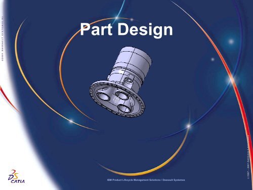
<strong>Part</strong> <strong>Design</strong><br />
IBM Product Lifecycle Management Solutions / Dassault Systemes<br />
Page 1<br />
© 1997 – 2001 DASSAULT SYSTEMES
Tutorial Objectives<br />
Description<br />
? This tutorial is an introduction to <strong>Part</strong> <strong>Design</strong>.<br />
Message<br />
? This tutorial illustrates how <strong>CATIA</strong> can<br />
?<strong>Design</strong> precise 3D mechanical parts with an intuitive and flexible user<br />
interface<br />
?Accommodate design requirements for parts of various complexitiesfrom<br />
simple to advanced<br />
?Apply the combined power of feature-based design with the flexibility<br />
of a Boolean approach<br />
Duration<br />
? 45 minutes<br />
Product Coverage<br />
? <strong>Part</strong> <strong>Design</strong><br />
IBM Product Lifecycle Management Solutions / Dassault Systemes<br />
Page 2<br />
© 1997 – 2001 DASSAULT SYSTEMES
Scenario Major Steps<br />
Here are the major steps of the scenario:<br />
Step 1<br />
? Add a new <strong>Part</strong> body<br />
Step 2<br />
?Create a Shaft feature<br />
Step 3<br />
? Create a Tap<br />
Step 4<br />
? Create a Circular Pattern<br />
Step 5<br />
? Create a Union Trim<br />
Step 6<br />
? Create an Edge Fillet feature<br />
Step 7<br />
? Create a Pad feature<br />
Step 8<br />
? Create a Hole feature<br />
Step 9<br />
? Thread / Tap Analysis<br />
IBM Product Lifecycle Management Solutions / Dassault Systemes<br />
Page 3<br />
© 1997 – 2001 DASSAULT SYSTEMES
Settings 1/2<br />
Depending on your needs, you may have to modify the <strong>CATIA</strong> <strong>V5</strong> settings (units, default<br />
directory, visualisation parameters, etc…)<br />
In order to use the appropriate settings for this tutorial, you have two possibilities:<br />
1. Do the following operations (simplest one):<br />
?BEFORE STARTING YOUR <strong>CATIA</strong> <strong>V5</strong> SESSION:<br />
? Copy or replace the directory ..\<strong>Part</strong> <strong>Design</strong>\Data\CATSettings in:<br />
For NT users<br />
For Windows 2000<br />
or XP users<br />
For Windows<br />
98 users<br />
C:\Winnt\Profiles\XXXXX\Application Data\DassaultSystemes<br />
C:\Documents and settings\Profiles\XXXXX\Application Data\DassaultSystemes<br />
C:\Windows\Profiles\XXXXX\Application Data\DassaultSystemes<br />
XXXX is the name used to log on to your computer<br />
? Do not forget to put this folder (CATSettings) in read mode:<br />
? Select the folder (CATSettings)<br />
? Click mouse button 3 then click on Properties and<br />
uncheck the Read-only Attribute<br />
? Select all the files in the folder<br />
? Click mouse button 3 then click on Properties and uncheck the Read-only<br />
Attribute<br />
2. Set them manually:<br />
? Launch your <strong>CATIA</strong> <strong>V5</strong> session and do the operations from page 40 onwards<br />
IBM Product Lifecycle Management Solutions / Dassault Systemes<br />
Page 4<br />
© 1997 – 2001 DASSAULT SYSTEMES
Settings 2/2<br />
For this tutorial you also need to install a material catalogue:<br />
? Do not do this step if you have already done it in getting started or in a previous tutorial<br />
? Copy the ..\Getting Started\Catalog.CATMaterial file under ..\Program<br />
Files\Dassault Systemes\M07\intel_a\startup\materials\French directory<br />
? Copy the ..\Getting Started\Catalog.CATMaterial file under ..\Program<br />
Files\Dassault Systemes\M07\intel_a\startup\materials\German directory<br />
? Copy the ..\Getting Started\Catalog.CATMaterial file under ..\Program<br />
Files\Dassault Systemes\M07\intel_a\startup\materials\Japanese directory<br />
? Copy the ..\Getting Started\Catalog.CATMaterial file under ..\Program<br />
Files\Dassault Systemes\M07\intel_a\startup\materials directory<br />
? Answer Yes in order to replace the old catalogue<br />
You are now ready to launch your <strong>CATIA</strong> <strong>V5</strong> session<br />
IBM Product Lifecycle Management Solutions / Dassault Systemes<br />
Page 5<br />
© 1997 – 2001 DASSAULT SYSTEMES
Step 1: Read the CAT<strong>Part</strong><br />
? You are going to read a <strong>CATIA</strong> <strong>V5</strong> document<br />
?Click file on the menu bar<br />
?Select open<br />
?The file selection definition box should appear<br />
?Select Spindle_start.CAT<strong>Part</strong> in the<br />
…\<strong>Part</strong> <strong>Design</strong>\Data\ directory where you<br />
installed the scenarios data<br />
?Click Open to confirm the selection<br />
?Answer Yes to the question because some<br />
libraries are not installed in this demonstration<br />
mode<br />
?Maximise the window<br />
IBM Product Lifecycle Management Solutions / Dassault Systemes<br />
Page 6<br />
© 1997 – 2001 DASSAULT SYSTEMES
Step 1: Add a new <strong>Part</strong> Body<br />
? You are going to add a new <strong>Part</strong> Body to allow<br />
Boolean operations<br />
?Reduce the Spindle Body tree by clicking on<br />
the (+) sign<br />
?Right click on Spindle Body<br />
?Select Define In Work Object<br />
?The Spindle Body should now be underlined in the<br />
specification tree to indicate that it is the “In Work<br />
Object”<br />
?Click on Insert on the menu bar<br />
?Select Body<br />
?Body.2 appears in the specification tree and is now<br />
the “in work” body<br />
IBM Product Lifecycle Management Solutions / Dassault Systemes<br />
Page 7<br />
© 1997 – 2001 DASSAULT SYSTEMES
Step 1: Rename the new <strong>Part</strong> Body<br />
? You will learn how to rename a <strong>Part</strong><br />
Body<br />
?Right click on Body.2 to display the<br />
contextual menu<br />
?Select Properties<br />
?The Properties dialog box will appear<br />
?Select Feature Properties tab<br />
? Change the name from Body.2 to<br />
Turret Body<br />
?Click OK to confirm the change<br />
?Turret Body will now be visible in the<br />
specification tree<br />
?You can compress the tree by<br />
clicking on the minus symbol if you’ve<br />
not already done so<br />
IBM Product Lifecycle Management Solutions / Dassault Systemes<br />
Page 8<br />
© 1997 – 2001 DASSAULT SYSTEMES
Step 2: Create a Shaft feature<br />
START POINT<br />
? You are going to draw a sketch and use it to create a<br />
Shaft<br />
? Click on yz plane in the specification tree<br />
? Click on the sketcher icon<br />
? Deactivate the Snap to Point capability by<br />
clicking on the icon (it must not be red)<br />
1<br />
? Click on the profile icon to create the white profile<br />
as shown on the right<br />
? Single-click at the indicated START point and<br />
move cursor down creating a vertical line (1)<br />
? The sketcher assistant tells you when the line is<br />
vertical with the blue colour line<br />
START POINT<br />
END<br />
POINT<br />
? Single click to stop your first line (2)<br />
? Move the cursor left to continue your profile with a<br />
horizontal line<br />
? The sketcher assistant tells you when the line is<br />
horizontal with the blue colour line<br />
? Single click to stop your second line (3)<br />
If you fail to create the sketch go to page 14<br />
3<br />
IBM Product Lifecycle Management Solutions / Dassault Systemes<br />
2<br />
Page 9<br />
© 1997 – 2001 DASSAULT SYSTEMES
Step 2: Create a Shaft feature<br />
START<br />
POINT<br />
END<br />
POINT<br />
?Move the cursor down to continue your<br />
profile with a vertical line<br />
? The sketcher assistant tells you when the line<br />
is vertical with the blue colour line<br />
?Single click to stop your third line (4)<br />
?Move the cursor right to continue your profile<br />
with a horizontal line<br />
? The sketcher assistant tells you when the line<br />
is horizontal with the blue colour line<br />
?Single click to stop your fourth line (5)<br />
6<br />
4<br />
5<br />
7<br />
?Move the cursor down to continue your<br />
profile with a vertical line<br />
? The sketcher assistant tells you when the line<br />
is vertical with the blue colour line<br />
?Single click to stop your fifth line (6)<br />
?Continue the profile until the END point<br />
checking the horizontal and vertical constraints<br />
(blue lines)<br />
IBM Product Lifecycle Management Solutions / Dassault Systemes<br />
Page 10<br />
© 1997 – 2001 DASSAULT SYSTEMES
Step 2: Create a Shaft feature<br />
END<br />
POINT<br />
?Single click at the “END POINT” to<br />
finish the profile and click on the<br />
Profile icon again to exit the function<br />
? Be sure that all geometrical<br />
constraints shown on the right are<br />
visible on the profile<br />
? If one or more geometrical<br />
constraints are missing, follow the<br />
following steps to add the constraint(s)<br />
?Select the line<br />
?Click on Constraints Defined in a<br />
Dialog Box icon<br />
?In the Constraint Definition<br />
window, click on Vertical or<br />
Horizontal box option<br />
?Click OK to confirm selection<br />
? Repeat the same procedure for<br />
any other missing geometrical<br />
constraint(s)<br />
IBM Product Lifecycle Management Solutions / Dassault Systemes<br />
Page 11<br />
© 1997 – 2001 DASSAULT SYSTEMES
Step 2: Create a Shaft feature<br />
?Click on the Corner icon<br />
?Select the two indicated lines<br />
? An arc and and its radius are displayed<br />
?Take care to have the pre-visualisation arc at the<br />
correct location (as shown) before pressing “Enter”<br />
?Enter “38” and the value will be<br />
automatically placed in the Radius field - then<br />
press “Enter”<br />
?Click on the Corner icon<br />
?Select the two indicated lines<br />
? An arc and and its radius are displayed<br />
?Enter 152 and the value will be<br />
automatically placed in the Radius field - then<br />
press “Enter”<br />
?Take care to have the pre-visualisation arc on the<br />
right location (as shown) before pressing “Enter”<br />
? You should have this result<br />
IBM Product Lifecycle Management Solutions / Dassault Systemes<br />
Page 12<br />
© 1997 – 2001 DASSAULT SYSTEMES
Step 2: Create a Shaft feature<br />
1<br />
Axis START<br />
POINT 2<br />
? Create an axis<br />
? Click on the axis icon to add an axis as<br />
shown on the right<br />
?Click in the “1” area. Make sure the line is<br />
blue<br />
?Click in the “2” area<br />
? Add a coincidence constraint between the axis<br />
and START and END points of the sketched axis<br />
line<br />
? Click on the axis<br />
?Press key to multi-select<br />
elements<br />
? Click on the START point<br />
? Click on Constraints Defined in a<br />
Dialog Box icon<br />
?The constraint definition box should<br />
appear<br />
? Check Coincidence box<br />
? Click OK to confirm selection<br />
? Repeat the same procedure for the axis and<br />
the END point of the sketched axis line<br />
IBM Product Lifecycle Management Solutions / Dassault Systemes<br />
COINCIDENCE<br />
CONSTRAINTS<br />
Page 13<br />
© 1997 – 2001 DASSAULT SYSTEMES
Step 2: Create a Shaft feature<br />
? You will add other dimensional<br />
constraints to the sketched profile as<br />
shown on the right<br />
?Click on the Constraint icon<br />
?Select the two indicated lines<br />
?Click on the area where you want<br />
to place the dimension<br />
?Double click on this dimension to<br />
edit it<br />
?Enter “110” in the Value field and<br />
press key<br />
?Repeat these operations to create<br />
the result as shown in the picture<br />
? Remember: to keep an icon active,<br />
you can double-click on it instead of<br />
clicking…<br />
? To create the “75” dimension you<br />
need to select an edge from the 3D<br />
geometry<br />
IBM Product Lifecycle Management Solutions / Dassault Systemes<br />
Page 14<br />
© 1997 – 2001 DASSAULT SYSTEMES
Step 2: Create a Shaft feature<br />
? Modify dimensional constraints to match<br />
the illustration as shown on the right<br />
?Repeat these operations to create<br />
the result as shown in the picture<br />
? When you create the “47”<br />
dimension select the vertical line. Click<br />
on MB3 and select the Position<br />
Dimension option to place the<br />
dimension – this will prevent you from<br />
accidentally selecting the geometry<br />
and creating a wrong dimension.<br />
? If you accidentally create a wrong<br />
dimension, you can restart by clicking<br />
on the Select icon<br />
?Click the Exit Workbench icon<br />
IBM Product Lifecycle Management Solutions / Dassault Systemes<br />
Page 15<br />
© 1997 – 2001 DASSAULT SYSTEMES
Step 2: Create a Shaft feature<br />
? If you fail to create the sketch:<br />
?If you have not already exited the<br />
Sketcher, click on the Exit<br />
workbench icon<br />
?Delete the Sketch.20 you just have<br />
created with MB3 on Sketch.20 +<br />
Delete<br />
?Expand the Open_Body.1 by<br />
clicking on the “+” symbol<br />
?With MB3 on Sketch.20 select<br />
Hide/Show<br />
? If you have succeeded in creating the<br />
sketch, continue with the scenario on the<br />
next page<br />
IBM Product Lifecycle Management Solutions / Dassault Systemes<br />
Page 16<br />
© 1997 – 2001 DASSAULT SYSTEMES
Step 2: Create a shaft feature<br />
? You can now create the shaft feature<br />
?Click on the shaft icon<br />
?The shaft definition box should<br />
appear<br />
? Be sure the parameters in the<br />
definition box match the parameters<br />
shown on the right. Select the sketch<br />
you have just designed if necessary.<br />
?Click on Preview to preview shaft<br />
feature<br />
?Click OK to confirm shaft feature<br />
?The shaft feature is added to the<br />
specification tree<br />
IBM Product Lifecycle Management Solutions / Dassault Systemes<br />
Page 17<br />
© 1997 – 2001 DASSAULT SYSTEMES
Step 3: Create a Tap<br />
? We will add a tap at the end of the shaft<br />
?Click on the thread / tap icon<br />
?The thread / tap definition box should<br />
appear<br />
?Click on the cylinder surface<br />
?Click on the limit face<br />
? Be sure the parameters in the<br />
definition box match the parameters<br />
shown on the right. Select the sketch<br />
you have just designed if necessary.<br />
?Click on Preview<br />
? The result is highlighted<br />
?Click OK to confirm<br />
IBM Product Lifecycle Management Solutions / Dassault Systemes<br />
Page 18<br />
© 1997 – 2001 DASSAULT SYSTEMES
Step 4: Create a circular pattern<br />
? You can create a multi instantiation of the shaft<br />
and of the tap using the circular pattern icon<br />
? Holding the < Crtl > key, Click on Shat.2 and<br />
Thread.1 in the tree.<br />
? Click and keep MB1 on the black arrow at the<br />
bottom right of the Rectangular Pattern icon<br />
? Drag the mouse then release MB1 on the circular<br />
pattern icon<br />
?If you don’t see the icon, it means that the<br />
corresponding toolbar is hidden due to your display<br />
settings. To find it, drag and drop the empty area from the<br />
bottom right side to the centre of the 3D view. Repeat this<br />
operation until you find the right toolbar. To put it back, do<br />
the reverse operation<br />
?The circular pattern definition box should appear<br />
? Select Complete crown in the Parameters field<br />
? Enter 3 for the Instance(s) field<br />
? If not already done so.<br />
? Click on the Reference element field<br />
? Select the external cylinder in the 3D view<br />
? Click OK to confirm circular pattern of shaft<br />
IBM Product Lifecycle Management Solutions / Dassault Systemes<br />
Page 19<br />
© 1997 – 2001 DASSAULT SYSTEMES
Step 5: Create a union trim<br />
? You can use a Boolean operation to<br />
assemble and trim the two bodies<br />
?Right click on Turret Body in the<br />
specification tree<br />
?Select Turret Body object<br />
?Select Union Trim…<br />
?The trim definition box should appear<br />
IBM Product Lifecycle Management Solutions / Dassault Systemes<br />
Page 20<br />
© 1997 – 2001 DASSAULT SYSTEMES
Step 5: Create a union trim<br />
?Click on the Faces to remove field<br />
?Using the mouse, select the 3<br />
faces of the shaft on the geometry as<br />
shown on the right<br />
? The faces should turn pink<br />
?Click on the Faces to keep field<br />
?Using the mouse, select the lower<br />
band of the Spindle Body as shown<br />
on the right<br />
? The face should turn blue<br />
FACES TO REMOVE<br />
IBM Product Lifecycle Management Solutions / Dassault Systemes<br />
FACES TO KEEP<br />
Page 21<br />
© 1997 – 2001 DASSAULT SYSTEMES
Step 5: Create a union trim<br />
?Click Preview to preview union trim<br />
?Click OK to confirm union trim<br />
?Trim.1 is added to the specification<br />
tree<br />
IBM Product Lifecycle Management Solutions / Dassault Systemes<br />
Page 22<br />
© 1997 – 2001 DASSAULT SYSTEMES
Step 6: Create an edge fillet<br />
? You can now create an edge fillet<br />
?Click on the edge fillet icon<br />
? Key in 38mm for the radius field<br />
?Click on Object(s) to fillet field<br />
?Using the mouse,select the 3 inner<br />
edges of the shaft as shown below<br />
?Click OK to confirm edge fillet<br />
feature<br />
EDGE 1<br />
EDGE 3<br />
EDGE 2<br />
IBM Product Lifecycle Management Solutions / Dassault Systemes<br />
Page 23<br />
© 1997 – 2001 DASSAULT SYSTEMES
Step 7: Create a pad feature<br />
? You will create a pad feature, using the<br />
profile sketched on the surface, as shown<br />
on the right<br />
?Click on one of the 3 sketch<br />
surface as shown<br />
?Click on the Sketcher icon<br />
SKETCH SURFACE<br />
IBM Product Lifecycle Management Solutions / Dassault Systemes<br />
Page 24<br />
© 1997 – 2001 DASSAULT SYSTEMES
Step 7: Create a pad feature<br />
? Sketching the pad profile<br />
? Click on the project 3D elements icon<br />
? Select the edge you want to project, as<br />
shown on the right<br />
? Click anywhere off the geometry to<br />
confirm selection of edge<br />
?The colour of the edge should now be<br />
yellow<br />
? Click and hold MB1 on the black arrow at<br />
the bottom right of the Circle icon<br />
? Drag the mouse then release MB1 on the<br />
Arc icon<br />
EDGE TO PROJECT<br />
? Select the origin as the centre point of<br />
the arc<br />
?Make sure the Double circle appears.<br />
This means there will be a coincidence<br />
constraint between this point and the origin<br />
IBM Product Lifecycle Management Solutions / Dassault Systemes<br />
ARC CENTER<br />
POINT<br />
Page 25<br />
© 1997 – 2001 DASSAULT SYSTEMES
Step 7: Create a pad feature<br />
?Click on the start point and end point area<br />
of the arc as shown on the right<br />
START POINT<br />
END POINT<br />
? Connecting the start point of the arc with the<br />
endpoint of the projected edge as shown on the<br />
right<br />
?Click on the line icon<br />
?Select the start point of the arc<br />
?Here again, make sure a Double circle appears<br />
?Select the endpoint of the projected edge<br />
?Here again, make sure a Double circle appears<br />
?Click anywhere off the geometry to confirm<br />
creation of the line<br />
PROJECTED EDGE<br />
ENDPOINT<br />
IBM Product Lifecycle Management Solutions / Dassault Systemes<br />
Page 26<br />
© 1997 – 2001 DASSAULT SYSTEMES
Step 7: Create a pad feature<br />
? You will now duplicate an element using<br />
symmetry<br />
?Click on the Symmetry icon<br />
?Click on the line between the start<br />
point of the arc and the endpoint of<br />
the projected edge.<br />
LINE TO SYMMETRY<br />
SYMMETRICAL<br />
LINE<br />
?Click on the vertical axis. This is<br />
the line from which the element will<br />
remain equidistant<br />
?A line should appear between the<br />
endpoint of the arc and the endpoint of<br />
the projected edge as shown on the<br />
right<br />
?The symmetry symbol should appear<br />
as shown on the right<br />
VERTICAL AXIS<br />
IBM Product Lifecycle Management Solutions / Dassault Systemes<br />
Page 27<br />
© 1997 – 2001 DASSAULT SYSTEMES
Step 7: Create a pad feature<br />
? Adding a coincidence constraint<br />
between the endpoint of the arc and the<br />
endpoint of the symmetrical line as shown<br />
on the right. This will close the contour<br />
? One of the scenarios on the right<br />
should match what you have on your<br />
screen<br />
?Click on the endpoint of the arc<br />
?Hold control key to multi-select<br />
?Click on endpoint of the projected<br />
edge<br />
?Click on Constraints Defined in a<br />
Dialog Box icon<br />
?Check Coincidence box<br />
?Click OK to confirm selection<br />
? Of course, you could have created<br />
the second line with the same<br />
operations used for the first one: the<br />
above operation was just to<br />
demonstrate another functionality<br />
?Click on the Exit Workbench icon<br />
IBM Product Lifecycle Management Solutions / Dassault Systemes<br />
ARC ENDPOINT<br />
SYMMETRICAL<br />
LINE ENDPOINT<br />
Page 28<br />
© 1997 – 2001 DASSAULT SYSTEMES
Step 7: Create a pad feature<br />
?Click on Pad icon<br />
?The pad definition box should appear<br />
?Select the profile you have just<br />
created if needed<br />
?Click on the Reverse Direction<br />
button<br />
?Click on the Type field<br />
?Select Up to plane<br />
?Click on the Limit field<br />
LIMIT (Plane.1)<br />
?Using the mouse select Plane.1 in<br />
the 3D window as shown on the right<br />
IBM Product Lifecycle Management Solutions / Dassault Systemes<br />
Page 29<br />
© 1997 – 2001 DASSAULT SYSTEMES
Step 7: Create a pad feature<br />
?Click OK to confirm pad feature<br />
?Select View / Tree Expansion /<br />
Expand First Level<br />
IBM Product Lifecycle Management Solutions / Dassault Systemes<br />
Page 30<br />
© 1997 – 2001 DASSAULT SYSTEMES
Step 7: Create a circular pattern<br />
? Creating a multi instantiation of the pad<br />
using the circular pattern icon<br />
?Click on Pad.3 in the specification<br />
tree<br />
?Click on the Circular Pattern icon<br />
?The circular pattern definition box<br />
should appear<br />
?Select Complete crown in the<br />
Parameters field<br />
?Enter 3 in the Instance(s) field<br />
?Click on the Reference element<br />
field<br />
?Click on the external cylinder in the<br />
3D view<br />
?Click on Preview to preview<br />
circular pattern of pad<br />
?Click OK to confirm circular pattern<br />
of pad<br />
IBM Product Lifecycle Management Solutions / Dassault Systemes<br />
Page 31<br />
© 1997 – 2001 DASSAULT SYSTEMES
Step 8: Create a hole feature<br />
? You will use the drag and drop feature<br />
of <strong>V5</strong> to create a hole feature<br />
AREA FOR HOLE<br />
?Drag and drop the Hole icon<br />
?Make sure you keep MB1 pressed<br />
when using drag and drop feature<br />
?Release the icon on the surface<br />
where you want to create the hole, as<br />
shown on the right<br />
IBM Product Lifecycle Management Solutions / Dassault Systemes<br />
Page 32<br />
© 1997 – 2001 DASSAULT SYSTEMES
Step 8: Create a hole feature<br />
? Changing the extension type of the hole<br />
from Blind to Up To Plane<br />
?Click on pull down arrow and<br />
change setting from Blind to Up To<br />
Plane<br />
?Click on the Diameter field<br />
? Key in 120 mm<br />
?Click on Limit field<br />
?Select Plane.1 in the 3D window as<br />
shown on the right<br />
IBM Product Lifecycle Management Solutions / Dassault Systemes<br />
LIMIT (Plane.1)<br />
Page 33<br />
© 1997 – 2001 DASSAULT SYSTEMES
Step 8: Create a hole feature<br />
? You will now add a concentricity<br />
constraint between the hole and the inner<br />
hole of the shaft<br />
?Click on the Sketcher icon in the<br />
Hole Definition box<br />
? This automatically takes you into<br />
the sketcher workbench<br />
?Click on centre point of the hole as<br />
shown on the right<br />
?Hold control key to multi-select<br />
?Click on inner hole of the shaft as<br />
shown on the right<br />
? Click on Constraints Defined in a<br />
Dialog Box icon<br />
?Check Concentricity box<br />
?Click OK to confirm selection<br />
HOLE CENTRE POINT<br />
IBM Product Lifecycle Management Solutions / Dassault Systemes<br />
SHAFT INNER HOLE<br />
Page 34<br />
© 1997 – 2001 DASSAULT SYSTEMES
Step 8: Create a hole feature<br />
?Click on the Exit icon<br />
?Click on Preview to preview hole<br />
feature<br />
?Click OK to confirm hole feature<br />
IBM Product Lifecycle Management Solutions / Dassault Systemes<br />
Page 35<br />
© 1997 – 2001 DASSAULT SYSTEMES
Step 8: Create a circular pattern<br />
? Creating a circular pattern of the hole<br />
using the circular pattern icon<br />
?Click on the Circular Pattern icon<br />
?Click on Hole.6 in the specification<br />
tree<br />
?The circular pattern definition box<br />
should appear<br />
?Select Complete crown in the<br />
Parameters field<br />
?Enter 3 in the Instance(s) field<br />
?Click on the Reference element<br />
field<br />
?Click on the external cylinder in the<br />
3D view<br />
?Click on Preview to preview<br />
circular pattern of hole<br />
?Click OK to confirm circular pattern<br />
of hole<br />
IBM Product Lifecycle Management Solutions / Dassault Systemes<br />
Page 36<br />
© 1997 – 2001 DASSAULT SYSTEMES
Step 9 : Thread / Tap Analysis<br />
? Check every tap / thread realised in<br />
your part<br />
? Click on the Tap – Thread<br />
Analysis icon<br />
? As previously, if the icon is not<br />
visible, drag and drop the bottom<br />
right toolbars…<br />
? Switch off Show numerical value<br />
? All manufacturing is highlighted.<br />
? Click on Apply to show the threads<br />
and taps.<br />
?Click on Close to finish<br />
IBM Product Lifecycle Management Solutions / Dassault Systemes<br />
Page 37<br />
© 1997 – 2001 DASSAULT SYSTEMES
End of scenario<br />
? You now have the final part as shown<br />
on the right<br />
? CONGRATULATIONS<br />
IBM Product Lifecycle Management Solutions / Dassault Systemes<br />
Page 38<br />
© 1997 – 2001 DASSAULT SYSTEMES
Manual Settings<br />
IBM Product Lifecycle Management Solutions / Dassault Systemes<br />
Page 39<br />
© 1997 – 2001 DASSAULT SYSTEMES
Settings<br />
Tools/Options<br />
? We will configure the environment of<br />
<strong>CATIA</strong><br />
?Select Tools + Options menu<br />
? We will erase any previous<br />
configurations.<br />
?Click on General<br />
?Click on the Reset Bottom<br />
?Select for all the tabpages<br />
?Click YES<br />
IBM Product Lifecycle Management Solutions / Dassault Systemes<br />
Page 40<br />
© 1997 – 2001 DASSAULT SYSTEMES
Settings<br />
Tools/Options<br />
? Under General select Display on the<br />
tree<br />
?Check Fixed Size and enter 20 as<br />
value in the field.<br />
IBM Product Lifecycle Management Solutions / Dassault Systemes<br />
Page 41<br />
© 1997 – 2001 DASSAULT SYSTEMES
Congratulations<br />
IBM Product Lifecycle Management Solutions / Dassault Systemes<br />
Page 42<br />
© 1997 – 2001 DASSAULT SYSTEMES