1998 S/N 21329 - Walker Mowers
1998 S/N 21329 - Walker Mowers
1998 S/N 21329 - Walker Mowers

You also want an ePaper? Increase the reach of your titles
YUMPU automatically turns print PDFs into web optimized ePapers that Google loves.
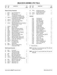
Maintenance Instructions<br />
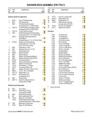
ADJUSTMENTS<br />
Stop Block<br />
Blade Clutch<br />
Idler Pulley<br />
1/8 in.<br />
(3 mm)<br />
2. After adjustments are complete, check blade<br />
brake action as described in CHECKING/SER-<br />
VICING the Blade Brake Action in this section.<br />
If blades do not stop within five (5) seconds,<br />
check the following:<br />
a. Recheck 1/8 in. (3 mm) gap between stop<br />
block and chassis.<br />
b. Make sure clutch and brake linkage are<br />
working freely (no binding).<br />
c. Check the brake band lining.<br />
PTO Belt Tightener<br />
Chassis<br />
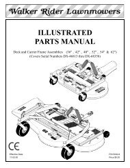
Blade Brake Band Adjustment<br />
NOTE: The length of the actuator rod is adjusted<br />
by disconnecting the bottom clevis and shortening<br />
or lengthening accordingly. The standard pre-set<br />
length of the actuator rod is set at the factory at<br />
8-1/4 in. (209 mm).<br />
d. Check the brake drum on the pulley. If<br />
excessive wear is present, it will be necessary<br />
to replace worn parts.<br />
Transmission Control<br />
IMPORTANT: The proper adjustment of the transmission<br />
control stops is essential for efficient operation<br />
and life of the transmission. These stops are<br />
properly adjusted at the factory and should only require<br />
readjustment if the transmission or related<br />
control linkage is removed or changed.<br />
NOTE: It would not be unusual for a new machine,<br />
after initial 5 or 10 hours of operation, to begin to not<br />
travel straight (this is due to the break-in of the<br />
transmissions). In this case, proceed to Straight<br />
Ground Travel Adjustment - Step 4.<br />
8-1/4 in.<br />
(209 mm)<br />
Locknuts<br />
Bottom<br />
Clevis<br />
IMPORTANT: The following adjustment procedures<br />
are sequential. Check and adjust each function<br />
in the order given.<br />
Set Forward Travel Limit (Stop) - Step 1<br />
1. Move the Forward Speed Control (FSC) lever to<br />
the most FORWARD position.<br />
2. Check clearance of the RH and LH steering lever<br />
actuator arms with the frame and adjust forward<br />
stop bolt so each lever clears the frame<br />
by at least 1/16 in. (1.6 mm). Clearance of the<br />
arm to the frame should be checked while applying<br />
pressure back on the arm to remove<br />
any slack in the linkage.<br />
Brake Actuator Rod Adjustment<br />
77