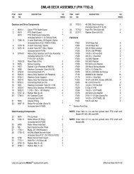
1998 S/N 21329 - Walker Mowers
1998 S/N 21329 - Walker Mowers
1998 S/N 21329 - Walker Mowers

You also want an ePaper? Increase the reach of your titles
YUMPU automatically turns print PDFs into web optimized ePapers that Google loves.
Operating Instructions<br />
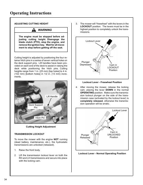
ADJUSTING CUTTING HEIGHT<br />
WARNING<br />
The engine must be stopped before adjusting<br />
cutting height. Disengage the<br />
blade clutch (PTO), stop the engine, and<br />
remove the ignition key. Wait for all movement<br />
to stop before getting off the seat.<br />
3. The mower will “freewheel” with the levers in the<br />
LOCKOUT position. The levers must be in the<br />
highest position to completely unlock the transmissions.<br />
Lockout Lever<br />
Cutting height is adjusted by positioning the four retainer<br />
hitch pins in a series of seven vertical holes on<br />
the deck support pins. Lift handles have been provided<br />
on each end of the deck to assist in raising the<br />
deck while positioning the hitch pins. Cutting<br />
heights range from 1 in. (25 mm) [top holes] to 4 in.<br />
(102 mm) [bottom holes] in 1/2 in. (13 mm) increments.<br />
Plunger<br />
Depressed<br />
Cam in<br />
LOCKOUT<br />
Position<br />
Deck Support<br />
Pin<br />
Lift Handle<br />
Lockout Lever - Freewheel Position<br />
4. After moving the mower, release the locking<br />
cam, placing the lever DOWN in the normal<br />
OPERATING position. Make sure the transmission<br />
lockout plunger on the side of the transmission<br />
case (activated by the lockout lever) is<br />
completely released, otherwise the transmission<br />
operation will be erratic.<br />
Lockout Lever<br />
Hitch Pin<br />
Cutting Height Adjustment<br />
TRANSMISSION LOCKOUT<br />
To move the mower with the engine NOT running<br />
(dead battery, maintenance, etc.), the hydrostatic<br />
transmissions are unlocked (released).<br />
Plunger<br />
Released<br />
Cam in<br />
UNLOCKED<br />
Position<br />
1. Raise the front body.<br />
2. Lift the transmission lockout lever on both the<br />
RH and LH transmissions and secure into place<br />
with the locking cam.<br />
Lockout Lever - Normal Operating Position<br />
34