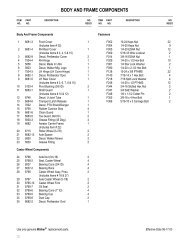
1998 S/N 21329 - Walker Mowers
1998 S/N 21329 - Walker Mowers
1998 S/N 21329 - Walker Mowers

You also want an ePaper? Increase the reach of your titles
YUMPU automatically turns print PDFs into web optimized ePapers that Google loves.
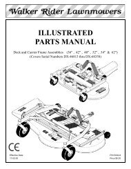
Assembly Instructions<br />
Grease Fitting<br />
Locations<br />
Spacer Washer<br />
Axle Spacer Tube<br />
Deck Caster Wheel Installation<br />
NOTE: If semi-pneumatic wheels are installed,<br />
make sure the spacer washers fit over the spacer<br />
tube and are not caught between the fork and the<br />
end of the tube. The washers should move freely<br />
on the axle spacer tube.<br />
Deck Discharge Shield Installation<br />
(Side Discharge Models Only)<br />
Attach the deck side discharge shield by positioning<br />
the shield hinge lug in front of the deck mount and<br />
fastening with two 3/8-16 x 1-1/4 in. bolts, 3/8-16<br />
ESNA nuts, and 3/8 in. wave spring washers. The<br />
wave washers fit between the two hinging surfaces.<br />
Tighten the nuts until the shield moves freely but is<br />
not loose.<br />
WARNING<br />
DO NOT operate the machine without the<br />
grass deflector chute attached and in the<br />
lowest possible position.<br />
Attach Shield<br />
5. Grease the caster wheel bearings and caster<br />
pivot bearings - one grease fitting for each wheel<br />
and each pivot.<br />
Deck Discharge Chute Installation<br />
(GHS Rear Discharge Models Only)<br />
Mount the discharge chute hinge on top of the deck<br />
discharge opening using the 1/4-20 x 1/2 in. socket<br />
button head bolt and 1/4-20 ESNA nut. Position the<br />
bolt with the head inside of the chute and the nut on<br />
the outside.<br />
Discharge Shield Installation<br />
on Side Discharge Deck<br />
PTO Shaft Guard Installation<br />
Carrier Frame<br />
Tube Sockets<br />
Attach Guard<br />
Attach Chute<br />
Position the shaft guard as shown and mount with<br />
two 1/4-20 x 1/2 in. bolts.<br />
Mower Deck lnstallation on Tractor<br />
Deck Installation<br />
1. Lightly grease each deck support arm (2) on the<br />
tractor. Refer to Mower Deck Installation photo<br />
on next page for location of deck support arm.<br />
Nut on Top<br />
Discharge Chute and PTO Shaft Guard<br />
Installation on Rear Discharge Deck<br />
2. Engage the deck carrier frame tube sockets on<br />
the tractor support arms (refer to Discharge<br />
Chute and PTO Shaft Guard Installation<br />
photo for socket location). Slide the deck onto<br />
the support arms: all the way if SD equipped<br />
model, approximately 3 in. (76 mm) if GHS<br />
equipped model.<br />
18